Article

A Hierarchical Inverse Lithography Method Considering the Optimization and Manufacturability Limit by Gradient Descent

1
National Key Laboratory of Optical Field Manipulation Science and Technology, Chinese Academy of Sciences, Chengdu 610209, China
2
State Key Lab of Optical Technologies on Nano-Fabrication and Micro-Engineering, Chinese Academy of Sciences, Chengdu 610209, China
3
Institute of Optics and Electronics, Chinese Academy of Sciences, Chengdu 610209, China
4
University of Chinese Academy of Sciences, Beijing 100049, China
*
Author to whom correspondence should be addressed.
Micromachines 2025, 16(7), 798; https://doi.org/10.3390/mi16070798
Submission received: 8 June 2025 / Revised: 24 June 2025 / Accepted: 25 June 2025 / Published: 8 July 2025
(This article belongs to the Section E:Engineering and Technology)

Abstract

Inverse lithography technology (ILT) based on the gradient descent (GD) algorithm, which is a classical local optimal method, can effectively improve the lithographic imaging fidelity. However, due to the low-pass filtering effect of the lithography imaging system, GD, although able to converge quickly, is prone to fall into the local optimum for the information in the corner region of complex patterns. Considering the high-frequency information of the corner region during the optimization process, this paper proposes a resolution layering method to improve the efficiency of GD-based ILT algorithms. A corner-rounding-inspired target retargeting strategy is used to compensate for the over-optimization defect of GD for inversely optimizing the complex pattern layout. Furthermore, for ensuring the manufacturability of masks, differentiable top-hat and bottom-hat operations are employed to improve the optimization efficiency of the proposed method. To confirm the superiority of the proposed method, multiple optimization methods of ILT were compared. Numerical experiments show that the proposed method has higher optimization efficiency and effectively avoids the over-optimization.

1. Introduction

Lithography is a cornerstone of modern fabrication, extending far beyond integrated circuit (IC) manufacturing to critical applications in photonics and optoelectronics [1,2,3,4,5]. This versatile technique plays a pivotal role in the development of devices across various cutting-edge fields, including optical communication systems, metasurfaces, metalenses for light manipulation, optical micro-electromechanical systems (MEMSs) for sensing and actuation, and quantum photonics for quantum information processing. These applications rely on the precision of lithographic patterning to achieve the required miniaturization, accuracy, and functionality. Beyond ICs, lithography has become indispensable in producing intricate structures that manipulate light on both macroscopic and microscopic scales, driving advancements in technologies such as high-speed communication, imaging, and quantum computing. As a mainstream method of lithography, projection lithography technology employs a high-uniformity illumination system and a high-resolution objective system to implement the transfer of nanoscale pattern on the wafer surface, which is similar to the camera principle [6]. As the critical dimension (CD) of IC pattern continues to shrink, the numerical aperture (NA) of the objective system needs to be enlarged to ensure resolution at a constant illumination wavelength. Due to the objective lens system being a strictly diffraction-limited system, it is prone to the loss of high-frequency diffraction information during the imaging process, resulting in imaging distortion. The above phenomenon, known as the optical proximity effect (OPE) [7], will seriously affect the yield of IC manufacturing in the lithography process. Optical proximity correction (OPC), a resolution enhancement technique (RET), can effectively improve the imaging fidelity of lithography optical system by modifying the edges of feature patterns or adding assist features.
Rule-based OPC, as one of the traditional resolution enhancement techniques (RETs), is employed to eliminate the OPE in the early IC manufacturing process [8]. In this method, the correction rules are formed by calculating the offsets that need to be corrected for feature patterns under different conditions based on aerial image simulation or the actual pattern on the wafer surface. However, this method still has limitations for dealing with complex patterns [9]. In order to achieve higher resolution and imaging fidelity, the model-based OPC approach has been proposed, which centers on building a simulation system based on an optical model and a photoresist model to compute the desired lithographic feature pattern [10,11,12,13]. Nevertheless, due to the adaptability of the local correction scheme and Manhattan geometry correction constraints, the model-based OPC method is still limited under dense layouts [14].
Inverse lithography technology (ILT) with the model-based OPC approach as a starting point, as a core technology to enhance the lithographic imaging fidelity and process window in the advanced node, pixelates the feature pattern and optimizes the feature pattern layout via an optimization algorithm in reverse [15]. Gradient-based optimization algorithms, as a classical local optimization method, such as gradient descent (GD), conjugate gradient (CG), and steepest descent (SD), are widely employed to optimize the feature pattern layout in ILT for improving the lithographic imaging fidelity and limit resolution, which has the advantages of fast convergence and simple structure [16,17,18,19,20,21,22,23,24,25]. Xion et al. derived a gradient-based framework to automatically generate the optimum masks, which can reduce the edge placement errors and provide a good image fidelity [18]. Wei et al. proposed a multi-objective optimization with a defocus sensitivity penalty function as an objective to improve the lithographic process window via the mini-batch GD method [23]. For promoting the focusing performance, their method has been verified to be effective. Yu et al. employed a generic GD approach to optimize the lithographic imaging fidelity with two objective functions that are the resist and aerial image, respectively [17]. They confirmed that the combination of two objective functions in ILT based on GD can achieve a good feature pattern correction. These research results have confirmed that the gradient-based algorithm with multiple optimization strategies can match well with the lithographic imaging model and improve the imaging fidelity and process window. However, most of the objective functions in the above methods, such as aerial image error, resist image error, and edge placement errors (EPEs), were only considered to optimize a large range of errors between the actual simulation and the desired value for aerial images or resist patterns. The loss of high-frequency information, such as edges and corners of feature patterns, which is introduced by diffraction-limited factors, still cannot be rigorously addressed.
For optimizing the imaging fidelity utilizing ILT, in addition to the gradient-based optimization methods, researchers have employed other algorithms such as deep learning, machine learning, and heuristic algorithms with effective results. However, most of these methods are still focused around reducing the pattern errors and improving the match with lithographic imaging models. Considering that the gradient-based optimization method is prone to fall into a local optimum in the optimization of complex feature patterns, this paper aims to improve the optimization efficiency of GD-based ILT, reduce feature pattern manufacturability, and address the optimization of edges and corners information for aerial images. In this paper, a GD-based hierarchical inverse lithography method is proposed to resolve the above issues. For solving the over-optimization during the computation of ILT, a corner-rounding-inspired target retargeting strategy is employed to improve the optimized directionality. By incorporating differentiable top-hat and bottom-hat transformations—which detect feature size and spacing violations, respectively—our method explicitly trades off lithographic pattern fidelity against mask manufacturability constraints during gradient-based optimization. The experimental results show that the proposed method, compared with other ILT methods, improves the optimization efficiency by introducing a corner-rounding-inspired target retargeting strategy for optimizing imaging fidelity and manufacturability, which provides a superior solution for complex feature pattern optimization in advance nodes.

2. Lithography Imaging Model

The imaging process of the lithography system is based on the partially coherent theory, which is derived by the accumulation of a series of aerial images achieved by sub-light sources [9]. The imaging process of a point source is the same as completely coherent imaging, which can be expressed by Equations (1) and (2). In this completely coherent imaging model, it is assumed that a designed mask with the feature pattern can be represented as m R N × N .
U S i x , y ; S i , x , S i , y = H f x + S i , x , f y + S i , y M f x , f y e i 2 π f x + S i , x x + f y + S i , y y d f x d f y
I x , y = S S i , x , S i , y U S i x , y ; S i , x , S i , y 2 d S i , x d S i , y
where U S i x , y ; S i , x , S i , y explains that the amplitude distribution of image generated by the i t h sub-light source S i with coordinates S i , x , S i , y in the source of the partially coherent imaging model. f x , f y and f x , f y both express the spatial frequency coordinates on the pupil plane, M f x , f y represents the spectral information generated by the Fourier Transform of mask m , and H f x , f y denotes the projection pupil. Therefore, the intensity distribution I x , y in the partially coherent imaging model can be expressed by Hopkins’ mode.
I x , y = T C C f x , f y , f x , f y M f x , f y M * f x , f y e i 2 π f x f x x + f y f y y d f x d f y d f x d f y
And
T C C f x , f y , f x , f y = S S i , x , S i , y H f x + S i , x , f y + S i , y H * f x + S i , x , f y + S i , y d S i , x d S i , y
where M * f x , f y and H * f x , f y indicate the complex conjugate of M and H , respectively. The symbol S indicates the partial coherent source in the imaging. T C C f x , f y , f x , f y is the transmission cross-coefficient matrix. In order to reduce the computational complexity, the T C C matrix can be decomposed into a series of low-rank kernels by singular value decomposition. These low-rank kernels are explained as h k R P × P , and each kernel is associated with an eigenvalue γ k . Thus, the transformation from the feature patter of mask to aerial image can be approximated by Hopkins mode as shown in Equation (5).
I x , y k = 1 N γ k h k x , y m x , y 2
The method proposed is designed to solve the discrepancy of pattern layout between reality and ideal on the photoresist by optimizing the feature patterns in this paper. Moreover, the photoresist pattern (PRP) can be calculated by the resist effect approximated as the sigmoid function, which can be expressed as follows:
I P R P x , y = Γ I x , y = 1 1 + exp α r I x , y t r
Here, I P R P represents the intensity distribution of the PRP layout. The operational symbol Γ · is the sigmoid function, which is a regular S-type function. α r is the steepness index, and t r is the threshold value of the photoresist.

3. Methodology

3.1. Inverse Lithography

The objective of ILT is to determine the optimal mask m * such that the resulting resist pattern closely matches the target design I P R P * . However, in practical fabrication processes, variations in process parameters such as defocus and exposure dose can cause deviations in the actual resist pattern [9]. To ensure performance stability under these variations, robustness must also be considered during optimization [17]. Mathematically, ILT can be formulated as an optimization problem in which the cost function L c is minimized to obtain a mask design that ensures high pattern fidelity and robust process performance, incorporating fidelity terms L f [26,27]. In addition, to ensure that the optimization process satisfies specific constraints, penalty terms L r are incorporated into the cost function to enforce design requirements and achieve a balanced trade-off.
m * = a r g   m i n M β f L f + β r L r
where L f represents the fidelity metric and L r denotes the regularization penalty, each weighted by β f and β r . The fidelity metric, quantified as the L2 loss, functions as a quantitative parameter for assessing the congruence between the intended target pattern and the actual resist pattern produced. It is mathematically represented by the squared norm of the element-wise difference between these two patterns [28].
L f = | | I P R P I P R P * | | 2 2
Meanwhile, the regularization term L r introduces essential constraints that ensure the mask design remains manufacturable and adheres to practical fabrication requirements [29,30,31]. By incorporating both the fidelity metric and the regularization term into the optimization objective function, the method achieves a balanced trade-off between accurately reproducing the desired pattern and satisfying design constraints. Since a binary photomask can only represent two transmission levels—0 for opaque regions and 1 for transparent regions—directly optimizing these discrete states results in a challenging combinatorial problem that is computationally intractable [9]. To circumvent this difficulty, the mask design is relaxed into a continuous and differentiable pattern [26]. Specifically, the binary constraints are softened by mapping mask parameters onto a continuous interval between 0 and 1. This relaxation transforms the original discrete optimization into a continuous one, enabling the use of gradient-based optimization techniques and significantly improving computational efficiency [32].
m x , y = Γ m c ( x , y ) = 1 1 + e x p α m m c x , y t m
Here, m refers to the binary mask, m c represents the continuous transmission mask (CTM), whose values are continuous and can vary within the interval [0, 1]. α m and t m govern the sharpness and threshold of the sigmoid function, respectively [33]. Building upon these formulations, the modified fidelity cost function is derived and expressed as follows:
L f = x = 1 N y = 1 N 1 1 + exp α r k = 1 N γ k ϕ k 1 1 + exp α m m c ( x , y ) t m 2 t r R t 2
Drawing from the fidelity cost function above, the corresponding gradient of the CTM can be derived as follows [33,34]:
L f = 2 α r α m m c 1 m c Φ I P R P 1 I P R P I P R P R t m c Φ * + Φ * I P R P 1 I P R P I P R P R t m c Φ
Here, Φ represents the sum of weighted convolution kernels, expressed as Φ = k = 1 K ω k ϕ k , and the circled dot symbol ⊙ denotes element-wise multiplication. The manufacturability metric consists of two components: the binary penalty term and the complexity penalty term [26]. The binary penalty term encourages the optimized mask pixels to be close to either 0 or 1, ensuring the mask adheres to the discrete nature of binary patterns. The complexity penalty term, on the other hand, prevents the mask from forming isolated or disconnected shapes, thereby promoting smooth and manufacturable designs. The gradient of the manufacturability metric can be expressed as L r . Once the gradient is computed, the mask is updated iteratively using the gradient descent algorithm, as shown in the following update rule:
m c k + 1 = m c k η β f L f + β r L r
where m c i denotes the optimized CTM obtained at the i-th iteration, and η represents the learning rate, which governs the step size during each optimization update. The gradient descent process continues iteratively until either the iteration count reaches a predefined maximum number of iterations or the cost function value decreases below a specified tolerance threshold. Once these stopping criteria are met, the optimization process concludes, yielding the resultant optimized CTM. Subsequently, a binarization step is applied to the optimized CTM to generate the corresponding binary mask m f i n a l , which is defined as follows:
m f i n a l = 1 , M c 0.5 0 , M c < 0.5
To enhance the efficiency of gradient-based ILT optimization, a hierarchical approach is employed by first performing optimization at a reduced spatial resolution. This reduction leads to a decrease in the computational burden of the optimization process [35,36]. When the mask downsampling factor is set to s, the downsampled mask is represented as m ( s x , s y ) . Performing the ILT optimization on this lower-resolution mask results in faster convergence, as the optimization is conducted in a lower-dimensional parameter space. After the low-resolution mask is optimized, it is upsampled using interpolation techniques to obtain the high-resolution approximation optimization results. Finally, binarization is performed to generate the optimized binary mask. The schematic diagram of mask downsampling optimization is illustrated in Figure 1 below.

3.2. Corner Rounding

In edge-based OPC, the semiconductor industry typically adjusts the placement of edge placement error (EPE) measurement points to guide the OPC workflow more effectively. Instead of directly positioning these measurement points near polygon corners, which can lead to over-optimization, they are strategically relocated to the interior of convex corners or the exterior of concave corners [37,38]. This adjustment facilitates more efficient alignment of contours with the target during OPC, thereby reducing the risk of over-optimization and expanding the process window.
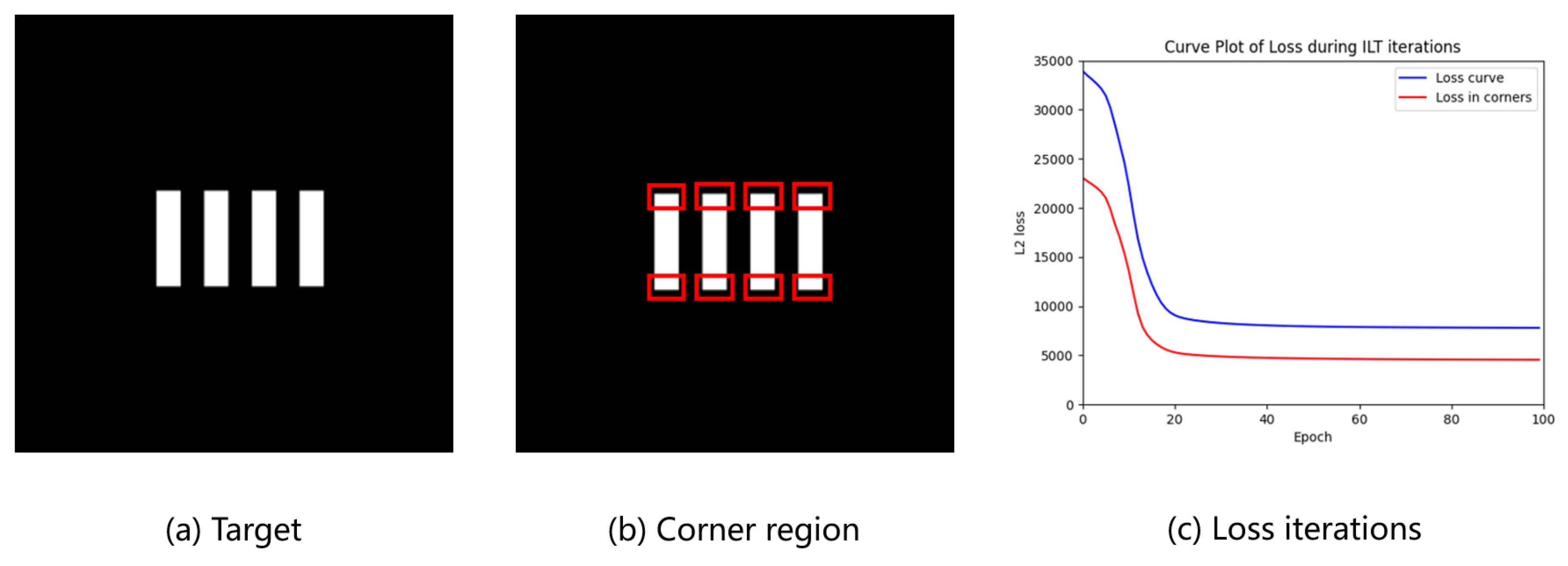
While ILT aims to optimize the entire design pattern rather than sampled control points, discrepancies between the resist and the design can still induce significant gradient variations during optimization. As illustrated in Figure 2, the objective function evolves throughout the optimization process. In the later stages of training, it becomes evident that mismatches at polygon corner regions continue to contribute substantially to the total cost. This persistent contribution often leads to premature convergence, hindering the achievement of further optimization improvements. As a result, the optimizer may disproportionately focus on infeasible targets, leading to suboptimal solutions that adversely affect the overall process robustness. Furthermore, conventional approaches that relocate EPE measurement points to mitigate corner-related challenges are inherently incompatible with pixel-based inverse optimization techniques [28].
The projection lithography system is diffraction-limited. Referring to the theorem of incoherent imaging, the cutoff frequency denoted as f c u t is [35]
f c u t = N A 1 + σ o u t λ 0
where NA denotes the numerical aperture, σ o u t represents the maximum partial coherence factor, and λ 0 corresponds to the illumination wavelength. So that we can estimate the limit of lithography imaging by the following equation [27].
m f i l t e r x , y = m x , y K g a u s s x , y
K g a u s s u , v = 1 2 π σ 2 e u 2 + v 2 2 σ 2 , σ = f c u t
To approximate the ideal imaging characteristics of a lithographic system, the mask pattern is initially filtered using a Gaussian kernel to produce a grayscale mask representation. While this result does not represent the optimal lithographic output, the low-pass filtering properties effectively simulate the imaging behavior under idealized process conditions. In traditional ILT frameworks, the target pattern is inherently binary. To align the filtered grayscale mask with this binary requirement, thresholding is typically applied. However, arbitrary threshold selection can significantly influence the fidelity of the binarized output. This method introduces an edge-driven thresholding strategy: the edges of the original target pattern are first sampled, and the corresponding maximum pixel intensity values in the filtered mask are extracted as the threshold. Edge detection is implemented through morphological erosion operations, mathematically expressed as [39]:
E r o d e m , K i , j = m i n m i k 1 , j k 2 | k 1 , k 2 K
where K is a 3 × 3 structural kernel during erosion. The disappearing region after erosion is the pattern contour.
c o n t o u r = m i , j E r o d e m , K i , j
After selecting a threshold and binarizing, the mask can be retargeted to a corner rounding structure.
T h r e s h o l d = m a x { m f i l t e r e d ( i , j ) c o n t o u r ( i , j ) }
m r e ( x , y ) = 0 m T h r e s h o l d 1 m > T h r e s h o l d
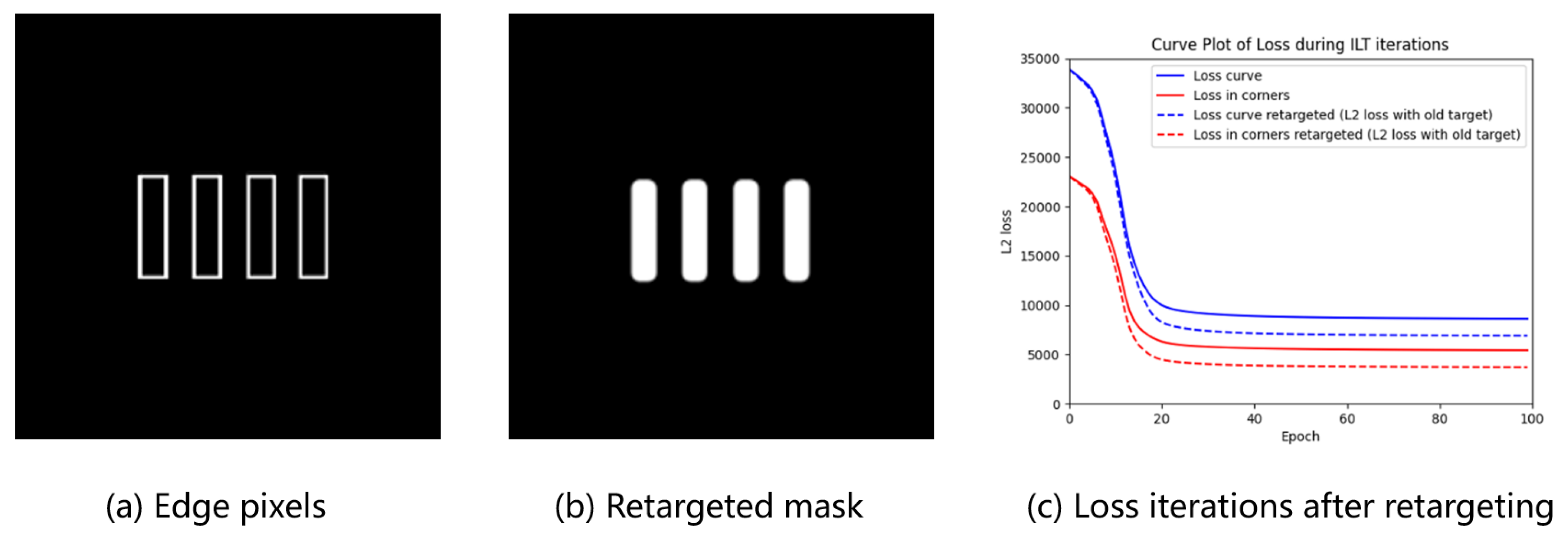
Figure 3 illustrates the re-targeting process in our framework: (a) depicts the extracted boundary elements from the original design, while (b) presents the realigned optimization target after applying our method. Notably, the sharp line ends in the raster structure are visibly smoothed post-realignment, indicating improved compatibility with lithographic resolution limits. The evolution of the cost function during optimization—both globally and specifically for corner regions—demonstrates that the proposed approach converges to a more robust solution. Compared to conventional methods, our strategy allocates reduced emphasis on non-optimizable edge features, thereby mitigating over-optimization associated with sub-wavelength pattern discontinuities.

3.3. MRC and Violation Penalty

The efficacy of ILT hinges not only on its ability to achieve high-fidelity wafer patterns but also on the practical feasibility of the mask itself. This is where mask rule checks (MRCs) become indispensable. MRCs refers to a set of geometric constraints applied to mask designs to ensure their manufacturability. These constraints typically include parameters such as [40,41]:
  • Minimum feature size: The smallest allowable dimension of a pattern element;
  • Minimum spacing: The smallest permitted distance between adjacent features;
  • Minimum feature area: The smallest area allowed for a single feature.
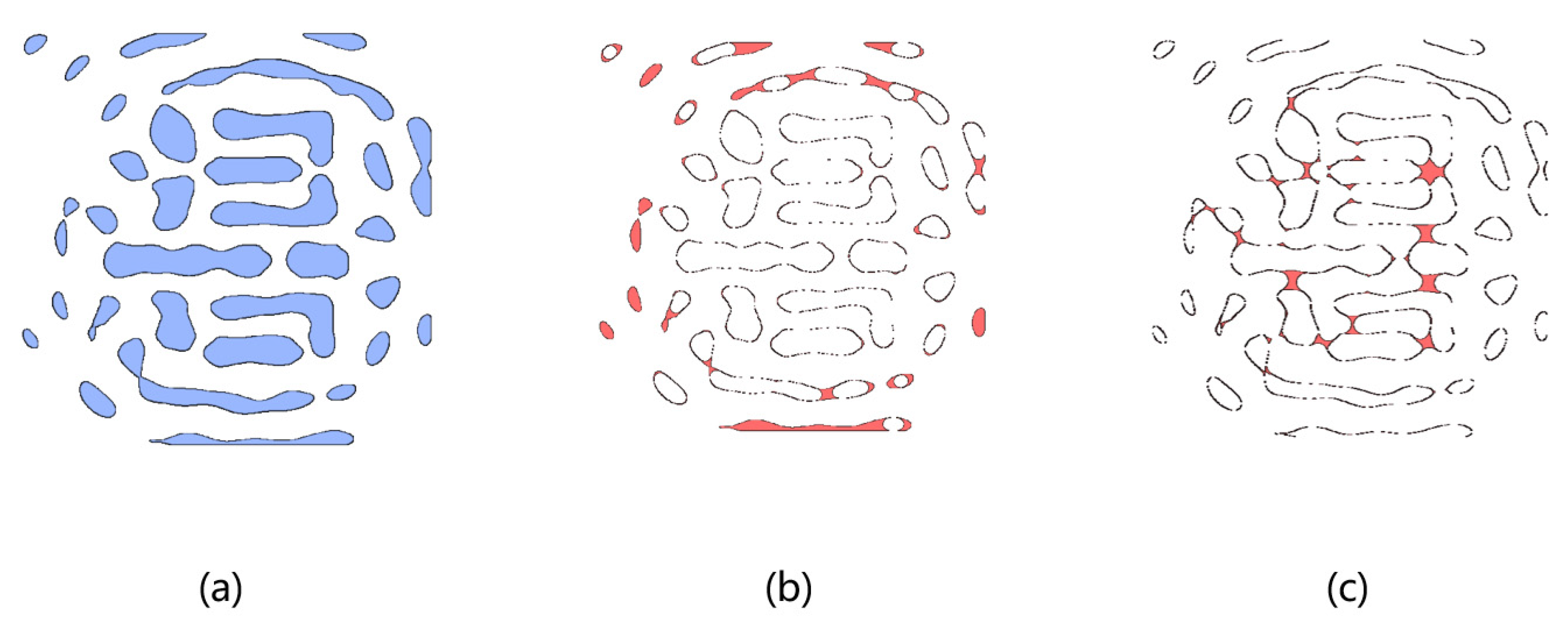
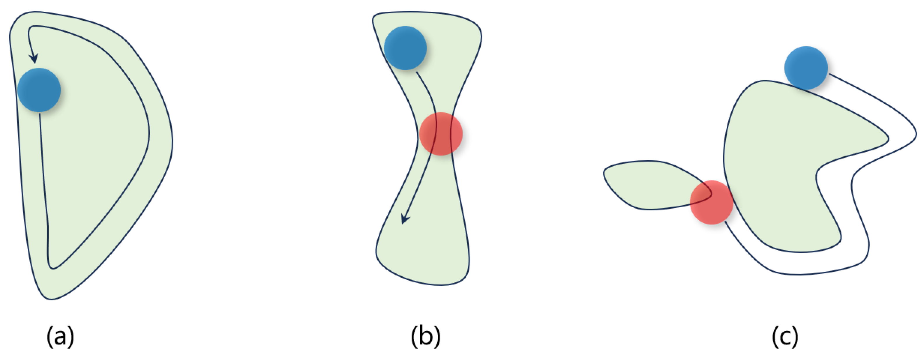
Without considering MRCs, the optimized masks cannot be applied for manufacturability. Compared with Manhattan-shaped masks, the task of MRCs is simpler. The MRC involves two steps. First, a circle of a specific diameter (blue in Figure 4) is rolled along the interior of the mask shape. This ensures the circle remains entirely within the mask structure during movement. Second, a second circle with a potentially different diameter (red in Figure 4) is rolled along the exterior of the shape. This guarantees the circle stays outside the mask region and does not encroach on adjacent features. Both operations require the circles to traverse the contour completely without violating their respective spatial constraints.
Integrating MRCs into the ILT workflow is critical for ensuring manufacturability. Compared to post-optimization MRC correction, a differentiable quantitative metric that evaluates the degree of design rule violations and integrates it into the optimization cost function enables graded penalties for non-compliant patterns. This approach enhances the ability of ILT to generate manufacturable masks while improving pattern fidelity. The morphological operations described above—such as rolling a circle along the interior and exterior contours of a design—can be mathematically represented through morphological processing [20]. Originally introduced in the 1980s for image processing [42,43], morphological operations include fundamental operations like dilation (expanding patterns by merging features within a kernel radius) and erosion (removing structures smaller than the kernel). Advanced operations such as opening (erosion followed by dilation) and closing (dilation followed by erosion), as well as top-hat and bottom-hat transformations, further refine feature extraction. Specifically, the top-hat operation highlights small-scale structures smaller than the kernel, while the bottom-hat operation identifies narrow gaps. In our proposed framework, we achieve a novel integration by applying differentiable top-hat and bottom-hat operations for the first time to characterize minimum feature size and spacing violations in MRC. These operations are explicitly formulated as penalty terms in the optimization cost function to enforce manufacturability constraints.
As shown in Figure 5a, this example illustrates a mask design generated by conventional ILT without MRC integration, where blue regions represent the optimized mask pattern. Figure 5b highlights red regions identified as MRC violations through the application of a top-hat operation, while Figure 5c demonstrates the detection of spacing violations (red regions) using a bottom-hat operation. It is important to note that traditional morphological operations are inherently non-differentiable. However, in our proposed framework, gradient-based optimization algorithms require differentiable components to compute gradients and update the mask iteratively. To address this requirement, we implement a differentiable morphological computation framework utilizing pooling operations and Gaussian approximation techniques. Specifically, we employ maximum pooling operations to approximate dilation processes and minimum pooling operations to simulate erosion effects, both configured with appropriate structural kernels. This approach ensures continuous gradient propagation during the optimization process, enabling effective detection of mask rule check (MRC) violations—such as sub-resolution features or insufficient spacing—and their subsequent penalization within the composite loss function. The specific implementation details of these operations are summarized in Algorithms 1 and 2 below:
Algorithm 1: Differentiable morphological operation
1:
function Differentiable_Dilation(m∈ℝN×N, K∈ℝr×r)
2:
m+←ZeroPadding(M, ⌊r/2⌋)
3:
m(i,j)←max(m+(i:i+k,j:j+k)⊙K)
4:
return m
5:
function Differentiable_Erosion(m∈ℝN×N, K∈ℝr×r)
6:
m+←ZeroPadding(M, ⌊r/2⌋)
7:
m(i, j)←min(m+(i: i+k, j: j+k)⊙K)
8:
return m
9:
function Differentiable_Opening(m∈ℝN×N, K∈ℝr×r)
10:
m←Differentiable_Dilation(Differentiable_Erosion(A,K),K)
11:
return m
12:
function Differentiable_Closing(m∈ℝN×N, K∈ℝr×r)
13:
m←Differentiable_Erosion(Differentiable_Dilation(A,K),K)
14:
return m
Algorithm 2: Differentiable manufacturability penalty
1:
function Feature_violation_penalty(m∈ℝN×N, K∈ℝr×r)
2:
mv1←m − Differentiable_Opening(m, K)
3:
P←sum(mv1(:,:))
4:
return P
5:
function Space_violation_penalty(m∈ℝN×N, K∈ℝr×r)
6:
mv2←Differentiable_Closing(m, K)-m
7:
P←sum(mv2(:,:))
8:
return P
Figure 5. MRC violation analysis: (a) traditional ILT mask; (b) feature width violations (red regions); (c) spacing violations (red regions).
Micromachines 16 00798 g005

4. Experiments and Results

Our proposed algorithm is implemented in Python 3.8 with PyTorch 2.0. The simulation experiments are conducted on a computer with an NVIDIA GeForce 4090 GPU and a 3.8 GHz AMD Ryzen CPU. To analyze the performance of our proposed method, we utilize the ICCAD13 CAD Contest benchmark to carry out ablation studies. The ICCAD13 benchmark consists of ten 2 μm × 2 μm M1 metal layers. We compare the results of other State-of-the-Art works to justify our method’s advantages.
To validate the effectiveness of the proposed MRC penalty function introduced in this paper, we examined the layout optimization results from ICCAD13 under varying MRC constraints. The evolution of these results, as illustrated in the figures, demonstrates that our method significantly enhances the optimization reliability across different mask manufacturing conditions. As shown in the Figure 6, when space constraints and feature size constraints are varied from 10 nm to 60 nm, the resulting optimized masks exhibit notable differences, particularly in the Sub-Resolution Assist Features (SRAFs). With stricter space and feature constraints, the SRAFs demonstrate increased spacing and linewidths, aligning with the specified MRC requirements. These findings confirm that our approach effectively accommodates a range of manufacturing constraints while maintaining high fidelity and manufacturability.
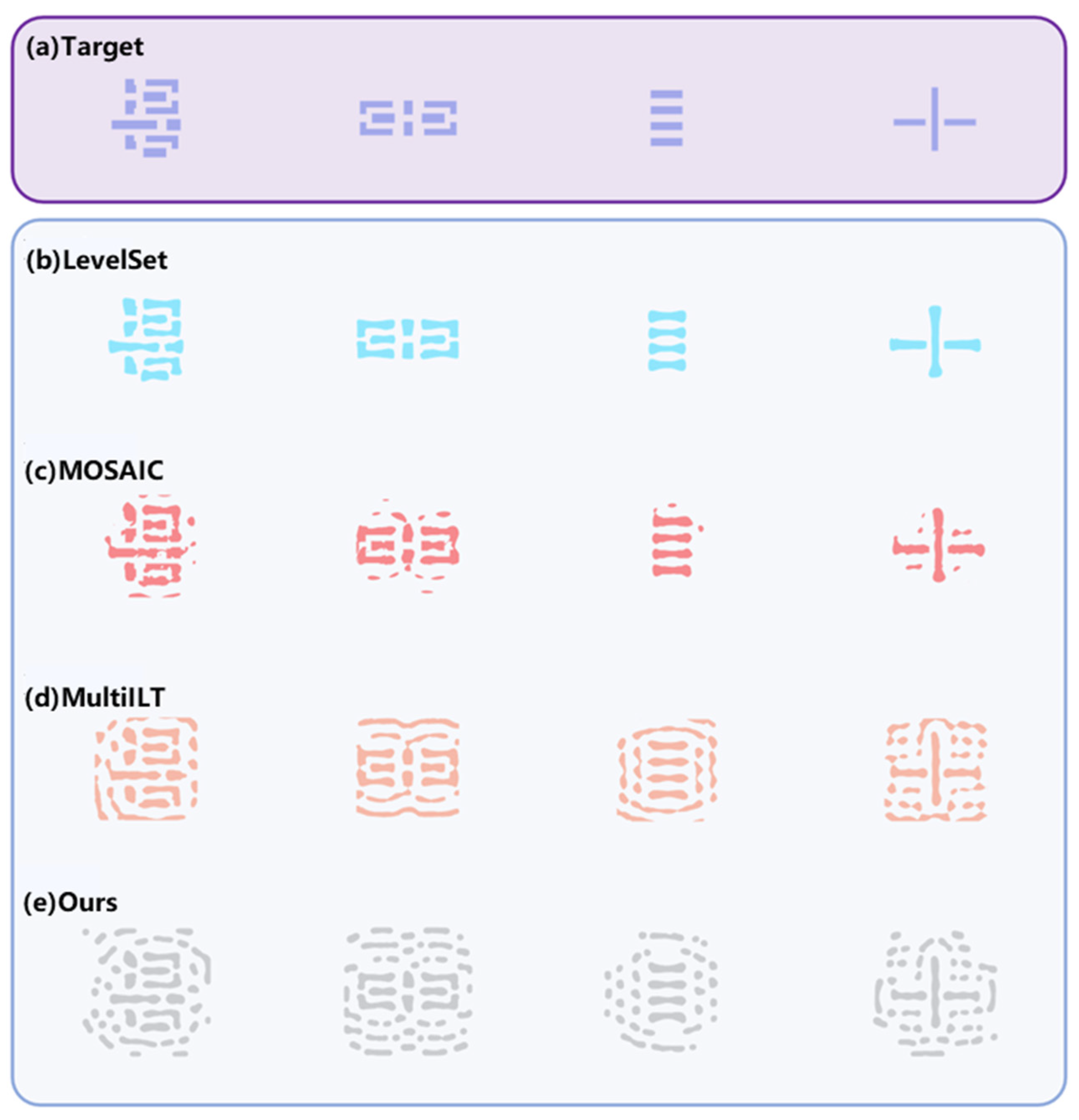
In the comparative experiment, our method employs a spacing constraint of 10 nm and a feature size (linewidth) constraint of 40 nm. Figure 7 presents the results of optimized mask patterns for various methods on complex layouts. The top row shows the target pattern used in ILT, while the subsequent rows depict the optimized masks obtained by LevelSet [44], MOSAIC [45], MultiILT [46], and our proposed method, respectively. Visually, LevelSet only optimizes the main features without generating any Sub-Resolution Assist Features (SRAFs). The MOSAIC method introduces some SRAFs, but they appear irregular and lack manufacturability. In contrast, MultiILT, which adopts a hierarchical optimization strategy, achieves improved pattern fidelity and enhanced manufacturability. However, it still produces certain features that violate MRC rules.
Compared to these existing approaches, our proposed method demonstrates a clear improvement in manufacturability. The generated SRAFs are well-structured and fully compliant with the specified MRC requirements.
From the metrics presented in Table 1, the superiority of our proposed method becomes more evident. Before delving into the comparisons, let us first define the metrics used:
  • MSE: Represents the L2 loss as defined in Equation (3);
  • PVB (Process Variation Bandwidth): Characterizes manufacturing process robustness by calculating the maximum contour separation area between the outermost contour I P R P , o u t and the innermost contour I P R P , i n under various process conditions;
    P V B = | | I P R P , o u t I P R P , i n | | 2 2
  • EPE: Measures the critical dimension at predefined edge test positions. If it exceeds a specified threshold, it is counted as an error;
  • For manufacturability, two metrics are employed: FVP (Feature Violation Penalty) and SVP (Space Violation Penalty), corresponding to the space constraint penalty and feature constraint penalty described in Algorithm 2.
Given that the LevelSet and MOSAIC methods exhibit poor manufacturability, their FVP and SVP metrics are not analyzed here. Overall, our proposed method demonstrates superior performance across all metrics. Specifically, in terms of MSE, our method shows an average improvement of approximately 6.2% over the next best method, MultiILT, while maintaining a comparable PVB. Regarding manufacturability, our method achieves FVP and SVP values that are 3.7% and 4.5% better than those of MultiILT, respectively. This indicates that our approach successfully integrates MRCs into ILT, thereby enhancing the manufacturability of the optimized masks.

5. Conclusions

In this work, we propose a hierarchical pixel-based inverse lithography technology framework, addressing the current challenges and advancements in ILT algorithm development. By considering mask optimization with manufacturability constraints and optimization limits, we introduce two key innovations. First, a corner-rounding-inspired target retargeting strategy is developed to mitigate over-optimization during the ILT process. This approach significantly enhances both convergence efficiency and final result quality, as evidenced by experimental results showing a 17% improvement in post-convergence performance for the grating pattern. For complex patterns, it improves by 6.2% averagely. Second, we incorporate MRC requirements into the ILT workflow through differentiable top-hat and bottom-hat operations. This ensures a balanced trade-off between pattern fidelity and manufacturability while enabling flexibility to generate solutions tailored to specific MRC complexity levels. However, the current manufacturability cost function does not account for full-chip optimization scenarios, particularly MRC violations at tile boundaries. Future work will focus on extending the framework to address these cross-tile manufacturability challenges, thereby improving scalability and robustness in large-scale photomask design.

Author Contributions

Formal analysis, H.S.; simulation design, H.S., Q.Z. and J.Z. (Jie Zhou); software, H.S. and Q.Z.; writing—original draft preparation, H.S.; writing—review and editing, H.S., Q.Z. and J.Z. (Ji Zhou); supervision, J.G., C.J. and J.L. All authors have read and agreed to the published version of the manuscript.

Funding

This work was supported by the Sichuan Provincial Regional Innovation Cooperation Project (2024YFHZ0189), the Sichuan Provincial Science Fund for Distinguished Young Scholars (2024NSFJQ0027), and the Sichuan Science and Technology Program (2024ZHCG0179).

Data Availability Statement

All data are included in the study.

Conflicts of Interest

The authors declare no conflicts of interest.

References

  1. Molesky, S.; Lin, Z.; Piggott, A.Y.; Jin, W.; Vucković, J.; Rodriguez, A.W. Inverse Design in Nanophotonics. Nat. Photonics 2018, 12, 659–670. [Google Scholar] [CrossRef]
  2. Bogaerts, W.; Chrostowski, L. Silicon Photonics Circuit Design: Methods, Tools and Challenges. Laser Photonics Rev. 2018, 12, 1700237. [Google Scholar] [CrossRef]
  3. Zeng, Q.; Zhao, Z.; Lei, H.; Wang, P. A Deep Learning Approach for Inverse Design of Gradient Mechanical Metamaterials. Int. J. Mech. Sci. 2023, 240, 107920. [Google Scholar] [CrossRef]
  4. Granchi, N.; Intonti, F.; Florescu, M.; García, P.D.; Gurioli, M.; Arregui, G. Q-Factor Optimization of Modes in Ordered and Disordered Photonic Systems Using Non-Hermitian Perturbation Theory. ACS Photonics 2023, 10, 2808–2815. [Google Scholar] [CrossRef]
  5. Yu, G.; Mao, X.; Ding, H.; Yang, F.; Wang, X. Inverse-Designed Polarization-Insensitive Metasurface Holography Fabricated by Nanoimprint Lithography. Opt. Lett. 2024, 49, 6845. [Google Scholar] [CrossRef]
  6. Mack, C.A. Thirty Years of Lithography Simulation. In Proceedings of the Optical Microlithography XVIII, San Jose, CA, USA, 27 February–4 March 2005; SPIE: Bellingham, WA, USA, 2005; Volume 5754, p. 1. [Google Scholar]
  7. Liu, A.C. Burn Jeng Lin A Study of Projected Optical Images for Typical IC Mask Patterns Illuminated by Partially Coherent Light. IEEE Trans. Electron Devices 1983, 30, 1251–1263. [Google Scholar] [CrossRef]
  8. Otto, O.W.; Henderson, R.C. Integrating Proximity Effect Corrections with Photomask Data Preparation. In Proceedings of the SPIE’s 1995 Symposium on Microlithography, Santa Clara, CA, USA, 19–24 February 1995; Brunner, T.A., Ed.; SPIE: Bellingham, WA, USA, 1995; pp. 184–191. [Google Scholar]
  9. Ma, X.; Arce, G.R. Computational Lithography; Wiley series in pure and applied optics; Wiley: Hoboken, NJ, USA, 2010; ISBN 978-0-470-59697-5. [Google Scholar]
  10. Stirniman, J.P.; Rieger, M.L. Fast Proximity Correction with Zone Sampling. In Proceedings of the SPIE’s 1994 Symposium on Microlithography, San Jose, CA, USA, 27 February–4 March 1994; Brunner, T.A., Ed.; SPIE: Bellingham, WA, USA, 1994; pp. 294–301. [Google Scholar]
  11. Cobb, N.B.; Zakhor, A.; Miloslavsky, E.A. Mathematical and CAD Framework for Proximity Correction. In Proceedings of the SPIE’s 1996 International Symposium on Microlithography, Santa Clara, CA, USA, 10–15 March 1996; Fuller, G.E., Ed.; SPIE: Bellingham, WA, USA, 1996; pp. 208–222. [Google Scholar]
  12. Ma, X.; Li, Y.; Dong, L. Mask Optimization Approaches in Optical Lithography Based on a Vector Imaging Model. J. Opt. Soc. Am. A 2012, 29, 1300. [Google Scholar] [CrossRef]
  13. Ma, X.; Zhao, X.; Wang, Z.; Li, Y.; Zhao, S.; Zhang, L. Fast Lithography Aerial Image Calculation Method Based on Machine Learning. Appl. Opt. 2017, 56, 6485. [Google Scholar] [CrossRef]
  14. Villaret, A.; Tritchkov, A.; Entradas, J.; Yesilada, E. Inverse Lithography Technique for Advanced CMOS Nodes. In Proceedings of the SPIE Advanced Lithography, San Jose, CA, USA, 24–28 February 2013; Conley, W., Ed.; SPIE: Bellingham, WA, USA, 2013; p. 86830E. [Google Scholar]
  15. Pang, L. Inverse Lithography Technology: 30 Years from Concept to Practical, Full-Chip Reality. J. Micro/Nanopatterning Mater. Metrol. 2021, 20, 030901. [Google Scholar] [CrossRef]
  16. Granik, Y. Fast Pixel-Based Mask Optimization for Inverse Lithography. J. Micro/Nanolithogr. MEMS MOEMS 2006, 5, 043002. [Google Scholar] [CrossRef]
  17. Yu, J.-C.; Yu, P. Impacts of Cost Functions on Inverse Lithography Patterning. Opt. Express 2010, 18, 23331. [Google Scholar] [CrossRef] [PubMed]
  18. Xiong, W.; Zhang, J.; Tsai, M.-C.; Wang, Y.; Yu, Z. An Analytic Gradient-Based Inverse Lithography Approach for Partially-Coherent Double-Exposure Lithography. J. Comput. Theor. Nanosci. 2010, 7, 157–164. [Google Scholar] [CrossRef]
  19. Jia, N.; Lam, E.Y. Stochastic Gradient Descent for Robust Inverse Photomask Synthesis in Optical Lithography. In Proceedings of the 2010 IEEE International Conference on Image Processing, Hong Kong, China, 26–29 September 2010; IEEE: Piscataway, NJ, USA, 2010; pp. 4173–4176. [Google Scholar]
  20. Ma, X.; Arce, G.R. Pixel-Based OPC Optimization Based on Conjugate Gradients. Opt. Express 2011, 19, 2165. [Google Scholar] [CrossRef]
  21. Scranton, G.; Bhargava, S.; Ganapati, V.; Yablonovitch, E. Single Spherical Mirror Optic for Extreme Ultraviolet Lithography Enabled by Inverse Lithography Technology. Opt. Express 2014, 22, 25027. [Google Scholar] [CrossRef]
  22. Wang, L.; Li, S.; Wang, X.; Yan, G.; Yang, C. Pixelated Source Optimization for Optical Lithography via Particle Swarm Optimization. J. Micro/Nanolithogr. MEMS MOEMS 2016, 15, 013506. [Google Scholar] [CrossRef]
  23. Wei, P.; Li, Y.; Li, T.; Sheng, N.; Li, E.; Sun, Y. Multi-Objective Defocus Robust Source and Mask Optimization Using Sensitive Penalty. Appl. Sci. 2019, 9, 2151. [Google Scholar] [CrossRef]
  24. Fang, P.-H.; Chen, Y.-S.; Wu, J.-S.; Yu, P. Inverse Reticle Optimization with Quantum Annealing and Hybrid Solvers. IEEE Access 2024, 12, 33069–33078. [Google Scholar] [CrossRef]
  25. Chen, W.; Ma, X.; Zhang, S. Bandwidth-Aware Fast Inverse Lithography Technology Using Nesterov Accelerated Gradient. Opt. Express 2024, 32, 42639. [Google Scholar] [CrossRef]
  26. Poonawala, A.; Milanfar, P. Mask Design for Optical Microlithography—An Inverse Imaging Problem. IEEE Trans. Image Process. 2007, 16, 774–788. [Google Scholar] [CrossRef]
  27. Zhou, J.; Zhang, Q.; Sun, H.; Jin, C.; Zhou, J.; Liu, J. Frequency-Decoupled Dual-Stage Inverse Lithography Optimization via Hierarchical Sampling and Morphological Enhancement. Micromachines 2025, 16, 515. [Google Scholar] [CrossRef]
  28. Banerjee, S.; Li, Z.; Nassif, S.R. ICCAD-2013 CAD Contest in Mask Optimization and Benchmark Suite. In Proceedings of the 2013 IEEE/ACM International Conference on Computer-Aided Design (ICCAD), San Jose, CA, USA, 18–21 November 2013; IEEE: Piscataway, NJ, USA, 2013; pp. 271–274. [Google Scholar]
  29. Poonawala, A.; Milanfar, P. A Pixel-Based Regularization Approach to Inverse Lithography. Microelectron. Eng. 2007, 84, 2837–2852. [Google Scholar] [CrossRef]
  30. Jia, N.; Lam, E.Y. Pixelated Source Mask Optimization for Process Robustness in Optical Lithography. Opt. Express 2011, 19, 19384. [Google Scholar] [CrossRef] [PubMed]
  31. Ma, X. Resolution Enhancement Optimization Methods in Optical Lithography with Improved Manufacturability. J. Micro/Nanolithogr. MEMS MOEMS 2011, 10, 023009. [Google Scholar] [CrossRef]
  32. Zhao, X.; Chu, C. Line Search-Based Inverse Lithography Technique for Mask Design. VLSI Des. 2012, 2012, 589128. [Google Scholar] [CrossRef]
  33. Gao, J.-R.; Xu, X.; Yu, B.; Pan, D.Z. MOSAIC. In Proceedings of the 51st Annual Design Automation Conference, San Francisco, CA, USA, 1–5 June 2014; pp. 1–6. [Google Scholar] [CrossRef]
  34. Jiang, B.; Liu, L.; Ma, Y.; Zhang, H.; Yu, B.; Young, E.F.Y. Neural-ILT. In Proceedings of the 59th ACM/IEEE Design Automation Conference, San Francisco, CA, USA, 10–14 July 2022; ACM: New York, NY, USA, 2022; pp. 967–972. [Google Scholar]
  35. Chen, G.; Li, S.; Wang, X. Efficient Optical Proximity Correction Based on Virtual Edge and Mask Pixelation with Two-Phase Sampling. Opt. Express 2021, 29, 17440. [Google Scholar] [CrossRef]
  36. Liu, X.; Xu, D.; Zeng, F.; Du, Y.; Xie, L.; Shen, Y.; Chen, H. Inverse Lithography with Adaptive Mask Complexity. In Proceedings of the 2024 Conference of Science and Technology for Integrated Circuits (CSTIC), Shanghai, China, 17–18 March 2024; IEEE: Piscataway, NJ, USA, 2024; pp. 1–3. [Google Scholar]
  37. Luo, K.; Shi, Z.; Yan, X.; Geng, Z. SVM Based Layout Retargeting for Fast and Regularized Inverse Lithography. J. Zhejiang Univ.-Sci. C 2014, 15, 390–400. [Google Scholar] [CrossRef]
  38. Yang, H.; Ren, H. GPU-Accelerated Inverse Lithography Towards High Quality Curvy Mask Generation. In Proceedings of the ISPD’25: International Symposium on Physical Design, Austin, TX, USA, 16–19 March 2025. [Google Scholar]
  39. Hendriks, C.L.L.; van Vliet, L.J. Basic Morphological Operations, Band-Limited Images and Sampling. In Scale Space Methods in Computer Vision, Proceedings of the 4th International Conference, Isle of Skye, UK, 10–12 June 2003; Lecture Notes in Computer Science; Griffin, L.D., Lillholm, M., Eds.; Springer: Berlin/Heidelberg, Germany, 2003; pp. 313–324. [Google Scholar]
  40. Sakata, W.; Yamasaki, K.; Narukawa, S.; Hayashi, N. Mask Rule Check for Inspection of Leading-Edge Photomask. In Proceedings of the SPIE Photomask Technology, Monterey, CA, USA, 3–7 October 2005; SPIE: Bellingham, WA, USA, 2005; Volume 5992, p. 59924E. [Google Scholar]
  41. Kato, K.; Taniguchi, Y.; Nishizawa, K.; Endo, M.; Inoue, T.; Hagiwara, R.; Yasaka, A. Mask Rule Check Using Priority Information of Mask Patterns. In Proceedings of the SPIE Photomask Technology, Monterey, CA, USA, 17–21 September 2007; Naber, R.J., Kawahira, H., Eds.; SPIE: Bellingham, WA, USA, 2007; p. 67304F. [Google Scholar]
  42. Gonzalez, R.; Woods, R. Digital Image Processing, 4th ed.; Pearson: New York, NY, USA, 2017; ISBN 978-0-13-335672-4. [Google Scholar]
  43. Comer, M.L.; Delp, E.J. Morphological Operations. In The Colour Image Processing Handbook; Sangwine, S.J., Horne, R.E.N., Eds.; Springer: Boston, MA, USA, 1998; pp. 210–227. ISBN 978-1-4615-5779-1. [Google Scholar]
  44. Yu, Z.; Chen, G.; Ma, Y.; Yu, B. A GPU-Enabled Level Set Method for Mask Optimization. In Proceedings of the 2021 Design, Automation & Test in Europe Conference & Exhibition (DATE), Grenoble, France, 1–5 February 2021. [Google Scholar]
  45. Gao, J.-R.; Xu, X.; Yu, B.; Pan, D.Z. MOSAIC: Mask Optimizing Solution with Process Window Aware Inverse Correction. In Proceedings of the 2014 51st ACM/EDAC/IEEE Design Automation Conference (DAC), San Francisco, CA, USA, 1–5 June 2014. [Google Scholar]
  46. Sun, S.; Yang, F.; Yu, B.; Shang, L.; Zeng, X. Efficient ILT via Multi-Level Lithography Simulation. In Proceedings of the 2023 60th ACM/IEEE Design Automation Conference (DAC), San Francisco, CA, USA, 9–13 July 2023; IEEE: Piscataway, NJ, USA, 2023; pp. 1–6. [Google Scholar]
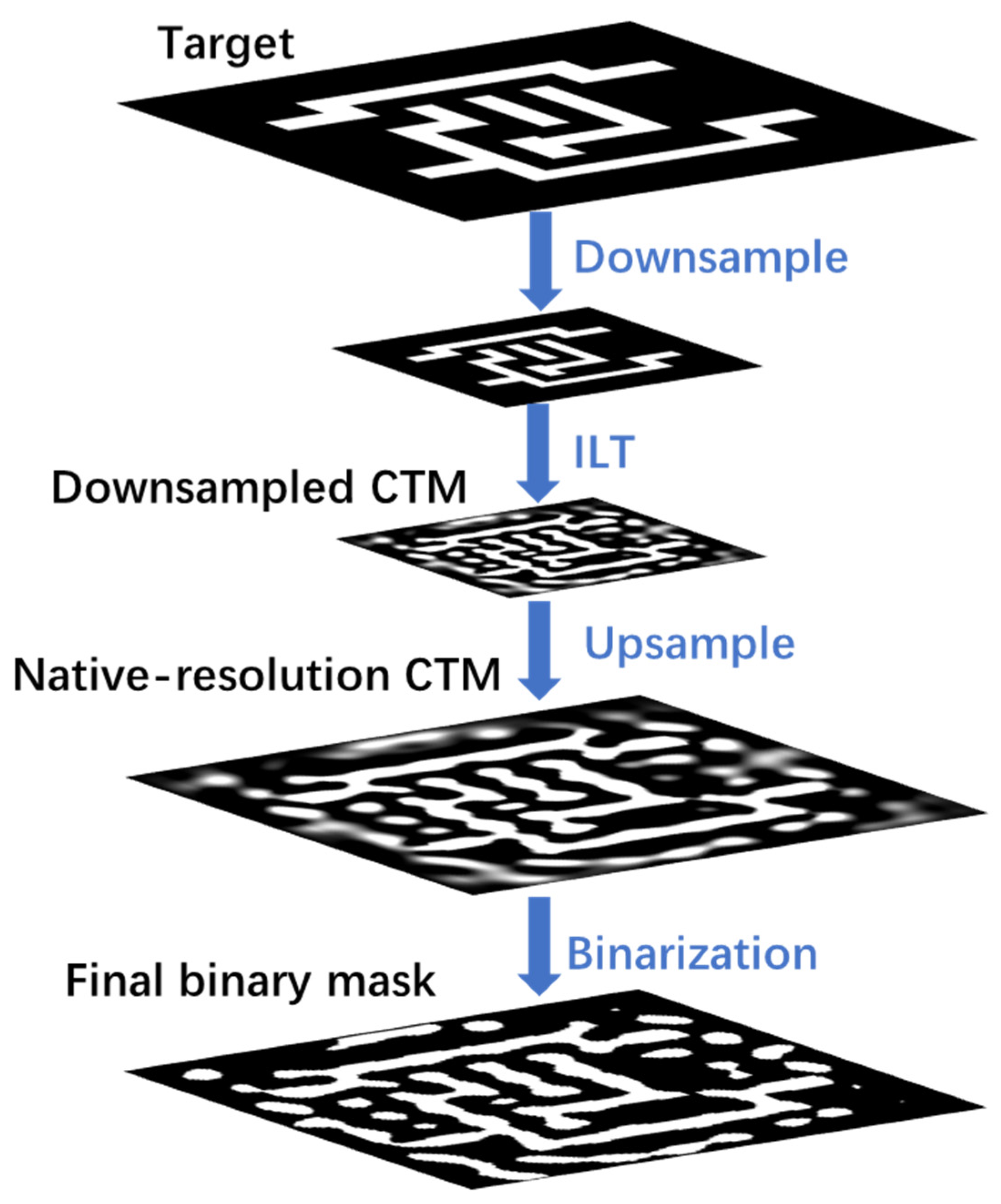
Figure 1. Hierarchical ILT optimization flowchart.
Micromachines 16 00798 g001
Figure 2. (a) The target design, (b) Corner region marked in red, and (c) their L2 loss iterations in ILT without corner rounding.
Micromachines 16 00798 g002
Figure 3. (a) The edge pixels, (b) the retargeted mask, and (c) comparison of their L2 loss iterations.
Micromachines 16 00798 g003
Figure 4. Examples of mask rule checks (MRCs) for a curvilinear mask. (a) The minimum circle can slide entirely within and around the mask, so that it is MRC-clean. (b) The internal checking fails, and it violates the minimum feature size setting. (c) The external checking fails, and it violates the minimum spacing setting.
Micromachines 16 00798 g004
Figure 6. The optimized masks by different space and feature width constraints.
Micromachines 16 00798 g006
Figure 7. Simulation results for different patterns. (a) Target; (b) LevelSet; (c) MOSAIC; (d) MultiILT; (e) ours.
Micromachines 16 00798 g007
Table 1. Comparison of ICCAD13 results with other ILT methods.
CaseLevelSetMOSAICMultiILTOurs
MSEPVEPEMSEPVEPEMSEPVEPEFVPSVPMSE PVEPEFVPSVP
145,52057,468648,89655,028839,53344,887322822339,98444,380344020
233,57149,680137,32746,019432,51637,374011025029,96236,806011031
378,69590,7483981,32786,6854765,31575,0112346486562,37472,1971512020
418,04027,710216,40926,3582909921,48403899905864822,74609925
538,22659,035237,81057,472030,01548,6960232171628,90847,368028414
635,96254,163036,70652,566033,40042,7880591735129,84442,23007126
730,54248,173229,52047,598217,41936,2410341857314,09836,41405619
814,25225,043114,29124,268111,55218,98704922108310,29219,63107028
943,39068,229147,36764,932237,21954,7920277770734,43554,33606916
10891920,8780895019,8710718014,97905270382719315,79603319
Avg34,71250,1135.435,86035,8606.628,32539,5242.6365648626,57439,1901.813522
Disclaimer/Publisher’s Note: The statements, opinions and data contained in all publications are solely those of the individual author(s) and contributor(s) and not of MDPI and/or the editor(s). MDPI and/or the editor(s) disclaim responsibility for any injury to people or property resulting from any ideas, methods, instructions or products referred to in the content.