
Ultra-Low-Voltage Capacitive Micromachined Ultrasonic Transducers with Increased Output Pressure Due to Piston-Structured Plates

 ,
,
Abstract
:
1. Introduction
1.1. State of the Art

| Lateral Geometry (m) | Gap, Insulator (nm) | Sound Pressure (MPa) | Pull-In Voltage (V) | Technology | Center Frequency (MHz), fBW (%) | |
|---|---|---|---|---|---|---|
| Guldiken et al. [20] | Rectangular, a/d = 50% (width) | 120, 250 | NA | 129 | Surface micromachining | 8, 136 ( parylene coating) |
| Huang et al. [21] | Squared, a/d = 58% | 440, NA | 1.28 | 65 | 2× wafer bonding | 2.5, 150 |
| Wong et al. [22] | Circular, a/d = 80% | 400, 600 | 1 | 140 | Wafer bonding | 3, NA |
| Jeong et al. [23] | Non-trivial, ind. clamped | 350, NA | NA | 95 | 2× wafer bonding | 3.37, NA |
| Lee et al. [24] | Non-trivial, posts in substrate | 150, 200 | 1.88 | 78 | Wafer bonding | 1.8, 81 |
| Yu et al. [25] | Circular, ring stiff. (PI op.) | 300, 2 × 150 | kPa | 55 | Surface micromachining | 6.1, 52.5 |
| Park et al. [16] | Circular, low-voltage design | 50, 80 | NA | 10 | Wafer-bonding | 7.4, NA |
| This paper | Circular, piston on-top | 120, 25 | 0.04 to 0.5 | 7.4 to 25 | Surface micromachining | 3.3 to 4.2, up to 135 |
2. Design and Fabrication
2.1. Design
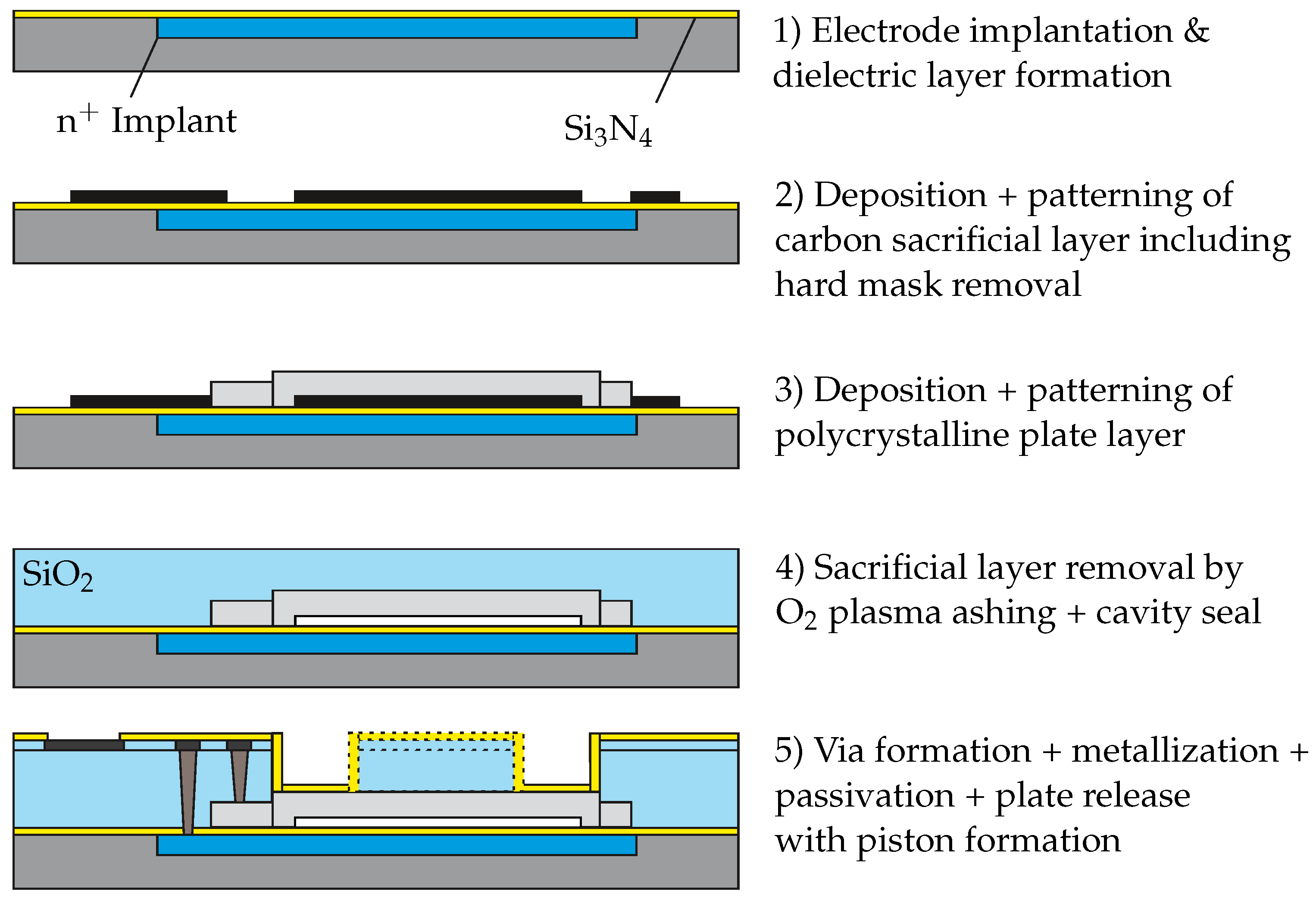
2.2. Fabrication
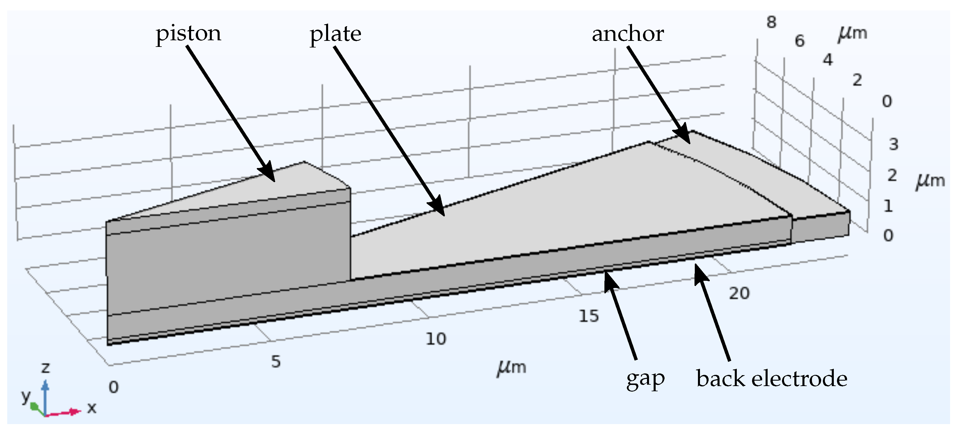
3. FEM Simulations
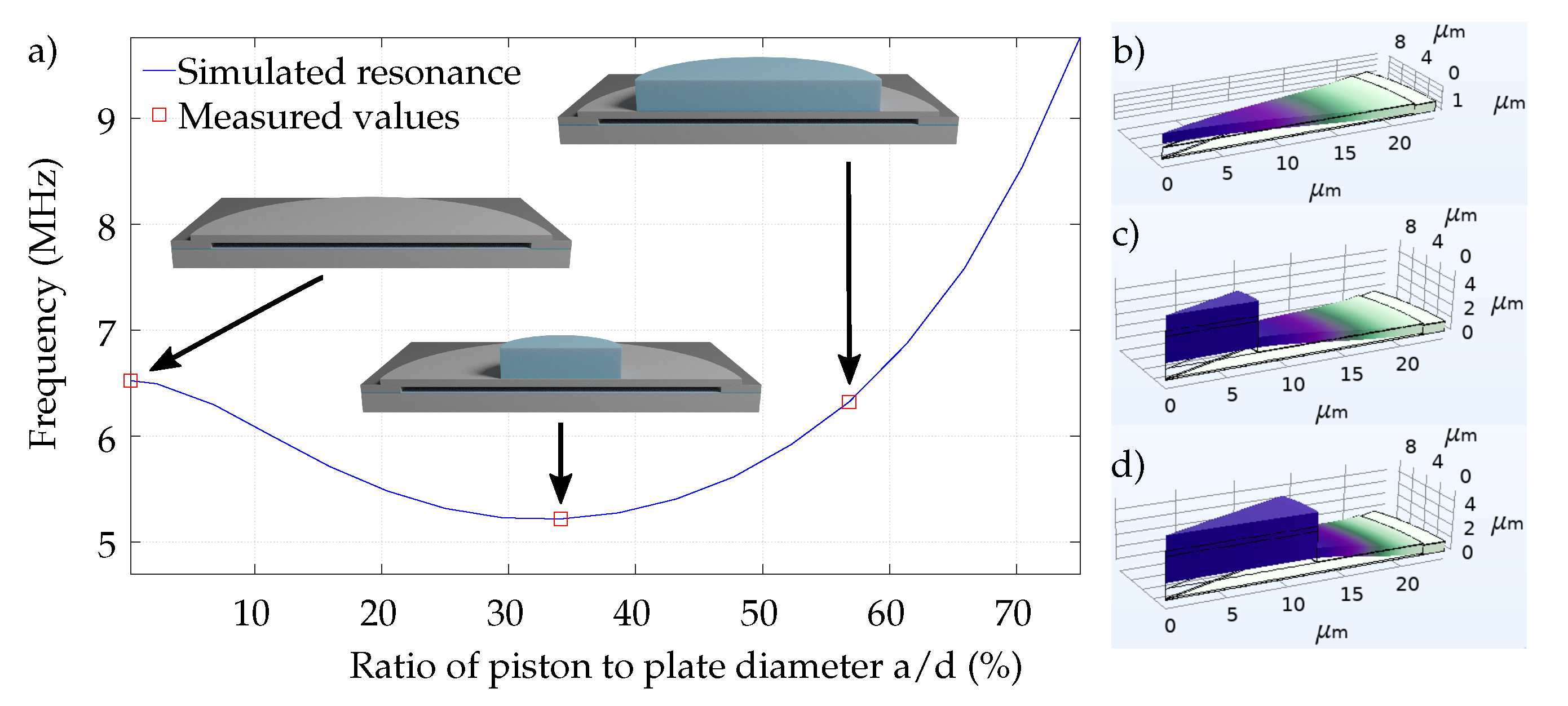
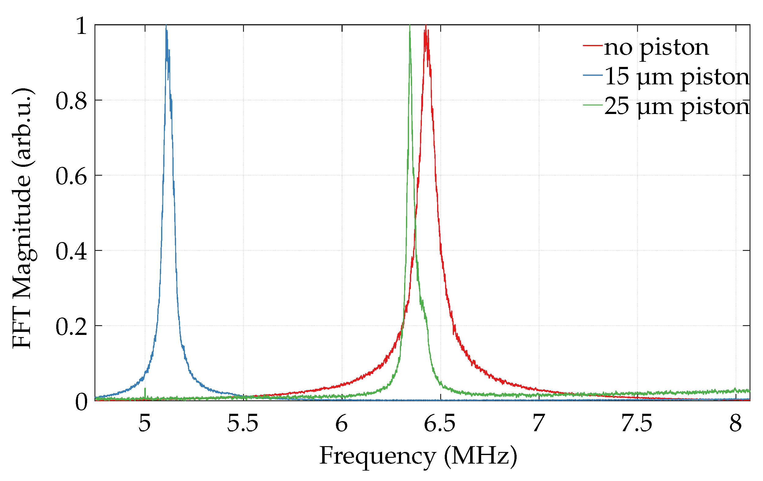
3.1. Resonance
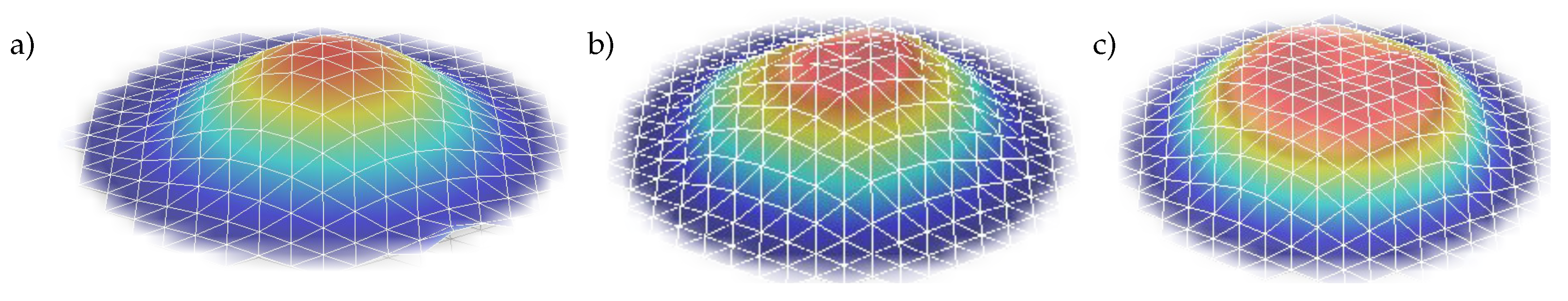
3.2. Modal Shape of Piston Movement
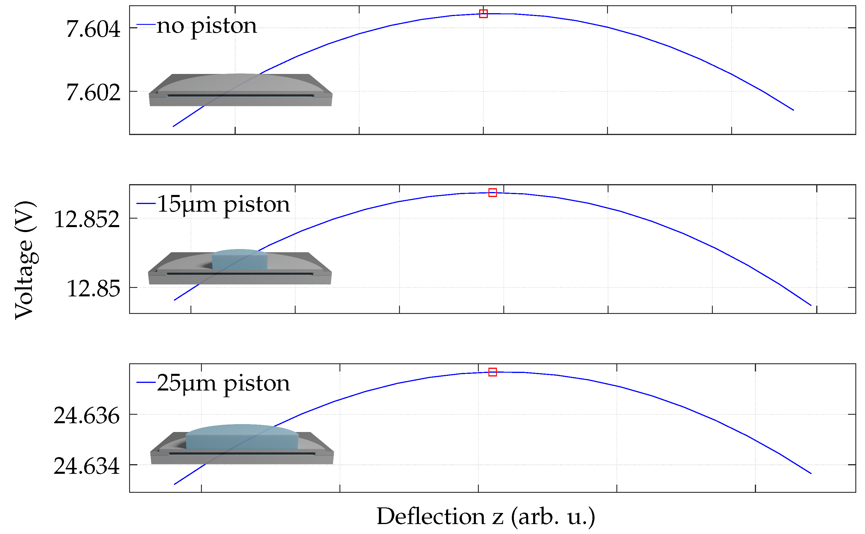
3.3. Pull-In
4. Characterization Measurement Results
4.1. Mechanical Characterization
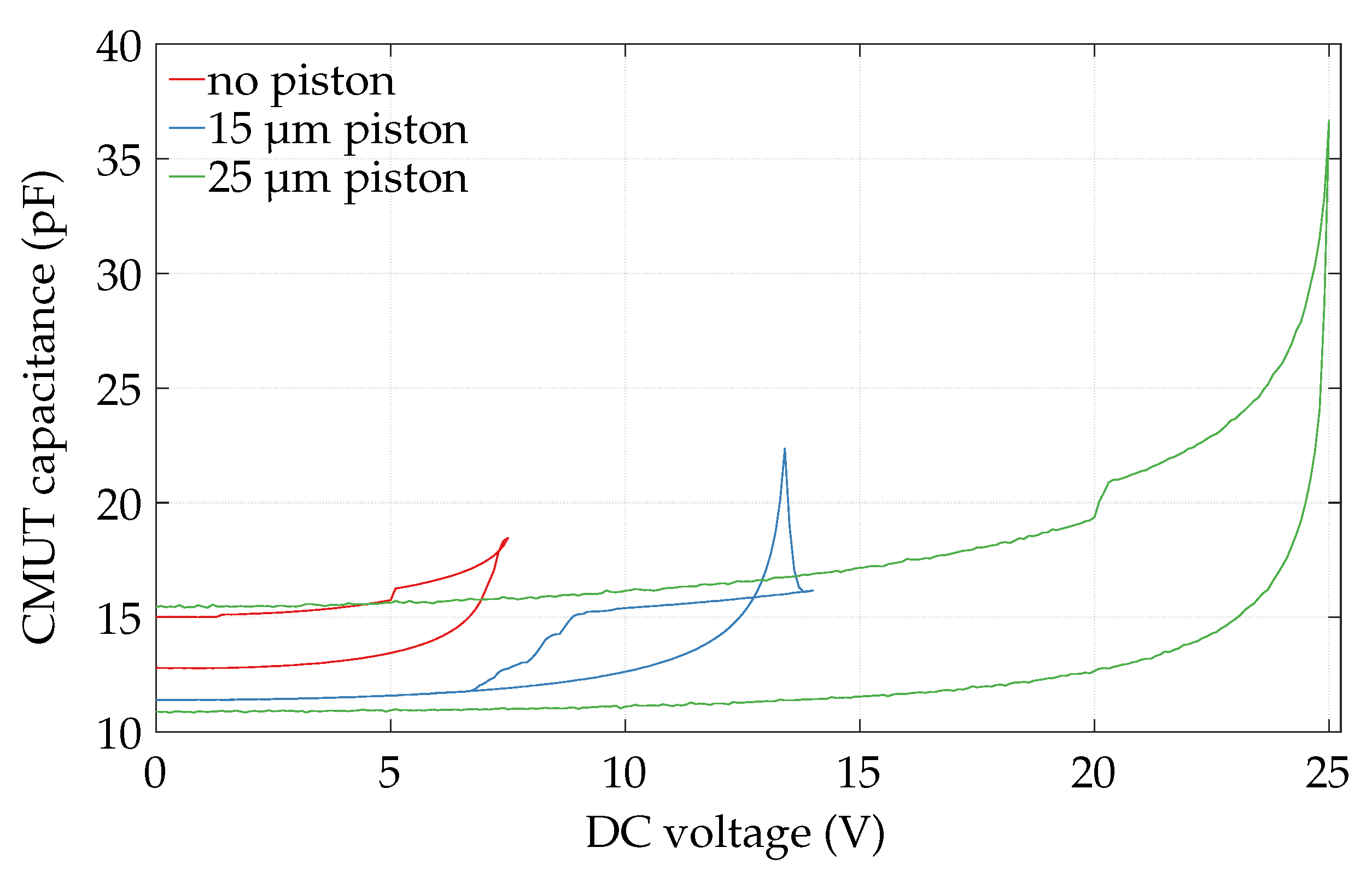
4.2. Electrical Characterization
4.3. Acoustic Characterization
5. Conclusions
Author Contributions
Funding
Institutional Review Board Statement
Informed Consent Statement
Data Availability Statement
Acknowledgments
Conflicts of Interest
References
- Haller, M.; Khuri-Yakub, B. A surface micromachined electrostatic ultrasonic air transducer. IEEE Ultrason. Symp. 1994, 2, 1241–1244. [Google Scholar] [CrossRef]
- Wong, S.H.; Watkins, R.D.; Kupnik, M.; Pauly, K.B.; Khuri-yakub, B.T. Feasibility of MR-temperature mapping of ultrasonic heating from a CMUT. IEEE Trans. Ultrason. Ferroelectr. Freq. Control 2008, 55, 811–818. [Google Scholar] [CrossRef] [PubMed] [Green Version]
- Bhuyan, A.; Choe, J.W.; Lee, B.C.; Wygant, I.O.; Nikoozadeh, A.; Oralkan, O.; Khuri-Yakub, B.T. Integrated Circuits for Volumetric Ultrasound Imaging With 2-D CMUT Arrays. IEEE Trans. Biomed. Circuits Syst. 2013, 7, 796–804. [Google Scholar] [CrossRef] [PubMed]
- Zangabad, R.P.; Bosch, J.G.; Mastik, F.; Beurskens, R.H.S.H.; Henneken, V.A.; Weekamp, J.W.; van der Steen, A.F.W.; van Soest, G. Real-Time Coded Excitation Imaging Using a CMUT-Based Side Looking Array for Intravascular Ultrasound. IEEE Trans. Ultrason. Ferroelectr. Freq. Control 2021, 68, 2048–2058. [Google Scholar] [CrossRef]
- Peng, C.; Wu, H.; Kim, S.; Dai, X.; Jiang, X. Recent Advances in Transducers for Intravascular Ultrasound (IVUS) Imaging. Sensors 2021, 21, 3540. [Google Scholar] [CrossRef]
- Degertekin, F.; Guldiken, R.; Karaman, M. Annular-ring CMUT arrays for forward-looking IVUS: Transducer characterization and imaging. IEEE Trans. Ultrason. Ferroelectr. Freq. Control 2006, 53, 474–482. [Google Scholar] [CrossRef]
- Nikoozadeh, A.; Wygant, D.J.; Lin, D.S.; Oralkan, O.; Ergun, A.S.; Stephens, D.N.; Thomenius, K.E.; Dentinger, A.M.; Wildes, D.; Akopyan, G.; et al. Forward-looking intracardiac ultrasound imaging using a 1-D CMUT array integrated with custom front-end electronics. IEEE Trans. Ultrason. Ferroelectr. Freq. Control 2008, 55, 2651–2660. [Google Scholar] [CrossRef] [Green Version]
- Vallet, M.; Varray, F.; Boutet, J.; Dinten, J.M.; Caliano, G.; Savoia, A.S.; Vray, D. Quantitative comparison of PZT and CMUT probes for photoacoustic imaging: Experimental validation. Photoacoustics 2017, 8, 48–58. [Google Scholar] [CrossRef]
- Wang, H.; Ma, Y.; Yang, H.; Jiang, H.; Ding, Y.; Xie, H. MEMS Ultrasound Transducers for Endoscopic Photoacoustic Imaging Applications. Micromachines 2020, 11, 928. [Google Scholar] [CrossRef]
- Pei, Y.; Zhang, G.; Zhang, Y.; Zhang, W. Breast Acoustic Parameter Reconstruction Method Based on Capacitive Micromachined Ultrasonic Transducer Array. Micromachines 2021, 12, 963. [Google Scholar] [CrossRef]
- Merbeler, F.; Anzinger, S.; Bretthauer, C.; Kupnik, M. Ultra-compact Clamp-on Liquid Level Sensor based on a Low-Voltage CMUT. In Proceedings of the IEEE Sensors, Rotterdam, The Netherlands, 25–28 October 2020; pp. 1–4. [Google Scholar] [CrossRef]
- Wang, M.; Chen, J. Volumetric Flow Measurement Using an Implantable CMUT Array. IEEE Trans. Biomed. Circuits Syst. 2011, 5, 214–222. [Google Scholar] [CrossRef] [PubMed]
- Hutchins, D.; Billson, D.; Bradley, R.; Ho, K. Structural health monitoring using polymer-based capacitive micromachined ultrasonic transducers (CMUTs). Ultrasonics 2011, 51, 870–877. [Google Scholar] [CrossRef]
- Butaud, P.; Bourbon, G.; Moal, P.L.; Joseph, E.; Verdin, B.; Ramasso, E.; Placet, V. CMUT sensors based on circular membranes array for SHM applications. In Proceedings of the Sensors and Smart Structures Technologies for Civil, Mechanical, and Aerospace Systems, Denver, CO, USA, 27 March 2019; Lynch, J.P., Huang, H., Sohn, H., Wang, K.W., Eds.; International Society for Optics and Photonics (SPIE): Bellingham, WA, USA, 2019; Volume 10970, pp. 641–648. [Google Scholar] [CrossRef] [Green Version]
- Nazemi, H.; Antony Balasingam, J.; Swaminathan, S.; Ambrose, K.; Nathani, M.U.; Ahmadi, T.; Babu Lopez, Y.; Emadi, A. Mass Sensors Based on Capacitive and Piezoelectric Micromachined Ultrasonic Transducers—CMUT and PMUT. Sensors 2020, 20, 2010. [Google Scholar] [CrossRef] [PubMed] [Green Version]
- Park, S.; Yoon, I.; Lee, S.; Kim, H.; Seo, J.W.; Chung, Y.; Unger, A.; Kupnik, M.; Lee, H.J. CMUT-based resonant gas sensor array for VOC detection with low operating voltage. Sens. Actuators B Chem. 2018, 273, 1556–1563. [Google Scholar] [CrossRef]
- Barauskas, D.; Pelenis, D.; Vanagas, G.; Viržonis, D.; Baltrušaitis, J. Methylated Poly(ethylene)imine Modified Capacitive Micromachined Ultrasonic Transducer for Measurements of CO2 and SO2 in Their Mixtures. Sensors 2019, 19, 3236. [Google Scholar] [CrossRef] [Green Version]
- Lamberti, N.; Caliano, G.; Iula, A.; Savoia, A.S. A high frequency cMUT probe for ultrasound imaging of fingerprints. Sens. Actuators A Phys. 2011, 172, 561–569. [Google Scholar] [CrossRef]
- Brenner, K.; Ergun, A.S.; Firouzi, K.; Rasmussen, M.F.; Stedman, Q.; Khuri-Yakub, B.P. Advances in Capacitive Micromachined Ultrasonic Transducers. Micromachines 2019, 10, 152. [Google Scholar] [CrossRef] [Green Version]
- Guldiken, R.O.; Zahorian, J.; Yamaner, F.Y.; Degertekin, F.L. Dual-electrode CMUT with non-uniform membranes for high electromechanical coupling coefficient and high bandwidth operation. IEEE Trans. Ultrason. Ferroelectr. Freq. Control 2009, 56, 1270–1276. [Google Scholar] [CrossRef] [Green Version]
- Huang, Y.; Zhuang, X.; Haeggstrom, E.O.; Ergun, A.S.; Cheng, C.H.; Khuri-Yakub, B.T. Capacitive micromachined ultrasonic transducers with piston-shaped membranes: Fabrication and experimental characterization. IEEE Trans. Ultrason. Ferroelectr. Freq. Control 2009, 56, 136–145. [Google Scholar] [CrossRef]
- Wong, S.; Kupnik, M.; Pauly, K.B.; Khuri-Yakub, B. Capacitive micromachined ultrasonic transducer (CMUT) for MR-guided noninvasive therapeutic ultrasound applications. In Proceedings of the International Solid-State Sensors, Actuators and Microsystems Conference, Denver, CO, USA, 21–25 June 2009; pp. 354–357. [Google Scholar] [CrossRef]
- Jeong, B.G.; Kim, D.K.; Hong, S.W.; Chung, S.W.; Shin, H.J. Performance and reliability of new CMUT design with improved efficiency. Sens. Actuators A Phys. 2013, 199, 325–333. [Google Scholar] [CrossRef]
- Lee, B.; Nikoozadeh, A.; Park, K.; Khuri-Yakub, B. High-Efficiency Output Pressure Performance Using Capacitive Micromachined Ultrasonic Transducers with Substrate-Embedded Springs. Sensors 2018, 18, 2520. [Google Scholar] [CrossRef] [PubMed] [Green Version]
- Yu, Y.; Wang, J.; Liu, X.; Pun, S.H.; Zhang, S.; Cheng, C.H.; Lei, K.F.; Vai, M.I.; Mak, P.U. Experimental Characterization of an Embossed Capacitive Micromachined Ultrasonic Transducer Cell. Micromachines 2020, 11, 217. [Google Scholar] [CrossRef] [PubMed] [Green Version]
- Senlik, M.; Olcum, S.; Atalar, A. Improved performance of cMUT with nonuniform membranes. IEEE Ultrason. Symp. 2005, 1, 597–600. [Google Scholar] [CrossRef]
- Wygant, I.O.; Kupnik, M.; Khuri-Yakub, B.T. An Analytical Model for Capacitive Pressure Transducers With Circular Geometry. J. Microelectromech. Syst. 2018, 27, 448–456. [Google Scholar] [CrossRef]
- Kaajakari, V. Practical MEMS; Small Gear Publishing: Las Vegas, NV, USA, 2009. [Google Scholar]
- Morse, P.M.; Ingard, K.U. Theoretical Acoustics; Princeton University Press: Princeton, NJ, USA, 1987. [Google Scholar]
- Fraser, J.D.; Reynolds, P. Finite element method for determination of electromechanical coupling coefficient for piezoelectric and capacitive micromachined ultrasonic transducers. J. Acoust. Soc. Am. 2000, 108, 2599. [Google Scholar] [CrossRef]
- Berlincourt, D. Piezoelectric Crystals and Ceramics; Springer: Boston, MA, USA, 1971; pp. 63–124. [Google Scholar] [CrossRef]
- Yaralioglu, G.G.; Ergun, A.S.; Bayram, B.; Haeggstrom, E.; Khuri-Yakub, B.T. Calculation and measurement of electromechanical coupling coefficient of capacitive micromachined ultrasonic transducers. IEEE Trans. Ultrason. Ferroelectr. Freq. Control 2003, 50, 449–456. [Google Scholar] [CrossRef]
- Beissner, K. Exact Integral Expression for the Diffraction Loss of a Circular Piston Source. Acta Acust. United Acust. 1981, 49, 212–217. [Google Scholar]
- Goldstein, A.; Gandhi, D.; O’Brien, W. Diffraction effects in hydrophone measurements. IEEE Trans. Ultrason. Ferroelectr. Freq. Control 1998, 45, 972–979. [Google Scholar] [CrossRef]
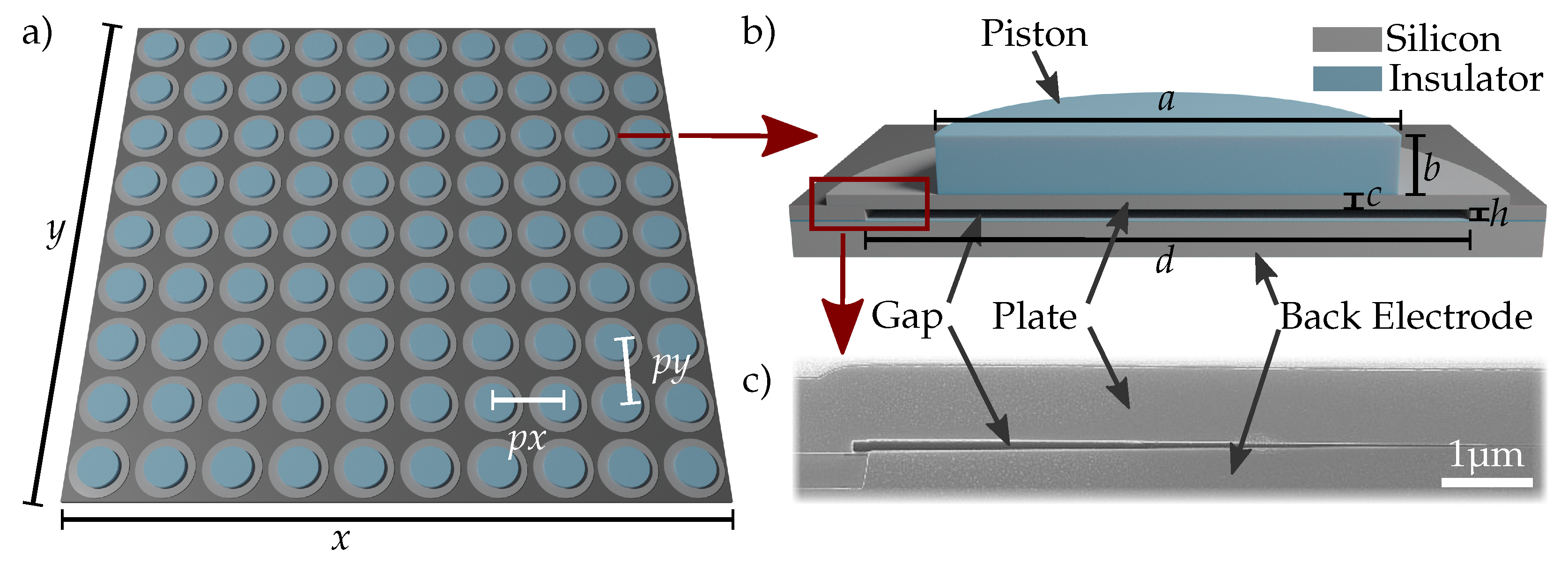
| Plate and piston geometry | Circular |
| Plate thickness c | 800 nm |
| Plate diameter d | 44 |
| Vacuum gap height h | 120 nm |
| Vacuum gap insulator height | 25 nm |
| Piston sizes a | 0, 15, 25 |
| Piston height b | |
| Plate matrix | 9 × 10 |
| Active area on chip x, y | 500 × 600 2 = mm2 |
| Pitch ; | ; 56 |
| Piston (m) | Simulation | Measurement | Deviation (%) | |
|---|---|---|---|---|
| Resonance | 0 | 6.52 | 6.43 ± 0.024 | +1.4 |
| frequency (MHz) | 15 | 5.22 | 5.11 ± 0.012 | +2.1 |
| 25 | 6.32 | 6.34 ± 0.004 | −0.3 | |
| 0 | 7.60 | 7.4 ± 0.1 | +2.7 | |
| Pull-in voltage (V) | 15 | 12.85 | 13.4 ± 0.1 | −4.2 |
| 25 | 24.63 | 25.0 ± 0.1 | −1.5 |
Publisher’s Note: MDPI stays neutral with regard to jurisdictional claims in published maps and institutional affiliations. |
© 2022 by the authors. Licensee MDPI, Basel, Switzerland. This article is an open access article distributed under the terms and conditions of the Creative Commons Attribution (CC BY) license (https://creativecommons.org/licenses/by/4.0/).
Share and Cite
Merbeler, F.; Wismath, S.; Haubold, M.; Bretthauer, C.; Kupnik, M. Ultra-Low-Voltage Capacitive Micromachined Ultrasonic Transducers with Increased Output Pressure Due to Piston-Structured Plates. Micromachines 2022, 13, 676. https://doi.org/10.3390/mi13050676
Merbeler F, Wismath S, Haubold M, Bretthauer C, Kupnik M. Ultra-Low-Voltage Capacitive Micromachined Ultrasonic Transducers with Increased Output Pressure Due to Piston-Structured Plates. Micromachines. 2022; 13(5):676. https://doi.org/10.3390/mi13050676
Chicago/Turabian StyleMerbeler, Fabian, Sonja Wismath, Marco Haubold, Christian Bretthauer, and Mario Kupnik. 2022. "Ultra-Low-Voltage Capacitive Micromachined Ultrasonic Transducers with Increased Output Pressure Due to Piston-Structured Plates" Micromachines 13, no. 5: 676. https://doi.org/10.3390/mi13050676
APA StyleMerbeler, F., Wismath, S., Haubold, M., Bretthauer, C., & Kupnik, M. (2022). Ultra-Low-Voltage Capacitive Micromachined Ultrasonic Transducers with Increased Output Pressure Due to Piston-Structured Plates. Micromachines, 13(5), 676. https://doi.org/10.3390/mi13050676