
Design and Optimization of Piezoelectric Cantilever Beam Vibration Energy Harvester


Abstract
:1. Introduction
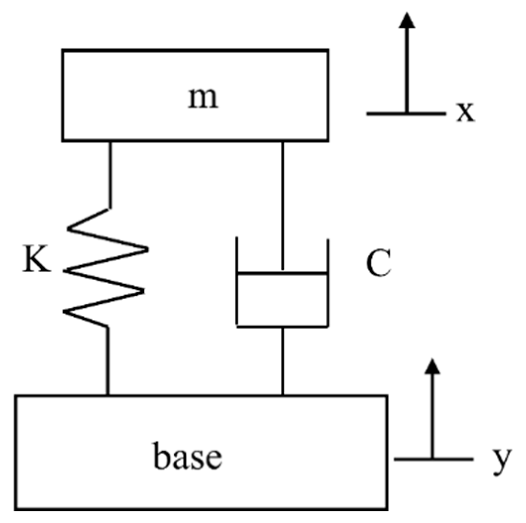
2. Design and Simulation
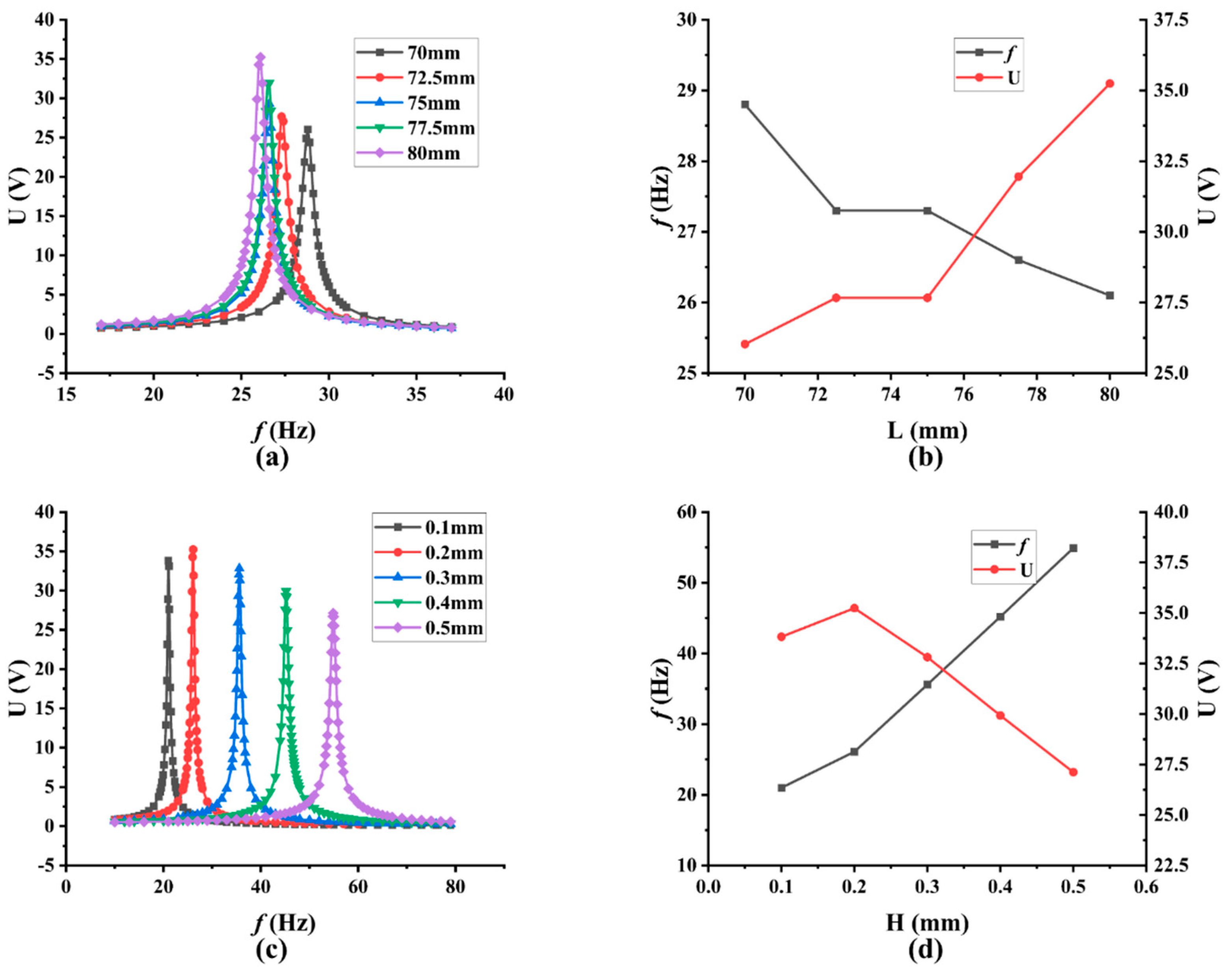
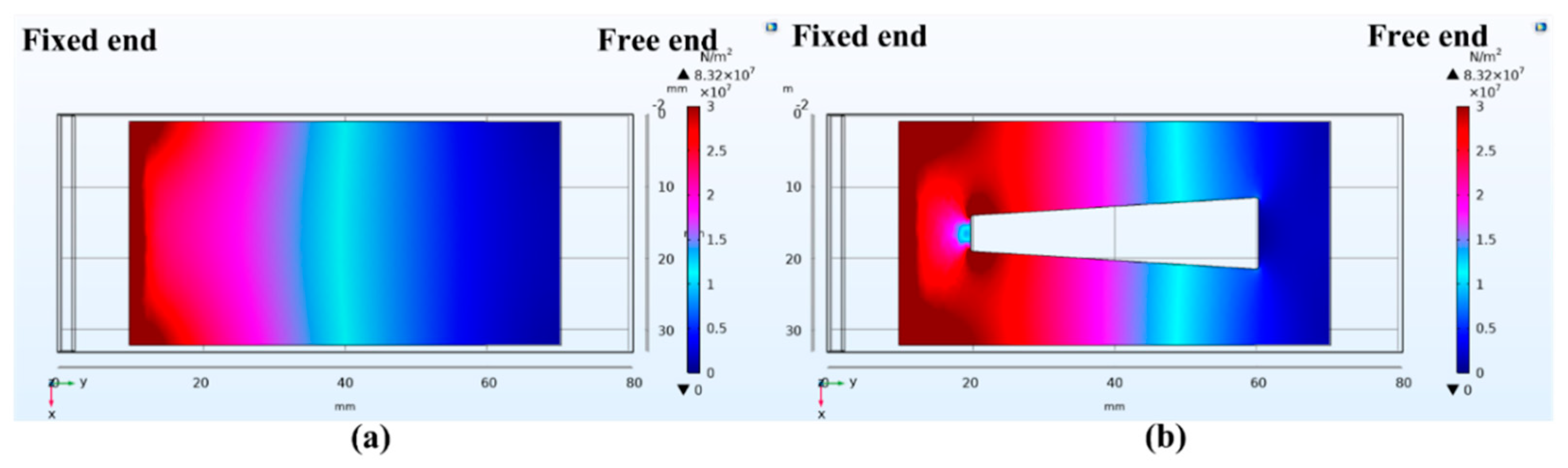
3. Optimization
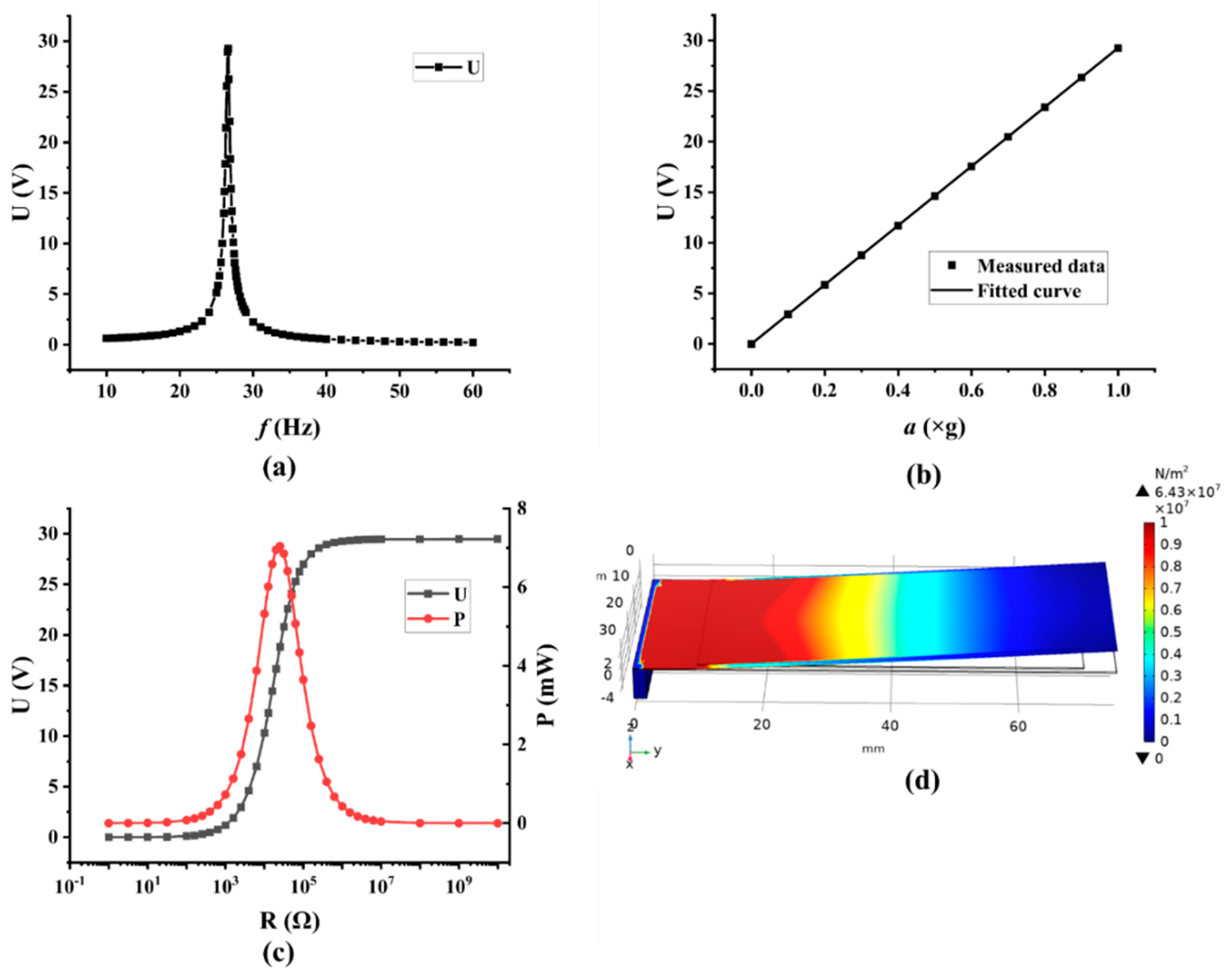
4. Experiment
5. Conclusions
Author Contributions
Funding
Institutional Review Board Statement
Informed Consent Statement
Data Availability Statement
Conflicts of Interest
References
- Shirvanimoghaddam, M.; Abolhasani, M.M.; Farhangi, M.; Barsari, V.Z.; Liu, H.; Dohler, M.; Naebe, M. Towards a Green and Self-Powered Internet of Things Using Piezoelectric Energy Harvesting. IEEE Access 2019, 7, 94533–94556. [Google Scholar] [CrossRef]
- Won, S.S.; Seo, H.; Kawahara, M.; Glinsek, S.; Lee, J.; Kim, Y.; Jeong, C.K.; Kingon, A.I.; Kim, S.-H. Flexible vibrational energy harvesting devices using strain-engineered perovskite piezoelectric thin films. Nano Energy 2019, 55, 182–192. [Google Scholar] [CrossRef]
- Ali, F.; Raza, W.; Li, X.; Gul, H.; Kim, K.-H. Piezoelectric energy harvesters for biomedical applications. Nano Energy 2019, 57, 879–902. [Google Scholar] [CrossRef]
- Liu, H.; Zhong, J.; Lee, C.; Lee, S.-W.; Lin, L. A comprehensive review on piezoelectric energy harvesting technology: Materials, mechanisms, and applications. Appl. Phys. Rev. 2018, 5, 041306. [Google Scholar] [CrossRef]
- Kim, H.S.; Kim, J.-H.; Kim, J. A review of piezoelectric energy harvesting based on vibration. Int. J. Precis. Eng. Manuf. 2011, 12, 1129–1141. [Google Scholar] [CrossRef]
- Kumar, T.; Kumar, R.; Chauhan, V.S.; Twiefel, J. Finite-Element Analysis of a Varying-Width Bistable Piezoelectric Energy Harvester. Energy Technol. 2015, 3, 1243–1249. [Google Scholar] [CrossRef]
- Leinonen, M.; Juuti, J.; Jantunen, H.; Palosaari, J. Energy Harvesting with a Bimorph Type Piezoelectric Diaphragm Multilayer Structure and Mechanically Induced Pre-stress. Energy Technol. 2016, 4, 620–624. [Google Scholar] [CrossRef]
- Zhu, J.; Niu, X.; Hou, X.; He, J.; Chou, X.; Xue, C.; Zhang, W. Highly Reliable Real-time Self-powered Vibration Sensor Based on a Piezoelectric Nanogenerator. Energy Technol. 2018, 6, 781–789. [Google Scholar] [CrossRef]
- Chen, J.; Oh, S.K.; Nabulsi, N.; Johnson, H.; Wang, W.; Ryou, J.-H. Biocompatible and sustainable power supply for self-powered wearable and implantable electronics using III-nitride thin-film-based flexible piezoelectric generator. Nano Energy 2018, 57, 670–679. [Google Scholar] [CrossRef]
- Sodano, H.A.; Inman, D.J.; Park, G. A Review of Power Harvesting from Vibration Using Piezoelectric Materials. Shock Vib. Dig. 2004, 36, 197–205. [Google Scholar] [CrossRef] [Green Version]
- Liu, W.; Han, M.; Meng, B.; Sun, X.; Huang, X.; Zhang, H. Low frequency wide bandwidth MEMS energy harvester based on spiral-shaped PVDF cantilever. Sci. China Technol. Sci. 2014, 57, 1068–1072. [Google Scholar] [CrossRef]
- Shahab, S.; Zhao, S.; Erturk, A. Soft and hard piezoelectric ceramics and single crystals for random vibration energy harvesting. Energy Technol. 2018, 6, 935–942. [Google Scholar] [CrossRef]
- Ju, S.; Ji, C.-H. Impact-based piezoelectric vibration energy harvester. Appl. Energy 2018, 214, 139–151. [Google Scholar] [CrossRef]
- Jiang, X.; Li, Y.; Li, J.; Wang, J.; Yao, J. Piezoelectric energy harvesting from traffic-induced pavement vibrations. J. Renew. Sustain. Energy 2014, 6, 043110. [Google Scholar] [CrossRef]
- Sezer, N.; Koç, M. A comprehensive review on the state-of-the-art of piezoelectric energy harvesting. Nano Energy 2021, 80, 105567. [Google Scholar] [CrossRef]
- Proto, A.; Penhaker, M.; Conforto, S.; Schmid, M. Nanogenerators for Human Body Energy Harvesting. Trends Biotechnol. 2017, 35, 610–624. [Google Scholar] [CrossRef]
- Akkaya Oy, S. A piezoelectric energy harvesting from the vibration of the airflow around a moving vehicle. Int. Trans. Electr. Energy Syst. 2020, 30, e12655. [Google Scholar] [CrossRef]
- Uchino, K. Piezoelectric energy harvesting systems—Essentials to successful developments. Energy Technol. 2018, 6, 829–848. [Google Scholar] [CrossRef]
- Li, R.; Yu, Y.; Zhou, B.; Guo, Q.; Li, M.; Pei, J. Harvesting energy from pavement based on piezoelectric effects: Fabrication and electric properties of piezoelectric vibrator. J. Renew. Sustain. Energy 2018, 10, 054701. [Google Scholar] [CrossRef]
- Wang, X.; Wilson, P.R.; Leite, R.B.; Chen, G.; Freitas, H.; Asadi, K.; Smits, E.C.P.; Katsouras, I.; Rocha, P.R.F. An Energy Harvester for Low-Frequency Electrical Signals. Energy Technol. 2020, 8, 2000114. [Google Scholar] [CrossRef]
- Galchev, T.V.; Mccullagh, J.; Peterson, R.L.; Najafi, K. Harvesting traffic-induced vibrations for structural health monitoring of bridges. J. Micromech. Microeng. 2011, 21, 104005. [Google Scholar] [CrossRef] [Green Version]
- Amin Karami, M.; Inman, D.J. Powering pacemakers from heartbeat vibrations using linear and nonlinear energy harvesters. Appl. Phys. Lett. 2012, 100, 042901. [Google Scholar] [CrossRef]
- Beeby, S.P.; Tudor, M.J.; White, N. Energy harvesting vibration sources for microsystems applications. Meas. Sci. Technol. 2006, 17, R175. [Google Scholar] [CrossRef]
- Vullers, R.; van Schaijk, R.; Doms, I.; Van Hoof, C.; Mertens, R. Micropower energy harvesting. Solid State Electron. 2009, 53, 684–693. [Google Scholar] [CrossRef]
- Tan, Y.; Dong, Y.; Wang, X. Review of MEMS electromagnetic vibration energy harvester. J. Microelectromech. Syst. 2016, 26, 1–16. [Google Scholar] [CrossRef]
- Pillatsch, P.; Yeatman, E.M.; Holmes, A.S. A piezoelectric frequency up-converting energy harvester with rotating proof mass for human body applications. Sens. Actuators A Phys. 2014, 206, 178–185. [Google Scholar] [CrossRef]
- Miao, P.; Mitcheson, P.; Holmes, A.; Yeatman, E.; Green, T.; Stark, B. MEMS inertial power generators for biomedical applications. Microsyst. Technol. 2006, 12, 1079–1083. [Google Scholar] [CrossRef] [Green Version]
- Wong, C.H.; Dahari, Z. Development of vibration-based piezoelectric raindrop energy harvesting system. J. Electron. Mater. 2017, 46, 1869–1882. [Google Scholar] [CrossRef]
- Zhang, Z.; Zhang, X.; Rasim, Y.; Wang, C.; Du, B.; Yuan, Y. Design, modelling and practical tests on a high-voltage kinetic energy harvesting (EH) system for a renewable road tunnel based on linear alternators. Appl. Energy 2016, 164, 152–161. [Google Scholar] [CrossRef]
- Zhen, L.; Wang, Y.; Bai, S. Generation characteristics of piezoelectric vibrator driven by groove cam: Simulation and experimental analysis. J. Renew. Sustain. Energy 2016, 8, 064701. [Google Scholar]
- Costa, P.; Nunes-Pereira, J.; Pereira, N.; Castro, N.; Gonçalves, S.; Lanceros-Mendez, S. Recent progress on piezoelectric, pyroelectric, and magnetoelectric polymer-based energy-harvesting devices. Energy Technol. 2019, 7, 1800852. [Google Scholar] [CrossRef]
- Karadag, C.V.; Ertarla, S.; Topaloglu, N.; Okyar, A.F. Optimization of beam profiles for improved piezoelectric energy harvesting efficiency. Struct. Multidiscip. Optim. 2020, 63, 631–643. [Google Scholar] [CrossRef]
- Wu, H.; Tang, L.; Yang, Y.; Soh, C. A novel two-degrees-of-freedom piezoelectric energy harvester. J. Intell. Mater. Syst. Struct. 2012, 24, 357–368. [Google Scholar] [CrossRef]
- Xiong, Y.; Song, F.; Leng, X. A piezoelectric cantilever-beam energy harvester (PCEH) with a rectangular hole in the metal substrate. Microsyst. Technol. 2020, 26, 801–810. [Google Scholar] [CrossRef]
- Wang, L.; Tong, X.; Yang, H.; Wei, Y.; Miao, Y. Design and analysis of a hollow triangular piezoelectric cantilever beam harvester for vibration energy collection. Int. J. Pavement Res. Technol. 2019, 12, 259–268. [Google Scholar] [CrossRef]
- Wang, B.; Zhang, C.; Lai, L.; Dong, X.; Li, Y. Design, Manufacture and Test of Piezoelectric Cantilever-Beam Energy Harvesters with Hollow Structures. Micromachines 2021, 12, 1090. [Google Scholar] [CrossRef] [PubMed]
- Yang, Z.; Zhou, S.; Zu, J.; Inman, D. High-performance piezoelectric energy harvesters and their applications. Joule 2018, 2, 642–697. [Google Scholar] [CrossRef] [Green Version]
- Dong, X.; Yi, Z.; Kong, L.; Tian, Y.; Liu, J.; Yang, B. Design, fabrication, and characterization of bimorph micromachined harvester with asymmetrical PZT films. J. Microelectromechan. Syst. 2019, 28, 700–706. [Google Scholar] [CrossRef]
- Jin, L.; Gao, S.; Zhang, X.; Wu, Q. Output of MEMS Piezoelectric Energy Harvester of Double-Clamped Beams with Different Width Shapes. Materials 2020, 13, 2330. [Google Scholar] [CrossRef]
- Priya, S.; Ryu, J.; Park, C.-S.; Oliver, J.; Choi, J.-J.; Park, D.-S. Piezoelectric and Magnetoelectric Thick Films for Fabricating Power Sources in Wireless Sensor Nodes. Sensors 2009, 9, 6362–6384. [Google Scholar] [CrossRef] [Green Version]
- Priya, S. Advances in energy harvesting using low profile piezoelectric transducers. J. Electrocer. 2007, 19, 167–184. [Google Scholar] [CrossRef]
- Kong, C.S. A general maximum power transfer theorem. IEEE Trans. Educ. 1995, 38, 296–298. [Google Scholar] [CrossRef]
- He, J.; Wen, T.; Qian, S.; Zhang, Z.; Tian, Z.; Zhu, J.; Mu, J.; Hou, X.; Geng, W.; Cho, J.; et al. Triboelectric-piezoelectric-electromagnetic hybrid nanogenerator for high-efficient vibration energy harvesting and self-powered wireless monitoring system. Nano Energy 2018, 43, 326–339. [Google Scholar] [CrossRef]
- Leland, E.S.; Lai, E.M.; Wright, P.K. A self-powered wireless sensor for indoor environmental monitoring. In Wireless Networking Symposium; University of Texas at Austin Department of Electrical & Computer Engineerin: Austin, TX, USA, 2004. [Google Scholar]


| Structure | Electrode Layer | Piezoelectric Layer | Substrate Layer |
|---|---|---|---|
| Material | Ag | PZT-5H | copper |
| Density/(kg/m3) | 10,500 | 7500 | 8780 |
| Yang’s modulus/(1010 N/m2) | 83 | 5.6 | 11.2 |
| Poisson’s ratio | 0.37 | 0.36 | 0.35 |
| Title 1 | Piezoelectric Layer | Substrate Layer |
|---|---|---|
| Length/(mm) | 60 | 75 |
| Width/(mm) | 31 | 33 |
| Thickness/(mm) | 0.2 | 0.2 |
| Copper Substrate Size | Output | ||
|---|---|---|---|
| Length (mm) | Thickness (mm) | Resonance Frequency (Hz) | Peak Output Voltage (V) |
| 70 | 0.2 | 28.8 | 26.026 |
| 72.5 | 27.3 | 27.664 | |
| 75 | 26.6 | 29.272 | |
| 77.5 | 26.6 | 31.954 | |
| 80 | 26.1 | 35.243 | |
| 80 | 0.1 | 21 | 33.826 |
| 0.2 | 26.1 | 35.243 | |
| 0.3 | 35.6 | 32.816 | |
| 0.4 | 45.2 | 29.927 | |
| 0.5 | 54.9 | 27.121 | |
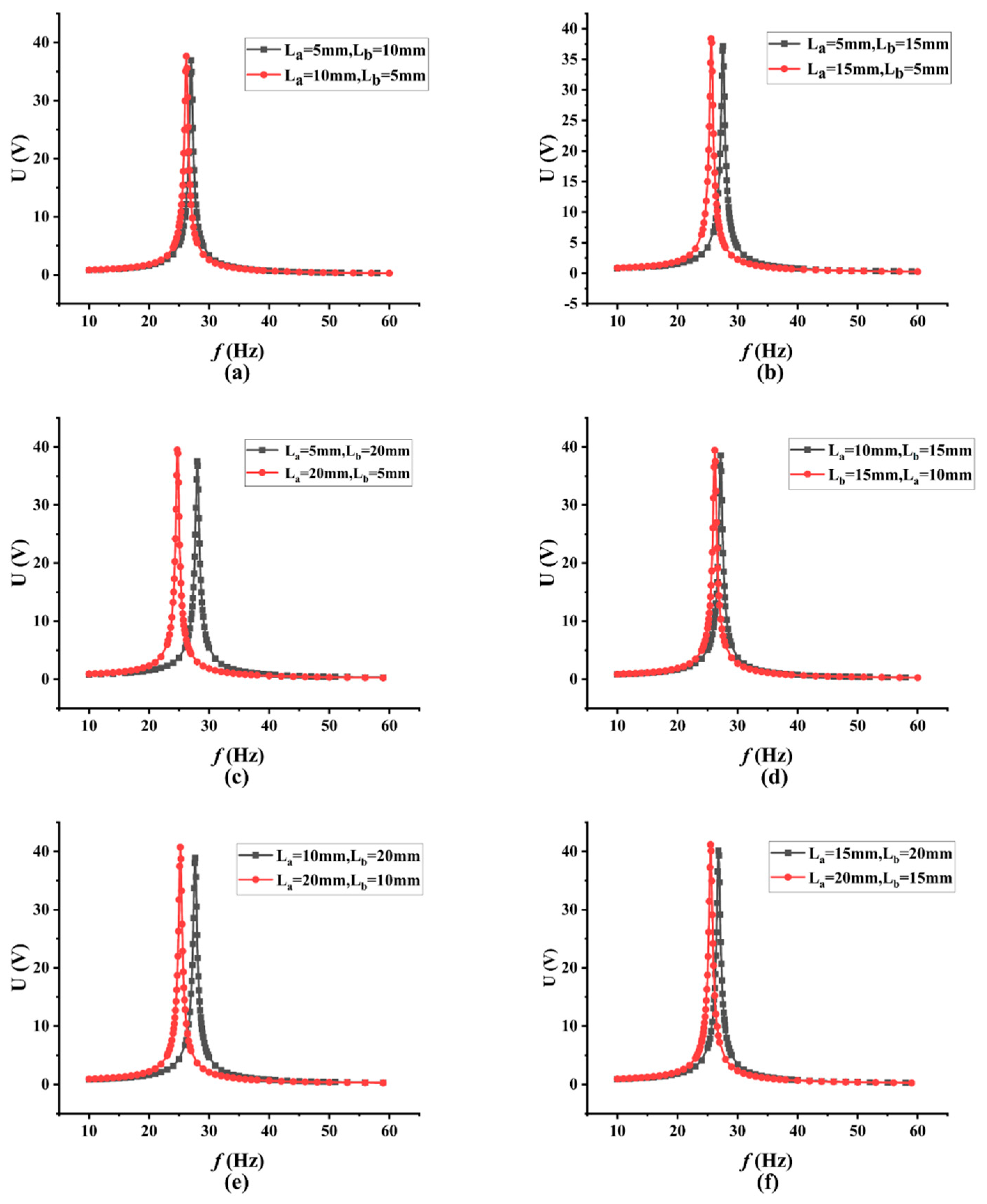
| Group | La (mm) | Lb (mm) | Resonance Frequency (Hz) | Peak Output Voltage (V) |
|---|---|---|---|---|
| 1 | 5 | 10 | 27.0 | 36.937 |
| 10 | 5 | 26.2 | 37.646 | |
| 2 | 5 | 15 | 27.6 | 37.147 |
| 15 | 5 | 25.6 | 38.385 | |
| 3 | 5 | 20 | 28.0 | 37.543 |
| 20 | 5 | 24.7 | 39.499 | |
| 4 | 10 | 15 | 27.2 | 38.562 |
| 15 | 10 | 26.2 | 39.441 | |
| 5 | 10 | 20 | 27.7 | 38.91 |
| 20 | 10 | 25.2 | 40.748 | |
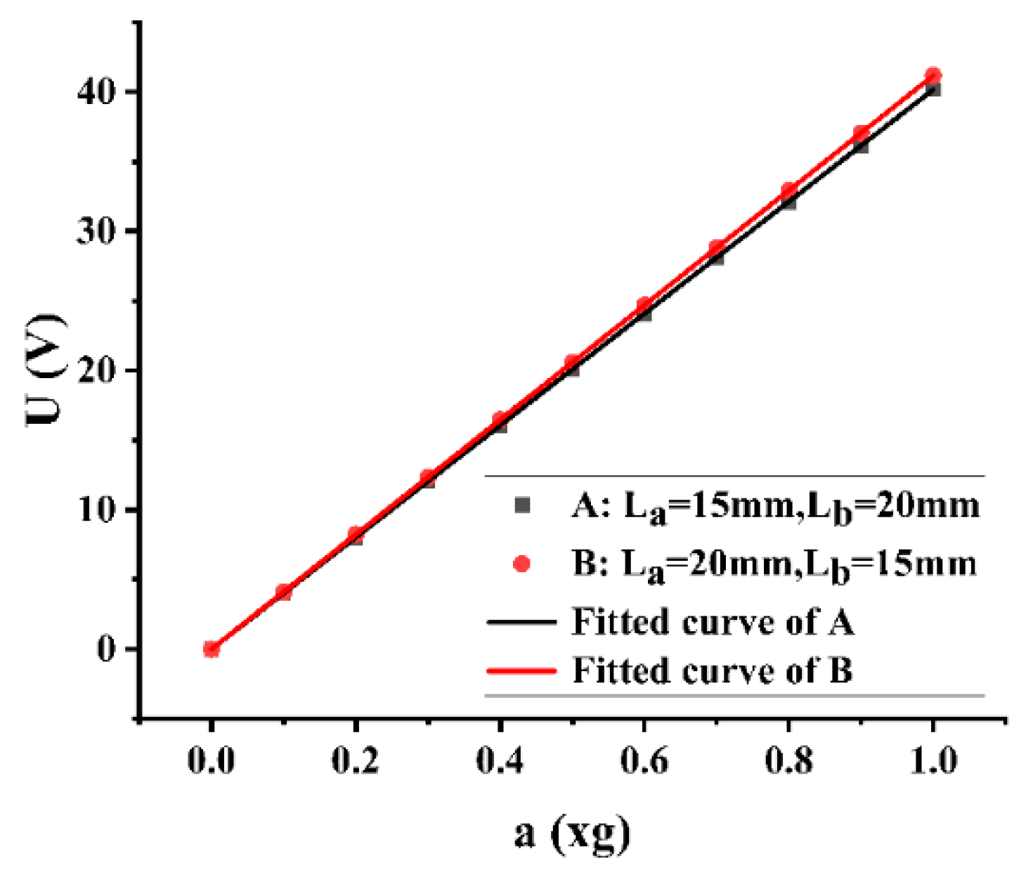
| 6 | 15 | 20 | 26.8 | 40.175 |
| 20 | 15 | 25.5 | 41.182 |
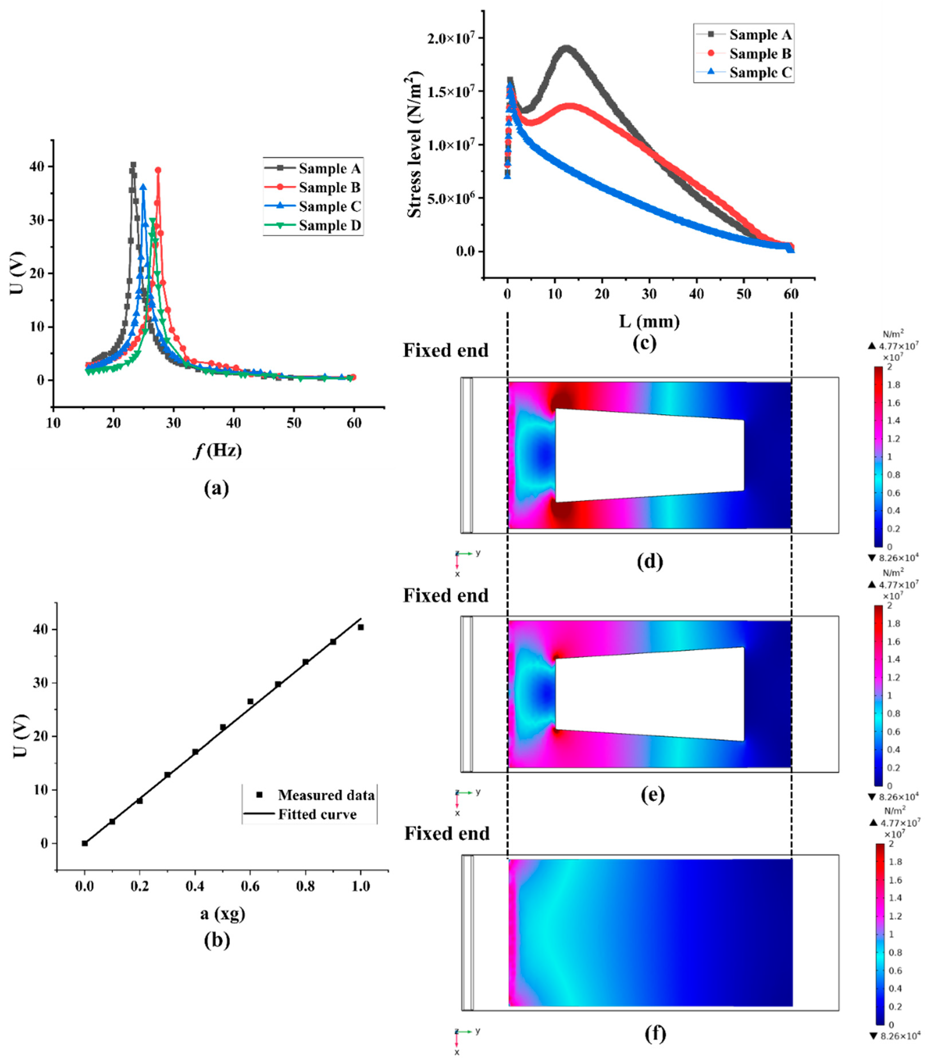
| Sample Number | Copper Substrate Size | Trapezoidal Hollow Hole | Resonance Frequency (Hz) | Peak Voltage Output (V) | ||
|---|---|---|---|---|---|---|
| Length (mm) | Thickness (mm) | La (mm) | Lb (mm) | |||
| A | 80 | 0.2 | 20 | 15 | 23.29 | 40.40 |
| B | 80 | 0.2 | 15 | 20 | 27.42 | 39.37 |
| C | 80 | 0.2 | unhollowed structure | 24.92 | 36.12 | |
| D | 75 | 0.2 | unhollowed structure | 26.52 | 30.00 | |
| Devices | Clock & Timer | Temperature & Humidity Sensors | Gas & Air Quality Sensors |
|---|---|---|---|
| Energy consumption (μW) | 0.1–1 | 1–10 | 10–100 |
Publisher’s Note: MDPI stays neutral with regard to jurisdictional claims in published maps and institutional affiliations. |
© 2022 by the authors. Licensee MDPI, Basel, Switzerland. This article is an open access article distributed under the terms and conditions of the Creative Commons Attribution (CC BY) license (https://creativecommons.org/licenses/by/4.0/).
Share and Cite
Xu, Q.; Gao, A.; Li, Y.; Jin, Y. Design and Optimization of Piezoelectric Cantilever Beam Vibration Energy Harvester. Micromachines 2022, 13, 675. https://doi.org/10.3390/mi13050675
Xu Q, Gao A, Li Y, Jin Y. Design and Optimization of Piezoelectric Cantilever Beam Vibration Energy Harvester. Micromachines. 2022; 13(5):675. https://doi.org/10.3390/mi13050675
Chicago/Turabian StyleXu, Qiuyu, Anran Gao, Yigui Li, and Yan Jin. 2022. "Design and Optimization of Piezoelectric Cantilever Beam Vibration Energy Harvester" Micromachines 13, no. 5: 675. https://doi.org/10.3390/mi13050675
APA StyleXu, Q., Gao, A., Li, Y., & Jin, Y. (2022). Design and Optimization of Piezoelectric Cantilever Beam Vibration Energy Harvester. Micromachines, 13(5), 675. https://doi.org/10.3390/mi13050675