Article

Understanding the Origin of Metal Gate Work Function Shift and Its Impact on Erase Performance in 3D NAND Flash Memories

by
Sivaramakrishnan Ramesh
*,
Arjun Ajaykumar
,
Lars-Åke Ragnarsson
,
Laurent Breuil
,
Gabriel Khalil El Hajjam
,
Ben Kaczer
,
Attilio Belmonte
,
Laura Nyns
,
Jean-Philippe Soulié
,
Geert Van den bosch
and
Maarten Rosmeulen
IMEC, Kapeldreef 75, B-3001 Leuven, Belgium
*
Author to whom correspondence should be addressed.
Micromachines 2021, 12(9), 1084; https://doi.org/10.3390/mi12091084
Submission received: 4 August 2021 / Revised: 1 September 2021 / Accepted: 1 September 2021 / Published: 8 September 2021
(This article belongs to the Special Issue Flash Memory Devices)

Abstract

:
We studied the metal gate work function of different metal electrode and high-k dielectric combinations by monitoring the flat band voltage shift with dielectric thicknesses using capacitance–voltage measurements. We investigated the impact of different thermal treatments on the work function and linked any shift in the work function, leading to an effective work function, to the dipole formation at the metal/high-k and/or high-k/SiO2 interface. We corroborated the findings with the erase performance of metal/high-k/ONO/Si (MHONOS) capacitors that are identical to the gate stack in three-dimensional (3D) NAND flash. We demonstrate that though the work function extraction is convoluted by the dipole formation, the erase performance is not significantly affected by it.

1. Introduction

When it comes to low-cost and large density non-volatile memory, three-dimensional (3D) NAND flash memory technology is the industry standard [1,2]. The memory stack used in 3D NAND is inspired by a typical SONOS memory cell, which allows easy vertical integration and is addressed by horizontal word lines (WL). To improve the bit density, the number of cells in the vertical 3D NAND string is increased. This requires the stacking of many WLs, which need to be as thin as possible to limit the total height and mechanical stress of the structure [3]. Tungsten (W) metal-based WL is currently being used by the industry. However, novel materials with lower resistivity are being considered as future candidates to reduce the high resistive-capacitive (RC) delay that results as a consequence of WL thinning and continued stacking of the WLs (i.e., downscaling the metal thickness) in the vertical direction.
Moreover, the WL metal can act as an enabler to improve the 3D NAND erase operation. It was shown that high work function metals, such as TiN and Ru, can delay the electron injection from the gate (i.e., electrons tunneling from the gate into the charge-trap layer), thereby improving the erase window [4]. It has also been demonstrated [5] that when a metal gate is used in combination with a thin high-k liner, such as Al2O3, HfO2, or ZrO2 (i.e., a Metal/High-k/ONO/Si (MHONOS) structure), the erase performance can be further improved. Figure 1 plots the erase saturation levels (lowest possible threshold voltage, VTH, shift achievable) for different scenarios, with and without a high-k liner, as simulated using our in-house developed 1D simulator [6]. The high-k liner helps to lower the injecting field for the electrons at the gate, and even proves to have a larger impact than the metal work function (WF). The erase is found to be penalized when the MHONOS stack is treated with a high thermal budget [3]. To thoroughly investigate the WL metal and high-k liner combination, and its effect on erase operation, metal work function extraction experiments have been proposed and studied in this work.
WF analysis of metal gate electrodes on high-k dielectrics, by monitoring flat-band voltage, VFB (or threshold voltage, VTH), have been demonstrated in the literature [7,8,9,10,11,12]. The studies report an undesirable shift in the VFB (or VTH) of metal-oxide-semiconductor (MOS) devices. The origins are unclear, leading to an effective work function (eWF) for the metal, different from the bulk values. Some reports in the literature attribute this shift to Fermi level pinning (FLP) caused either by metal-induced gap states [13,14,15] or charged defects/oxygen transfers, at the metal/high-k interface [12,16,17]. Dipole formation at the high-k/SiO2 interface due to oxygen vacancies [18,19], and/or the energy offsets between the high-k and SiO2 [20], have also been suggested in the literature as possible root causes for an eWF. Though, these studies suggest a notable dependence of eWF on the choice of high-k used, other process parameters such as gate electrode deposition and annealing conditions have been found to affect the eWF in a significant way as well [21].
In this paper, we investigate the change in WF (i.e., eWF) of metal electrodes deposited on high-k dielectrics. Based on the process conditions used, we evidence it to either the interfacial reactions at the WL-to-high-k contact or between the high-k and the oxide. The aim of this work is to understand the origins and consequences of WF shifts based on process conditions within the context of 3D NAND flash memory devices. Therefore, we also analyze various MHONOS stacks containing Al2O3, ZrO2, HfO2 high-k liners and TiN, Ru, Mo as gate metal, and corroborate the eWF with the erase performance of these stacks.

2. Materials and Methods

Capacitors with and without the charge trap layer were fabricated on 300 mm p-doped Si (100) wafers for erase analysis and WF extraction, respectively.

2.1. Work Function Extraction Methodology

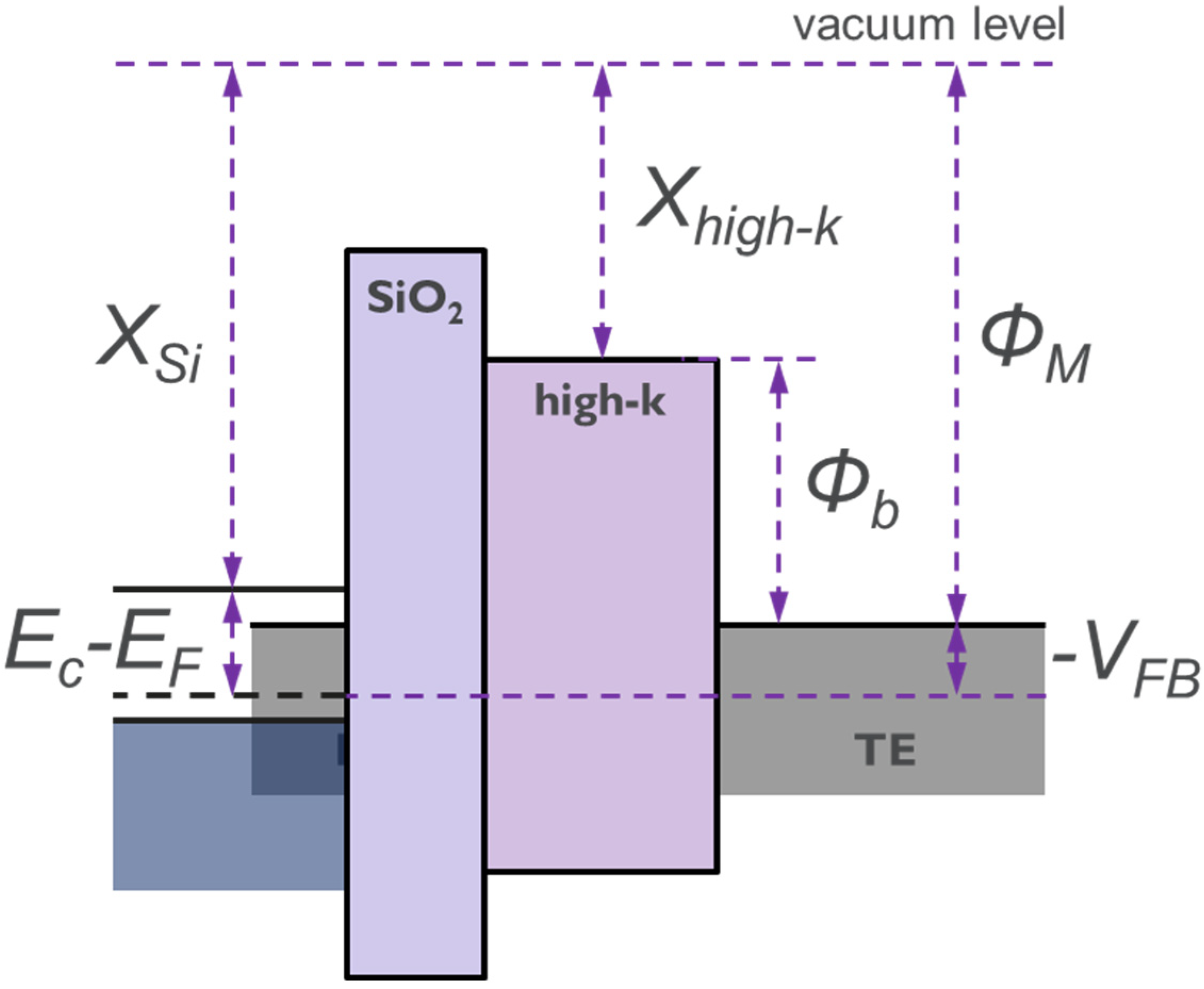
The WF of a metal on high-k is determined by extracting VFB from capacitance–voltage (CV) measurements on a metal-insulator-semiconductor (MIS) structure [22]. The schematic in Figure 2 shows the energy band diagram of an MIS structure. From this, we note that the metal work function can be expressed as follows
Φ M = V F B + χ S i + [ E C E F ] ,
where ΦM is metal work function, VFB is flat-band voltage computed from CV measurements, χSi is electron affinity of Si substrate, EC and EF are the conduction band minima and fermi level.
However, the charges present in the bulk and at the interfaces of the oxides [23] can affect the VFB as follows
Δ V F B = 0 t o x ρ ( z ) ( t o x z ) ε ( z ) ε 0 d z ,
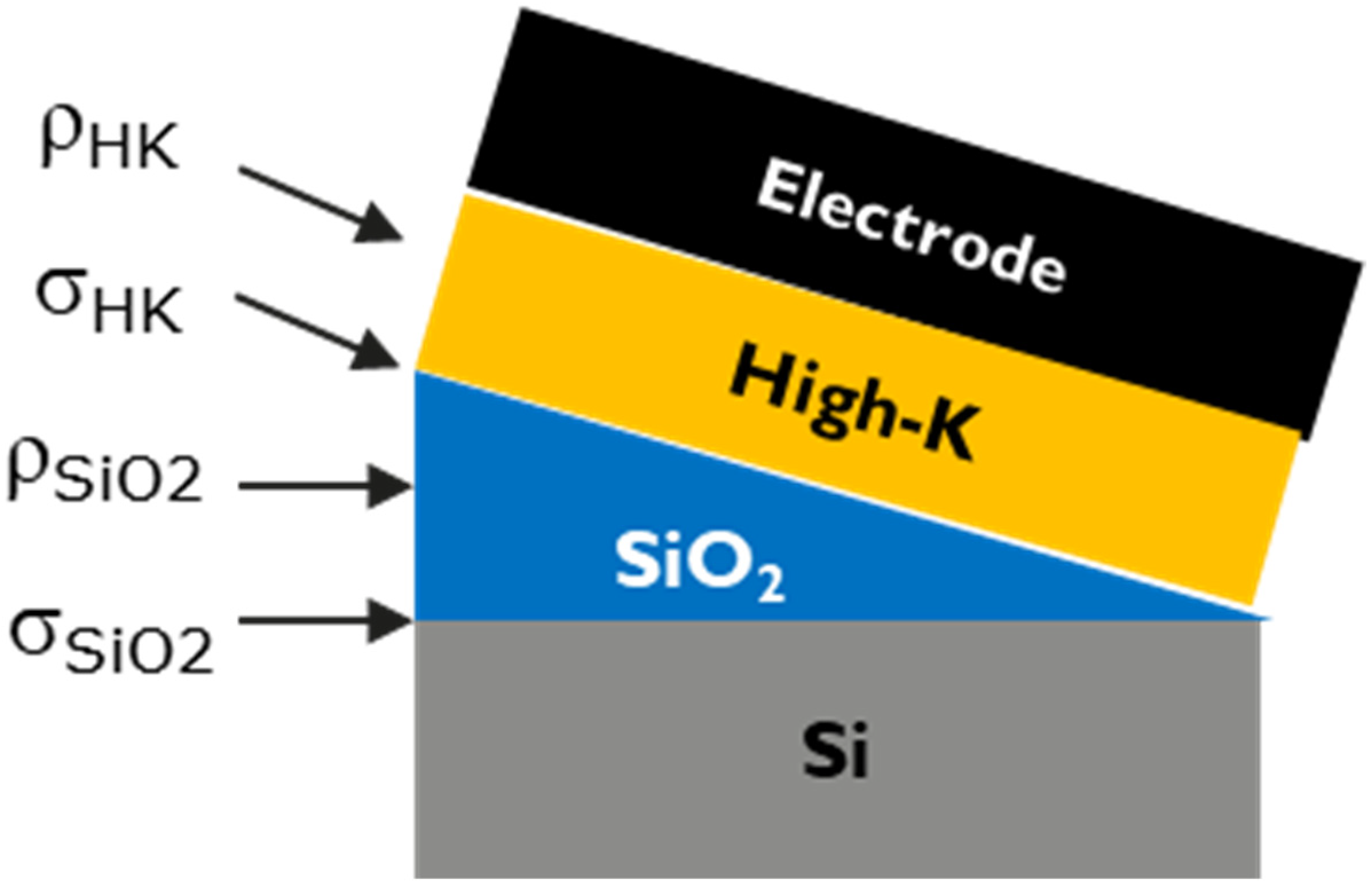
From the above equation, it is clear that the effect of these oxide charges can be cancelled out by extracting the VFB at zero oxide thickness. This calls for variations in SiO2 and high-k thicknesses. With the help of a slant etch technique, the thickness of SiO2 was varied across the wafer as shown in schematic in Figure 3. For each electrode, a set of 3 wafers with different high-k thicknesses (typically 3 nm, 5 nm, 7 nm) was used to provide enough variation and extract the WF conveniently. Typical CV measurements and VFB extraction procedure are discussed in Appendix A.
The impact of oxide charges on VFB can be mathematically expressed in terms of equivalent oxide thickness (EOT) and the corresponding charge densities as follows [24]
V F B = Φ M S + q · ρ H K · ε H K · E O T H K 2 2 · ε o x 2 · ε o + q · σ H K · E O T H K ε o x · ε o + q · ρ S i O 2 · 0.5 · T S i O 2 2 + ( ε H K ε o x ) · T S i O 2 · E O T H K ε o x · ε o + q · σ S i O 2 · E O T t o t a l ε o x · ε o ,
where q is the electron charge, ρHK and σHK are the bulk and interface charge densities of high-k dielectric, respectively. The terms ρSIO2 and σSIO2 are the corresponding bulk and interface charge densities of SiO2, respectively. EOTHK, TSiO2, and EOTtotal are the equivalent oxide thickness of high-k, thickness of SiO2, and both combined, respectively. The EOTtotal is in fact the measured EOT computed from the CV measurement of the MIS capacitors. The terms εHK, εox, εo are the relative permittivity of high-k, SiO2 and permittivity of free space, respectively. The ΦMS in the above equation, from which the metal WF is extracted, is later computed by extrapolating VFB at EOT (both high-k and SiO2) = 0.
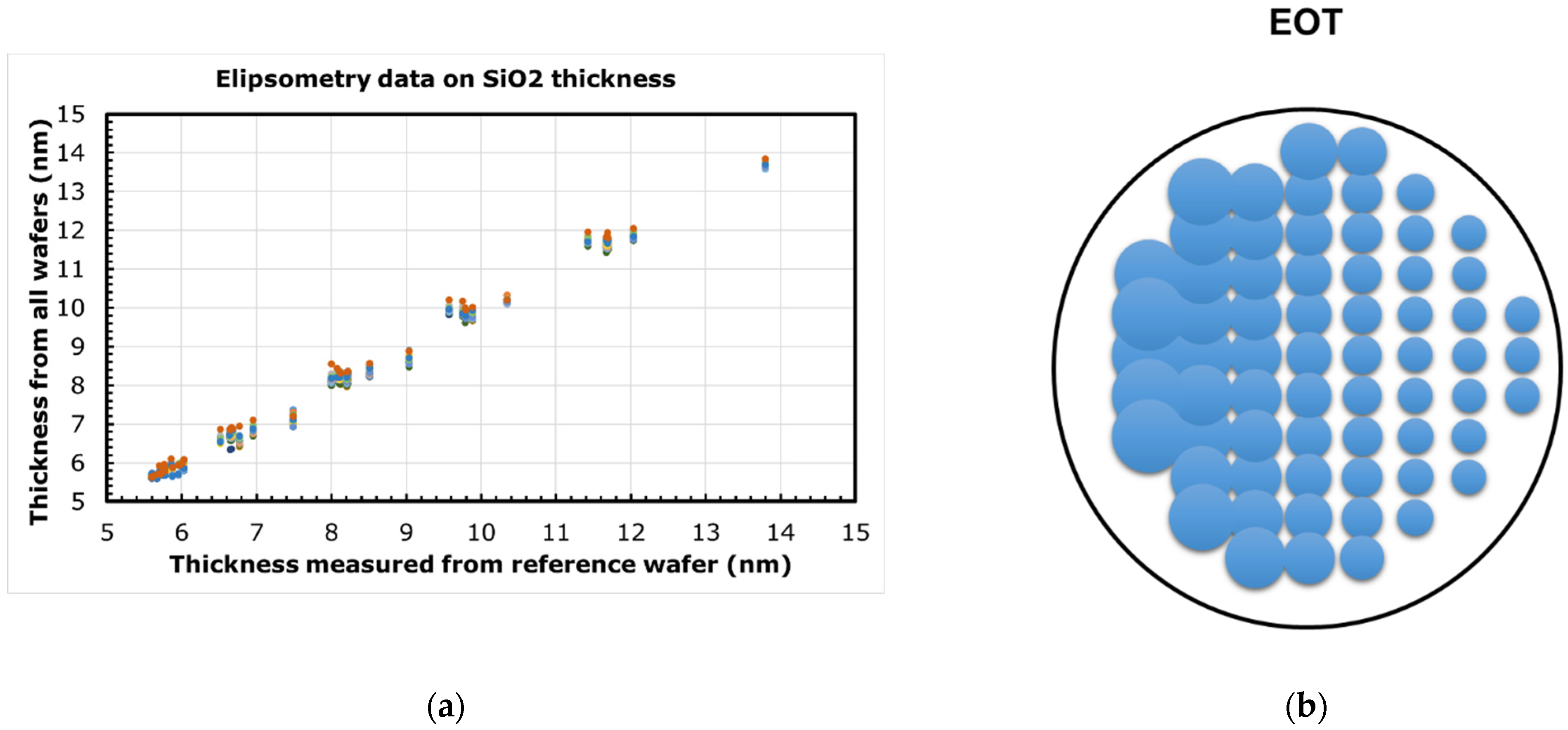
First, a 30 nm thick layer of high quality SiO2 was thermally grown at 900 °C. This was then etched back with a slant profile (as shown in Figure 3) by slowly immersing (at a constant rate) the wafer in a 1.9% hydrofluoric acid (HF) solution. The desired thickness range of SiO2 is obtained across the wafer by modifying the rate of immersion accordingly. A nominal thickness range of 3–12 nm was used in this work. Then, after the slant etch, a 3 nm plasma enhanced atomic layer deposition (PEALD) SiO2 was uniformly deposited at 300 °C, to mimic the blocking oxide in a 3D NAND device. Little wafer-to-wafer variations were observed in the oxide thickness, as measured by ellipsometry (see Figure 4a). The total EOT measured from CV will vary across the wafer due to the slant etch of thermal oxide, as shown in Figure 4b (bubble size represents magnitude of EOT).
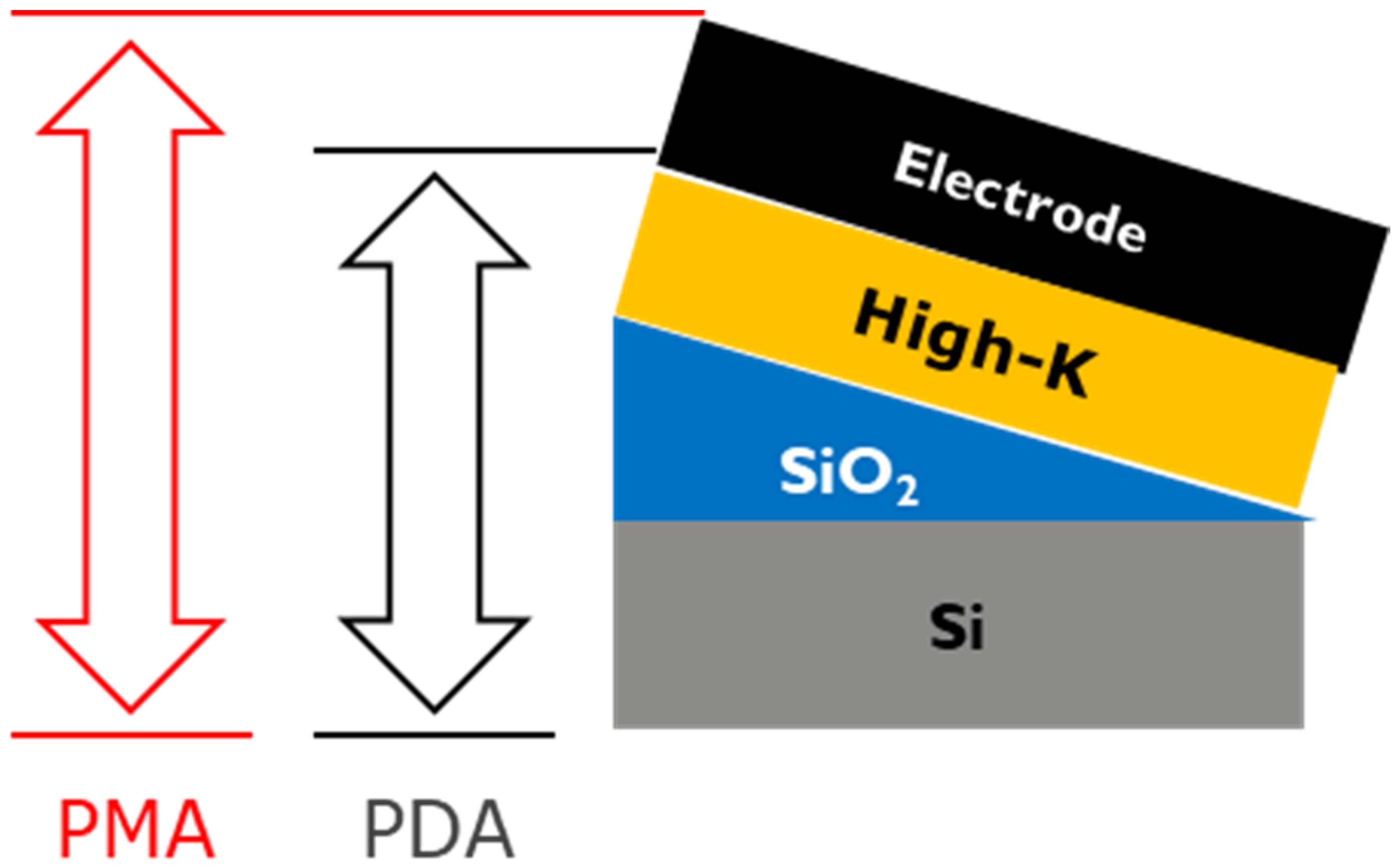
After this, high-k liners, such as Al2O3, ZrO2, and HfO2, were deposited at 300 °C to their desired thicknesses, using atomic layer deposition (ALD). Finally, 20 nm ALD Ru or ALD TiN or PVD Mo were then deposited as the gate electrode. In order to isolate the impact of thermal treatment on individual layers, a high temperature anneal (Tanneal) was performed at different stages of the stack formation (as shown in Figure 5). For instance, some of the capacitors were subjected to a post metallization anneal (PMA) for 20 min at 750 °C in N2 ambient. A few others were subjected to a post high-k deposition anneal (PDA), where the entire stack sans the metal electrode received a thermal treatment for 1 min at 1050 °C for Al2O3-based stacks and 1 min at 750 °C for the rest, all in N2 ambient. All wafers received a final sintering anneal in 5 atm H2 ambient at 450 °C for 30 min.
CV measurements were performed on 70 × 70 μm2 capacitors at a frequency of 100 kHz. The parameters needed for the WF extraction, namely, VFB, the substrate doping concentration and the total EOT, EOTtotal, are estimated (see Appendix A) with the help of NCSU’s CVC model fitting software [25]. Based on the expression for VFB from Equation (3), we can express VFB as a second order polynomial equation in terms of the EOT, as the one below
V F B = Φ M S + a · E O T H K 2 + b · E O T H K + p · T S i O 2 2 + q · T S i O 2 ,
where a, b, p, and q contain the charge densities of high-k and SiO2.
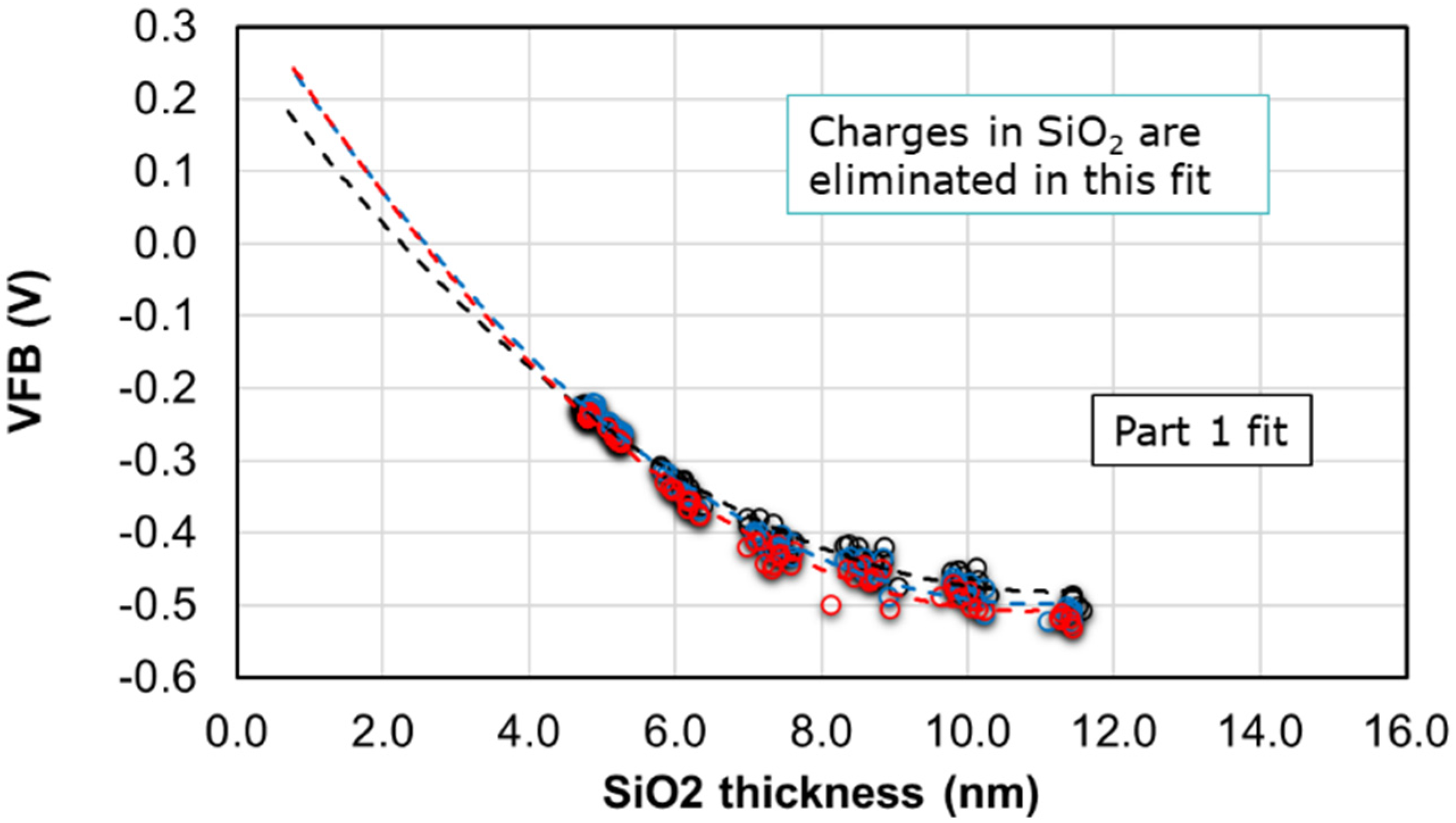
From the above equation, we can first eliminate the effect of charges in SiO2 with a second order polynomial fit of the VFB with the thickness of SiO2, TSiO2. A sample fit is shown in Figure 6. The intercept from the first fit contains the polynomial equation with high-k EOT, EOTHK and hence is used to eliminate the charges from high-k in a second fit.
As mentioned earlier, we have the EOTtotal of the stack as measured from CV. In order to get the TSiO2 to be used in the first fit, we make use of the ellipsometry data that was measured at preset locations across the wafer, after the slant etch and PEALD deposition. This data is then compared with corresponding dies for which the CV was measured. The difference between the measured EOTtotal and this ellipsometry data will give an estimate of the EOTHK.
The three curves shown in Figure 6 represent the three wafers with three different high-k thicknesses needed for sufficient variation to eliminate the charges affecting the VFB. The corresponding intercept from the 2nd order fit of the above curves is then used in a second fit, as shown in Figure 7 below.
The intercepts vs. the EOTHK will now help to eliminate the charges in high-k. The intercept from this second fit is the ΦMS from which the WF is computed using the formula
W F = 4.05 + Φ M S + E C E F ,
where E C E F ( i n   e V ) = 1.12 0.0257 ln ( 1.83 E 19 m e d i a n   d o p i n g   c o n c e n t r a t i o n   i n   t h e   s u b s t r a t e ) .

2.2. NAND Flash Erase Analysis

Incremental Step Pulse Erase (ISPE) characteristics were studied by monitoring the shift in VTH of MHONOS capacitors from their fresh state. The erase operation is divided into a number of steps with increasing amplitude (for a duration of 1 ms) in applied voltage and at the end of each of them a verify operation is applied to check the VTH. The amplitude and rate of change in VTH is considered as a measure of erase performance.
Large MHONOS capacitors (50 × 50 μm2) were fabricated on 300 mm p-doped Si (100) wafers, as shown in Figure 8b. N+-doped rings were processed, surrounding the active area of the capacitors, to provide minority carriers for program operation. In a study reported elsewhere [3], we have demonstrated a 3D NAND test structure with 5 layers and showed that the memory characteristics of the stack (see Figure 8a) are qualitatively similar to that of the planar test structures that we typically use (see Figure 8b). Moreover, the gate stack deposited in this work mimics the one of 3D NAND in production [3,26] in terms of annealing processes and high-k/metal gate depositions performed. Therefore, we could fairly say that the results obtained from the planar capacitors in this work are relevant for 3D NAND flash memory devices.
The MHONO stack, as seen from the TEM image in Figure 9a, consists of a 6 nm SiON (with 20% N-to-O ratio) tunnel layer deposited using CVD at 780 °C, 6 nm LPCVD Si3N4 charge trap layer deposited at 690 °C, 7 nm PEALD SiO2 blocking oxide deposited at 300 °C, and 2 nm ALD Al2O3 or ZrO2 or HfO2 high-k liner deposited at 300 °C. A total of 20 nm ALD Ru or ALD TiN or PVD Mo were then deposited as the gate electrode (WL, wordline). Similar to the study of WF extraction, a post metallization anneal, PMA for 20 min at 750 °C in N2 ambient, and a post deposition anneal, PDA for 2 min at 1050 °C for Al2O3 based stacks and 1 min at 750 °C for the rest, all in N2 ambient, were performed for some of the capacitors (see Figure 9b). All wafers were subject to a final sintering anneal either in forming gas at 420 °C for 20 min or in 5 atm H2 ambient at 450 °C for 30 min. We may note that the sintering anneal has little influence on the final erase saturation levels.

3. Results and Discussion

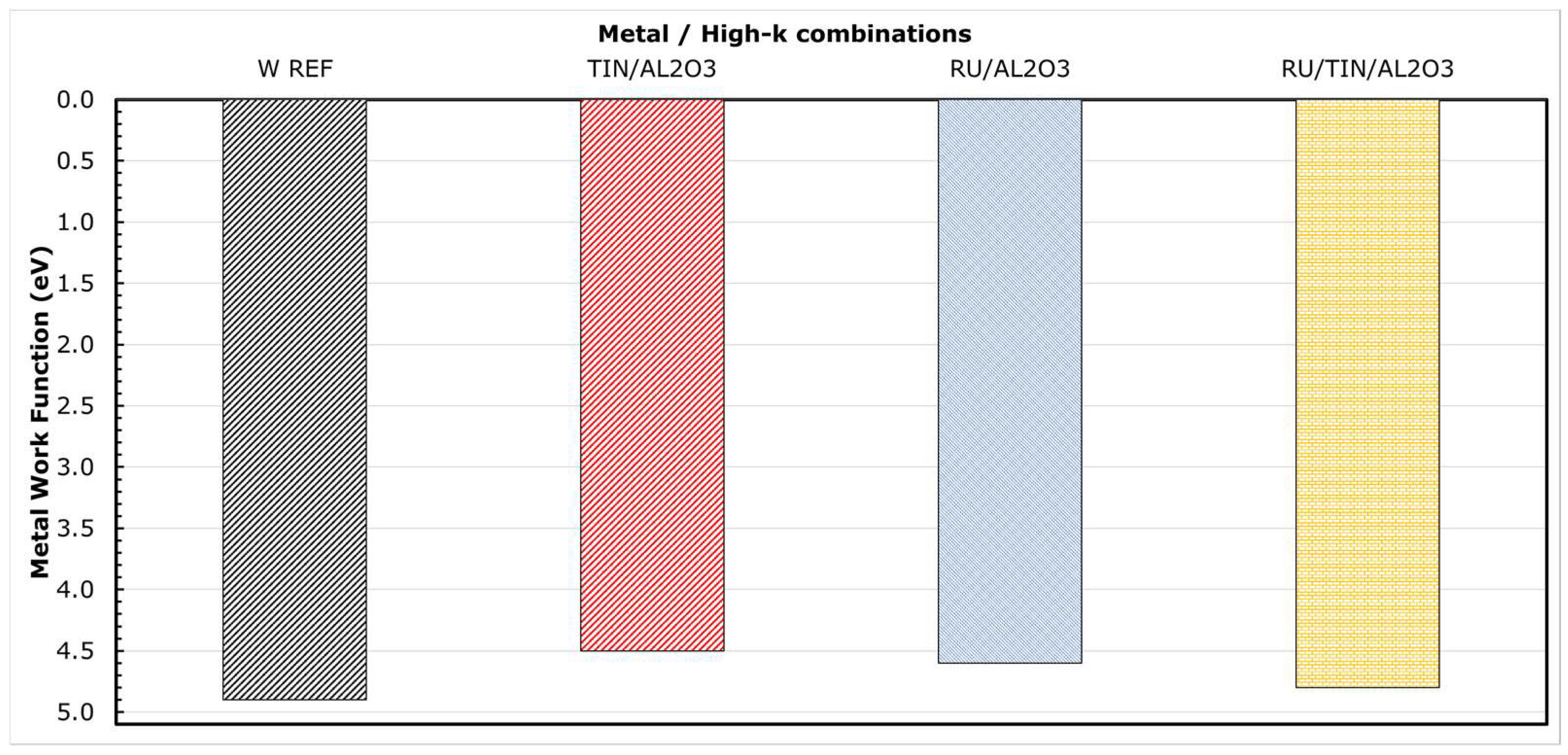
The metal WF extracted in this work are listed as a histogram plot in Figure 10 for a few metal/high-k combinations. No high temperature anneals were performed for these splits. W Ref represents the CVD W/thin (3 nm) ALD TiN/Al2O3 liner stack similar to the one used currently in 3D NAND production. We could note that the WF of TiN in combination with Al2O3 is estimated to be about 4.53 eV and is in close agreement with the actual TiN WF reported in the literature [27,28]. What is surprising is the WF of Ru in combination with Al2O3, which is about 200–300 meV less than those reported in the literature for Ru metal [29,30]. It has been demonstrated, using internal photoemission experiments [31], that subtle changes in the chemical bonding at the metal/high-k interface can cause a significant impact on the barrier height (Φb, as shown in Figure 2) at this interface. Such chemical modifications could occur from various processing, such as conditions of deposition, thermal budget, and ambient of annealing process. As a consequence, this could lead to a shift in the WF of the metal. However, it is possible to avert this interfacial reaction by using appropriate interfacial layer (IL), as can be seen from Figure 10. The WF of Ru improves to 4.8 eV by adding a thin (3 nm) TiN liner between Ru and Al2O3.
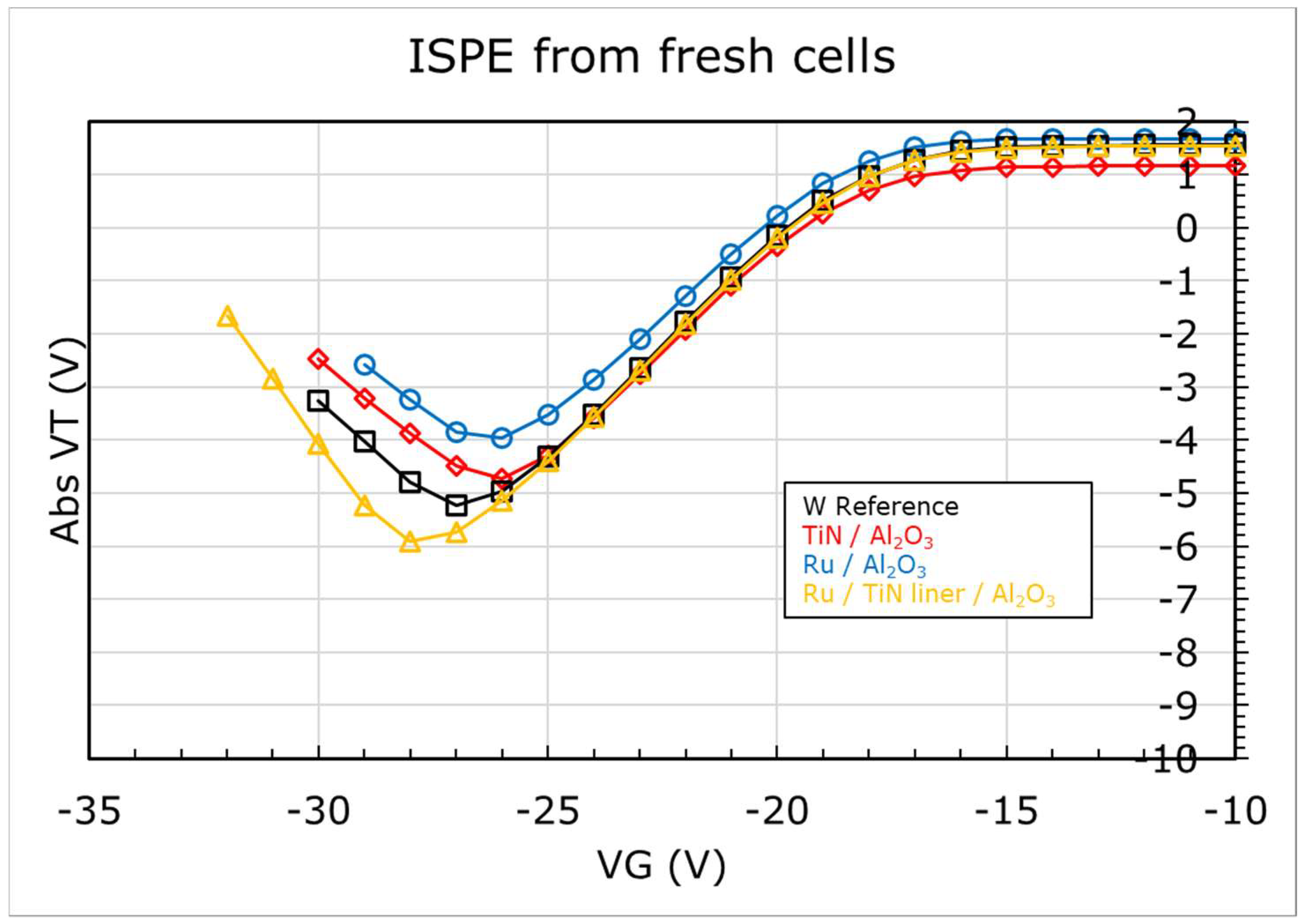
In order to verify whether these shifts, measured in WF of Ru, reflect the actual change in metal WF, we compared the erase performance of these stacks. Figure 11 shows the ISPE curves for MHONOS stacks containing the metal/high-k combinations from Figure 10. The erase saturation (lowest VT shift achieved in ISPE) for TiN and Ru on Al2O3 (WF ~4.6 eV) is comparable after accounting for the differences in the starting VTH, while that of W Ref (WF ~4.9 eV) is better, corroborating the WF difference between these stacks. With the addition of TiN liner, the WF of Ru improves, and so does the erase saturation.
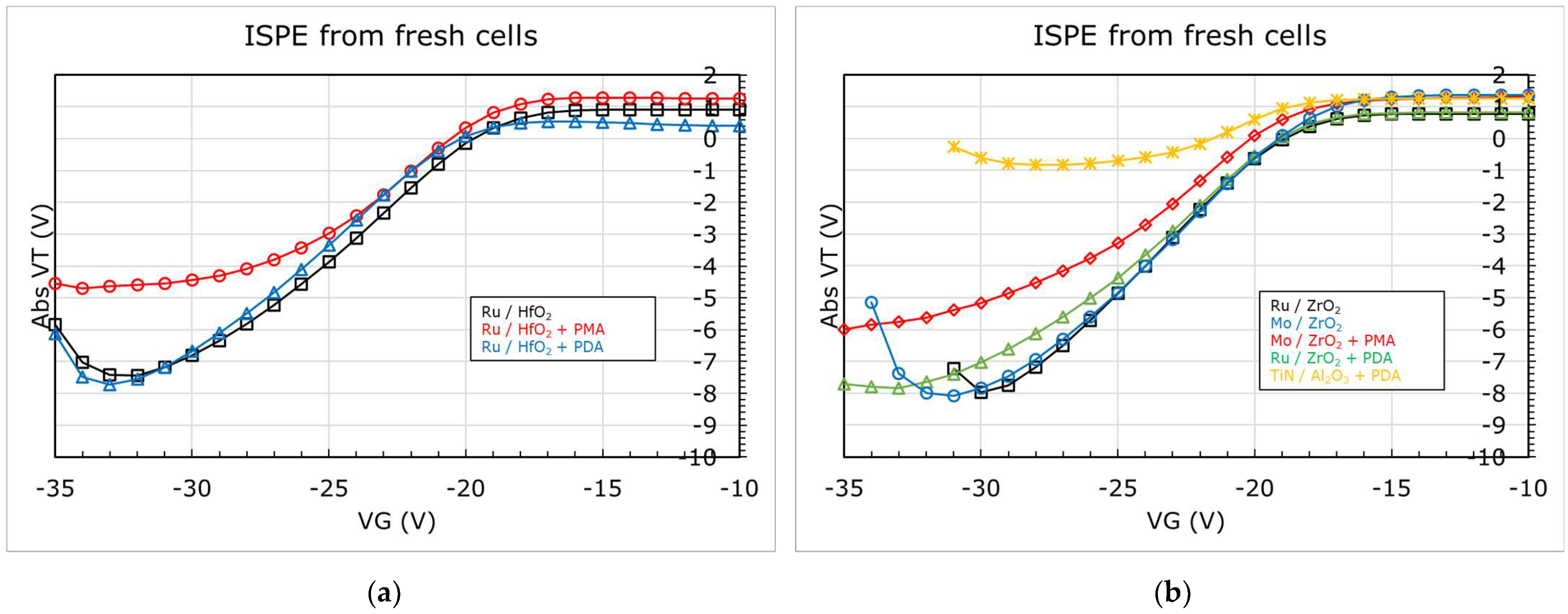
We may note that the WF extracted from the Ru/TiN/Al2O3 stack is slightly less than that of W Ref, i.e., W/TiN/Al2O3 stack, yet the erase is better with Ru. Before addressing this, let us look at Figure 12a,b, which display the WF extracted for Ru, Mo, and TiN in combination with HfO2, ZrO2, and Al2O3 after different annealing conditions, as described in Figure 5. From Figure 12a, we could note a significant reduction (>500 meV) in the WF of Ru after the thermal treatment, irrespective of whether the metal electrode received the anneal (PMA) or not (PDA). The ISPE curves for these stacks are shown in Figure 13a. The stack that received the PDA does not change in erase while the one that received a PMA degrades both in erase slope and saturation level. We can also note from Figure 12b and Figure 13b that without any high temperature anneals, both Ru and Mo show similar WF and erase saturation levels in combination with ZrO2. Though after a thermal treatment (PMA or PDA), the WF reduces irrespective of the metal or high-k used, the erase saturation depends on the type of anneal applied. These observations (made from Figure 10, Figure 12, Figure 13) hint that (a) the WF alone is not the reason for erase functionality, and (b) an extra factor, unaccounted in the extraction, is affecting the WF, resulting in an effective work function, eWF, being measured from the experiments.
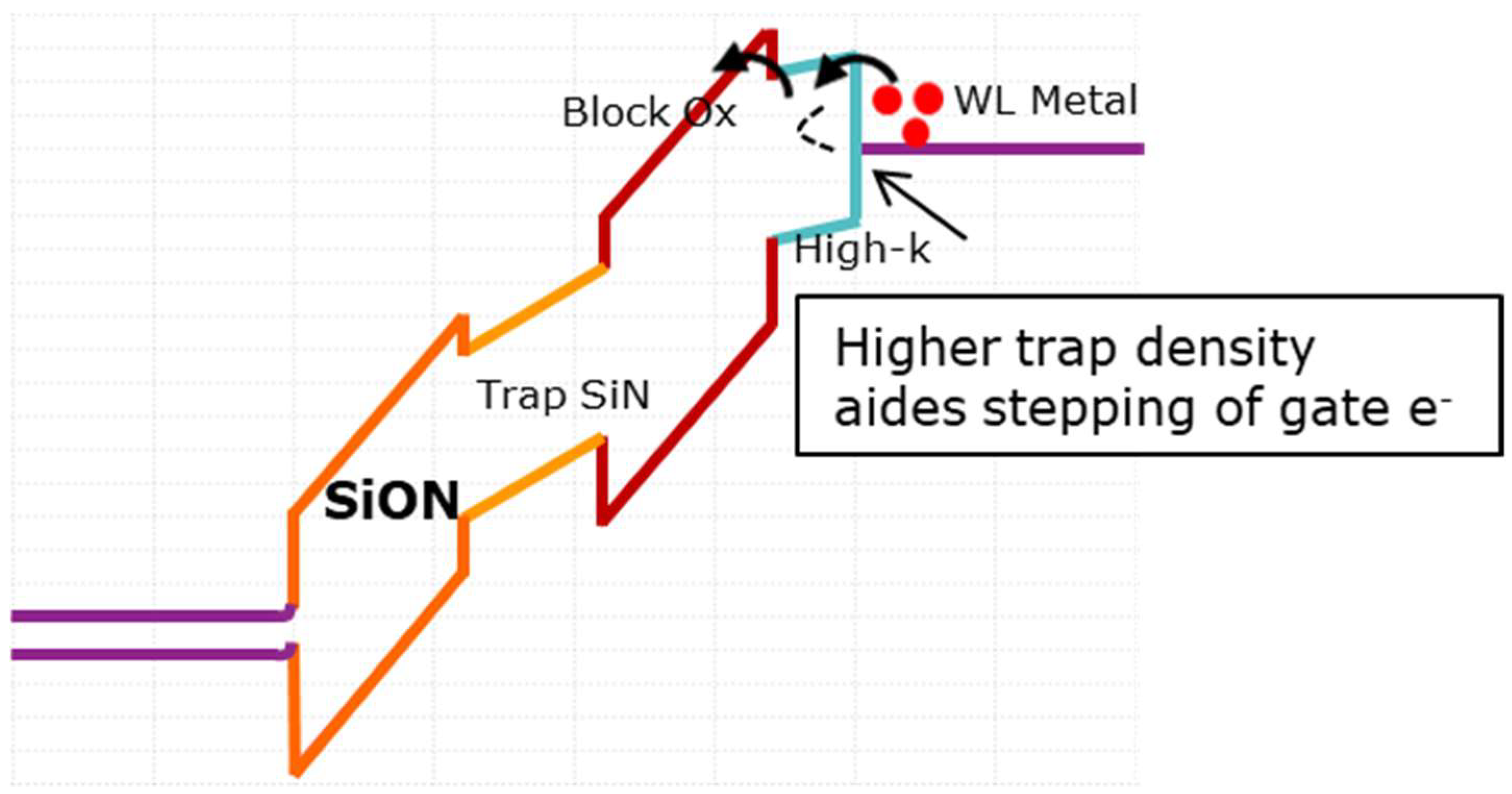
It is important to note that in the case of TiN with Al2O3 (PDA performed at 2min 1050 °C), the degradation in erase saturation is much worse, which is unlike the observations made for HfO2- and ZrO2-based stacks, and definitely not reflected in the WF reduction in TiN. A closer study on the high-k material properties reported elsewhere [32], investigated by trap spectroscopy, revealed that worse erase saturation levels at increased thermal budgets could be due to an increase in defect density in the high-k rather than a reduction in the metal WF itself. Higher defect density could increase trap-assisted tunneling [33], thereby increasing the leakage current during the erase operation (a typical band diagram during erase can be seen in Figure 14).
As discussed before, Fermi level pinning (FLP) at the metal/high-k interface, dipole formation at the high-k/SiO2 interface, and/or the energy offsets between the high-k and SiO2 have been suggested in the literature as possible root causes for an eWF. If the metal fermi level is pinned, then the Φb at the interface should be different, which reflects in the erase saturation levels. Based on the observations made from Figure 11 for Ru with TiN liner and Figure 13 for Ru stacks after PDA, this effect can be ruled out. A common opinion in the literature [21,34,35,36] is that a dipole formed at the high-k/SiO2 interface is the dominant factor causing appreciable shifts in VFB, and hence, the WF extracted from it. Many physical models exist to explain this dipole formation, attributing it to dielectric contact induced gap states [37] or dictated by the electronegativity and ionic radii of the cations (from the high-k) [38], However, the most acceptable explanation seems to be oxygen vacancies driven by structural stabilization at the high-k/SiO2 interface [18,19,20,21,34,39,40]. Moreover, the dipole formation at the high-k/SiO2 interface should not affect the erase performance of flash memory, which is determined by the electron injection dynamics at the gate contact.
To further clarify the impact of dipole formation on erase performance of flash memory, dipole-forming interlayers (DIL) [36,41,42], namely, Al2O3 and La2O3 (0.6 nm each), were studied as part of the MHONOS stack (shown in Figure 15). The DIL were deposited between metal and high-k or high-k and SiO2, with TiN/HfO2 being used as the control gate electrode and high-k dielectric. All the stacks received a PDA for 1.5 s at 1050 °C in N2 ambient. The corresponding shifts in VFB caused by the interlayers were extracted from CV measurements using CVC fitting (as can be seen in Figure 16).
We could note from Figure 16a that with the addition of Al2O3 DIL between HfO2 and SiO2, the VFB positively increases by about 120 meV, while it remains unchanged when Al2O3 is inserted between the metal and high-k. Though much higher VFB shifts are theoretically reported for Al2O3 [18], the processing conditions and thickness of the DIL play a major role in determining the magnitude of the VFB shifts [21,42,43]. Furthermore, if we add 0.6 nm La2O3 DIL between HfO2 and SiO2 while keeping the Al2O3 between TiN and HfO2, we notice a negative drop of about 140 meV in the VFB, which is in line with trends reported in the literature [44,45]. It is worth to note that the trend in VFB remains unchanged after a PMA for 20 min at 750 °C in N2 ambient (see Figure 16b).
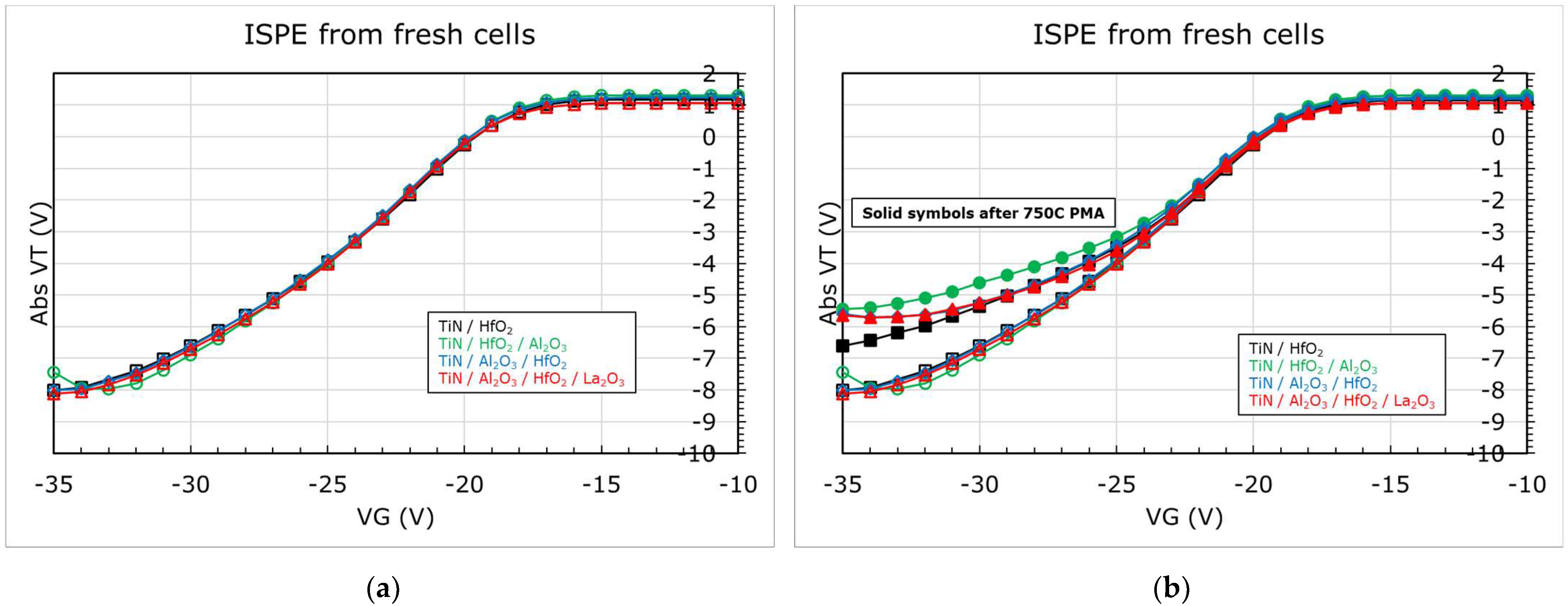
The ISPE curves for these stacks without PMA are shown in Figure 17a. We could note, despite the differences in VFB, that there is no difference in the erase performance of these stacks. On the contrary, when the stacks were subjected to PMA, the erase depends on the material present in the stack, as can be seen in Figure 17b. The control sample with only TiN and HfO2 shows slight degradation after PMA. However, the stacks with DIL show higher reduction in erase, even worse when the Al2O3 is present next to the blocking oxide, though it shows a positive VFB shift (indicating a higher eWF). It is well known that Al2O3 dielectric suffers from a wider band of defect profile [46]. Recalling the discussion from before on the possible impact of defect density in the high-k on erase (see Figure 14), we could fairly say that the above results corroborate this hypothesis.

4. Conclusions

We have extracted and studied the shifts in metal work function (i.e., effective work function, eWF), in response to different processing parameters, such as gate electrode and high-k dielectric materials, and variations in annealing conditions. By studying the work function in combination with the erase performance of NAND flash memory, we were able to narrow down the origin of eWF to dipole formation due to (a) interfacial reactions at the metal/high-k interface and/or (b) possible oxygen vacancies driven by structural stabilization at the high-k/SiO2 interface. It must be noted that based on the above studies, we did not observe fermi level pinning at the metal/high-k interface.
We also verified and validated the negligible impact of dipole on erase performance by studying different dipole forming interlayers in the memory cell. It is clear that the metal WF extraction is convoluted by dipole formation, while the erase performance of a flash memory cell is affected more by the trap profile in the high-k liner than any other factors that cause shift in flat band voltage.

Author Contributions

S.R. was involved in the conceptualization, investigation, formal analysis, visualization, and data curation. The author was also involved in writing the original draft of this manuscript. A.A. was involved in the conceptualization and investigation. L.-Å.R. was involved in the conceptualization, supervision, and validation. L.B. was involved in the conceptualization, investigation, validation, and writing—review and editing. The author was also involved in formal analysis and visualization in the early stages of this work. G.K.E.H. was involved in the conceptualization and investigation in the early stages of this work. B.K. and A.B. were involved in the methodology and software development required for the formal analysis in this work. L.N. and J.-P.S. were involved in the investigation and developing material resources for this work. G.V.d.b. and M.R. were involved in conceptualization, project administration, supervision, and writing—review and editing. All authors have read and agreed to the published version of the manuscript.

Funding

This work is supported by IMEC’s Industrial Affiliation Program on Storage Memory devices.

Data Availability Statement

Not applicable.

Acknowledgments

Authors acknowledge IMEC’s pilot line, the various engineering, process, and support teams. Authors also acknowledge HPSP Inc. for the high-pressure annealing experiment.

Conflicts of Interest

The authors declare no conflict of interest.

Appendix A

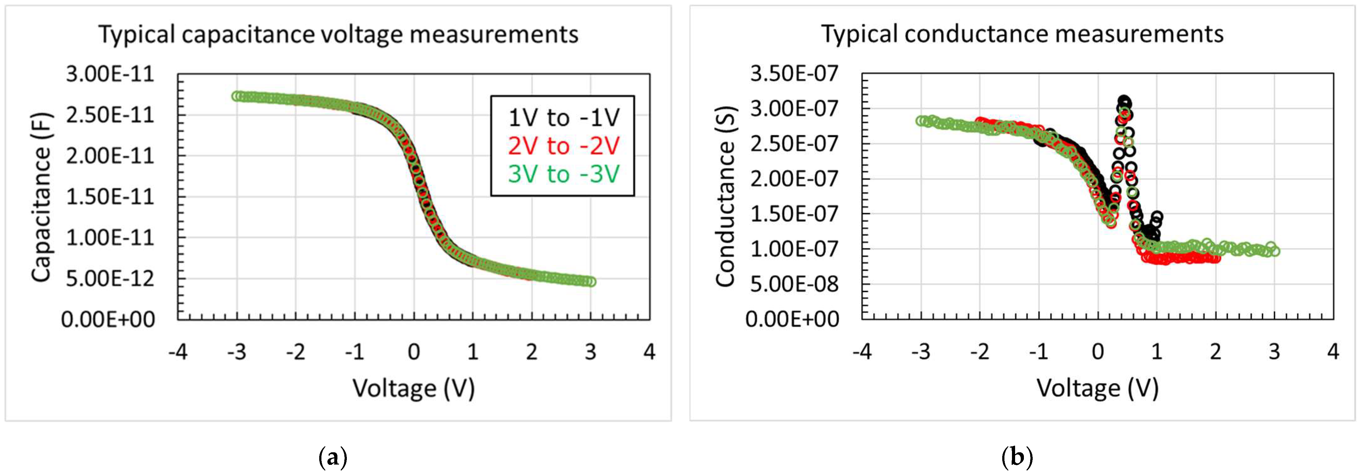
Figure A1 shows the typical capacitance and conductance curves obtained on 70 × 70 μm2 capacitors at a frequency of 100 kHz. The capacitors were fabricated on a p-doped, 300 mm Si substrate with SiO2 bevel. Data is shown for 3 nm HfO2 high-k liner and Ru gate electrode. The capacitors are sequentially measured at different voltage sweep ranges (i) 1 V to −1 V, (ii) 2 V to −2 V, (iii) 3 V to −3 V. We could notice that there is little impact of the voltage sweep on the hysteresis of the curves. Capacitance data from the 2 V to −2 V voltage sweep range is then used to subsequently extract the flat band voltage, VFB.
Figure A1. Typical (a) capacitance and (b) conductance measurements performed in this work. Data shown for Ru/HfO2 combination on a SiO2 bevel (slant etch) on a p-type Si substrate. The capacitors are sequentially measured at different voltage sweep ranges (i) 1 V to −1 V, (ii) 2 V to −2 V, (iii) 3 V to −3 V.
Micromachines 12 01084 g0a1
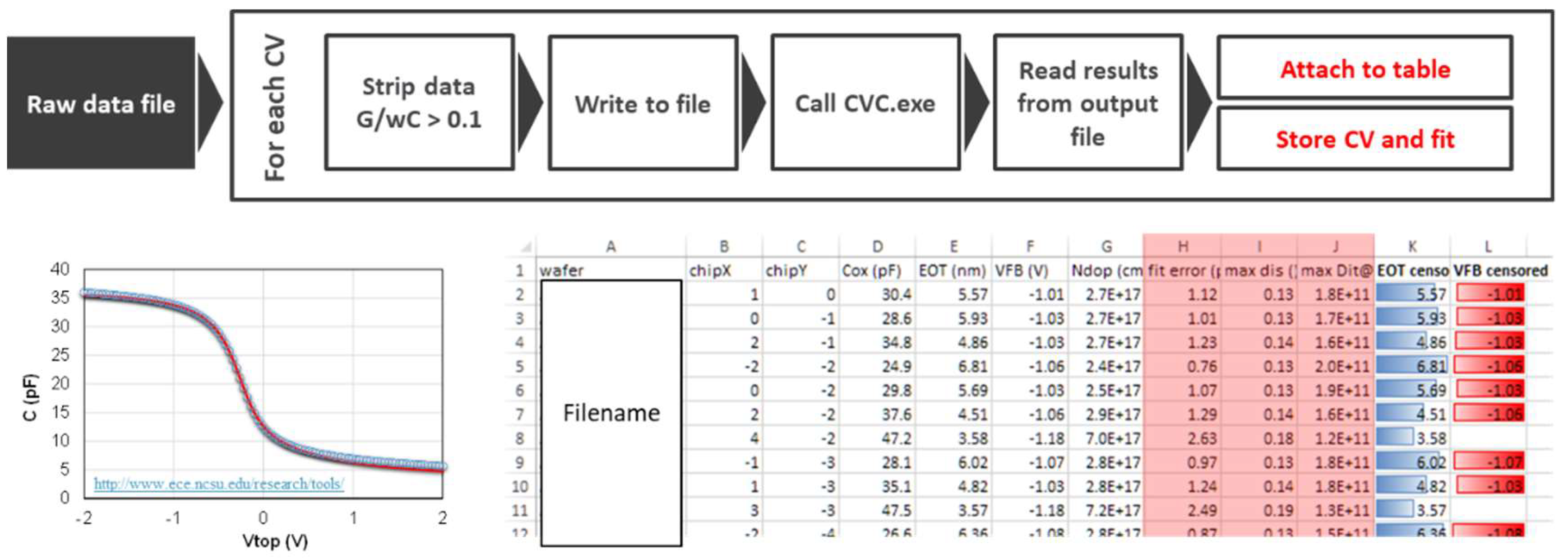
Figure A2 shows the schematic of an automated VFB extraction with a robust and traceable procedure. Test for gate leakage is performed in the measurement routine (not shown) and warnings are issued if any issues are encountered. Only those data with appropriate fit errors are filtered for further analysis. The rest of the analysis follows as discussed in the main article (see page 5 onwards).
Figure A2. Example procedure of data extraction from measurement.
Micromachines 12 01084 g0a2

References

  1. Parat, K.; Goda, A. Scaling Trends in NAND Flash. In Proceedings of the IEEE International Electron Devices Meeting (IEDM), San Francisco, CA, USA, 1–5 December 2018; pp. 2.1.1–2.1.4. [Google Scholar] [CrossRef]
  2. Tanaka, H.; Kido, M.; Yahashi, K.; Oomura, M.; Katsumata, R.; Kito, M.; Fukuzumi, Y.; Sato, M.; Nagata, Y.; Matsuoka, Y.; et al. Bit Cost Scalable Technology with Punch and Plug Process for Ultra High Density Flash Memory. In Proceedings of the IEEE Symposium on VLSI Technology, Kyoto, Japan, 12–14 June 2007; pp. 14–15. [Google Scholar] [CrossRef]
  3. Breuil, L.; El Hajjam, G.K.; Ramesh, S.; Ajaykumar, A.; Arreghini, A.; Zhang, L.; Sebaai, F.; Nyns, L.; Raymaekers, T.; Rosmeulen, M.; et al. Integration of Ruthenium-based Wordline in a 3-D NAND Memory Devices. In Proceedings of the IEEE International Memory Workshop (IMW), Dresden, Germany, 17–20 May 2020; pp. 1–4. [Google Scholar] [CrossRef]
  4. Jeon, S.; Han, J.; Lee, J.; Choi, S.; Hwang, H.; Kim, C. High Work-Function Metal Gate and High-kappaDielectrics for Charge Trap Flash Memory Device Applications. IEEE Trans. Electron Devices 2005, 52, 2654–2659. [Google Scholar] [CrossRef]
  5. Tan, C.-L.; Lavizzari, S.; Blomme, P.; Breuil, L.; Vecchio, G.; Sebaai, F.; Paraschiv, V.; Tao, Z.; Schepers, B.; Nyns, L.; et al. In Depth Analysis of 3D NAND Enablers in Gate Stack Integration and Demonstration in 3D Devices. In Proceedings of the IEEE International Memory Workshop (IMW), Monterey, CA, USA, 14–17 May 2017; pp. 1–4. [Google Scholar] [CrossRef]
  6. Arreghini, A.; Van den Bosch, G.; Kar, G.S.; Van Houdt, J. Ultimate Scaling Projection of Cylindrical 3D SONOS Devices. In Proceedings of the 2012 4th IEEE International Memory Workshop, Milan, Italy, 20–23 May 2012; pp. 1–4. [Google Scholar] [CrossRef]
  7. Charbonnier, M.; Mitard, J.; Leroux, C.; Ghibaudo, G.; Cosnier, V.; Besson, P.; Martin, F.; Reimbold, G. Reliable extraction of metal gate work function by combining two electrical characterization methods. In Proceedings of the ESSDERC 2007—37th European Solid State Device Research Conference, Munich, Germany, 11–13 September 2007; pp. 275–278. [Google Scholar] [CrossRef]
  8. O’Sullivan, B.; Kaushik, V.; Ragnarsson, L.-A.; Onsia, B.; Van Hoornick, N.; Rohr, E.; DeGendt, S.; Heyns, M. Device performance of transistors with high-/spl kappa/ dielectrics using cross-wafer-scaled interface-layer thickness. IEEE Electron Device Lett. 2006, 27, 546–548. [Google Scholar] [CrossRef]
  9. Akiyama, K.; Wang, W.; Mizubayashi, W.; Ikeda, M.; Ota, H.; Nabatame, T.; Toriumi, A. Roles of oxygen vacancy in HfO2/ultra-thin SiO2 gate stacks—Comprehensive understanding of VFB roll-off -. In Proceedings of the 2008 Symposium on VLSI Technology, Honolulu, HI, USA, 17–19 June 2008; pp. 80–81. [Google Scholar] [CrossRef]
  10. Kadoshima, M.; Ogawa, A.; Ota, H.; Ikeda, M.; Takahashi, M.; Satake, H.; Nabatame, T.; Toriumi, A. Two Different Mechanisms for Determining Effective Work Function (fm,eff) on High-k—Physical Understanding and Wider Tunability of fm,eff. In Digest of Technical Papers, Proceedings of the 2006 Symposium on VLSI Technology, Honolulu, HI, USA, 13–15 June 2006; IEEE: Piscataway, NJ, USA, 2006; pp. 180–181. [Google Scholar] [CrossRef]
  11. Kamimuta, Y.; Iwamoto, K.; Nunoshige, Y.; Hirano, A.; Mizubayashi, W.; Watanabe, Y.; Migita, S.; Ogawa, A.; Ota, H.; Nabatame, T.; et al. Comprehensive Study of VFB Shift in High-k CMOS—Dipole Formation, Fermi-level Pinning and Oxygen Vacancy Effect. In Proceedings of the IEEE International Electron Devices Meeting, Washington, DC, USA, 10–12 December 2007; pp. 341–344. [Google Scholar] [CrossRef]
  12. Kornblum, L.; Rothschild, J.A.; Kauffmann, Y.; Brener, R.; Eizenberg, M. Band offsets and Fermi level pinning at metal-Al2O3 interfaces. Phys. Rev. B 2011, 84, 15. [Google Scholar] [CrossRef]
  13. Mönch, W. Metal-semiconductor contacts: Electronic properties. Surf. Sci. 1994, 299–300, 928–944. [Google Scholar] [CrossRef]
  14. Yeo, Y.-C.; King, T.-J.; Hu, C. Metal-dielectric band alignment and its implications for metal gate complementary metal-oxide-semiconductor technology. J. Appl. Phys. 2002, 92, 7266–7271. [Google Scholar] [CrossRef] [Green Version]
  15. Wen, H.-C.; Majhi, P.; Choi, K.; Park, C.; Alshareef, H.N.; Harris, H.R.; Luan, H.; Niimi, H.; Park, H.-B.; Bersuker, G.; et al. Decoupling the Fermi-level pinning effect and intrinsic limitations on p-type effective work function metal electrodes. Microelectron. Eng. 2008, 85, 2–8. [Google Scholar] [CrossRef]
  16. Akasaka, Y.; Nakamura, G.; Shiraishi, K.; Umezawa, N.; Yamabe, K.; Ogawa, O.; Lee, M.; Amiaka, T.; Kasuya, T.; Watanabe, H.; et al. Modified Oxygen Vacancy Induced Fermi Level Pinning Model Extendable to P-Metal Pinning. Jpn. J. Appl. Phys. 2006, 45, L1289–L1292. [Google Scholar] [CrossRef]
  17. Yang, Z.C.; Huang, A.P.; Zheng, X.H.; Xiao, Z.S.; Liu, X.Y.; Zhang, X.W.; Chu, P.K.; Wang, W.W. Fermi-Level Pinning at Metal/High-k Interface Influenced by Electron State Density of Metal Gate. IEEE Electron Device Lett. 2010, 31, 1101–1103. [Google Scholar] [CrossRef]
  18. Kita, K.; Toriumi, A. Origin of electric dipoles formed at high-k/SiO2 interface. Appl. Phys. Lett. 2009, 94, 132902. [Google Scholar] [CrossRef]
  19. Bersuker, G.; Park, C.S.; Wen, H.-C.; Choi, K.; Price, J.; Lysaght, P.; Tseng, H.-H.; Sharia, O.; Demkov, A.; Ryan, J.T.; et al. Origin of the Flatband-Voltage Roll-Off Phenomenon in Metal/High- k Gate Stacks. IEEE Trans. Electron Devices 2010, 57, 2047–2056. [Google Scholar] [CrossRef]
  20. Iwamoto, K.; Ogawa, A.; Kamimuta, Y.; Watanabe, Y.; Mizubayashi, W.; Migita, S.; Morita, Y.; Takahashi, M.; Ito, H.; Ota, H.; et al. Re-examination of Flat-Band Voltage Shift for High-k MOS Devices. In Proceedings of the 2007 IEEE Symposium on VLSI Technology, Kyoto, Japan, 12–14 June 2007; pp. 70–71. [Google Scholar] [CrossRef]
  21. Charbonnier, M.; Leroux, C.; Cosnier, V.; Besson, P.; Martinez, E.; Benedetto, N.; Licitra, C.; Rochat, N.; Gaumer, C.; Kaja, K.; et al. Measurement of Dipoles/Roll-Off /Work Functions by Coupling CV and IPE and Study of Their Dependence on Fabrication Process. IEEE Trans. Electron Devices 2010, 57, 1809–1819. [Google Scholar] [CrossRef]
  22. Padovani, A.; Kaczer, B.; Pesic, M.; Belmonte, A.; Popovici, M.; Nyns, L.; Linten, D.; Afanas’Ev, V.V.; Shlyakhov, I.; Lee, Y.; et al. A Sensitivity Map-Based Approach to Profile Defects in MIM Capacitors From I-V, C-V, and G-V Measurements. IEEE Trans. Electron Devices 2019, 66, 1892–1898. [Google Scholar] [CrossRef]
  23. Kaushik, V.; O’Sullivan, B.; Pourtois, G.; Van Hoornick, N.; Delabie, A.; Van Elshocht, S.; Deweerd, W.; Schram, T.; Pantisano, L.; Rohr, E.; et al. Estimation of fixed charge densities in hafnium-silicate gate dielectrics. IEEE Trans. Electron Devices 2006, 53, 2627–2633. [Google Scholar] [CrossRef]
  24. Jha, R.; Gurganos, J.; Kim, Y.; Choi, R.; Lee, J.; Misra, V. A Capacitance-Based Methodology for Work Function Extraction of Metals on High-kappa. IEEE Electron Device Lett. 2004, 25, 420–423. [Google Scholar] [CrossRef]
  25. Hauser, J.R. North Carolina State Umiversity’s CVC. Computer Analysis Software, 1999. [Google Scholar]
  26. Park, J.-Y.; Yun, D.-H.; Kim, S.-Y.; Choi, Y.-K. Suppression of Self-Heating Effects in 3-D V-NAND Flash Memory Using a Plugged Pillar-Shaped Heat Sink. IEEE Electron Device Lett. 2019, 40, 212–215. [Google Scholar] [CrossRef]
  27. Calzolari, A.; Catellani, A. Controlling the TiN Electrode Work Function at the Atomistic Level: A First Principles Investigation. IEEE Access 2020, 8, 156308–156313. [Google Scholar] [CrossRef]
  28. Wen, H.-C.; Choi, R.; Brown, G.; BosckeBoscke, T.; Matthews, K.; Harris, H.; Choi, K.; Alshareef, H.N.; Luan, H.; Bersuker, G.; et al. Comparison of effective work function extraction methods using capacitance and current measurement techniques. IEEE Electron Device Lett. 2006, 27, 598–601. [Google Scholar] [CrossRef]
  29. Park, K.J.; Doub, J.M.; Gougousi, T.; Parsons, G. Microcontact patterning of ruthenium gate electrodes by selective area atomic layer deposition. Appl. Phys. Lett. 2005, 86, 051903. [Google Scholar] [CrossRef]
  30. Pantisano, L.; Schram, T.; Li, Z.; Lisoni, J.G.; Pourtois, G.; De Gendt, S.; Brunco, D.P.; Akheyar, A.; Afanas’Ev, V.V.; Shamuilia, S.; et al. Ruthenium gate electrodes on SiO2 and HfO2: Sensitivity to hydrogen and oxygen ambients. Appl. Phys. Lett. 2006, 88, 243514. [Google Scholar] [CrossRef]
  31. Afanas’Ev, V.V.; Stesmans, A. Internal photoemission at interfaces of high-κ insulators with semiconductors and metals. J. Appl. Phys. 2007, 102, 81301. [Google Scholar] [CrossRef]
  32. Ramesh, S.; Ajaykumar, A.; Bastos, J.; Breuil, L.; Arreghini, A.; Nyns, L.; Soulié, J.-P.; Ragnarsson, L.-Å.; Schleicher, F.; Jossart, N.; et al. Erase Behavior of Charge Trap Flash Memory Devices using High-k Dielectric as Blocking Oxide Liner. In Proceedings of the IEEE Semiconductor Interface Specialists Conference, San Diego, CA, USA, 6–8 December 2020. [Google Scholar]
  33. Chou, A.I.; Lai, K.; Kumar, K.; Chowdhury, P.; Lee, J.C. Modeling of stress-induced leakage current in ultrathin oxides with the trap-assisted tunneling mechanism. Appl. Phys. Lett. 1997, 70, 3407–3409. [Google Scholar] [CrossRef]
  34. Iwamoto, K.; Kamimuta, Y.; Ogawa, A.; Watanabe, Y.; Migita, S.; Mizubayashi, W.; Morita, Y.; Takahashi, M.; Ota, H.; Nabatame, T.; et al. Experimental evidence for the flatband voltage shift of high-k metal-oxide-semiconductor devices due to the dipole formation at the high-k∕SiO2 interface. Appl. Phys. Lett. 2008, 92, 132907. [Google Scholar] [CrossRef]
  35. Suarez-Segovia, C.; Caubet, P.; Joseph, V.; Gourhant, O.; Romano, G.; Domengie, F.; Ghibaudo, G. Effective Work Function Shift Induced by TiN Sacrificial Metal Gates as a Function of Their Thickness and Composition in 14 nm NMOS devices. In Proceedings of the International Conference on Solid State Devices and Materials, Ibaraki, Japan, 8–11 September 2014. [Google Scholar] [CrossRef] [Green Version]
  36. Bersch, E.; Di, M.; Consiglio, S.; Clark, R.D.; Leusink, G.J.; Diebold, A.C. Complete band offset characterization of the HfO2/SiO2/Si stack using charge corrected x-ray photoelectron spectroscopy. J. Appl. Phys. 2010, 107, 043702. [Google Scholar] [CrossRef]
  37. Wang, X.; Han, K.; Wang, W.; Chen, S.; Ma, X.; Chen, D.; Zhang, J.; Du, J.; Xiong, Y.; Huang, A. Physical origin of dipole formation at high-k/SiO2 interface in metal-oxide-semiconductor device with high-k/metal gate structure. Appl. Phys. Lett. 2010, 96, 152907. [Google Scholar] [CrossRef]
  38. Sivasubramani, P.; Boscke, T.S.; Huang, J.; Young, C.D.; Kirsch, P.D.; Krishnan, S.A.; Quevedo-Lopez, M.A.; Govindarajan, S.; Ju, B.S.; Harris, H.R.; et al. Dipole Moment Model Explaining nFET Vt Tuning Utilizing La, Sc, Er, and Sr Doped HfSiON Dielectrics. In Proceedings of the 2007 IEEE Symposium on VLSI Technology, Kyoto, Japan, 12–14 June 2007; pp. 68–69. [Google Scholar] [CrossRef]
  39. Zheng, X.H.; Huang, A.P.; Xiao, Z.S.; Yang, Z.C.; Wang, M.; Zhang, X.W.; Wang, W.W.; Chu, P.K. Origin of flat-band voltage sharp roll-off in metal gate/high-k/ultrathin- SiO2/Si p-channel metal-oxide-semiconductor stacks. Appl. Phys. Lett. 2010, 97, 132908. [Google Scholar] [CrossRef]
  40. Sharia, O.; Demkov, A.A.; Bersuker, G.; Lee, B.H. Theoretical study of the insulator/insulator interface: Band alignment at theSiO2∕HfO2junction. Phys. Rev. B 2007, 75, 035306. [Google Scholar] [CrossRef]
  41. Franco, J.; Wu, Z.; Rzepa, G.; Vandooren, A.; Arimura, H.; Claes, D.; Horiguchi, N.; Collaert, N.; Linten, D.; Grasser, T.; et al. Low Thermal Budget Dual-Dipole Gate Stacks Engineered for Sufficient BTI Reliability in Novel Integration Schemes. In Proceedings of the 2019 Electron Devices Technology and Manufacturing Conference (EDTM), Singapore, 12–15 March 2019; pp. 215–217. [Google Scholar] [CrossRef]
  42. Arimura, H.; Sioncke, S.; Cott, D.; Mitard, J.; Conard, T.; Vanherle, W.; Loo, R.; Favia, P.; Bender, H.; Meersschaut, J.; et al. Ge nFET with high electron mobility and superior PBTI reliability enabled by monolayer-Si surface passivation and La-induced interface dipole formation. In Proceedings of the 2015 IEEE International Electron Devices Meeting (IEDM), Washington, DC, USA, 7–9 December 2015; pp. 21.6.1–21.6.4. [Google Scholar] [CrossRef]
  43. Choi, K.; Wen, H.-C.; Bersuker, G.; Harris, R.; Lee, B.H. Mechanism of flatband voltage roll-off studied with Al2O3 film deposited on terraced oxide. Appl. Phys. Lett. 2008, 93, 133506. [Google Scholar] [CrossRef]
  44. Yamamoto, Y.; Kita, K.; Kyuno, K.; Toriumi, A. Study of La-Induced Flat Band Voltage Shift in Metal/HfLaOx/SiO2/Si Capacitors. Jpn. J. Appl. Phys. 2007, 46, 7251–7255. [Google Scholar] [CrossRef]
  45. Arimura, H.; Cott, D.; Loo, R.; Vanherle, W.; Xie, Q.; Tang, F.; Jiang, X.; Franco, J.; Sioncke, S.; Ragnarsson, L.-Å.; et al. Si-passivated Ge nMOS gate stack with low Dit and dipole-induced superior PBTI reliability using 3D-compatible ALD caps and high-pressure anneal. In Proceedings of the 2016 IEEE International Electron Devices Meeting (IEDM), San Francisco, CA, USA, 3–7 December 2016; pp. 33.4.1–33.4.4. [Google Scholar] [CrossRef]
  46. Vais, A.; Franco, J.; Lin, D.; Putcha, V.; Sioncke, S.; Mocuta, A.; Collaert, N.; Thean, A.; De Meyer, K. On the distribution of oxide defect levels in Al2O3 and HfO2 high-k dielectrics deposited on InGaAs metal-oxide-semiconductor devices studied by capacitance-voltage hysteresis. J. Appl. Phys. 2017, 121, 144504. [Google Scholar] [CrossRef]
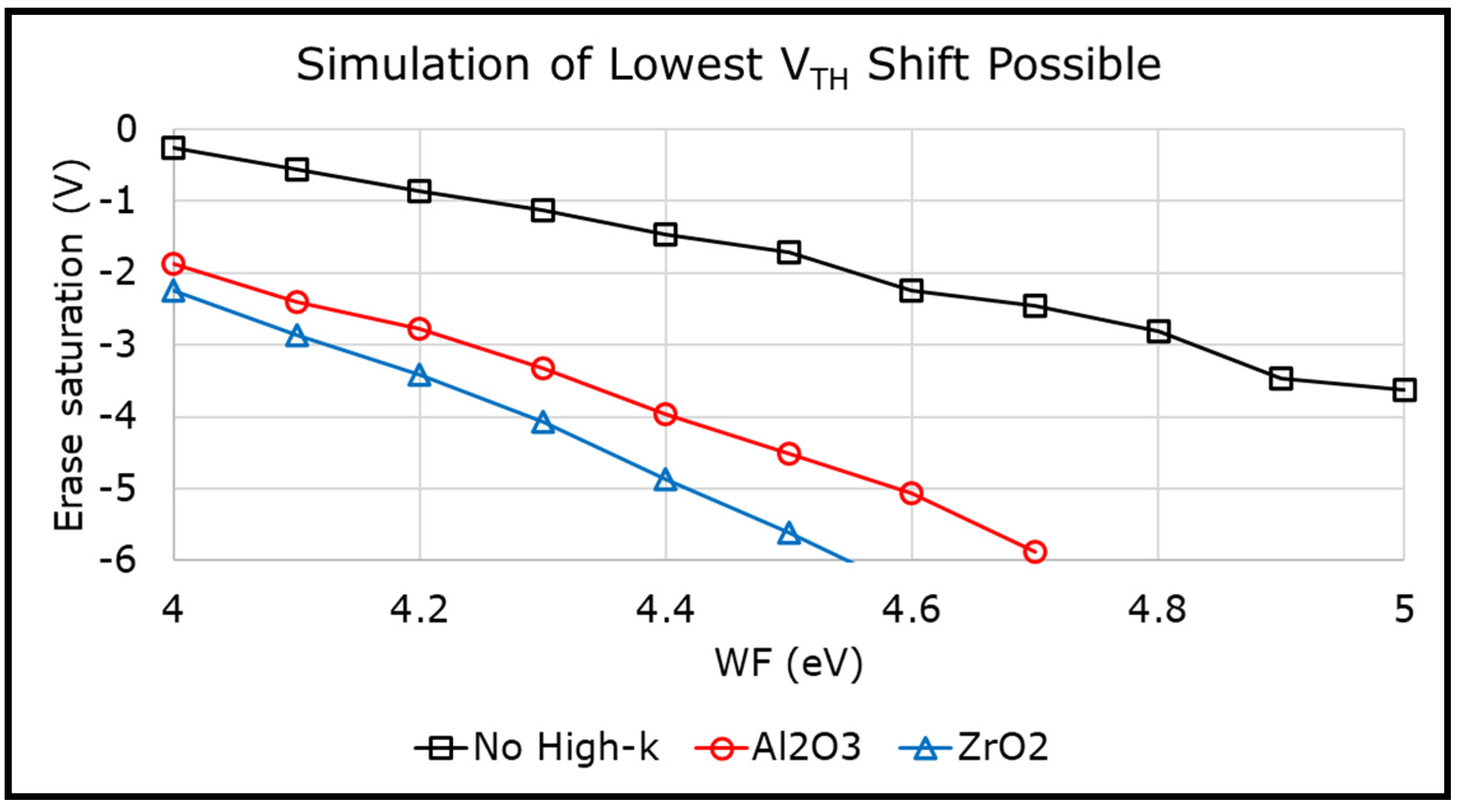
Figure 1. Simulations of erase saturation levels in a memory stack without high-k liner, or with 2 nm Al2O3 or ZrO2. Addition of a high-k liner shows more benefit than (work function) WF.
Micromachines 12 01084 g001
Figure 2. Schematic of the energy band diagram of a metal-insulator-semiconductor (MIS) capacitor.
Micromachines 12 01084 g002
Figure 3. Schematic of MIS capacitor with slant etch for SiO2. Corresponding oxide charge densities are indicated.
Micromachines 12 01084 g003
Figure 4. (a) Thickness of SiO2, after slant etch and plasma enhanced atomic layer deposition (PEALD) oxide deposition, measured across multiple wafers using ellipsometry; (b) Equivalent oxide thickness (EOT) computed from capacitance–voltage (CV) measurement. Bubble size represents EOT magnitude.
Micromachines 12 01084 g004
Figure 5. Schematic indicating different anneal types and the corresponding layers that received the process.
Micromachines 12 01084 g005
Figure 6. The VFB measured from CV is plotted as a function of SiO2 thickness. A second order fit is performed to isolate the terms p and q containing the charge densities in its bulk and interface.
Micromachines 12 01084 g006
Figure 7. The intercepts from the part 1 fit are plotted as a function of high-k EOT. A second order fit is performed to extract the metal work function.
Micromachines 12 01084 g007
Figure 8. (a) Cross-section schematic of the memory gate stack in a vertical three-dimensional (3D) NAND device; (b) schematic of a planar test structure used in this work. The components of the gate stack are indicated in the figure.
Micromachines 12 01084 g008
Figure 9. (a) Transmission electron microscope (TEM) image of a memory stack fabricated in this work; (b) different anneal types and the corresponding MHONOS layers that received the anneal.
Micromachines 12 01084 g009
Figure 10. Metal work function listed for a few metal/high-k combinations from this work. No high temperature anneals were performed for these stacks.
Micromachines 12 01084 g010
Figure 11. Incremental Step Pulse Erase (ISPE) of (Metal/High-k/ONO/Si) MHONOS, for different metal/high-k combinations from Figure 10.
Micromachines 12 01084 g011
Figure 12. WF extracted for multiple metal and high-k combinations after different annealing conditions. (a) Ru with HfO2; (b) Ru, Mo with ZrO2, and TiN with Al2O3.
Micromachines 12 01084 g012
Figure 13. ISPE of MHONOS stacks for (a) Ru/HfO2. Erase performance degrades with post metallization anneal (PMA) while no change after a post high-k deposition anneal (PDA); (b) Ru and Mo with ZrO2 and TiN with Al2O3. Similar degradation after PMA as in the case with HfO2. However, worse performance with Al2O3.
Micromachines 12 01084 g013
Figure 14. A typical band diagram of MHONOS during erase. Higher trap density reduces the tunneling path for gate electrons resulting in poor erase.
Micromachines 12 01084 g014
Figure 15. Schematic of MHONOS stacks with dipole-forming interlayers at different locations. Al2O3 and La2O3, each 0.6 nm thin, were used as interlayers with HfO2 used for high-k value.
Micromachines 12 01084 g015
Figure 16. Flat band voltage monitored from CV traces, for MHONOS stacks with different dipole interlayers from Figure 15 (a) without any PMA and (b) with PMA for 20 min at 750 °C in N2 ambient.
Micromachines 12 01084 g016
Figure 17. ISPE of MHONOS, for metal/high-k combinations from Figure 16. (a) Without any PMA; (b) with PMA for 20 min at 750 °C in N2 ambient.
Micromachines 12 01084 g017
Publisher’s Note: MDPI stays neutral with regard to jurisdictional claims in published maps and institutional affiliations.