Overview of Ultrasound Detection Technologies for Photoacoustic Imaging


Abstract
1. Introduction
2. Ultrasound Transducer Characteristics
3. Physical Ultrasound Transducer Technologies
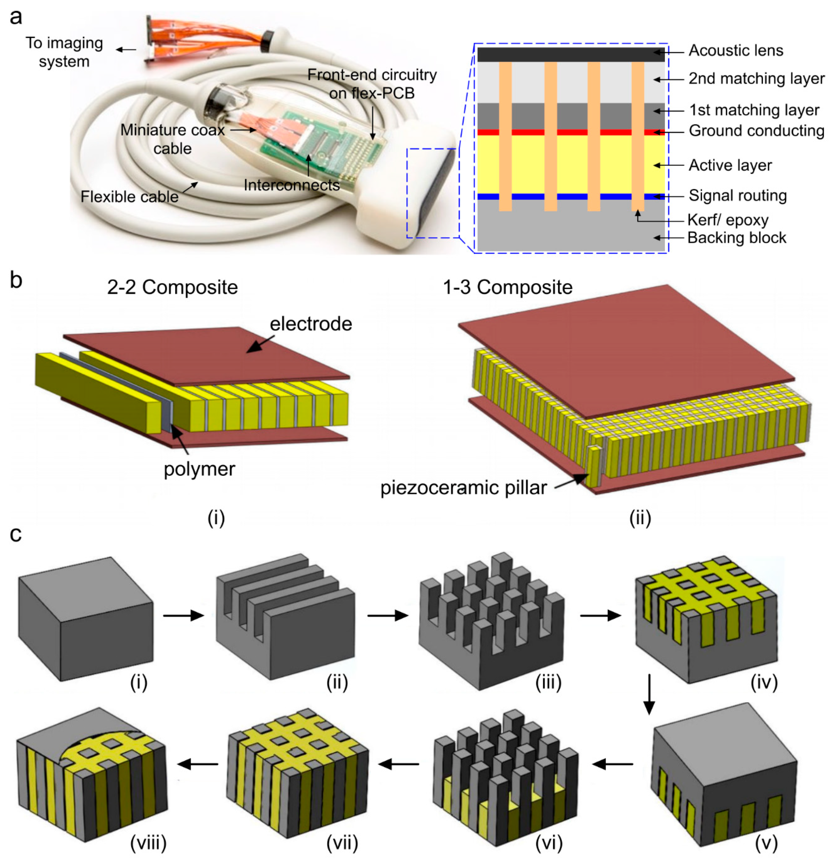
3.1. Piezoelectric Transducers
3.2. Micromachined Ultrasonic Transducers
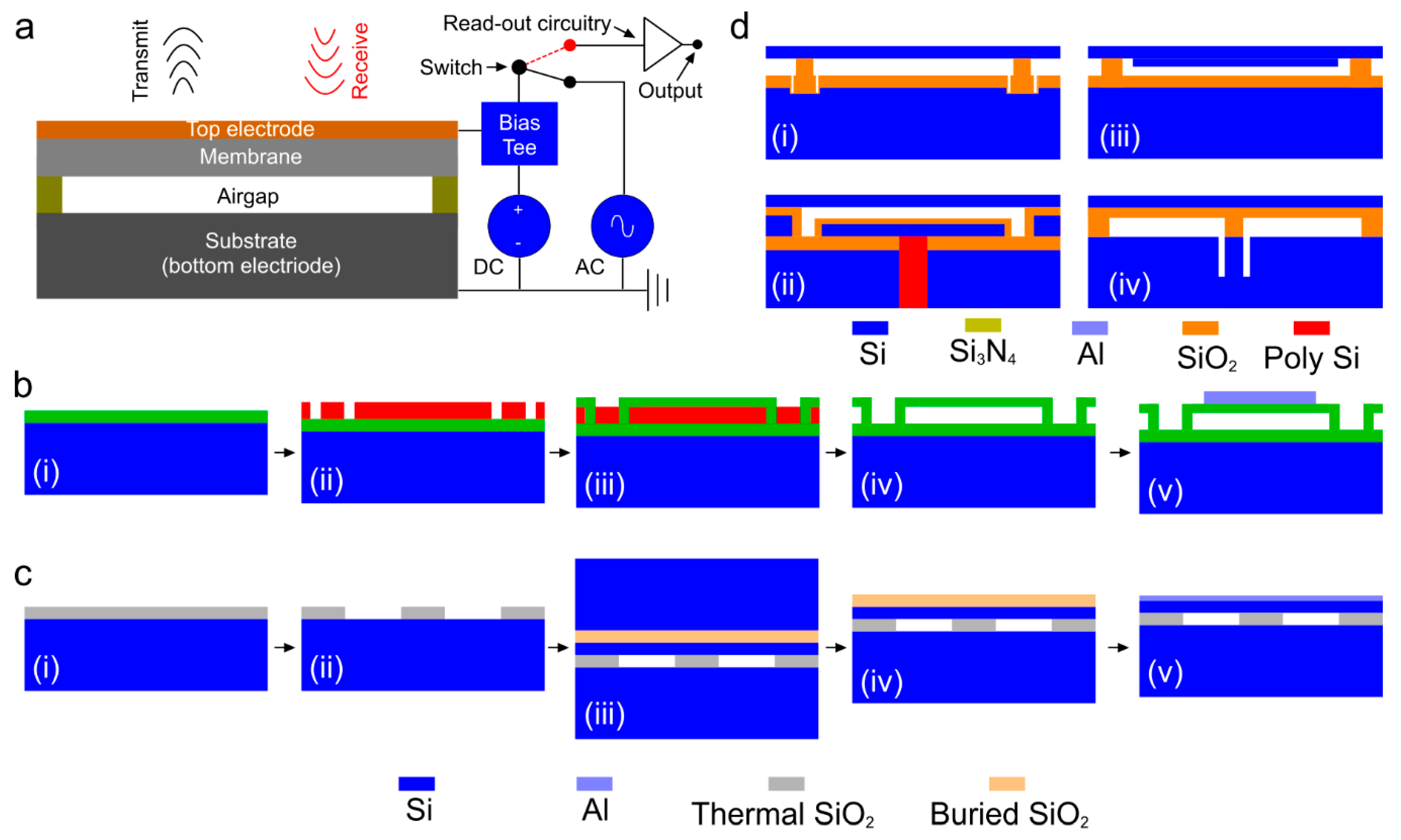
3.2.1. Capacitive Micromachined Ultrasonic Transducer (CMUT)
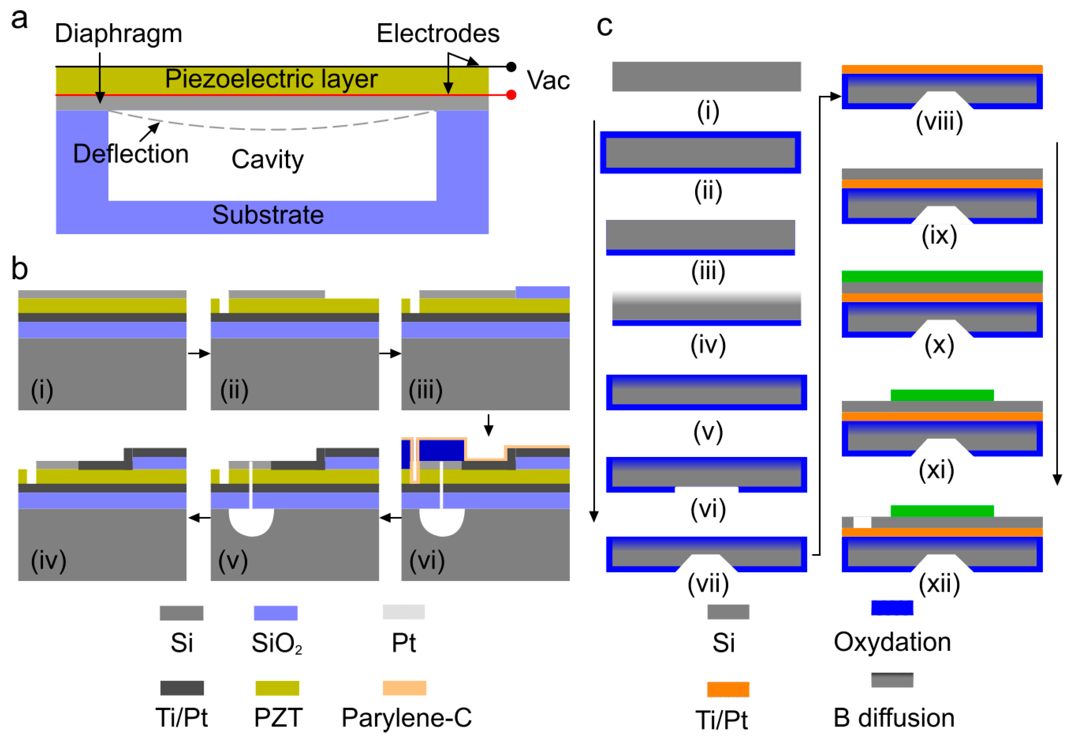
3.2.2. Piezoelectric Micromachined Ultrasonic Transducer (PMUT)
3.2.3. ASIC Technology in Physical Ultrasound Transducers
3.3. Comparison between Physical Ultrasound Transducer Technologies
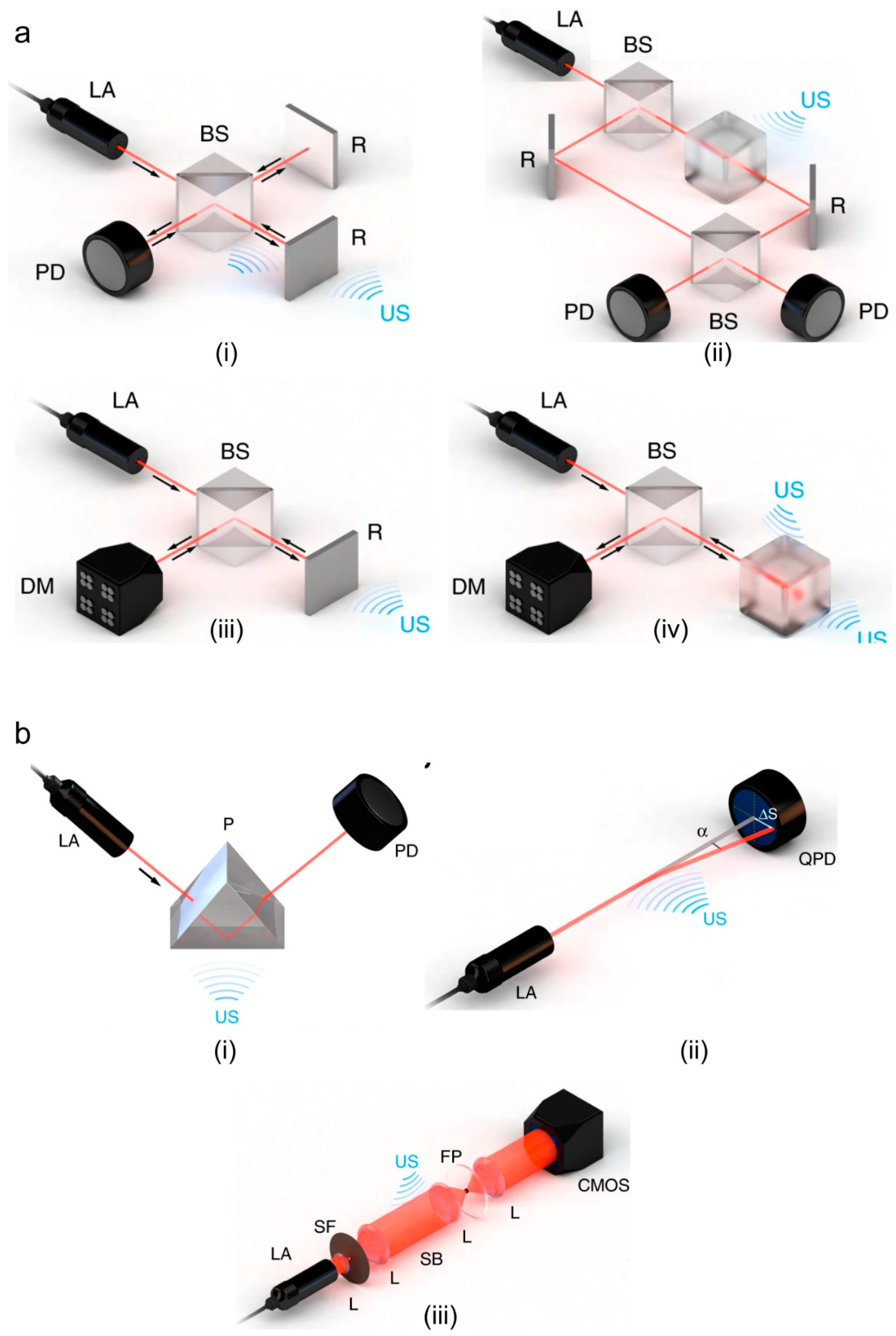
4. Optical Ultrasound Detection Technologies
5. Discussion and Conclusions
Author Contributions
Funding
Conflicts of Interest
References
- Dance, D.R.; Christofides, S.; Maidment, A.; McLean, I.; Ng, K. Diagnostic Radiology Physics: A Handbook for Teachers and Students. Endorsed by: American Association of Physicists in Medicine, Asia-Oceania Federation of Organizations for Medical Physics, European Federation of Organisations for Medical Physics; International Atomic Energy Agency (IAEA): Vienna, Austria, 2014. [Google Scholar]
- Wang, L.V. Tutorial on photoacoustic microscopy and computed tomography. IEEE J. Sel. Top. Quantum Electron. 2008, 14, 171–179. [Google Scholar] [CrossRef]
- Wang, L.V.; Hu, S. Photoacoustic tomography: In vivo imaging from organelles to organs. Science 2012, 335, 1458–1462. [Google Scholar] [CrossRef] [PubMed]
- Xia, J.; Yao, J.; Wang, L.V. Photoacoustic tomography: Principles and advances. Electromagn. Waves (Camb.) 2014, 147, 1–22. [Google Scholar] [CrossRef] [PubMed]
- Yao, J.; Wang, L.V. Photoacoustic microscopy. Laser Photonics Rev. 2013, 7, 758–778. [Google Scholar] [CrossRef] [PubMed]
- Zhou, Y.; Yao, J.; Wang, L.V. Tutorial on photoacoustic tomography. J. Biomed. Opt. 2016, 21, 061007. [Google Scholar] [CrossRef]
- Manwar, R.; Hosseinzadeh, M.; Hariri, A.; Kratkiewicz, K.; Noei, S.; Avanaki, M.N. Photoacoustic signal enhancement: Towards Utilization of low energy laser diodes in real-time photoacoustic imaging. Sensors 2018, 18, 3498. [Google Scholar] [CrossRef]
- Zafar, M.; Kratkiewicz, K.; Manwar, R.; Avanaki, M. Development of low-cost fast photoacoustic computed tomography: System characterization and phantom study. Appl. Sci. 2019, 9, 374. [Google Scholar] [CrossRef]
- Fatima, A.; Kratkiewicz, K.; Manwar, R.; Zafar, M.; Zhang, R.; Huang, B.; Dadashzadesh, N.; Xia, J.; Avanaki, M. Review of cost reduction methods in photoacoustic computed tomography. Photoacoustics 2019, 15, 100137. [Google Scholar] [CrossRef]
- Wang, L.V. Photoacoustic Imaging and Spectroscopy; CRC Press: Boca Raton, FL, USA, 2009. [Google Scholar]
- Wang, L.V.; Yao, J. A practical guide to photoacoustic tomography in the life sciences. Nat. Methods 2016, 13, 627. [Google Scholar] [CrossRef]
- Turani, Z.; Fatemizadeh, E.; Blumetti, T.; Daveluy, S.; Moraes, A.F.; Chen, W.; Mehregan, D.; Andersen, P.E.; Nasiriavanaki, M. Optical radiomic signatures derived from optical coherence tomography images improve identification of melanoma. Cancer Res. 2019, 79, 2021–2030. [Google Scholar] [CrossRef]
- Rayyan, A.; Karl, K.; Mohammad, R.N.A. Photoacoustic imaging: A promising alternative to transcranial ultrasound. Editor. Res. J. Photonics 2018, 2, 411–420. [Google Scholar]
- Zafar, M.; Kratkiewicz, K.; Manwar, R.; Avanaki, M. Low-cost fast photoacoustic computed tomography: Phantom study. In Proceedings of the Photons Plus Ultrasound: Imaging and Sensing 2019, San Francisco, CA, USA, 3–6 February 2019. [Google Scholar]
- Mozaffarzadeh, M.; Mahloojifar, A.; Orooji, M.; Adabi, S.; Nasiriavanaki, M. Double-stage delay multiply and sum beamforming algorithm: Application to linear-array photoacoustic imaging. IEEE Trans. Biomed. Eng. 2018, 65, 31–42. [Google Scholar] [CrossRef]
- Mozaffarzadeh, M.; Mahloojifar, A.; Orooji, M.; Kratkiewicz, K.; Adabi, S.; Nasiriavanaki, M. Linear-array photoacoustic imaging using minimum variance-based delay multiply and sum adaptive beamforming algorithm. J. Biomed. Opt. 2018, 23, 026002. [Google Scholar] [CrossRef] [PubMed]
- Omidi, P.; Zafar, M.; Mozaffarzadeh, M.; Hariri, A.; Haung, X.; Orooji, M.; Nasiriavanaki, M. A novel dictionary-based image reconstruction for photoacoustic computed tomography. Appl. Sci. 2018, 8, 1570. [Google Scholar] [CrossRef]
- Nasiriavanaki, M.; Xia, J.; Wan, H.; Bauer, A.Q.; Culver, J.P.; Wang, L.V. High-resolution photoacoustic tomography of resting-state functional connectivity in the mouse brain. Proc. Natl. Acad. Sci. USA 2014, 111, 21–26. [Google Scholar] [CrossRef] [PubMed]
- Upputuri, P.K.; Periyasamy, V.; Kalva, S.K.; Pramanik, M. A High-performance Compact Photoacoustic Tomography System for In Vivo Small-animal Brain Imaging. J. Vis. Exp. 2017, 124, e55811. [Google Scholar] [CrossRef]
- Xia, J.; Wang, L.V. Small-Animal Whole-Body Photoacoustic Tomography: A Review. IEEE Trans. Biomed. Eng. 2014, 61, 1380–1389. [Google Scholar] [CrossRef] [PubMed]
- Upputuri, P.K.; Pramanik, M. Dynamic in vivo imaging of small animal brain using pulsed laser diode-based photoacoustic tomography system. J. Biomed. Opt. 2017, 22, 1. [Google Scholar] [CrossRef] [PubMed]
- Upputuri, P.K.; Pramanik, M. Photoacoustic imaging in the second near-infrared window: A review. J. Biomed. Opt. 2019, 24, 1–20. [Google Scholar] [CrossRef]
- Liu, W.; Zhang, H.F. Photoacoustic imaging of the eye: A mini review. Photoacoustics 2016, 4, 112–123. [Google Scholar] [CrossRef]
- Silverman, R.H.; Kong, F.; Chen, Y.; Lloyd, H.O.; Kim, H.H.; Cannata, J.M.; Shung, K.K.; Coleman, D.J. High-Resolution Photoacoustic Imaging of Ocular Tissues. Ultrasound Med. Boil. 2010, 36, 733–742. [Google Scholar] [CrossRef] [PubMed]
- Nguyen, V.P.; Paulus, Y.M. Photoacoustic Ophthalmoscopy: Principle, Application, and Future Directions. J. Imaging 2018, 4, 149. [Google Scholar] [CrossRef] [PubMed]
- Jeon, S.; Song, H.B.; Kim, J.; Lee, B.J.; Managuli, R.; Kim, J.H.; Kim, J.H.; Kim, C. In Vivo Photoacoustic Imaging of Anterior Ocular Vasculature: A Random Sample Consensus Approach. Sci. Rep. 2017, 7, 4318. [Google Scholar] [CrossRef]
- Wang, S.; Lin, J.; Wang, T.; Chen, X.; Huang, P. Recent Advances in Photoacoustic Imaging for Deep-Tissue Biomedical Applications. Theranostics 2016, 6, 2394–2413. [Google Scholar] [CrossRef]
- Mehrmohammadi, M.; Yoon, S.J.; Yeager, D.; Emelianov, S.Y. Photoacoustic Imaging for Cancer Detection and Staging. Curr. Mol. Imaging 2013, 2, 89–105. [Google Scholar] [CrossRef] [PubMed]
- Oh, J.-T.; Li, M.-L.; Zhang, H.F.; Maslov, K.; Stoica, G.; Wang, L.V. Three-dimensional imaging of skin melanoma in vivo by dual-wavelength photoacoustic microscopy. J. Biomed. Opt. 2006, 11, 034032. [Google Scholar] [CrossRef]
- Rao, A.P.; Bokde, N.D.; Sinha, S. Photoacoustic Imaging for Management of Breast Cancer: A Literature Review and Future Perspectives. Appl. Sci. 2020, 10, 767. [Google Scholar] [CrossRef]
- Steinberg, I.; Huland, D.M.; Vermesh, O.; Frostig, H.E.; Tummers, W.S.; Gambhir, S.S. Photoacoustic clinical imaging. Photoacoustics 2019, 14, 77–98. [Google Scholar] [CrossRef]
- Fakhrejahani, E.; Torii, M.; Kitai, T.; Kanao, S.; Asao, Y.; Hashizume, Y.; Mikami, Y.; Yamaga, I.; Kataoka, M.; Sugie, T.; et al. Clinical Report on the First Prototype of a Photoacoustic Tomography System with Dual Illumination for Breast Cancer Imaging. PLoS ONE 2015, 10, e0139113. [Google Scholar] [CrossRef]
- Brown, E.; Brunker, J.; Bohndiek, S. Photoacoustic imaging as a tool to probe the tumour microenvironment. Dis. Model. Mech. 2019, 12, dmm039636. [Google Scholar] [CrossRef]
- Valluru, K.S.; Willmann, J.K. Clinical photoacoustic imaging of cancer. Ultrason. 2016, 35, 267–280. [Google Scholar] [CrossRef] [PubMed]
- Zhang, C.; Zhang, Y.; Hong, K.; Zhu, S.; Wan, J. Photoacoustic and fluorescence imaging of cutaneous squamous cell carcinoma in living subjects using a probe targeting integrin αvβ6. Sci. Rep. 2017, 7, 42442. [Google Scholar] [CrossRef]
- Zhang, E.Z.; Považay, B.; Laufer, J.; Alex, A.; Hofer, B.; Pedley, B.; Glittenberg, C.; Treeby, B.; Cox, B.T.; Beard, P.; et al. Multimodal photoacoustic and optical coherence tomography scanner using an all optical detection scheme for 3D morphological skin imaging. Biomed. Opt. Express 2011, 2, 2202–2215. [Google Scholar] [CrossRef] [PubMed]
- Guo, B.; Sheng, Z.; Hu, D.; Liu, C.; Wang, X.; Liu, B. Through Scalp and Skull NIR-II Photothermal Therapy of Deep Orthotopic Brain Tumors with Precise Photoacoustic Imaging Guidance. Adv. Mater. 2018, 30, e1802591. [Google Scholar] [CrossRef] [PubMed]
- Joshi, B.P.; Wang, T.D. Targeted Optical Imaging Agents in Cancer: Focus on Clinical Applications. Contrast Media Mol. Imaging 2018, 2018, 1–19. [Google Scholar] [CrossRef]
- Lee, W.; Roh, Y. Ultrasonic transducers for medical diagnostic imaging. Biomed. Eng. Lett. 2017, 7, 91–97. [Google Scholar] [CrossRef]
- Jung, J.; Lee, W.; Kang, W.; Shin, E.; Ryu, J.; Choi, H. Review of piezoelectric micromachined ultrasonic transducers and their applications. J. Micromech. Microeng. 2017, 27, 113001. [Google Scholar] [CrossRef]
- Dong, B.; Sun, C.; Zhang, H.F. Optical detection of ultrasound in photoacoustic imaging. IEEE Trans. Biomed. Eng. 2017, 64, 4–15. [Google Scholar] [CrossRef]
- Wissmeyer, G.; Pleitez, M.A.; Rosenthal, A.; Ntziachristos, V. Looking at sound: Optoacoustics with all-optical ultrasound detection. Light Sci. Appl. 2018, 7, 53. [Google Scholar] [CrossRef]
- Vallet, M.; Varray, F.; Boutet, J.; Dinten, J.-M.; Caliano, G.; Savoia, A.S.; Vray, D. Quantitative comparison of PZT and CMUT probes for photoacoustic imaging: Experimental validation. Photoacoustics 2017, 8, 48–58. [Google Scholar] [CrossRef]
- Jiang, X.; Al-Jumaily, A.M. Ultrasound transducers for biomedical imaging and therapy. J. Eng. Sci. Med. Diagn. Ther. 2018, 1, 040201. [Google Scholar] [CrossRef]
- Salim, M.S.; Abd Malek, M.F.; Heng, R.B.W.; Juni, K.M.; Sabri, N. Capacitive micromachined ultrasonic transducers: Technology and application. J. Med. Ultrasound 2012, 20, 8–31. [Google Scholar] [CrossRef]
- Khuri-Yakub, B.T.; Oralkan, O. Capacitive micromachined ultrasonic transducers for medical imaging and therapy. J. Micromech. Microeng. Struct. Devices Syst. 2011, 21, 54004–54014. [Google Scholar] [CrossRef] [PubMed]
- Duy Le, A. Investigation of Element Variations in Ultrasound Transducer Arrays by Electrical Impedance Measurements; Høgskolen i Sørøst-Norge: Notodden, Norway, 2016. [Google Scholar]
- Yaralioglu, G.G.; Ergun, A.S.; Bayram, B.; Haeggstrom, E.; Khuri-Yakub, B.T. Calculation and measurement of electromechanical coupling coefficient of capacitive micromachined ultrasonic transducers. IEEE Trans. Ultrason. Ferroelectr. Freq. Control 2003, 50, 449–456. [Google Scholar] [CrossRef] [PubMed]
- Yang, Y.; Wei, X.; Zhang, L.; Yao, W. The effect of electrical impedance matching on the electromechanical characteristics of sandwiched piezoelectric ultrasonic transducers. Sensors 2017, 17, 2832. [Google Scholar] [CrossRef] [PubMed]
- Rathod, V.T. A review of electric impedance matching techniques for piezoelectric sensors, actuators and transducers. Electronics 2019, 8, 169. [Google Scholar] [CrossRef]
- Ritter, T.; Shung, K.; Hackenberger, W.; Wang, H.; Shrout, T.R. Performance of a high dielectric constant piezoelectric ceramic for ultrasound transducers. In Proceedings of the 1999 IEEE Ultrasonics Symposium. Proceedings. International Symposium (Cat. No. 99CH37027), Caesars Tahoe, NV, USA, 17–20 October 1999. [Google Scholar]
- Winkler, A.M.; Maslov, K.I.; Wang, L.V. Noise-equivalent sensitivity of photoacoustics. J. Biomed. Opt. 2013, 18, 097003. [Google Scholar] [CrossRef]
- Yao, J.; Wang, L.V. Sensitivity of photoacoustic microscopy. Photoacoustics 2014, 2, 87–101. [Google Scholar] [CrossRef]
- Zhou, Q.; Lam, K.H.; Zheng, H.; Qiu, W.; Shung, K.K. Piezoelectric single crystal ultrasonic transducers for biomedical applications. Prog. Mater. Sci. 2014, 66, 87–111. [Google Scholar] [CrossRef] [PubMed]
- Szabo, T.L.; Lewin, P.A. Ultrasound transducer selection in clinical imaging practice. J. Ultrasound Med. 2013, 32, 573–582. [Google Scholar] [CrossRef]
- Zhang, J.X.J.; Hoshino, K. Molecular Sensors and Nanodevices: Principles, Designs and Applications in Biomedical Engineering; Academic Press: Cambridge, MA, USA, 2018. [Google Scholar]
- Lerch, R. Finite element analysis of piezoelectric transducers. In Proceedings of the IEEE 1988 Ultrasonics Symposium Proceedings, Chicago, IL, USA, 2–5 October 1988. [Google Scholar]
- Loveday, P.W. Analysis of piezoelectric ultrasonic transducers attached to waveguides using waveguide finite elements. IEEE Trans. Ultrason. Ferroelectr. Freq. Control 2007, 54, 2045–2051. [Google Scholar] [CrossRef] [PubMed]
- Hepher, M.J. Natural and synthetic piezoelectric materials for chemical sensors. In Proceedings of the 1992 Sixth International Conference on Dielectric Materials, Measurements and Applications, Manchester, UK, 7–10 September 1992. [Google Scholar]
- Kumar, P.; Singh, S.; Thakur, O.P.; Prakash, C.; Goel, T.C. Study of lead magnesium niobate–lead titanate ceramics for piezo-actuator applications. Jpn. J. Appl. Phys. 2004, 43, 1501. [Google Scholar] [CrossRef]
- Ren, W.; Liu, S.-F.; Mukherjee, B.K. Nonlinear behavior of piezoelectric lead zinc niobate-lead titanate single crystals under AC electric fields. In Proceedings of the Smart Structures and Materials 2003: Active Materials: Behavior and Mechanics, San Diego, CA, USA, 3–6 March 2003. [Google Scholar]
- Lee, H.J.; Zhang, S.; Bar-Cohen, Y.; Sherrit, S. High temperature, high power piezoelectric composite transducers. Sensors 2014, 14, 14526–14552. [Google Scholar] [CrossRef] [PubMed]
- Huang, Q.; Wang, H.; Hao, S.; Zhong, C.; Wang, L. Design and fabrication of a high-frequency single-directional planar underwater ultrasound transducer. Sensors 2019, 19, 4336. [Google Scholar] [CrossRef]
- Acosta, M.; Novak, N.; Rojas, V.; Patel, S.; Vaish, R.; Koruza, J.; Rossetti, G., Jr.; Rödel, J. BaTiO3-based piezoelectrics: Fundamentals, current status, and perspectives. Appl. Phys. Rev. 2017, 4, 041305. [Google Scholar] [CrossRef]
- Bordui, P.F.; Norwood, R.; Jundt, D.H.; Fejer, M. Preparation and characterization of off-congruent lithium niobate crystals. J. Appl. Phys. 1992, 71, 875–879. [Google Scholar] [CrossRef]
- Yamada, T.; Niizeki, N.; Toyoda, H. Piezoelectric and elastic properties of lithium niobate single crystals. Jpn. J. Appl. Phys. 1967, 6, 151. [Google Scholar] [CrossRef]
- Sengupta, P.; Khanra, K.; Chowdhury, A.R.; Datta, P. 4—Lab-on-a-chip sensing devices for biomedical applications. In Bioelectronics and Medical Devices; Pal, K., Ed.; Woodhead Publishing: Sawston, UK, 2019; pp. 47–95. [Google Scholar]
- Denishev, K. Some metal oxides and their applications for creation of Microsystems (MEMS) and Energy Harvesting Devices (EHD). J. Phys. Conf. Ser. 2016, 764, 012003. [Google Scholar] [CrossRef]
- Safari, A.; Akdogan, E.K. Piezoelectric and Acoustic Materials for Transducer Applications; Springer Science & Business Media: Berlin/Heidelberg, Germany, 2008. [Google Scholar]
- Ketterling, J.A.; Aristizabal, O.; Turnbull, D.H.; Lizzi, F.L. Design and fabrication of a 40-MHz annular array transducer. IEEE Trans. Ultrason. Ferroelectr. Freq. Control 2005, 52, 672–681. [Google Scholar] [CrossRef]
- Sherar, M.D.; Foster, F.S. The design and fabrication of high frequency poly (vinylidene fluoride) transducers. Ultrason. Imaging 1989, 11, 75–94. [Google Scholar] [CrossRef]
- Sherar, M.D.; Foster, F.S. A 100 MHz PVDF ultrasound microscope with biological applications. In Acoustical Imaging; Springer: Berlin/Heidelberg, Germany, 1988; pp. 511–520. [Google Scholar]
- Foster, F.S.; Harasiewicz, K.A.; Sherar, M.D. A history of medical and biological imaging with polyvinylidene fluoride (PVDF) transducers. IEEE Trans. Ultrason. Ferroelectr. Freq. Control 2000, 47, 1363–1371. [Google Scholar] [CrossRef]
- Decharat, A.; Wagle, S.; Melandsø, F. Effect of polymer electrode thickness on the acoustical properties of all-screen printed piezoelectric pvdf copolymer transducers. Jpn. J. Appl. Phys. 2014, 53, 05HB16. [Google Scholar] [CrossRef]
- Safari, A. Development of piezoelectric composites for transducers. J. Phys. III 1994, 4, 1129–1149. [Google Scholar] [CrossRef]
- Sun, R.; Wang, L.; Zhang, Y.; Zhong, C. Characterization of 1-3 piezoelectric composite with a 3-tier polymer structure. Materials 2020, 13, 397. [Google Scholar] [CrossRef] [PubMed]
- Goldberg, R.L.; Smith, S.W. Multilayer piezoelectric ceramics for two-dimensional array transducers. IEEE Trans. Ultrason. Ferroelectr. Freq. Control 1994, 41, 761–771. [Google Scholar] [CrossRef]
- Martin, K.H.; Lindsey, B.D.; Ma, J.; Lee, M.; Li, S.; Foster, F.S.; Jiang, X.; Dayton, P.A. Dual-frequency piezoelectric transducers for contrast enhanced ultrasound imaging. Sensors 2014, 14, 20825–20842. [Google Scholar] [CrossRef]
- Muralt, P.; Ledermann, N.; Paborowski, J.; Barzegar, A.; Gentil, S.; Belgacem, B.; Petitgrand, S.; Bosseboeuf, A.; Setter, N. Piezoelectric micromachined ultrasonic transducers based on PZT thin films. IEEE Trans. Ultrason. Ferroelectr. Freq. Control 2005, 52, 2276–2288. [Google Scholar] [CrossRef]
- Zipparo, M.J.; Shung, K.K.; Shrout, T.R. Piezoceramics for high-frequency (20 to 100 MHz) single-element imaging transducers. IEEE Trans. Ultrason. Ferroelectr. Freq. Control 1997, 44, 1038–1048. [Google Scholar] [CrossRef]
- Newnham, R.E.; Skinner, D.P.; Cross, L.E. Connectivity and piezoelectric-pyroelectric composites. Mater. Res. Bull. 1978, 13, 525–536. [Google Scholar] [CrossRef]
- Cross, L.E. Ferroelectric materials for electromechanical transducer applications. Mater. Chem. Phys. 1996, 43, 108–115. [Google Scholar] [CrossRef]
- Silva, E.C.N.; Fonseca, J.O.; de Espinosa, F.M.; Crumm, A.; Brady, G.; Halloran, J.; Kikuchi, N. Design of piezocomposite materials and piezoelectric transducers using topology optimization—Part I. Arch. Comput. Methods Eng. 1999, 6, 117–182. [Google Scholar] [CrossRef]
- Levassort, F.; Tran-Huu-Hue, L.P.; Certon, D.; Lethiecq, M. Piezoelectric Materials for Ultrasonic Transducers: Review of Recent Developments; Laboratoire d‘Ultrasons, Signaux et Instrumentation, GIP Ultrasons: Blois, France, 2002. [Google Scholar]
- Hackenberger, W.; Rehrig, P.W.; Ritter, T.; Shrout, T. Advanced piezoelectric materials for medical ultrasound transducers. In Proceedings of the 2001 IEEE Ultrasonics Symposium. Proceedings. An International Symposium (Cat. No. 01CH37263), Atlanta, GA, USA, 7–10 October 2001. [Google Scholar]
- Thippabhotla, S.; Zhong, C.; He, M. 3D cell culture stimulates the secretion of in vivo like extracellular vesicles. Sci. Rep. 2019, 9, 13012. [Google Scholar] [CrossRef] [PubMed]
- Heijblom, M.; Piras, D.; van den Engh, F.M.; van der Schaaf, M.; Klaase, J.M.; Steenbergen, W.; Manohar, S. The state of the art in breast imaging using the Twente Photoacoustic Mammoscope: Results from 31 measurements on malignancies. Eur. Radiol. 2016, 26, 3874–3887. [Google Scholar] [CrossRef]
- Toi, M.; Asao, Y.; Matsumoto, Y.; Sekiguchi, H.; Yoshikawa, A.; Takada, M.; Kataoka, M.; Endo, T.; Kawaguchi-Sakita, N.; Kawashima, M. Visualization of tumor-related blood vessels in human breast by photoacoustic imaging system with a hemispherical detector array. Sci. Rep. 2017, 7, 41970. [Google Scholar] [CrossRef]
- Ermilov, S.A.; Khamapirad, T.; Conjusteau, A.; Leonard, M.H.; Lacewell, R.; Mehta, K.; Miller, T.; Oraevsky, A.A. Laser optoacoustic imaging system for detection of breast cancer. J. Biomed. Opt. 2009, 14, 024007. [Google Scholar] [CrossRef] [PubMed]
- Schwarz, M.; Buehler, A.; Aguirre, J.; Ntziachristos, V. Three-dimensional multispectral optoacoustic mesoscopy reveals melanin and blood oxygenation in human skin in vivo. J. Biophotonics 2016, 9, 55–60. [Google Scholar] [CrossRef] [PubMed]
- Aguirre, J.; Schwarz, M.; Soliman, D.; Buehler, A.; Omar, M.; Ntziachristos, V. Broadband mesoscopic optoacoustic tomography reveals skin layers. Opt. Lett. 2014, 39, 6297–6300. [Google Scholar] [CrossRef]
- Petri, M.; Stoffels, I.; Jose, J.; Leyh, J.; Schulz, A.; Dissemond, J.; Schadendorf, D.; Klode, J. Photoacoustic imaging of real-time oxygen changes in chronic leg ulcers after topical application of a haemoglobin spray: A pilot study. J. Wound Care 2016, 25, 87–89. [Google Scholar] [CrossRef]
- Favazza, C.P.; Jassim, O.; Cornelius, L.A.; Wang, L.V. In vivo photoacoustic microscopy of human cutaneous microvasculature and a nevus. J. Biomed. Opt. 2011, 16, 016015. [Google Scholar] [CrossRef]
- Dima, A.; Ntziachristos, V. Non-invasive carotid imaging using optoacoustic tomography. Opt. Express 2012, 20, 25044–25057. [Google Scholar] [CrossRef]
- Seeger, M.; Karlas, A.; Soliman, D.; Pelisek, J.; Ntziachristos, V. Multimodal optoacoustic and multiphoton microscopy of human carotid atheroma. Photoacoustics 2016, 4, 102–111. [Google Scholar] [CrossRef]
- Van Es, P.; Biswas, S.K.; Moens, H.J.B.; Steenbergen, W.; Manohar, S. Initial results of finger imaging using photoacoustic computed tomography. J. Biomed. Opt. 2014, 19, 060501. [Google Scholar] [CrossRef] [PubMed]
- Yuan, J.; Xu, G.; Yu, Y.; Zhou, Y.; Carson, P.L.; Wang, X.; Liu, X. Real-time photoacoustic and ultrasound dual-modality imaging system facilitated with graphics processing unit and code parallel optimization. J. Biomed. Opt. 2013, 18, 086001. [Google Scholar] [CrossRef] [PubMed]
- Buehler, A.; Diot, G.; Volz, T.; Kohlmeyer, J.; Ntziachristos, V. Imaging of fatty tumors: Appearance of subcutaneous lipomas in optoacoustic images. J. Biophotonics 2017, 10, 983–989. [Google Scholar] [CrossRef] [PubMed]
- Reber, J.; Willershäuser, M.; Karlas, A.; Paul-Yuan, K.; Diot, G.; Franz, D.; Fromme, T.; Ovsepian, S.V.; Bézière, N.; Dubikovskaya, E. Non-invasive measurement of brown fat metabolism based on optoacoustic imaging of hemoglobin gradients. Cell Metab. 2018, 27, 689–701. [Google Scholar] [CrossRef] [PubMed]
- Yang, M.; Zhao, L.; He, X.; Su, N.; Zhao, C.; Tang, H.; Hong, T.; Li, W.; Yang, F.; Lin, L. Photoacoustic/ultrasound dual imaging of human thyroid cancers: An initial clinical study. Biomed. Opt. Express 2017, 8, 3449–3457. [Google Scholar] [CrossRef] [PubMed]
- Dima, A.; Ntziachristos, V. In-vivo handheld optoacoustic tomography of the human thyroid. Photoacoustics 2016, 4, 65–69. [Google Scholar] [CrossRef] [PubMed]
- Nedosekin, D.A.; Sarimollaoglu, M.; Ye, J.H.; Galanzha, E.I.; Zharov, V.P. In vivo ultra-fast photoacoustic flow cytometry of circulating human melanoma cells using near-infrared high-pulse rate lasers. Cytom. Part A 2011, 79, 825–833. [Google Scholar] [CrossRef]
- Horiguchi, A.; Tsujita, K.; Irisawa, K.; Kasamatsu, T.; Hirota, K.; Kawaguchi, M.; Shinchi, M.; Ito, K.; Asano, T.; Shinmoto, H. A pilot study of photoacoustic imaging system for improved real-time visualization of neurovascular bundle during radical prostatectomy. Prostate 2016, 76, 307–315. [Google Scholar] [CrossRef]
- Manwar, R. A BCB Diaphragm Based Adhesive Wafer Bonded CMUT Probe for Biomedical Application. Ph.D. Thesis, University of Windsor, Windsor, ON, Canada, 2017. [Google Scholar]
- Leondes, C.T. Mems/Nems:(1) Handbook Techniques and Applications Design Methods,(2) Fabrication Techniques,(3) Manufacturing Methods,(4) Sensors and Actuators,(5) Medical Applications and MOEMS; Springer Science & Business Media: Berlin/Heidelberg, Germany, 2007. [Google Scholar]
- Soumia, E.H.; Mohamad, E. Recent Advances in Electrical and Information Technologies for Sustainable Development; Springer International Publishing: Cham, Switzerland, 2019. [Google Scholar]
- Liu, C.; Djuth, F.T.; Zhou, Q.; Shung, K.K. Micromachining techniques in developing high-frequency piezoelectric composite ultrasonic array transducers. IEEE Trans. Ultrason. Ferroelectr. Freq. Control 2013, 60, 2615–2625. [Google Scholar]
- Oralkan, O.; Ergun, A.S.; Johnson, J.A.; Karaman, M.; Demirci, U.; Kaviani, K.; Lee, T.H.; Khuri-Yakub, B.T. Capacitive micromachined ultrasonic transducers: Next-generation arrays for acoustic imaging? IEEE Trans. Ultrason. Ferroelectr. Freq. Control 2002, 49, 1596–1610. [Google Scholar] [CrossRef]
- Manwar, R.; Chowdhury, S. Experimental analysis of bisbenzocyclobutene bonded capacitive micromachined ultrasonic transducers. Sensors 2016, 16, 959. [Google Scholar] [CrossRef] [PubMed]
- Li, Z.; Wong, L.L.; Chen, A.I.; Na, S.; Sun, J.; Yeow, J.T. Fabrication of capacitive micromachined ultrasonic transducers based on adhesive wafer bonding technique. J. Micromech. Microeng. 2016, 26, 115019. [Google Scholar] [CrossRef]
- Manwar, R.; Simpson, T.; Bakhtazad, A.; Chowdhury, S. Fabrication and characterization of a high frequency and high coupling coefficient CMUT array. Microsyst. Technol. 2017, 23, 4965–4977. [Google Scholar] [CrossRef]
- Kupnik, M.; Vaithilingam, S.; Torashima, K.; Wygant, I.O.; Khuri-Yakub, B.T. CMUT fabrication based on a thick buried oxide layer. In Proceedings of the 2010 IEEE International Ultrasonics Symposium, San Diego, CA, USA, 11–14 October 2010. [Google Scholar]
- Huang, Y.; Zhuang, X.; Haeggstrom, E.O.; Ergun, A.S.; Cheng, C.H.; Khuri-Yakub, B.T. Capacitive micromachined ultrasonic transducers with piston-shaped membranes: Fabrication and experimental characterization. IEEE Trans. Ultrason. Ferroelectr. Freq. Control 2009, 56, 136–145. [Google Scholar] [CrossRef] [PubMed]
- Nikoozadeh, A.; Khuri-Yakub, P.T. CMUT with substrate-embedded springs for non-flexural plate movement. In Proceedings of the IEEE Ultrasonics Symposium, San Diego, CA, USA, 11–14 October 2010; pp. 1510–1513. [Google Scholar]
- Erguri, A.S.; Huang, Y.; Zhuang, X.; Oralkan, O.; Yarahoglu, G.G.; Khuri-Yakub, B.T. Capacitive micromachined ultrasonic transducers: Fabrication technology. IEEE Trans. Ultrason. Ferroelectr. Freq. Control 2005, 52, 2242–2258. [Google Scholar] [CrossRef]
- Knight, J.; McLean, J.; Degertekin, F.L. Low temperature fabrication of immersion capacitive micromachined ultrasonic transducers on silicon and dielectric substrates. IEEE Trans. Ultrason. Ferroelectr. Freq. Control 2004, 51, 1324–1333. [Google Scholar] [CrossRef]
- Lin, D.; Zhuang, X.; Wong, S.H.; Ergun, A.S.; Kupnik, M.; Khuri-Yakub, B.T. 6F-5 Characterization of Fabrication Related Gap-Height Variations in Capacitive Micromachined Ultrasonic Transducers. In Proceedings of the 2007 IEEE Ultrasonics Symposium Proceedings, New York, NY, USA, 28–31 October 2007. [Google Scholar]
- Brenner, K.; Ergun, A.S.; Firouzi, K.; Rasmussen, M.F.; Stedman, Q.; Khuri-Yakub, B.P. Advances in capacitive micromachined ultrasonic transducers. Micromachines 2019, 10, 152. [Google Scholar] [CrossRef] [PubMed]
- Kothapalli, S.; Ma, T.-J.; Vaithilingam, S.; Oralkan, Ö.; Khuri-Yakub, B.T.; Gambhir, S.S. Deep tissue photoacoustic imaging using a miniaturized 2-D capacitive micromachined ultrasonic transducer array. IEEE Trans. Biomed. Eng. 2012, 59, 1199–1204. [Google Scholar] [CrossRef]
- Wygant, I.O.; Zhuang, X.; Kuo, P.; Yeh, D.; Oralkan, O.; Khuri-Yakub, B. Photoacoustic imaging using a two-dimensional CMUT array. In Proceedings of the IEEE Ultrasonics Symposium, Rotterdam, The Netherlands, 18–21 September 2005. [Google Scholar]
- Vaithilingam, S.; Ma, T.-J.; Furukawa, Y.; Wygant, I.O.; Zhuang, X.; De La Zerda, A.; Oralkan, O.; Kamaya, A.; Jeffrey, R.B.; Khuri-Yakub, B.T. Three-dimensional photoacoustic imaging using a two-dimensional CMUT array. IEEE Trans. Ultrason. Ferroelectr. Freq. Control 2009, 56, 2411–2419. [Google Scholar] [CrossRef]
- Mahmoodkalayeh, S.; Jooya, H.Z.; Hariri, A.; Zhou, Y.; Xu, Q.; Ansari, M.A.; Avanaki, M.R. Low temperature-mediated enhancement of photoacoustic imaging depth. Sci. Rep. 2018, 8, 4873. [Google Scholar] [CrossRef]
- Wygant, I.O.; Zhuang, X.; Yeh, D.T.; Oralkan, O.; Ergun, A.S.; Karaman, M.; Khuri-Yakub, B.T. Integration of 2D CMUT arrays with front-end electronics for volumetric ultrasound imaging. IEEE Trans. Ultrason. Ferroelectr. Freq. Control 2008, 55, 327–342. [Google Scholar] [CrossRef] [PubMed]
- Chee, R.K.W.; Sampaleanu, A.; Rishi, D.; Zemp, R.J. Top orthogonal to bottom electrode (TOBE) 2-D CMUT arrays for 3-D photoacoustic imaging. IEEE Trans. Ultrason. Ferroelectr. Freq. Control 2014, 61, 1393–1395. [Google Scholar] [CrossRef] [PubMed]
- Ma, T.-J.; Kothapalli, S.R.; Vaithilingam, S.; Oralkan, Ö.; Kamaya, A.; Wygant, I.O.; Zhuang, X.; Gambhir, S.S.; Jeffrey, R.B.; Khuri-Yakub, B.T. 3-D deep penetration photoacoustic imaging with a 2-D CMUT array. In Proceedings of the 2010 IEEE International Ultrasonics Symposium, San Diego, CA, USA, 11–14 October 2010. [Google Scholar]
- Chen, J.; Wang, M.; Cheng, J.-C.; Wang, Y.-H.; Li, P.-C.; Cheng, X. A photoacoustic imager with light illumination through an infrared-transparent silicon CMUT array. IEEE Trans. Ultrason. Ferroelectr. Freq. Control 2012, 59, 766–775. [Google Scholar] [CrossRef] [PubMed]
- Zhang, X.; Wu, X.; Adelegan, O.J.; Yamaner, F.Y.; Oralkan, Ö. Backward-mode photoacoustic imaging using illumination through a CMUT with improved transparency. IEEE Trans. Ultrason. Ferroelectr. Freq. Control 2017, 65, 85–94. [Google Scholar] [CrossRef]
- Li, Z.; Ilkhechi, A.K.; Zemp, R. Transparent capacitive micromachined ultrasonic transducers (CMUTs) for photoacoustic applications. Opt. Express 2019, 27, 13204–13218. [Google Scholar] [CrossRef]
- Matsumoto, Y.; Asao, Y.; Sekiguchi, H.; Yoshikawa, A.; Ishii, T.; Nagae, K.-I.; Kobayashi, S.; Tsuge, I.; Saito, S.; Takada, M. Visualising peripheral arterioles and venules through high-resolution and large-area photoacoustic imaging. Sci. Rep. 2018, 8, 1–11. [Google Scholar] [CrossRef]
- Qiu, Y.; Gigliotti, J.V.; Wallace, M.; Griggio, F.; Demore, C.E.; Cochran, S.; Trolier-McKinstry, S. Piezoelectric micromachined ultrasound transducer (PMUT) arrays for integrated sensing, actuation and imaging. Sensors 2015, 15, 8020–8041. [Google Scholar] [CrossRef]
- Griggio, F.; Demore, C.E.; Kim, H.; Gigliotti, J.; Qiu, Y.; Jackson, T.N.; Choi, K.; Tutwiler, R.L.; Cochran, S.; Trolier-McKinstry, S. Micromachined diaphragm transducers for miniaturised ultrasound arrays. In Proceedings of the 2012 IEEE International Ultrasonics Symposium, Dresden, Germany, 7–10 October 2012. [Google Scholar]
- Akasheh, F.; Myers, T.; Fraser, J.D.; Bose, S.; Bandyopadhyay, A. Development of piezoelectric micromachined ultrasonic transducers. Sens. Actuators A Phys. 2004, 111, 275–287. [Google Scholar] [CrossRef]
- Hajati, A.; Latev, D.; Gardner, D.; Hajati, A.; Imai, D.; Torrey, M.; Schoeppler, M. Three-dimensional micro electromechanical system piezoelectric ultrasound transducer. Appl. Phys. Lett. 2012, 101, 253101. [Google Scholar] [CrossRef]
- Dangi, A.; Cheng, C.; Agrawal, S.; Tiwari, S.; Datta, G.R.; Benoit, R.; Pratap, R.; Trolier-McKinstry, S.; Kothapalli, S.-R. A photoacoustic imaging device using Piezoelectric Micromachined Ultrasound Transducers (PMUTs). IEEE Trans. Ultrason. Ferroelectr. Freq. Control 2020, 67, 801–809. [Google Scholar] [CrossRef] [PubMed]
- Dangi, A.; Agrawal, S.; Tiwari, S.; Jadhav, S.; Cheng, C.; Trolier-McKinstry, S.; Pratap, R.; Kothapalli, S.-R. Evaluation of high frequency piezoelectric micromachined ultrasound transducers for photoacoustic imaging. In Proceedings of the 2018 IEEE SENSORS, New Delhi, India, 28–31 October 2018. [Google Scholar]
- Dausch, D.E.; Gilchrist, K.H.; Carlson, J.B.; Hall, S.D.; Castellucci, J.B.; von Ramm, O.T. In vivo real-time 3-D intracardiac echo using PMUT arrays. IEEE Trans. Ultrason. Ferroelectr. Freq. Control 2014, 61, 1754–1764. [Google Scholar] [CrossRef] [PubMed]
- Jung, G.; Tekes, C.; Rashid, M.W.; Carpenter, T.M.; Cowell, D.; Freear, S.; Degertekin, F.L.; Ghovanloo, M. A reduced-wire ICE catheter ASIC with Tx beamforming and Rx time-division multiplexing. IEEE Trans. Biomed. Circuits Syst. 2018, 12, 1246–1255. [Google Scholar] [CrossRef] [PubMed]
- Fisher, R.; Thomenius, K.; Wodnicki, R.; Thomas, R.; Cogan, S.; Hazard, C.; Lee, W.; Mills, D.; Khuri-Yakub, B.; Ergun, A. Reconfigurable arrays for portable ultrasound. In Proceedings of the IEEE Ultrasonics Symposium, Rotterdam, The Netherlands, 18–21 September 2005. [Google Scholar]
- Carpenter, T.M.; Rashid, M.W.; Ghovanloo, M.; Cowell, D.M.; Freear, S.; Degertekin, F.L. Direct digital demultiplexing of analog TDM signals for cable reduction in ultrasound imaging catheters. IEEE Trans. Ultrason. Ferroelectr. Freq. Control 2016, 63, 1078–1085. [Google Scholar] [CrossRef]
- Brunner, E. Ultrasound System Considerations and their Impact on Front-End Components; Analog Devices: Norwood, MA, USA, 2002. [Google Scholar]
- Gabrielli, A. Fast readout architectures for large arrays of digital pixels: Examples and applications. Sci. World J. 2014, 6, 523429. [Google Scholar] [CrossRef]
- Freeman, S. TU-B-220-02: Microbeamforming for large-aperture ultrasound transducers. Med. Phys. 2011, 38, 3750–3751. [Google Scholar] [CrossRef]
- Shabanimotlagh, M.; Raghunathan, S.; Bera, D.; Chen, Z.; Chen, C.; Daeichin, V.; Pertijs, M.; Bosch, J.G.; de Jong, N.; Verweij, M. Acoustic characterisation of a 32 × 32 element pzt-on-asic matrix transducer for 3D transesophageal echocardiography. In Proceedings of the 6th Dutch Bio-Medical Engineering Conference, Egmond aan Zee, The Netherlands, 26–27 January 2017. [Google Scholar]
- Broschart, B. Why Do Ultrasound Probes Cost So Much? Conquest Imaging: Stockton, CA, USA, 2019. [Google Scholar]
- Khairalseed, M.; Hoyt, K. Integration of a CMUT linear array for wideband H-scan ultrasound imaging. In Proceedings of the 2019 IEEE International Ultrasonics Symposium (IUS), Glasgow, Scotland, 6–9 October 2019. [Google Scholar]
- Zheng, Z.; Na, S.; Albert, I.; Chen, H.; Li, Z.; Wong, L.L.; Sun, Z.; Yao, Y.; Liu, P.; Yeow, J.T. Development of a novel CMUT-based concentric dual-element ultrasonic transducer: Design, fabrication, and characterization. J. Microelectromech. Syst. 2018, 27, 538–546. [Google Scholar] [CrossRef]
- Chan, J.; Zheng, Z.; Bell, K.; Le, M.; Reza, P.H.; Yeow, J.T. Photoacoustic imaging with capacitive micromachined ultrasound transducers: Principles and developments. Sensors 2019, 19, 3617. [Google Scholar] [CrossRef]
- Kim, M.; Kim, J.; Cao, W. Aspect ratio dependence of electromechanical coupling coefficient of piezoelectric resonators. Appl. Phys. Lett. 2005, 87, 132901. [Google Scholar] [CrossRef]
- Lindsey, B.D.; Kim, J.; Dayton, P.A.; Jiang, X. Dual-frequency piezoelectric endoscopic transducer for imaging vascular invasion in pancreatic cancer. IEEE Trans. Ultrason. Ferroelectr. Freq. Control 2017, 64, 1078–1086. [Google Scholar] [CrossRef]
- Wang, X.; Pang, Y.; Ku, G.; Xie, X.; Stoica, G.; Wang, L.V. Noninvasive laser-induced photoacoustic tomography for structural and functional in vivo imaging of the brain. Nat. Biotechnol. 2003, 21, 803–806. [Google Scholar] [CrossRef] [PubMed]
- Cheng, X.; Chen, J.; Li, C. A miniature capacitive micromachined ultrasonic transducer array for minimally invasive photoacoustic imaging. J. Microelectromech. Syst. 2010, 19, 1002–1011. [Google Scholar] [CrossRef]
- Deferrari, H.A.; Darby, R.A.; Andrews, F.A. Vibrational displacement and mode-shape measurement by a laser interferometer. J. Acoust. Soc. Am. 1967, 42, 982–990. [Google Scholar] [CrossRef]
- Deferrari, H.A.; Andrews, F.A. Laser interferometric technique for measuring small-order vibration displacements. J. Acoust. Soc. Am. 1966, 39, 979–980. [Google Scholar] [CrossRef]
- Paltauf, G.; Nuster, R.; Haltmeier, M.; Burgholzer, P. Photoacoustic tomography using a Mach-Zehnder interferometer as an acoustic line detector. Appl. Opt. 2007, 46, 3352–3358. [Google Scholar] [CrossRef] [PubMed]
- Bauer-Marschallinger, J.; Felbermayer, K.; Hochreiner, A.; Grün, H.; Paltauf, G.; Burgholzer, P.; Berer, T. Low-cost parallelization of optical fiber based detectors for photoacoustic imaging. In Proceedings of the Photons Plus Ultrasound: Imaging and Sensing 2013, San Francisco, CA, USA, 3–5 February 2013. [Google Scholar]
- Thomson, J.K.; Wickramasinghe, H.K.; Ash, E.A. A Fabry-Perot acoustic surface vibration detector-application to acoustic holography. J. Phys. D Appl. Phys. 1973, 6, 677. [Google Scholar] [CrossRef]
- Wickramasinghe, H.K. High frequency acoustic holography in solids. In Acoustical Holography; Springer: Berlin/Heidelberg, Germany, 1974; pp. 121–132. [Google Scholar]
- Bucaro, J.A.; Dardy, H.D.; Carome, E.F. Fiber-optic hydrophone. J. Acoust. Soc. Am. 1977, 62, 1302–1304. [Google Scholar] [CrossRef]
- Shajenko, P.; Flatley, J.P.; Moffett, M.B. On fiber-optic hydrophone sensitivity. J. Acoust. Soc. Am. 1978, 64, 1286–1288. [Google Scholar] [CrossRef]
- Layton, M.R.; Bucaro, J.A. Optical fiber acoustic sensor utilizing mode-mode interference. Appl. Opt. 1979, 18, 666–670. [Google Scholar] [CrossRef] [PubMed]
- Nuster, R.; Holotta, M.; Kremser, C.; Grossauer, H.; Burgholzer, P.; Paltauf, G. Photoacoustic microtomography using optical interferometric detection. J. Biomed. Opt. 2010, 15, 021307. [Google Scholar] [CrossRef] [PubMed][Green Version]
- Zhang, E.; Laufer, J.; Beard, P. Backward-mode multiwavelength photoacoustic scanner using a planar Fabry-Perot polymer film ultrasound sensor for high-resolution three-dimensional imaging of biological tissues. Appl. Opt. 2008, 47, 561–577. [Google Scholar] [CrossRef] [PubMed]
- Ashkenazi, S.; Hou, Y.; Buma, T.; O’Donnell, M. Optoacoustic imaging using thin polymer etalon. Appl. Phys. Lett. 2005, 86, 134102. [Google Scholar] [CrossRef]
- Maxwell, A.; Huang, S.-W.; Ling, T.; Kim, J.-S.; Ashkenazi, S.; Guo, L.J. Polymer microring resonators for high-frequency ultrasound detection and imaging. IEEE J. Sel. Top. Quantum Electron. 2008, 14, 191–197. [Google Scholar] [CrossRef]
- Chao, C.-Y.; Ashkenazi, S.; Huang, S.-W.; O’Donnell, M.; Guo, L.J. High-frequency ultrasound sensors using polymer microring resonators. IEEE Trans. Ultrason. Ferroelectr. Freq. Control 2007, 54, 957–965. [Google Scholar] [CrossRef]
- Leinders, S.M.; Westerveld, W.J.; Pozo, J.; van Neer, P.; Urbach, H.; de Jong, N.; Verweij, M.D. Design and characterization of a sensitive optical micro-machined ultrasound transducer. J. Acoust. Soc. Am. 2015, 137, 2426. [Google Scholar] [CrossRef]
- Wu, Q.; Okabe, Y. High-sensitivity ultrasonic phase-shifted fiber Bragg grating balanced sensing system. Opt. Express 2012, 20, 28353–28362. [Google Scholar] [CrossRef]
- Wang, D.H.; Jia, P.G.; Ma, Z.; Xie, L.; Liang, Q. Tip-sensitive fibre-optic Bragg grating ultrasonic hydrophone for measuring high-intensity focused ultrasound fields. Electron. Lett. 2014, 50, 649–650. [Google Scholar] [CrossRef]
- Shnaiderman, R.; Wissmeyer, G.; Seeger, M.; Soliman, D.; Estrada, H.; Razansky, D.; Rosenthal, A.; Ntziachristos, V. Fiber interferometer for hybrid optical and optoacoustic intravital microscopy. Optica 2017, 4, 1180–1187. [Google Scholar] [CrossRef]
- Parsons, J.E.; Cain, C.A.; Fowlkes, J.B. Cost-effective assembly of a basic fiber-optic hydrophone for measurement of high-amplitude therapeutic ultrasound fields. J. Acoust. Soc. Am. 2006, 119, 1432–1440. [Google Scholar] [CrossRef] [PubMed]
- Hajireza, P.; Shi, W.; Bell, K.; Paproski, R.J.; Zemp, R.J. Non-interferometric photoacoustic remote sensing microscopy. Light Sci. Appl. 2017, 6, e16278. [Google Scholar] [CrossRef]
- Maswadi, S.M.; Ibey, B.L.; Roth, C.C.; Tsyboulski, D.A.; Beier, H.T.; Glickman, R.D.; Oraevsky, A.A. All-optical optoacoustic microscopy based on probe beam deflection technique. Photoacoustics 2016, 4, 91–101. [Google Scholar] [CrossRef] [PubMed]
- Barnes, R.A.; Maswadi, S.; Glickman, R.; Shadaram, M. Probe beam deflection technique as acoustic emission directionality sensor with photoacoustic emission source. Appl. Opt. 2014, 53, 511. [Google Scholar] [CrossRef] [PubMed]
- Zanelli, C.I.; Howard, S.M. Schlieren metrology for high frequency medical ultrasound. Ultrasonics 2006, 44, e105–e107. [Google Scholar] [CrossRef]
- Beard, P. Biomedical photoacoustic imaging. Interface Focus 2011, 1, 602–631. [Google Scholar] [CrossRef]
- Nuster, R.; Schmitner, N.; Wurzinger, G.; Gratt, S.; Salvenmoser, W.; Meyer, D.; Paltauf, G. Hybrid photoacoustic and ultrasound section imaging with optical ultrasound detection. J. Biophotonics 2013, 6, 549–559. [Google Scholar] [CrossRef]
- Preisser, S.; Rohringer, W.; Liu, M.; Kollmann, C.; Zotter, S.; Fischer, B.; Drexler, W. All-optical highly sensitive akinetic sensor for ultrasound detection and photoacoustic imaging. Biomed. Opt. Express 2016, 7, 4171–4186. [Google Scholar] [CrossRef]
- Wurzinger, G.; Nuster, R.; Paltauf, G. Combined photoacoustic, pulse-echo laser ultrasound, and speed-of-sound imaging using integrating optical detection. J. Biomed. Opt. 2016, 21, 86010. [Google Scholar] [CrossRef]
- Rousseau, G.; Gauthier, B.; Blouin, A.; Monchalin, J.P. Non-contact biomedical photoacoustic and ultrasound imaging. J. Biomed. Opt. 2012, 17, 61217. [Google Scholar] [CrossRef]
- Nuster, R.; Gratt, S.; Passler, K.; Grün, H.; Berer, T.; Burgholzer, P.; Paltauf, G. Comparison of optical and piezoelectric integrating line detectors. In Proceedings of the Photons Plus Ultrasound: Imaging and Sensing 2009, San Jose, CA, USA, 25–28 January 2009. [Google Scholar]
- Hamilton, J.D.; O’Donnell, M. High frequency ultrasound imaging with optical arrays. IEEE Trans. Ultrason. Ferroelectr. Freq. Control 1998, 45, 216–235. [Google Scholar] [CrossRef]
- Beard, P.C.; Perennes, F.; Mills, T.N. Transduction mechanisms of the Fabry-Perot polymer film sensing concept for wideband ultrasound detection. IEEE Trans. Ultrason. Ferroelectr. Freq. Control 1999, 46, 1575–1582. [Google Scholar] [CrossRef]
- Li, H.; Dong, B.; Zhang, Z.; Zhang, H.F.; Sun, C. A transparent broadband ultrasonic detector based on an optical micro-ring resonator for photoacoustic microscopy. Sci. Rep. 2014, 4, 4496. [Google Scholar] [CrossRef] [PubMed]
- Rosenthal, A.; Razansky, D.; Ntziachristos, V. High-sensitivity compact ultrasonic detector based on a pi-phase-shifted fiber Bragg grating. Opt. Lett. 2011, 36, 1833–1835. [Google Scholar] [CrossRef] [PubMed]
- Govindan, V.; Ashkenazi, S. Bragg waveguide ultrasound detectors. IEEE Trans. Ultrason. Ferroelectr. Freq. Control 2012, 59, 2304–2311. [Google Scholar] [CrossRef] [PubMed]
- Zhu, X.; Zhu, X.; Huang, Z.; Wang, G.; Li, W.; Zou, D.; Li, C. Ultrasonic detection based on polarization-dependent optical reflection. Opt. Lett. 2017, 42, 439–441. [Google Scholar] [CrossRef]
- Hariri, A.; Fatima, A.; Mohammadian, N.; Mahmoodkalayeh, S.; Ansari, M.A.; Bely, N.; Avanaki, M.R. Development of low-cost photoacoustic imaging systems using very low-energy pulsed laser diodes. J. Biomed. Opt. 2017, 22, 75001. [Google Scholar] [CrossRef]
- Meimani, N.; Abani, N.; Gelovani, J.; Avanaki, M.R. A numerical analysis of a semi-dry coupling configuration in photoacoustic computed tomography for infant brain imaging. Photoacoustics 2017, 7, 27–35. [Google Scholar] [CrossRef]
- Mohammadi, L.; Manwar, R.; Behnam, H.; Tavakkoli, J.; Avanaki, M.R.N. Skull’s aberration modeling: Towards photoacoustic human brain imaging. In Proceedings of the Photons Plus Ultrasound: Imaging and Sensing 2019, San Francisco, CA, USA, 3–6 February 2019. [Google Scholar]
- Mohammadi-Nejad, A.-R.; Mahmoudzadeh, M.; Hassanpour, M.S.; Wallois, F.; Muzik, O.; Papadelis, C.; Hansen, A.; Soltanian-Zadeh, H.; Gelovani, J.; Nasiriavanaki, M. Neonatal brain resting-state functional connectivity imaging modalities. Photoacoustics 2018, 10, 1–19. [Google Scholar] [CrossRef]
- Xia, J.; Li, G.; Wang, L.; Nasiriavanaki, M.; Maslov, K.; Engelbach, J.A.; Garbow, J.R.; Wang, L.V. Wide-field two-dimensional multifocal optical-resolution photoacoustic-computed microscopy. Opt. Lett. 2013, 38, 5236–5239. [Google Scholar] [CrossRef]
- Yao, J.; Xia, J.; Maslov, K.I.; Nasiriavanaki, M.; Tsytsarev, V.; Demchenko, A.V.; Wang, L.V. Noninvasive photoacoustic computed tomography of mouse brain metabolism in vivo. NeuroImage 2013, 64, 257–266. [Google Scholar] [CrossRef]
- Kratkiewicz, K.; Manwar, R.; Rajabi-Estarabadi, A.; Fakhoury, J.; Meiliute, J.; Daveluy, S.; Mehregan, D.; Avanaki, K.M. Photoacoustic/ultrasound/optical coherence tomography evaluation of melanoma lesion and healthy skin in a swine model. Sensors 2019, 19, 2815. [Google Scholar] [CrossRef]
- Kratkiewicz, K.; Manwar, R.; Zafar, M.; Mohsen Ranjbaran, S.; Mozaffarzadeh, M.; de Jong, N.; Ji, K.; Avanaki, K. Development of a stationary 3D photoacoustic imaging system using sparse single-element transducers: Phantom study. Appl. Sci. 2019, 9, 4505. [Google Scholar] [CrossRef]
- Raj, B.; Rajendran, V.; Palanichamy, P. Science and Technology of Ultrasonics; Alpha Science Int’l Ltd.: Oxford, UK, 2004. [Google Scholar]
- Zamora, I.; Ledesma, E.; Uranga, A.; Barniol, N. Miniaturized 0.13-μm CMOS front-end analog for AlN PMUT arrays. Sensors 2020, 20, 1205. [Google Scholar] [CrossRef] [PubMed]
- Mouley, J. Ultrasound Sensing Technologies for Medical, Industrial & Consumer Applications Report; Yole Développement: Cornelius, NC, USA, 2018. [Google Scholar]
- Allman, D.; Reiter, A.; Bell, M. Exploring the effects of transducer models when training convolutional neural networks to eliminate reflection artifacts in experimental photoacoustic images. In Proceedings of the Photons Plus Ultrasound: Imaging and Sensing 2018, San Francisco, CA, USA, 28 January–1 February 2018. [Google Scholar]
- Singh, M.K.A.; Steenbergen, W. Photoacoustic-guided focused ultrasound (PAFUSion) for identifying reflection artifacts in photoacoustic imaging. Photoacoustics 2015, 3, 123–131. [Google Scholar] [CrossRef] [PubMed]
- Li, R.; Phillips, E.; Wang, P.; Goergen, C.J.; Cheng, J.X. Label-free in vivo imaging of peripheral nerve by multispectral photoacoustic tomography. J. Biophotonics 2016, 9, 124–128. [Google Scholar] [CrossRef] [PubMed]
- Sangha, G.S.; Phillips, E.H.; Goergen, C.J. In vivo photoacoustic lipid imaging in mice using the second near-infrared window. Biomed. Opt. Express 2017, 8, 736–742. [Google Scholar] [CrossRef]
- Xu, Q.; Jalilian, E.; Fakhoury, J.W.; Manwar, R.; Michniak-Kohn, B.; Elkin, K.B.; Avanaki, K. Monitoring the topical delivery of ultrasmall gold nanoparticles using optical coherence tomography. Ski. Res. Technol. 2019, 26, 263–268. [Google Scholar] [CrossRef]
- Oh, B.-H.; Kim, K.H.; Chung, K.-Y. Skin imaging using ultrasound imaging, optical coherence tomography, confocal microscopy, and two-photon microscopy in cutaneous oncology. Front. Med. 2019, 6, 274. [Google Scholar] [CrossRef]
- Elson, D.S.; Li, R.; Dunsby, C.; Eckersley, R.; Tang, M.-X. Ultrasound-mediated optical tomography: A review of current methods. Interface Focus 2011, 1, 632–648. [Google Scholar] [CrossRef][Green Version]
- Fujimoto, J.G.; Pitris, C.; Boppart, S.A.; Brezinski, M.E. Optical coherence tomography: An emerging technology for biomedical imaging and optical biopsy. Neoplasia 2000, 2, 9–25. [Google Scholar] [CrossRef]
- Shu, X.; Beckmann, L.; Wang, Y.; Rubinoff, I.; Lucy, K.; Ishikawa, H.; Wollstein, G.; Fawzi, A.A.; Schuman, J.S.; Kuranov, R.V. Designing visible-light optical coherence tomography towards clinics. Quant. Imaging Med. Surg. 2019, 9, 769. [Google Scholar] [CrossRef]
- Jalilian, E.; Xu, Q.; Horton, L.; Fotouhi, A.; Reddy, S.; Manwar, R.; Daveluy, S.; Mehregan, D.; Gelovani, J.; Avanaki, K. Contrast-enhanced optical coherence tomography for melanoma detection: An in vitro study. J. Biophotonics 2020, 13, e201960097. [Google Scholar] [CrossRef] [PubMed]
- Mahmoodkalayeh, S.; Zarei, M.; Ansari, M.A.; Kratkiewicz, K.; Ranjbaran, M.; Manwar, R.; Avanaki, K. Improving vascular imaging with co-planar mutually guided photoacoustic and diffuse optical tomography: A simulation study. Biomed. Opt. Exp. 2020, 11, 4333–4347. [Google Scholar] [CrossRef]


| Piezo-materials | Acoustic Impedance (MRayl) | Coupling Coefficient | Relative Permittivity | Density (kg·m−3) | Speed of Sound (m·s−1) |
|---|---|---|---|---|---|
| Quartz | 13.3 | 0.093 | 4.5 | 2648 | 5000 |
| LiNbO3 | 39 | 0.49 | 39 | 4700 | 7360 |
| PZT | 33.7 | 0.51 | 1470–1700 | 7500 | 4580 |
| PMN-PT | 37.1 | 0.58 | 680–800 | 8060 | 4610 |
| PVDF | 3.9 | 0.12–0.29 | 5–13 | 1780 | 2200 |
| 1-3 Composite | 9 | 0.6 | 450 | 3673 | 1540 |
| Application | Element no. | Configuration | Center Frequency (MHz) | BW (%) | Ref |
|---|---|---|---|---|---|
| Breast cancer | 588 | Hemispherical | 1 | 130 | [87] |
| 512 | Hemispherical | 2 | >100 | [88] | |
| 64 | Arc | 1.5 | 130 | [89] | |
| Dermatology | Single | Spherically focused | 54.2 | 97 | [90] |
| 102.8 | 105 | [91] | |||
| Vascular | Single | Focused | 50 | 70 | [92] |
| 256 | Linear | 21 | 66 | [93] | |
| Carotid vessel | 128 | Linear | 5 | 80 | [94] |
| Single | Spherically focused | 100 | 80 | [95] | |
| Musculoskeletal | 32 | Unfocused | 6.25 | 80 | [96] |
| 128 | Linear | 11.25 | 75 | [97] | |
| Adipose tissue | 256 | Curved | 5 | 60 | [98,99] |
| Thyroid | 192 | Linear | 5.8 | 82.7 | [100] |
| 64 | Arc | 7.5 | NA | [101] | |
| Gynecology &Urology | 128 | Microconvex | 6.5 | NA | [102,103] |
| Configuration | Element no. | CF (MHz) | BW (%) | Imaging Target | Ref |
|---|---|---|---|---|---|
| 2D (16 × 16) | 256 | 3.48 | 93.48 | Fishing line filled with ICG, pig blood, and mixture of both | [120] |
| 2D (16 × 16) | 256 | 5 | 99 | Tube filled with ink | [125] |
| 2D (16 × 16) | 256 | 5.5 | 112 | Hair sample in tissue mimicking phantom | [119] |
| 2D (Transparent) | NR | 3.5 | 118 | Wire phantom | [126] |
| 2D (Transparent) | Single | 1.46 | 105 | Pencil lead; loop shaped tube filled with ICG | [126] |
| 2D (Transparent) | NA | 2 | 52.3 | Characterization with hydrophone | [127] |
| Ring | NA | 3 | NA | Two polyethylene tubes | [128] |
| Hemisphere (spiral) * | 500 | 4 | >100 | Arterioles and venules | [129] |
| Configuration | Element no. | CF (MHz) | BW (%) | Imaging Target | Ref |
|---|---|---|---|---|---|
| Linear | 65 | 6.83 | 29.2 | Six pencil leads at different depths | [134] |
| Linear | 80 | 7 | 68% | Four pencil leads at different depths | [135] |
| 1.5D Endoscopic | 256 (32 × 16) | 5 | 30 | Metal spring; tricuspid valve and right ventricle in a porcine model | [136] |
| Parameters | Piezoelectric (PZT) [146,147] | CMUT [146,147] | PMUT [134,135] |
|---|---|---|---|
| Method | DF, Laminating | Wafer bonding, micromachining | Micromachining, wafer transfer |
| Sensitivity (mV/kPA) | 4.28 | 22.57 | 0.48 |
| Bandwidth (%) | 60–80 | ≥100 | 50–60 |
| Energy conversion (%) | 45–75 [148] | >80 | 2.38–3.71 |
| SNR (dB) | 18–22 [149,150] | 22–87 [120,151] | 10–46 |
| IC integration | Not compatible | Compatible | Compatible |
| Matching layer | Required | N/A | N/A |
| DC bias | N/A | Required | N/A |
| Method | Configuration | Readout Element Diameter/Dimension (μm) | Detection Geometry | BW (MHz) | NEP (Pa) | Ref. | |
|---|---|---|---|---|---|---|---|
| Interferometric | MI | ** | Point; disk | 5; 20 | 35; 275 | [179] | |
| MZI (free space) | 90 | Bar | 17.5 | 100 (x mm) | [176] | ||
| MZI (fiber optic) | 125/8 | Bar | 50 | 92 × 103 (x mm) | [180] | ||
| Doppler | -/12 | Point | 10 | - | [181] | ||
| RI | FP (free space) | ** | Bar | 25 | 20 | [182] | |
| FP (fiber optic) | 125/8 | Bar | 50 | 1 | [180] | ||
| MRR (integrated) | 60/0.8 × 0.8 | Ring | 140 | 6.8 | [183] | ||
| FBG (fiber optic) | 125/8 × 100 | Bar | 20 | 450 | [184] | ||
| FBG (integrated) | 500/1.5 × 1.5 | Bar | 60 | 6.5 × 10³ | [185] | ||
| Refractometric | Intensity-sensitive | 15 × 10−3 | Prism | 100 | 100 * | [186] | |
| Deflectometry | 90 | Needle beam | 17 | 2.76 * | [172] | ||
| Phase-sensitive | 10−2 | Schlieren | 110 | 486 * | [174] | ||
© 2020 by the authors. Licensee MDPI, Basel, Switzerland. This article is an open access article distributed under the terms and conditions of the Creative Commons Attribution (CC BY) license (http://creativecommons.org/licenses/by/4.0/).
Share and Cite
Manwar, R.; Kratkiewicz, K.; Avanaki, K. Overview of Ultrasound Detection Technologies for Photoacoustic Imaging. Micromachines 2020, 11, 692. https://doi.org/10.3390/mi11070692
Manwar R, Kratkiewicz K, Avanaki K. Overview of Ultrasound Detection Technologies for Photoacoustic Imaging. Micromachines. 2020; 11(7):692. https://doi.org/10.3390/mi11070692
Chicago/Turabian StyleManwar, Rayyan, Karl Kratkiewicz, and Kamran Avanaki. 2020. "Overview of Ultrasound Detection Technologies for Photoacoustic Imaging" Micromachines 11, no. 7: 692. https://doi.org/10.3390/mi11070692
APA StyleManwar, R., Kratkiewicz, K., & Avanaki, K. (2020). Overview of Ultrasound Detection Technologies for Photoacoustic Imaging. Micromachines, 11(7), 692. https://doi.org/10.3390/mi11070692