A Resonant Z-Axis Aluminum Nitride Thin-Film Piezoelectric MEMS Accelerometer

 , ,
, ,
Abstract
1. Introduction
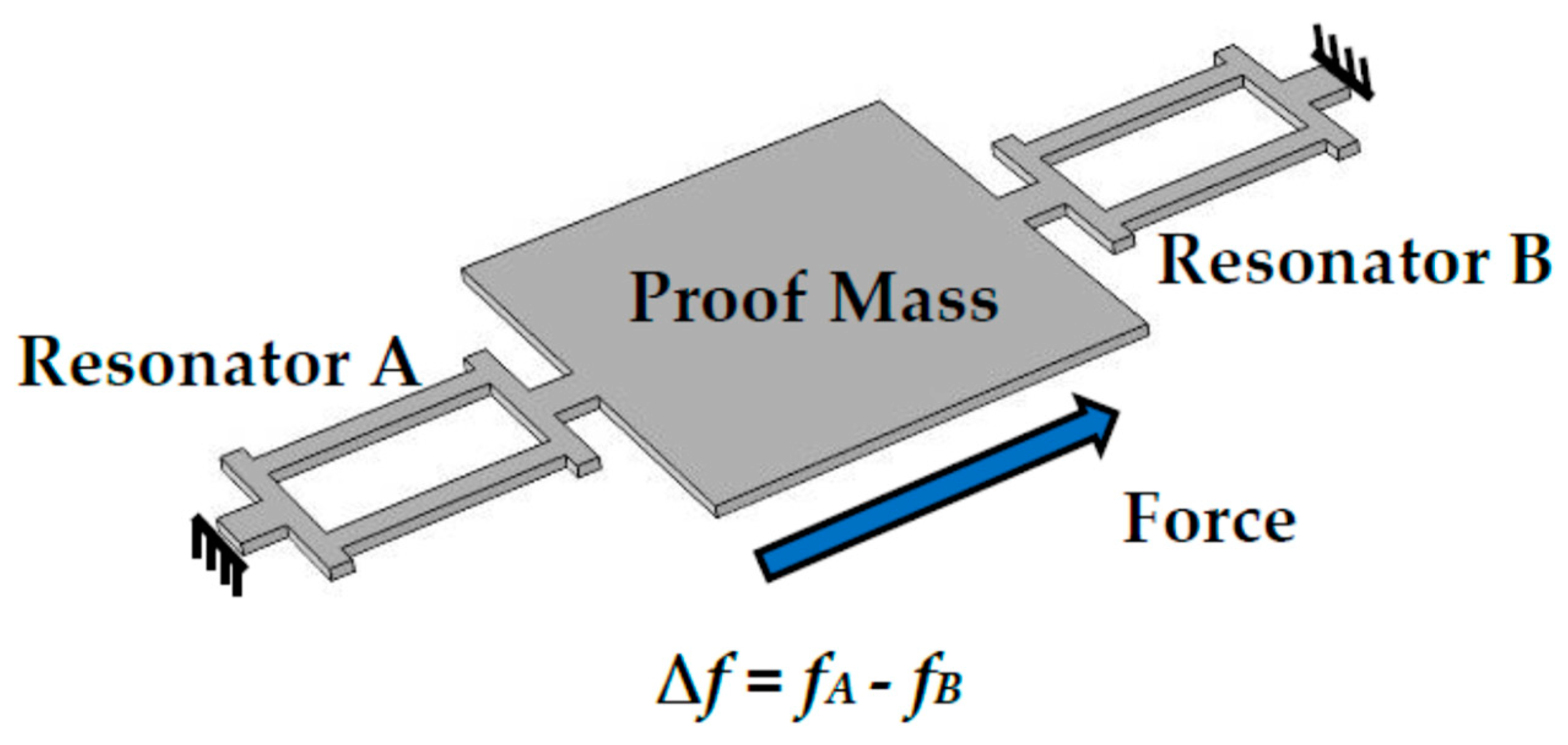
2. Design
3. Fabrication
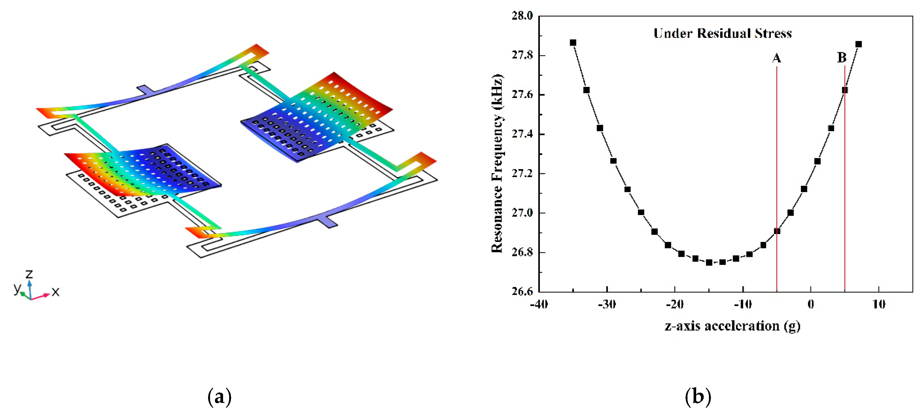
4. Results and Discussion
5. Conclusions
Author Contributions
Funding
Conflicts of Interest
References
- Wang, S.; Deng, Z.; Yin, G. An Accurate GPS-IMU/DR Data Fusion Method for Driverless Car Based on a Set of Predictive Models and Grid Constraints. Sensors 2016, 16, 280. [Google Scholar] [CrossRef]
- Zhao, Y.L.; Li, X.B.; Liang, J.; Jiang, Z.D. Design, fabrication and experiment of a MEMS piezoresistive high-g accelerometer. J. Mech. Sci. Technol. 2013, 27, 831–836. [Google Scholar] [CrossRef]
- Zhao, H.F.; Ren, W.; Liu, X.S. Design and fabrication of micromachined pyroelectric infrared detector array using lead titanate zirconate (PZT) thin film. Ceram. Int. 2017, 43, S464–S469. [Google Scholar] [CrossRef]
- Cooper, E.B.; Post, E.R.; Griffith, S.; Levitan, J.; Manalis, S.R.; Schmidt, M.A.; Quate, C.F. High-resolution micromachined interferometric accelerometer. Appl. Phys. Lett. 2000, 76, 3316–3318. [Google Scholar] [CrossRef]
- Yamane, D.; Konishi, T.; Matsushima, T.; Machida, K.; Toshiyoshi, H.; Masu, K. Design of sub-1g microelectromechanical systems accelerometers. Appl. Phys. Lett. 2014, 104, 074102. [Google Scholar] [CrossRef]
- Chao, M.Y.; Ali, A.; Ghosh, S.; Lee, J.E.Y. An Aluminum Nitride on Silicon resonant MEMS accelerometer operating in ambient pressure. In Proceedings of the 19th International Conference on Solid-State Sensors, Actuators and Microsystems (TRANSDUCERS), Kaohsiung, Taiwan, 18–22 June 2017; pp. 607–610. [Google Scholar]
- Wang, Y.; Ding, H.; Le, X.; Wang, W.; Xie, J.A. MEMS piezoelectric in-plane resonant accelerometer based on aluminum nitride with two-stage microleverage mechanism. Sens. Actuators, A 2017, 254, 126–133. [Google Scholar] [CrossRef]
- Vigevani, G. MEMS Aluminum Nitride Technology for Inertial Sensors. Ph.D. Thesis, University of California, Berkeley, CA, USA, 2011. [Google Scholar]
- Bao, F.H.; Bao, L.L.; Li, X.Y.; Khan, M.A.; Wu, H.Y.; Qin, F. Multi-stage phononic crystal structure for anchor-loss reduction of thin-film piezoelectric-on-silicon microelectromechanical-system resonator. Appl. Phys. Express 2018, 11, 067201. [Google Scholar] [CrossRef]
- Manzaneque, T.; Hernando-García, J.; Ababneh, A.; Schwarz, P.; Seidel, H.; Schmid, U. Quality-factor amplification in piezoelectric MEMS resonators applying an all-electrical feedback loop. J. Micromech. Microeng. 2011, 21, 025007. [Google Scholar] [CrossRef]
- Ruiz-Díez, V.; Manzaneque, T.; Hernando-García, J.; Ababneh, A.; Kucera, M.; Schmid, U. Design and characterization of AlN-based in-plane microplate resonators. J. Micromech. Microeng. 2013, 23, 074003. [Google Scholar] [CrossRef]
- Ruiz-Díez, V.; Hernando-García, J.; Toledo, J.; Manzaneque, T.; Kucera, M.; Pfusterschmied, G. Modelling and characterization of the roof tile-shaped modes of AlN-based cantilever resonators in liquid media. J. Micromech. Microeng. 2016, 26, 084008. [Google Scholar] [CrossRef]
- OlssonIII, R.H.; Wojciechowski, K.E.; Baker, M.S.; Tuck, M.R.; Fleming, J.G. Post-CMOS-Compatible Aluminum Nitride Resonant MEMS Accelerometers. J. Microelectromech. Syst. 2009, 18, 671–678. [Google Scholar] [CrossRef]
- Vigevani, G.; Goericke, F.T.; Pisano, A.P.; Izyumin, I.I.; Boser, B.E. Microleverage DETF Aluminum Nitride resonating accelerometer. In Proceedings of the 2012 IEEE International Frequency Control Symposium Proceedings, Baltimore, MD, USA, 21–24 May 2012; pp. 1–4. [Google Scholar]
- Yang, J.; Zhang, M.; Si, C.; Han, G.; Ning, J.; Yang, F.; Wang, X. A T-Shape Aluminum Nitride Thin-Film Piezoelectric MEMS Resonant Accelerometer. J. Microelectromech. Syst. 2019, 1–6. [Google Scholar] [CrossRef]
- Sharma, A.; Zaman, F.M.; Amini, B.V.; Ayazi, F. A high-Q in-plane SOI tuning fork gyroscope. In Proceedings of the Sensors 2004 Proceedings of IEEE, Vienna, Austria, 24–27 October 2004; pp. 467–470. [Google Scholar]
- Hernando, J.; Sanchez-Rojas, J.L.; Gonzalez-Castilla, S.; Iborra, E.; Ababneh, A.; Schmid, U. Simulation and laser vibrometry characterization of piezoelectric AIN thin films. J. Appl. Phys. 2008, 104, 053502. [Google Scholar] [CrossRef]
- Martin, F.; Muralt, P.; Dubois, M.-A.; Pezous, A. Thickness dependence of the properties of highly c-axis textured AlN thin films. J. Vac. Sci. Technol. A 2004, 22, 361–365. [Google Scholar] [CrossRef]
- Yang, J.; Si, C.; Yang, F.; Han, G.; Ning, J.; Yang, F. Design and Simulation of A Novel Piezoelectric AlN-Si Cantilever Gyroscope. Micromachines 2018, 9, 81. [Google Scholar] [CrossRef]
- Gil, M.; Manzaneque, T.; Hernando-García, J.; Ababneh, A.; Seidel, H.; Sanchez-Rojas, J.L. Multimodal characterisation of high-Q piezoelectric micro-tuning forks. IET Circuits Devices Syst. 2013, 7, 361–367. [Google Scholar] [CrossRef]
- Zhang, M.; Yang, J.; Si, C.W.; Han, G.W.; Zhao, Y.M.; Ning, J. Research on the Piezoelectric Properties of AlN Thin Films for MEMS Applications. Micromachines 2015, 6, 1236–1248. [Google Scholar] [CrossRef]
- Yang, J.; Si, C.W.; Han, G.W.; Zhang, M.; Ma, L.H.; Zhao, Y.M. Researching the Aluminum Nitride Etching Process for Application in MEMS Resonators. Micromachines 2015, 6, 281–290. [Google Scholar] [CrossRef]


| Parameters | Dimensions |
|---|---|
| Length of the beam (AB) | 1150 μm |
| Width of the beam (AB) | 35 μm |
| Length of the beam (CD) | 400 μm |
| Width of the beam (CD) | 25 μm |
| Width of the electrodes | 12 μm |
| The sides of the proof mass | 500 μm |
| The sides of the releasing hole | 20 μm |
| The thickness of the structure | 2.05 μm |
| Parameters | AlN | Mo | SiO2 | Si | Pt | Ti |
|---|---|---|---|---|---|---|
| Density (kg/m3) | 3300 | 10,200 | 2200 | 2329 | 21,450 | 4506 |
| Young’s Modulus (GPa) | 410 | 312 | 70 | 170 | 168 | 115 |
© 2019 by the authors. Licensee MDPI, Basel, Switzerland. This article is an open access article distributed under the terms and conditions of the Creative Commons Attribution (CC BY) license (http://creativecommons.org/licenses/by/4.0/).
Share and Cite
Yang, J.; Zhang, M.; He, Y.; Su, Y.; Han, G.; Si, C.; Ning, J.; Yang, F.; Wang, X. A Resonant Z-Axis Aluminum Nitride Thin-Film Piezoelectric MEMS Accelerometer. Micromachines 2019, 10, 589. https://doi.org/10.3390/mi10090589
Yang J, Zhang M, He Y, Su Y, Han G, Si C, Ning J, Yang F, Wang X. A Resonant Z-Axis Aluminum Nitride Thin-Film Piezoelectric MEMS Accelerometer. Micromachines. 2019; 10(9):589. https://doi.org/10.3390/mi10090589
Chicago/Turabian StyleYang, Jian, Meng Zhang, Yurong He, Yan Su, Guowei Han, Chaowei Si, Jin Ning, Fuhua Yang, and Xiaodong Wang. 2019. "A Resonant Z-Axis Aluminum Nitride Thin-Film Piezoelectric MEMS Accelerometer" Micromachines 10, no. 9: 589. https://doi.org/10.3390/mi10090589
APA StyleYang, J., Zhang, M., He, Y., Su, Y., Han, G., Si, C., Ning, J., Yang, F., & Wang, X. (2019). A Resonant Z-Axis Aluminum Nitride Thin-Film Piezoelectric MEMS Accelerometer. Micromachines, 10(9), 589. https://doi.org/10.3390/mi10090589