Article

Polarized Light Pollution of Fixed-Tilt Photovoltaic Solar Panels Measured by Drone-Polarimetry and Its Visual-Ecological Importance

1
Environmental Optics Laboratory, Department of Biological Physics, ELTE Eötvös Loránd University, Pázmány Sétány 1, H-1117 Budapest, Hungary
2
Drem Innovation and Consulting Ltd., Szentendrei út 95, H-1033 Budapest, Hungary
*
Author to whom correspondence should be addressed.
Remote Sens. 2024, 16(7), 1177; https://doi.org/10.3390/rs16071177
Submission received: 8 February 2024 / Revised: 23 March 2024 / Accepted: 25 March 2024 / Published: 28 March 2024
(This article belongs to the Special Issue Drone Remote Sensing II)

Abstract

:
Specific polarized light pollution (PLP) means the adverse influences of strongly and horizontally polarized light reflected from smooth and dark artificial surfaces on polarotactic water-seeking aquatic insects. Typical PLP sources are photovoltaic panels. Using drone-based imaging polarimetry, in a solar panel farm, we measured the reflection-polarization patterns of fixed-tilt photovoltaic panels from the viewpoint of flying polarotactic aquatic insects, which are the most endangered targets and potential victims of such panels. We found that the temporal changes in PLP were complementary for the two orthogonal viewing directions relative to the panel rows. The estimated magnitude plp of the polarized light pollution of solar panels viewed parallel to the panel rows was the highest (primary peak plp = 49–58% after sunrise and secondary peak plp = 35–48% prior to sunset) at low solar elevations, after sunrise and at or prior to sunset, when many aquatic insect species fly and seek water bodies. On the other hand, the PLP of solar panels viewed perpendicular to the panel rows was the highest (plp = 29–35%) at the largest solar elevations, near noon, when numerous flying aquatic insect species also seek water. Solar panel farms near wetlands can, therefore, be dangerous for these insects.

1. Introduction

Artificial night lights radiated from the Earth’s surface upward into the Universe are scattered back toward the surface by the atmosphere (molecules and aerosols) [1]. This backscattered light overwhelms the faint light of many celestial objects (planets, stars, galaxies, nebulaes) with small radiance. This phenomenon, called astronomical light pollution, makes it very difficult to make all ground-based astronomical observations. Under ecological light pollution, all adverse effects of artificial nocturnal lights on animals and humans are meant [2,3]. A special form of ecological light pollution is polarized light pollution (PLP): in a wider sense, PLP means the harmful effects of artificial polarized day or night lights on polarization-sensitive animals. In a narrower sense, the experimentally well-corroborated and thoroughly studied PLP involves only the adverse influences of strongly (i.e., with high degrees of linear polarization d) and nearly horizontally (i.e., with angles of polarization α ≈ 90° relative to the vertical) polarized light reflected from smooth and dark man-made surfaces on polarotactic water-loving insects [4]. Since all published case studies belong to this narrow-sense type, in this work, we deal only with it, which is called specific PLP further on in this work. d is the portion of the total light intensity I with an electric field vector oscillating in a dominating plane, the orientation of which is called the angle α of polarization. The partially linearly polarized light of a given wavelength (colour) is characterized by variables I, d and α.
As aquatic insects detect water bodies predominantly by perceiving the horizontally polarized light reflected from water surfaces [5], they are attracted to such light. Horizontally polarizing artificial surfaces deceive these insects that land and often lay their eggs on them [6]. Since the oviposited eggs irremediably perish due to dehydration [7], this phenomenon can endanger the local insect population concerned. Therefore, in the last few decades, researchers have thoroughly mapped the sources of PLP in order to understand the hazards with which aquatic insects are confronted in their optical environment [8,9,10,11].
In practice, all shiny (i.e., smooth) and dark (especially horizontal black) artificial surfaces can be sources of specific PLP, the two prerequisites of which are that the degree of polarization d is larger than the threshold d* of polarization sensitivity of the concerned aquatic insect (i.e., d > d*) and the angle of polarization α (measured from the vertical) of reflected light is approximately horizontal, that is, it deviates from the horizontal less than the threshold angle α* (i.e., |90° − α| < α*) [4]. Since the reflected light is always perpendicularly polarized to the plane of reflection (determined by the incident and reflected light rays), the second prerequisite is that the reflection plane is nearly vertical. Typical PLP sources are asphalt roads [7], dark car bodies [12], dark glass surfaces [13], black plastic sheets used in agriculture [14], crude oil spills [15], black gravestones [16], etc.
The PLP associated with photovoltaic solar panels is of particular importance, because several studies have indicated that these panels can attract polarotactic aquatic insects to lay their eggs upon them [9,11]. Furthermore, the PLP of solar panels can be a possible indirect cause of bat-panel collisions [17,18]: the polarotactic insects attracted by the polarization of panel-reflected light can lure insectivorous bats [13], which consume these deceived insects. Photovoltaic use is expanding dramatically worldwide, and relatively little is known about their reflection-polarization characteristics. Since the tilt angle of certain photovoltaics can change (to maximize photon capture) or be fixed relative to the ground, the polarization properties of light reflected from them are difficult to predict and, thus, largely unknown.
The polarization of earthlight (i.e., light scattered and reflected upward from the Earth’s surface) can be measured via imaging polarimetry [19]. In remote sensing, various imaging polarimeters are used to obtain the reflection-polarization patterns of the Earth’s surface. Considering the height of such measurements, there are two main cathegories of polarimetry: near-pol-sensing happens from 1 to 1.5 m above the ground surface [20,21,22,23], while remote-pol-sensing is performed at large/huge heights from balloons (~3–5 km) [24,25,26], or satellites (~700–800 km) (POLDER = Polarization and Directionality of the Earth’s Reflectances: Deschamps et al. [27], while PARASOL = Polarization and Anisotropy of Reflectances for Atmospheric Sciences with Observations from a Lidar) [28]. Polarimetric studies from intermediate (10–100 m) heights were previously lacking. Nowadays, this intermediate pol-sensing can be optimally conducted from drones. Recently, Száz et al. [10] investigated the reflection-polarization characteristics of dark lake patches with drone-based imaging polarimetry.
In the past, the PLP sources have been quantified by near-pol-sensing from ground-borne imaging polarimeters (reviewed by [8]). Their advantage is their large spatial resolution, while their disadvantage is that they can only capture a small ground area. Although satellite-borne imaging polarimeters can efficiently scan a large area of the Earth’s surface [28,29], their spatial resolutions are not high enough to record the fine details of the reflection-polarization patterns of PLP sources. An intermediate solution is using drone-borne imaging polarimetry, which can scan a relatively large (medium) ground area with relatively high (moderate) resolution.
To fill in the gap between near- and remote-pol-sensing, that is, between ground- and satellite-borne imaging polarimetry, Száz et al. [10] developed a drone-based imaging polarimeter consisting of a drone equipped with a linear polarization camera. With this equipment, we measured the reflection-polarization characteristics of fixed-tilt photovoltaic solar panels from the viewpoint of flying polarotactic aquatic insects, which are the most endangered targets and potential victims of such panels. According to Száz et al. [9] and Fritz et al. [11], these photovoltaic solar farms offer relevant PLP for water-loving polarotactic insects. In this work, we present the reflection-polarization patterns and the temporal change in the polarized light pollution of solar panels measured from two orthogonal viewing directions between sunrise and sunset on a sunny and an overcast day, and we discuss their visual-ecological importance.

2. Materials and Methods

The drone-polarimetric measurements for a fixed-tilt photovoltaic solar panel farm (47°41’56”N, 19°9’49”E) between the villages Göd and Sződliget (Northern Hungary) were performed on a sunny day and an overcast day: on 30 June 2022, the sky was sunny all day, while on 24 August 2022, the sky was overcast, sometimes with fewer clouds. The tilt angle of the panels (Trina Solar monocrystalline, 450 W) from the horizontal was 33°, which is the energetically optimal value in Hungary. The measurements were conducted from sunrise to sunset in two-hourly sessions.
Using a light (weight w = 65 g) and small (volume v = 3 cm × 3 cm × 6 cm) linear polarization camera (Color GigE DYK 33GX250 Polarsens®, vendor: Basler, Ahrensburg, Germany; polarization-sensitive CMOS sensor: Sony’s Pregius STM IMX250MYR) installed on a drone (DJI Matrice 210 v2 RTK), a polarization image was captured every two seconds. The objective lens (type: Basler Lens C125-0418-5M-P-f4mm, vendor: Basler) of the camera has the diameter D = 29 mm, focal length f = 4 mm, and field of view δ = 86°. The sensitivity ranges of the RGB filters of this camera are as follows: red (650 ± 50 nm), green (550 ± 50 nm), and blue (450 ± 50 nm). The techniques dealing with aliasing due to the 4 × 4 superpixels in the channeled spatiotemporal polarization sensor systems (e.g., polarization-sensitive CMOS sensors) are described in the literature [30]. The studied solar panels did not have a bluish hue (characteristic for the silicon), possessed a protecting glass covering, and did not have an anti-reflective coating. Due to these features, they were shiny black to the human eye, and their reflection-polarization characteristics were practically independent of wavelength in the visible range of the spectrum in which the used CMOS sensor is sensitive. Thus, in this work, we present only the polarization characteristics measured in the green part of the spectrum. They were very similar in the red and blue spectral ranges.
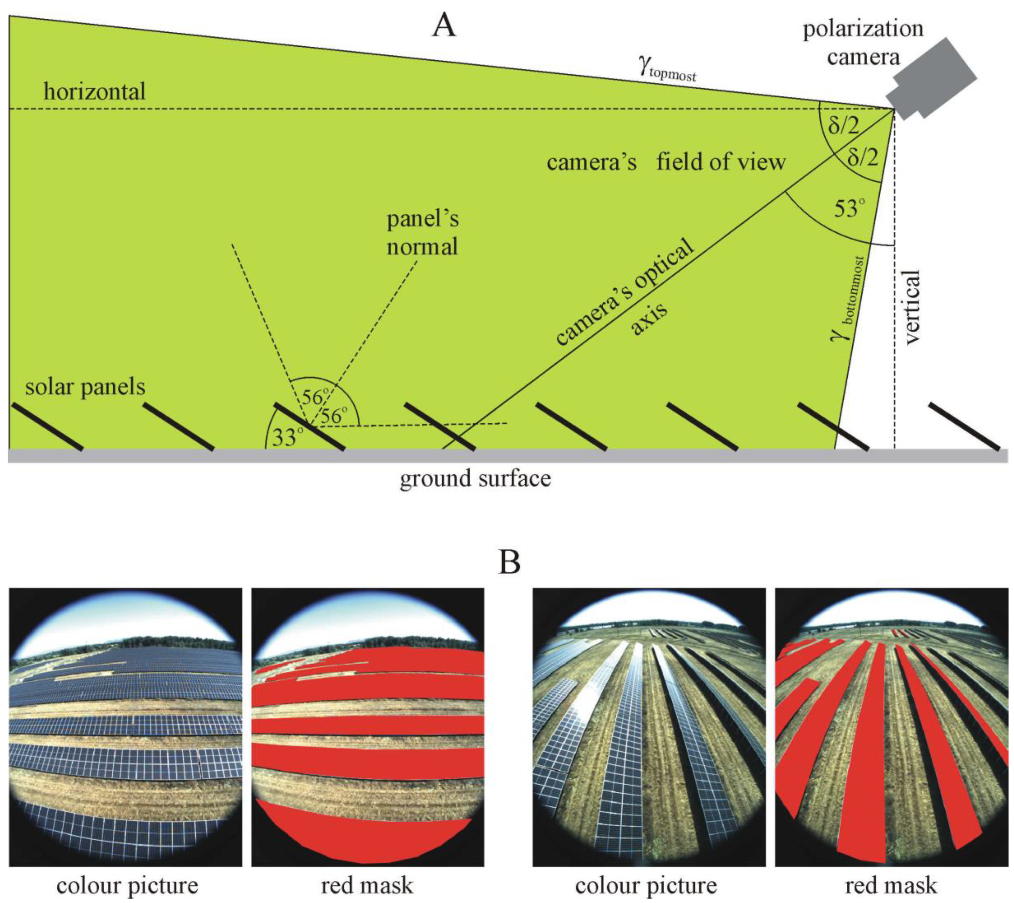
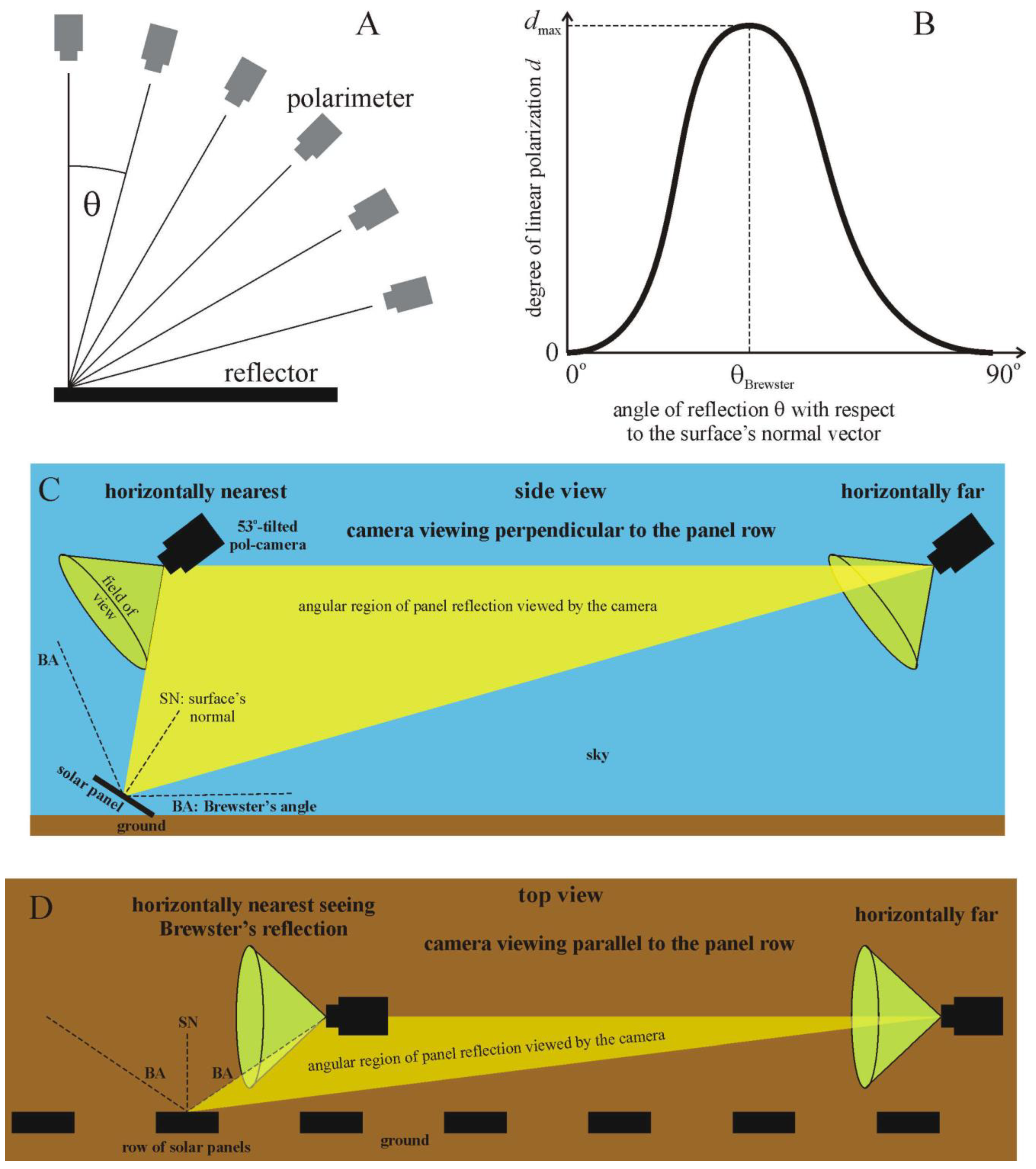
The camera was mounted on the bottom of the drone, and its optical axis pointed toward Brewster’s angle θBrewster = arctan (n = 1.33) = 53°, measured from the vertical, where n = 1.33 is the refractive index of water (Figure 1A). An angle of 53° was chosen, since water-seeking polarotactic aquatic insects predominantly detect water by means of the highly and horizontally polarized light mainly coming from this direction [6,31,32,33].
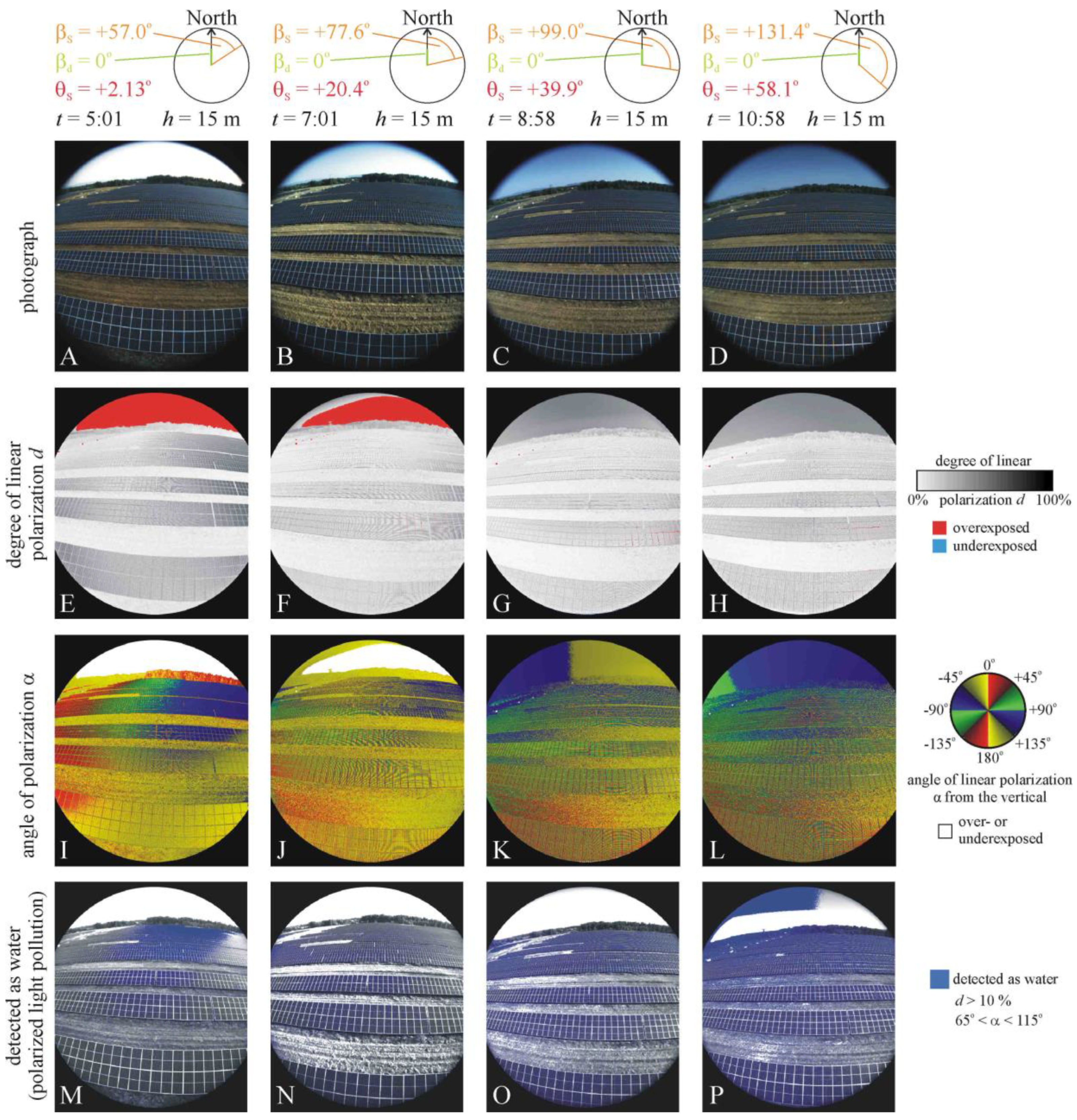
In our two measurement campaigns, we measured the reflection-polarization patterns of the fixed-tilt photovoltaic solar panels in two azimuth directions: perpendicular (Figure 2, 
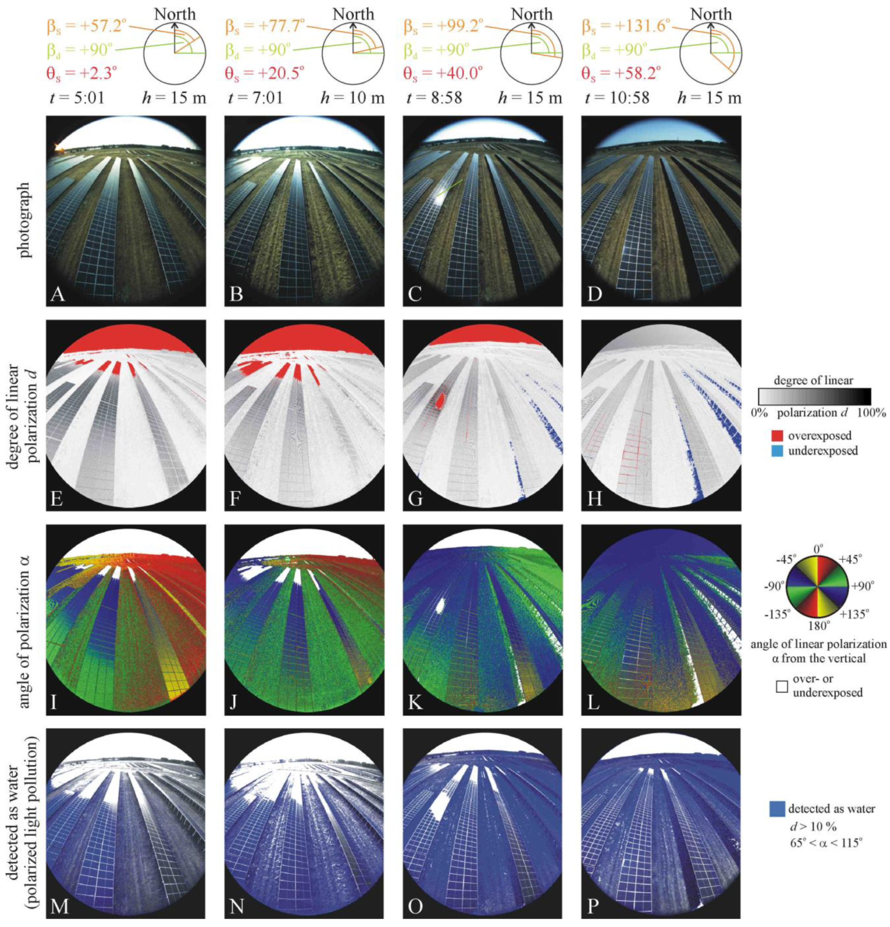
Supplementary Figures S1, S3 and S4) and parallel (Figure 3, Supplementary Figures S2, S5 and S6) to the rows of panels. These two viewing directions were enough to register the typical reflection-polarization characteristics of fixed-tilt solar panels. In this work, the sun-to-drone angle of the optical axis of the polarization camera measured from the solar meridian was marked by βd, while the azimuth angle of the Sun from the geographical North and the elevation angle of the Sun above the horizon were marked by βS and θS, respectively. Furthermore, d is the degree (%) of linear polarization, and α is the angle of polarization measured clockwise from the vertical. The definition of both polarization variables is available in [19], for example.
The polarization images taken by the drone-based linear polarization camera were evaluated using our custom-written software (Python programming language using the OpenCV algorithm package). According to our test of the polarization camera and the evaluation of its polarization images, the net uncertainties Δd and Δα of the measured degree of linear polarization d and angle of polarization α of light transmitted through a linearly polarizing sheet (P-ZN/R-12628, Schneider, Bad-Kreuznach, Germany) with different transmission directions (0°, 45°, 90°, 135° from the vertical) were Δd ≈ ±1% and Δα ≈ ±1° for d = 100% and Δd ≈ ±3% and Δα ≈ ±3° for d = 15% (the threshold of the polarization sensitivity of aquatic insects [33]). The possible error sources can be the photon-detection noise, induced polarization/cross-talk from the lens, differential pixel gains, aliasing, etc. We did not determine the individual contributions of these error sources to the net absolute error. The evaluation process for polarization images and further details of our drone-polarimetry were described by Száz et al. [10].
In this work, plp = Nwater/Npanel is the quantitative measure of the polarized light pollution of solar panels, where Nwater is the number of panel pixels detected as water by a polarotactic insect, and Npanel is the number of the whole panel area, the numbers of which were determined as follows: (1) We constructed a red mask (Figure 1B) containing all solar panels visible on the picture taken by the polarization camera from the drone. (2) From this red mask, the over- or underexposed pixels were removed, and our software counted the number Npanel of the remaining red pixels of the mask. (3) In the picture, we determined those pixels for which the conditions d > d* and |90° − α| < α* were satisfied, which represented the pixels that would be sensed as water by a hypothetical polarotactic aquatic insect possessing polarization sensitiviy thresholds d* and α*. These pixels are marked by blue colour in the last rows of Figure 2 and Figure 3 (and Supplementary Figures S1–S6). (4) The number Nwater of blue pixels (without any over- or underexposed pixels) of the areas detected as water was also counted. (5) Finally, the quotient plp = Nwater/Npanel was calculated.

3. Results

3.1. Spatiotemporal Change in Reflection-Polarization of Solar Panels

Figure 2 (and Supplementary Figure S1) shows the photographs, patterns of the degree of linear polarization d and angle of polarization α, and areas detected as water (for which the reflected light has the following polarization characteristics: d > 10% and 65° < α < 115°) of photovoltaic fixed-tilt solar panels measured on a two-hourly basis from sunrise (t = 5:01 = local summer time = UTC + 2 h) to sunset (t = 20:15) on the sunny day (30 June 2022) with drone-polarimetry in the green (550 nm) spectral range as a function of time (i.e., the azimuth angle βS and elevation angle θS of the Sun above the horizon) when the azimuth of the drone’s optical axis pointed toward North being perpendicular to the panel rows orienting East–West. Both the d and α of the panel-reflected light changed spatially with time, both vertically on a panel and horizontally along a panel row, due to the change in the angle of reflection of light entering the drone-based polarimeter. The highest d-values always occurred in directions from which light was exactly or nearly reflected from Brewster’s angle. In the d-patterns of Figure 2E–H (and Supplementary Figure S1F–J) in every panel row, the panel region with maximal d-values moved from the right side, toward the center and then to the left side of the scene from sunrise through noon to sunset. The largest panel areas with exactly or nearly horizontal polarization occurred at sunrise (Figure 2I), near noon (Figure 2L and Figure 3K) and at sunset (Supplementary Figure S1O). As a result of the spatiotemporally changing d- and α-values of panel-reflected light, the panel areas sensed as water (depicted by blue in the last rows of Figure 2 and Supplementary Figure S1) by a flying polarotactic aquatic insect approaching the solar farm perpendicular to the panel rows moved along the panel rows, as seen in Figure 2M–P (and Supplementary Figure S1P–T). According to Figure 2 (and Supplementary Figure S1 and Supplementary Table S1), the measure plp of polarized light pollution was maximal (plpmax = 28.94%) at 12:59, i.e., near noon, and minimal (plpmin = 7.50%) at 18:30 on the sunny day when the drone’s optical axis was perpendicular to the panel rows.
Figure 3 (and Supplementary Figure S2) displays the photographs, d- and α-patterns and areas detected as water for the fixed-tilt solar panels measured on a two-hourly basis from sunrise (t = 5:01) to sunset (t = 20:15) on the sunny day (30 June 2022) in the green (550 nm) part of the spectrum when the azimuth of the drone’s optical axis was parallel to the panel rows. The d- and α-values of reflected light again changed spatiotemporally along all panel rows from sunrise through noon to sunset. The highest d-values occurred on the left panel rows at sunrise (Figure 3E) and on the middle panel rows at sunset (Supplementary Figure S2J). The largest panel areas with exactly or nearly horizontal polarization occurred in the morning (Figure 3I–L) and at sunset (Supplementary Figure S2O). The panel areas sensed as water by polarotactic aquatic insects approaching the solar farm parallel to the panel rows again moved along the rows. According to Figure 3M–P (and Supplementary Figure S2P–T and Supplementary Table S1), the measure plp of polarized light pollution was maximal (plpmax = 58.46%) at 7:01, near sunrise, and minimal (plpmin = 25.98%) at 20:15, near sunset, when the drone’s optical axis was parallel to the panel rows.
On the overcast day (24 August 2022), when the azimuth of the drone’s optical axis was perpendicular to the panel rows (Supplementary Figures S3 and S4), the temporal changes in both the d- and α-patterns of solar panels were only moderate and much smaller than on the sunny day with a sunny sky (Figure 2, Supplementary Figure S1). The largest panel areas with exactly or nearly horizontal polarization occurred in the upper half and the center of the scene throughout the day (Supplementary Figures S3I–L and S4I–L). The areas sensed as water by polarotactic aquatic insects flying perpendicular to the panel rows were restricted to the central panels of the farthest and/or the middle panel rows. The measure plp of polarized light pollution of solar panels was maximal (plpmax = 34.57%) at 12:06, near noon, and minimal (plpmin = 12.13%) at 19:34, at sunset, when the azimuth of the drone’s optical axis was perpendicular to the panel rows (Supplementary Figures S3M–P and S4M–P and Supplementary Table S2).
Compared to the sunny day (Figure 3 and Supplementary Figure S2), on the overcast day (Supplementary Figures S5 and S6), the temporal variations in the d- and α-patterns of solar panels were again moderate and much smaller throughout the day. The degrees of polarization d of panel-reflected light were maximal near sunrise (Supplementary Figure S5E,F) and at sunset (Supplementary Figure S6H). The majority of solar panels reflected light with a polarization direction deviating from the horizontal by angles less than ±45° depicted with green and blue colours in the α-patterns. The areas sensed as water by polarotactic aquatic insects flying parallel to the panel rows were mainly restricted to the middle and lower panels of the left panel rows. The measure plp of polarized light pollution of solar panels was maximal (plpmax = 49.15%) at 8:08, near sunrise, and minimal (plpmin = 29.56%) at 14:12, at noon, when the azimuth of the drone’s optical axis was parallel to the panel rows (Supplementary Figures S5M–P and S6M–P, Supplementary Table S2).

3.2. Temporal Variations in Polarized Light Pollution of Solar Panels

Figure 4 shows the measure plp (%) of polarized light pollution of the studied solar panels versus time t (local summer time = UTC + 2 h) from sunrise to sunset on the sunny day (30 June 2022) and the overcast day (24 August 2022), when the drone-polarimeter’s azimuth was perpendicular (pointing toward North) and parallel (pointing toward East) to the solar panel rows. According to Figure 4A, on the sunny day, when the plp of solar panels viewed parallel to the panel rows was maximal (primary peak after sunrise and secondary peak prior to sunset), while the plp of panels viewed perpendicular to the panel rows was minimal. Hence, the temporal changes in plp were complementary for the two orthogonal viewing directions relative to the panel rows. Furthermore, viewing parallel to the panel rows, the plp was always larger than perpendicular in this direction, especially in the early morning and late afternoon. Near noon (13:00–15:00), the difference in plp between the two orthogonal viewing directions was minimal (Figure 4A).
The temporal behavior of plp on the overcast day (Figure 4B) was qualitatively very similar to that on the sunny day (Figure 4A): the temporal changes in plp were again complementary for the two orthogonal viewing directions relative to the panel rows; near noon (12:00–14:00), the differences in plp between these two directions were practically zero; and when viewed parallel to the panel rows, the plp was almost always larger than perpendicular in this direction, especially in the early morning and at sunset (Figure 4B).

4. Discussion

This work has the following three novelties: (i) Our drone-polarimetric method is new. Its first application was by Száz et al. [10], who measured the reflection-polarization characteristics of dark lake patches and explained their ecological implications. The present paper deals with the results of the second application of drone-polarimetry. (ii) The reflection-polarization patterns of a fixed-tilt photovoltaic solar farm and the quantity plp (%) of the polarized light pollution of solar panels derived from these patterns are measured for the first time by us using drone-based imaging polarimetry. (iii) The measured reflection-polarization characteristics of the studied photovoltaic farm are discussed from the point of view of flying polarotactic aquatic insects, which are the most endangered victims of polarized light pollution.
The ecological monitoring of changes in the concerned aquatic insect populations can start only after the monitoring of the polarized light pollution of photovoltaic solar farms. In this work, we present the results of the polarimetric monitoring of a Hungarian solar farm performed by drone-polarimetry. Here, we call the attention of ecologists to the importance of the future monitoring of the influence of solar farms on the local aquatic insect fauna.
The polarized light pollution (PLP) of smooth (shiny) and dark (especially black) artificial surfaces can be reduced or eliminated in the following ways [4,8]: (i) Making the surface rough (matt) results in it reflecting light diffusely with all possible angles of polarization α, the consequence of which is the considerable decrease in the net degree of linear polarization d of reflected light. The rougher (matter) the surface, the lower the d. Photovoltaic solar panels and other black reflectors with rough cover surface can have quite small PLP, but the reduction in PLP depends on both the surface mattness and the species of polarotactic aquatic insects concerned [9,11]. (ii) According to Umow’s law [34], darker surfaces reflect light with lower degrees of linear polarization d. Thus, upon making a polarized-light-polluting surface bright (especially white), its reflected d significantly drops, and, thus, its PLP drastically decreases [4]. (iii) If a shiny black surface is covered by a grid of thin white orthogonal or parallel lines, its PLP is reduced. The denser these white lines, the lower the PLP [8].
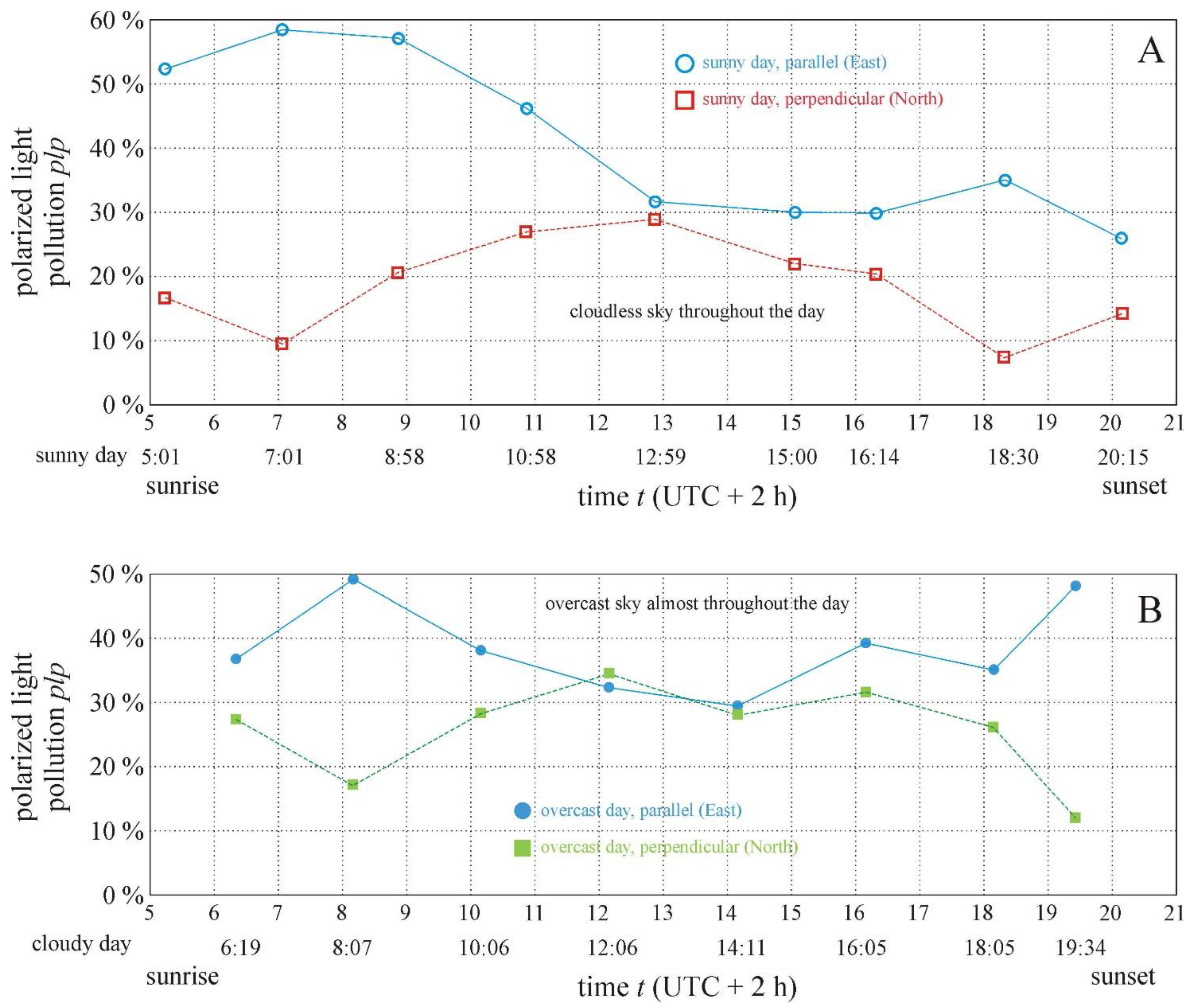
As seen by a water-seeking flying polarotactic aquatic insect, larger or smaller parts of an extended farm of tilted solar panels can be more or less polarized-light-polluting practically at any time in any viewing direction for any solar elevation depending on the angle of reflection φ (Figure 2, Figure 3 and Figure 4, Supplementary Figures S1–S6, Supplementary Tables S1 and S2). The nearer the φ is to Brewster’s angle θBrewster ≈ 53° relative to the normal vector of the solar panel, the larger the measure plp of polarized light pollution of the panel. Depending on the viewing direction (parallel or perpendicular to the solar panel rows), the plp is the highest at low (after sunrise and before sunset) or high solar elevations on both cloudless and cloudy days (Figure 4 and Supplementary Tables S1 and S2). This is a visually and ecologically important finding, because flying dispersing polarotactic aquatic insects predominantly seek water bodies at low and/or high solar elevations, that is, near morning, noon and/or evening, when polarotactic water detection is the most efficient [33]. Near noon, the plp of tilted solar panels is moderate (Figure 4 and Supplementary Tables S1 and S2); thus, aquatic insects flying mainly at high solar elevations (around noon) are less endangered by polarized light pollution than insects flying exclusively or mainly at low solar elevations (near sunrise and/or sunset) when the plp of tilted solar panels is much larger.
The solar panels investigated by us are black and smooth, thus possessing high PLP, which is, however, decreased, because they have a white orthogonal grid pattern due to construction/technical constraints. This PLP-decreasing grid effect is not taken into consideration in the calculation of the plp-value, as described in the Section 2.
In our study, we focused only on the tilted photovoltaic solar panels, while we ignored the sky and the grassy ground also seen in the pictures and polarization patterns taken by the drone-based polarization camera. Although in Figure 2P (and Supplementary Figures S1P, S2P–R and S3P), certain regions of the sky were recognized as water by our software, these celestial regions are, of course, irrelevant for water-seeking polarotactic insects, which detect the horizontally polarized signal reflected from water surfaces with the polarization-sensitive ventral regions of their compound eyes [5,6,31,32,33]. Similarly, our software recognized certain areas of the dry grassy ground in the last row of Figure 2 and Figure 3 (and Supplementary Figures S1–S6) as water (depicted by blue). The simple reason for both (sky and ground) misrecognitions is that our software considers all areas as water if the conditions d > 10% and 65° < α < 115° are satisfied. However, the grassy ground areas misrecognized as water do not attract polarotactic aquatic insects at all, because the scatter of the averagely horizontal polarization is large due to the ground/grass roughness, and large scatters of the angle of polarization repel these insects [8]. On the other hand, since these water-imitating spotty (composed of random dots) ground regions usually do not compose continuously connected horizontally polarizing larger areas, they do not attract water-seeking insects, which ignore too small spots/patches, even if they reflect horizontally polarized light [8]. The ecological reason for this ignorance is that a tiny water body with a surface area smaller than the insect-species-dependent threshold value is inappropriate for the development of larvae laid into the water. Too small water areas can drain out and/or warm up quickly, contain too little food and/or oxygen, contain too many predators, etc. Hence, a regular grass field or rough ground surface never attracts polarotactic water insects.
The interference between the intrinsic pixel grid of the polarization-sensitive CMOS sensor of our polarization camera and the grid structure of the surface of the studied solar panels resulted in the typical Moire’s pattern in certain parts of the polarization patterns in Figure 2 and Figure 3 (and Supplementary Figures S1–S6). Unfortunately, presently, this Moire’s artefact can be neither technically, nor computationally eliminated.
A similar disadvantage is that certain overly bright areas of the solar panels mirroring overly intense sky/sunlight are unavoidably overexposed. Since the polarizing characteristics of these overexposed areas are unknown, we ignored them during our computations. Certain overly dark areas of the scene in shadow were underexposed. Since these shadowed areas were always on the ground rather than on the solar panels, they did not cause problems in our investigations.
Figure 5A demonstrates how the degree d and angle α of the polarization of a horizontal solar panel can be measured using a polarimeter as a function of the angle θ of reflection from the surface’s normal vector, i.e., the vertical. After such a measurement, we can obtain the curve d(θ) that is shown qualitatively in Figure 5B: d is zero at θ = 0° and 90° and maximal at Brewster’s angle θBreswster = arctan (n), where n is the refractive index of the panel’s cover layer, which is typically nsolar panel ≈ 1.5 (for green light); thus, θ Brewster solar   panel 56.3 o . In the case of the water surface with nwater surface ≈ 1.33 (for green light), Brewster’s angle is θ Brewster water   surface 53.1 o .
In the studied photovoltaic solar farm, there were several thousand southward-facing fixed-tilt solar panels with a 33° tilt angle. The aim of our drone-polarimetry was not to simply measure the reflection-polarization characteristics (i.e., d and α) of an individual solar panel, because this could have been conducted much more simply with a horizontal panel (Figure 5A), the polarization features of which are well known (Figure 5B). Instead of this, our goal was to demonstrate the merit of drone-polarimetry, which is able to gather a huge amount of polarization information from a large area of the Earth’s surface falling within the wide field of view of the drone-based polarization camera. For this demonstration, we selected the mentioned photovoltaic farm as the target object and determined the net plp-values of polarized light pollution of all panels within the camera’s field of view to be ecologically important quantities derived from the measured d- and α-patterns.
In principle, by changing the azimuth angle of the drone levitating at a constant height above the solar farm and varying the elevation angle of the camera’s optical axis (with the drone’s gimbal), we could have performed drone-polarimetric measurement for numerous directions of view. However, this would have been very time-consuming and result in too large an amount of polarization data, which would be very difficult to evaluate and publish. Thus, we decided to reduce the number of azimuth directions to only two orthogonal directions: perpendicular and parallel to the row of solar panels. Furthermore, we chose only a single elevation angle of the camera’s optical axis, namely 53° from the vertical, practically coinciding with θ Brewster water   surface 53.1 o , because polarotactic aquatic insects (main victims of specific PLP) detect water bodies predominantly through perception of the horizontally and maximally polarized light reflected from the water surface from θ Brewster water   surface 53.1 o .
Of course, we appreciate that due to the 33° panel tilt, the degree of polarization d of panel-reflected light was not maximal at about 53° from the vertical, as explained in Figure 5C, which displays the side view of the geometry of our drone-polarimetry when the polarization camera (tilted 53° from the vertical) viewed perpendicular to a row of photovoltaic solar panels. Due to the panel tilt, the reflection angle from a panel in the vertical plane containing the drone was relatively far from θ Brewster solar   panel 56.3 o measured from the panel’s normal, as demonstrated in Figure 5C by the yellow angular region of panel reflection viewed by the polarization camera. Only a horizontally quite far drone-polarimeter (as shown by the right polarimeter in Figure 5C) could receive the maximal d of light reflected from the panel at θ Brewster solar   panel 56.3 o . The polarimeters that were horizontally near to the panel could not perceive the Brewster-reflected light in their field of view, as demonstrated by the left polarimeter shown in Figure 5C.
Figure 5D shows the top view of the geometry of our drone-polarimetry when the polarization camera (tilted 53° from the vertical) viewed parallel to a row of solar panels. If the camera was horizontally far from the panel, the polarimeter could sense only panel reflections far from Brewster’s angle (right polarimeter in Figure 5D). Only polarimeters horizontally near to the panel could receive the Brewster-reflected light from the panel. Finally, according to 
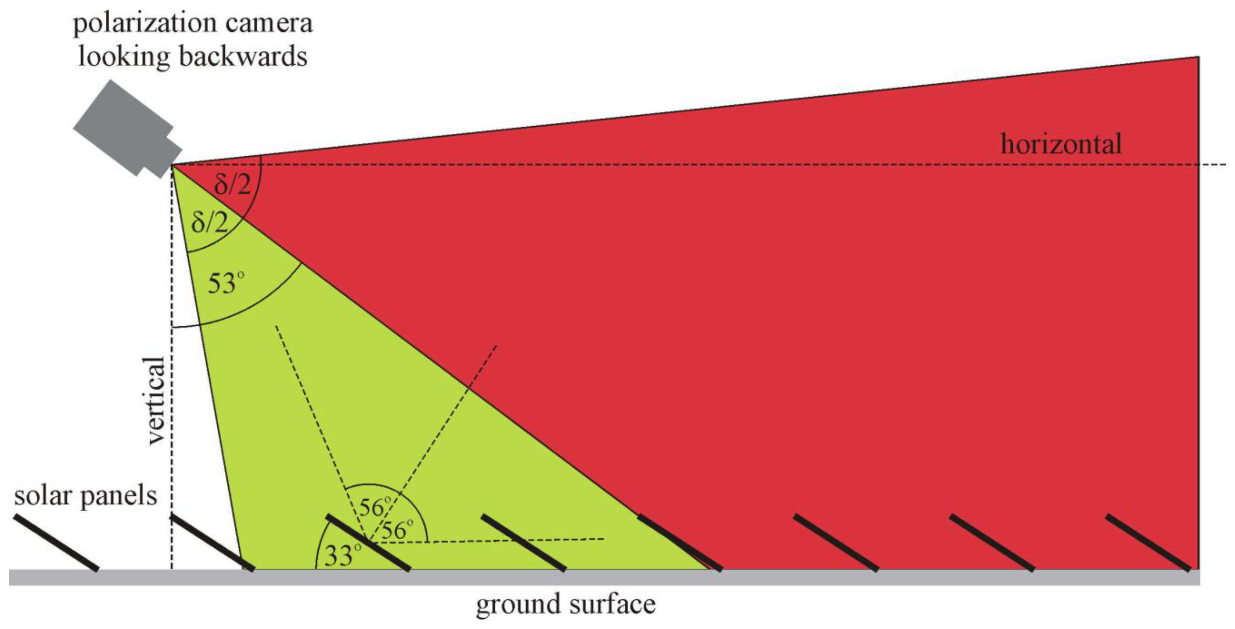
Figure 6, a polarization camera with a fixed-tilt angle θBrewster = 53° (from the vertical) looking backwards would be very disadvantageous, because in this case, the photovoltaic reflecting surface of the farther fixed-tilt solar panels could not be seen.
The consequence of the above was that our fixed-elevation drone-polarimeter saw only a few solar panels with Brewster’s reflection, which means that panel reflections were frequently above or below Brewster’s angle from the panel’s normal. Therefore, this approach underestimated the maximum degree of polarization that a polarotactic insect flying in the airspace above a solar farm can experience. This limitation could have been eliminated if the downward tilt of our polarization camera had been varied and the solar field had been resurveyed over and over the solar farm again with multiple passes, each at a different camera tilt. However, since this time-consuming task would have been very difficult to perform, we gave up on this complex approach.
Our drone-polarimetric technique was recently successfully used for the remote sensing of the reflection-polarization characteristics of dark lake patches and their ecological consequences [10]. Finally, we emphasize that our drone-polarimetric method is a valuable new tool that can be used for many different air-borne measurements beyond the quantification of polarized light pollution (PLP) in a biological context.
Although our study focused on the PLP of solar panels from the point of view of the concerned polarotactic aquatic insects, let us briefly consider its value to the solar farm owners. Wind-blown dust and other solid mineral particles originating from rain drops after their evaporation can aggregate on the panel surface. Beyond these contaminations, the eggs laid by aquatic insects deceived by and attracted to these panels, as well as the carcasses of these insects that died because of dehydration on the hot panels, reduce the panel’s light-absorbing efficiency. Therefore, the panel surfaces should be periodically cleaned, which is a time- and money-consuming task. Nowadays, drones are frequently used to monitor the cleanliness of photovoltaics. The use of drone-polarimetry can also be beneficial to assess the amount of contamination deposited on these panels. To reduce the high reflectivity of smooth and shiny photovoltaics, their surface is made matt (i.e., rough) by different anti-reflective coatings [9,11,35,36], enhancing the light-absorbing efficiency. In field experiments, it was shown that depending on the insect species, matt/rough solar panels can have much smaller PLP than shiny/smooth ones for polarotactic aquatic insects [9,11].
The PLP of photovoltaic panels is indirectly demonstrated by the more and more frequent observations of the number of panel collisions and the activity of insectivorous bats [13,17,18,37] at solar farms. The main reason for this is the enhanced number of insects deceived and lured by the horizontally polarized light reflected from solar panels.

5. Conclusions

On the basis of the results presented in this work, we draw the following conclusions: In a photovoltaic solar farm, there are always solar panels that are polarized-light-polluting and, therefore, attract flying water-seeking polarotactic aquatic insects independently of the solar elevation, sky cloudiness and viewing direction. From some viewing directions, these panels can reflect horizontally polarized light with a high enough degree of linear polarization and, thus, mimic the appearance of the water surface; therefore, the visually deceived aquatic insects may land and oviposit on them. The landing is dangerous for the adult insects, because they can perish if the panel surface is too hot in sunshine, while the laid eggs inevitably die due to dehydration. These perished adults and eggs can be a serious loss for the local population of the concerned insect species.
According to our drone-polarimetry performed at a photovoltaic solar panel farm, the temporal changes in polarized light pollution were complementary for the two orthogonal viewing directions (parallel and perpendicular) relative to the panel rows. The estimated and more or less underestimated magnitude plp of the polarized light pollution of solar panels viewed parallel to the panel rows measured by drone-polarimetry was the highest (primary peak plp = 49–58% after sunrise, and secondary peak plp = 35–48% prior to sunset) at low solar elevations, after sunrise and at or prior to sunset, when many aquatic insect species fly and seek water bodies. On the other hand, the plp of solar panels viewed perpendicular to the panel rows was the highest (plp = 29–35%) at the largest solar elevations, near noon, when numerous flying aquatic insect species also seek water. That is why solar panel farms can be dangerous for the populations of aquatic insects if there is a wetland in their vicinity with abundant water-loving insects.
Inspired by the high polarized light pollution plp ≤ 58% of the studied smooth (shiny) photovoltaic solar panels, we suggest reducing the degree of linear polarization d of panel-reflected light by either covering the panel’s surface with gridding composed of orthogonal thin (1–2 mm) white stripes, or by using an anti-reflective, matt covering. Both methods can considerably reduce, or even eliminate, the polarized light pollution of smooth black reflectors [4,8,9,11].

Supplementary Materials

The following supporting information can be downloaded via this link: https://www.mdpi.com/article/10.3390/rs16071177/s1. This file contains the following: Supplementary Tables S1 and S2 and Supplementary Figures S1–S6. Supplementary Table S1: Polarized light pollution plp (%) of solar panels versus time t (local summer time = UTC + 2 h) from sunrise to sunset on the sunny day (30 June 2022) when the drone-polarimeter’s azimuth was perpendicular (pointing toward North) and parallel (pointing toward East) to the solar panel rows being parallel to East-West. Supplementary Table S2: Polarized light pollution plp (%) of solar panels versus time t (local summer time = UTC + 2 h) from sunrise to sunset on the overcast day (24 August 2022) when the drone-polarimeter’s azimuth was perpendicular (pointing toward North) and parallel (pointing toward East) to the solar panel rows being parallel to East-West. Supplementary Figure S1: Continuation of Figure 2. From noon to sunset: (A, F, K, P) t = 12:59, h = 15 m, βS = +190.41°, θS = +65.16°, βd = 0°. (B, G, L, Q) t = 15:00, h = 15 m, βS = +240.84°, θS = +52.98°, βd = 0°. (C, H, M, R) t = 16:14, h = 15 m, βS = +259.01°, θS = +41.41°, βd = 0°. (D, I, N, S) t = 18:30, h = 15 m, βS = +284.14°, θS = +18.7°, βd = +0°. (E, J, O, T) t = 20:15, h = 15 m, βS = +303.09°, θS = +1.98°, βd = +0°. Supplementary Figure S2: Continuation of Figure 3. From noon to sunset: (A, F, K, P) t = 12:59, h = 15 m, βS = +190.79°, θS = +65.14°, βd = +90°. (B, G, L, Q) t = 15:00, h = 15 m, βS = +241.01°, θS = +52.89°, βd = +90°. (C, H, M, R) t = 16:14, h = 15 m, βS = +259.16°, θS = +41.29°, βd = +90°. (D, I, N, S) t = 18:30, h = 15 m, βS = +284.25°, θS = +18.6°, βd = +90°. (E, J, O, T) t = 20:15, h = 15 m, βS = +303.22°, θS = +1.88°, βd = +90°. Supplementary Figure S3: As Supplementary Figure S1 measured on an overcast day (24 August 2022) when the azimuth of the drone’s optical axis was perpendicular to the panel rows. From sunrise to noon: (A, E, I, M) t = 6:19, h = 15 m, βS = +77.73°, θS = +3.88°, βd = +0°. (B, F, J, N) t = 8:07, h = 15 m, βS = +97.73°, θS = +21.94°, βd = +0°. (C, G, K, O) t = 10:06, h = 15 m, βS = +124.17°, θS = +40.42°, βd = +0°. (D, H, L, P) t = 12:06, h = 15 m, βS = +163.92°, θS = +52.39°, βd = +0°. Supplementary Figure S4: Continuation of Supplementary Figure S3. From noon to sunset: (A, E, I, M) t = 14:11, h = 15 m, βS = +213.32°, θS = +49.1°, βd = 0°. (B, F, J, N) t = 16:05, h = 15 m, βS = +245.73°, θS = +34.45°, βd = 0°. (C, G, K, O) t = 18:05, h = 15 m, βS = +270.04°, θS = +14.83°, βd = 0°. (D, H, L, P) t = 19:34, h = 15 m, βS = +286.27°, θS = +0.07°, βd = 0°. Supplementary Figure S5: As Supplementary Figure S3 when the azimuth of the drone’s optical axis was parallel to the panel rows. From sunrise to noon: (A, E, I, M) t = 6:20, h = 15 m, βS = +77.91°, θS = +4.05°, βd = +90°. (B, F, J, N) t = 8:08, h = 15 m, βS = +97.95°, θS = +22.12°, βd = +90°. (C, G, K, O) t = 10:07, h = 15 m, βS = +124.47°, θS = +40.58°, βd = +90°. (D, H, L, P) t = 12:05, h = 15 m, βS = +163.61°, θS = +52.36°, βd = +90°. Supplementary Figure S6: Continuation of Supplementary Figure S5. From noon to sunset: (A, E, I, M) t = 14:12, h = 15 m, βS = +213.63°, θS = +49.01°, βd = +90°. (B, F, J, N) t = 16:06, h = 15 m, βS = +245.96°, θS = +34.3°, βd = +90°. (C, G, K, O) t = 18:06, h = 15 m, βS = +270.21°, θS = +14.68°, βd = +90°. (D, H, L, P) t = 19:35, h = 15 m, βS = +286.43°, θS = -0.07°, βd = +90°.

Author Contributions

Substantial contributions to conception and design: P.T., D.S., B.B., I.P. and G.H.; Software development: P.T. and D.S.; Performing experiments and measurements: P.T., D.S., B.B. and G.H.; Data visualization: P.T., D.S. and G.H.; Data analysis and interpretation: P.T., D.S., I.P. and G.H.; Drafting the article and revising it critically: P.T., D.S. and G.H. All authors have read and agreed to the published version of the manuscript.

Funding

This study was funded by a KDP-2020-ELTE-1010099 fellowship/grant from the Hungarian National Research, Development and Innovation Office provided to Péter Takács, who received further financial support from the Doctoral School of the Physical Institute of the Eötvös Loránd University. Dénes Száz was supported by the Hungarian UNKP-21-4 New National Excellence Program of the Ministry for Innovation and Technology via the National Research, Development and Innovation Fund.

Data Availability Statement

All data underlying the results presented in this paper are available in this paper and its Electronic Supplementary Materials.

Acknowledgments

We thank Attila Székely (Mad Solar Ltd., Debrecen, Hungary, https://madsolar.hu/, accessed on 1 June 2022) for allowing our drone-polarimetric measurement campaigns at their photovoltaic solar farm between Göd and Sződliget, eastern Hungary. We are grateful to three anonymous reviewers for their valuable comments about earlier versions of this paper.

Conflicts of Interest

The authors declare no conflicts of interest. The funders had no role in the design of the study; the collection, analyses, or interpretation of data; the writing of the manuscript; or the decision to publish the results. Authors Péter Takács, Balázs Bernáth and István Pomozi were also employed by the company Drem Innovation and Consulting Ltd. (Budapest, Hungary). The remaining authors declare that the research was conducted in the absence of any commercial or financial relationships that could be construed as a potential conflict of interest.

References

  1. Falchi, R.; Cinzano, P.; Duriscoe, D.; Kyba, C.C.M.; Elvidge, C.D.; Baugh, K.; Portnov, B.A.; Rybnikova, N.A.; Furgoni, R. The new world atlas of artificial night sky brightness. Sci. Adv. 2016, 2, sciadv.1600377. [Google Scholar] [CrossRef] [PubMed]
  2. Longcore, T.; Rich, C. Ecological light pollution. Front. Ecol. Environ. 2004, 2, 191–198. [Google Scholar] [CrossRef]
  3. Rich, C.; Longcore, T. Ecological Consequences of Artificial Night Lighting; Island Press: Washington, DC, USA, 2006. [Google Scholar]
  4. Horváth, G.; Kriska, G.; Malik, P.; Robertson, B. Polarized light pollution: A new kind of ecological photopollution. Front. Ecol. Environ. 2009, 7, 317–325. [Google Scholar] [CrossRef]
  5. Schwind, R. A variety of insects are attracted to water by reflected polarized light. Naturwissenschaften 1989, 76, 377–378. [Google Scholar] [CrossRef]
  6. Schwind, R. Polarization vision in water insects and insects living on a moist substrate. J. Comp. Physiol. A 1991, 169, 531–540. [Google Scholar] [CrossRef]
  7. Kriska, G.; Horváth, G.; Andrikovics, S. Why do mayflies lay their eggs en masse on dry asphalt roads? Water-imitating polarized light reflected from asphalt attracts Ephemeroptera. J. Exp. Biol. 1998, 201, 2273–2286. [Google Scholar] [CrossRef] [PubMed]
  8. Horváth, G.; Kriska, G.; Robertson, B. Chapter 20. Anthropogenic polarization and polarized light pollution inducing polarized ecological traps. In Polarized Light and Polarization Vision in Animal Sciences; Horváth, G., Ed.; Springer: Berlin/Heidelberg, Germany, 2014; pp. 443–513. [Google Scholar]
  9. Száz, D.; Mihályi, D.; Farkas, A.; Egri, Á.; Barta, A.; Kriska, G.; Robertson, B.; Horváth, G. Polarized light pollution of matte solar panels: Anti-reflective photovoltaics reduce polarized light pollution but benefit only some aquatic insects. J. Insect Conserv. 2016, 20, 663–675. [Google Scholar] [CrossRef]
  10. Száz, D.; Takács, P.; Bernáth, B.; Kriska, G.; Barta, A.; Pomozi, I.; Horváth, G. Drone-based imaging polarimetry of dark lake patches from the viewpoint of flying polarotactic insects with ecological implication. Remote Sens. 2023, 15, 2797. [Google Scholar] [CrossRef]
  11. Fritz, B.; Horváth, G.; Hünig, R.; Pereszlényi, Á.; Egri, Á.; Guttmann, M.; Schneider, M.; Lemmer, U.; Kriska, G.; Gomard, G. Bioreplicated coatings for photovoltaic solar panels nearly eliminate light pollution that harms polarotactic insects. Public Libr. Sci. One 2020, 15, e0243296. [Google Scholar] [CrossRef]
  12. Kriska, G.; Csabai, Z.; Boda, P.; Malik, P.; Horváth, G. Why do red and dark-coloured cars lure aquatic insects? The attraction of water insects to car paintwork explained by reflection-polarization signals. Proc. R. Soc. B 2006, 273, 1667–1671. [Google Scholar] [CrossRef]
  13. Pereszlényi, Á.; Horváth, G.; Kriska, G. Atypical feeding of woodpeckers, crows and redstarts on mass-swarming Hydropsyche pellucidula caddisflies attracted to glass panes. Urban Ecosyst. 2017, 20, 1203–1207. [Google Scholar] [CrossRef]
  14. Bernáth, B.; Kriska, G.; Suhai, B.; Horváth, G. Wagtails (Aves: Motacillidae) as insect indicators on plastic sheets attracting polarotactic aquatic insects. Acta Zool. Acad. Sci. Hung. 2008, 54, 145–155. [Google Scholar]
  15. Horváth, G.; Zeil, J. Kuwait oil lakes as insect traps. Nature 1996, 379, 303–304. [Google Scholar] [CrossRef]
  16. Horváth, G.; Malik, P.; Kriska, G.; Wildermuth, H. Ecological traps for dragonflies in a cemetery: The attraction of Sympetrum species (Odonata: Libellulidae) by horizontally polarizing black gravestones. Freshw. Biol. 2007, 52, 1700–1709. [Google Scholar] [CrossRef]
  17. Szabadi, K.L.; Kurali, A.; Rahman, N.A.A.; Froidevaux, J.S.P.; Tinsley, E.; Jones, G.; Görföl, T.; Estók, P.; Zsebők, S. The use of solar farms by bats in mosaic landscapes: Implications for conservation. Glob. Ecol. Conserv. 2023, 44, e02481. [Google Scholar] [CrossRef]
  18. Tinsley, E.; Froidevaux, J.S.P.; Zsebők, S.; Szabadi, K.L.; Jones, G. Renewable energies and biodiversity: Impact of ground-mounted solar photovoltaic sites on bat activity. J. Appl. Ecol. 2023, 60, 1752–1762. [Google Scholar] [CrossRef]
  19. Kong, J.A. Polarimetric Remote Sensing; Elsevier: Amsterdam, The Nederland, 1990. [Google Scholar]
  20. Prosch, T.; Hennings, D.; Raschke, E. Video polarimetry: A new imaging technique in atmospheric science. Appl. Opt. 1983, 22, 1360–1363. [Google Scholar] [CrossRef]
  21. Cronin, T.W.; Shashar, N.; Wolff, L. Portable Imaging Polarimeters. In Proceedings of the 12th IAPR International Conference on Pattern Recognition, Jerusalem, Israel, 9–13 October 1994; pp. 606–609. [Google Scholar]
  22. Gál, J.; Horváth, G.; Meyer-Rochow, V.B. Measurement of the reflection-polarization pattern of the flat water surface under a clear sky at sunset. Remote Sens. Environ. 2001, 76, 103–111. [Google Scholar] [CrossRef]
  23. Barter, J.D.; Thompson, H.R., Jr.; Richardson, C.L. Visible-regime polarimetric imager: A fully polarimetric, real-time imaging system. Appl. Opt. 2003, 42, 1620–1628. [Google Scholar] [CrossRef]
  24. Herman, M.; Balois, J.Y.; Gonzalez, L.; Lecomte, P.; Lenoble, J.; Santer, R.; Verwaerde, C. Stratospheric aerosol observations from a balloon-borne polarimetric experiment. Appl. Opt. 1986, 25, 3573–3584. [Google Scholar] [CrossRef]
  25. Deuzé, J.L.; Devaux, C.; Herman, M.; Santer, R.; Balois, J.Y.; Gonzalez, L.; Lecomte, P.; Verwaerde, C. Photopolarimetric observations of aerosols and clouds from balloon. Remote Sens. Environ. 1989, 29, 93–109. [Google Scholar] [CrossRef]
  26. Horváth, G.; Bernáth, B.; Suhai, B.; Barta, A.; Wehner, R. First observation of the fourth neutral polarization point in the atmosphere. J. Opt. Soc. Am. A 2002, 19, 2085–2099. [Google Scholar] [CrossRef] [PubMed]
  27. Deschamps, P.Y.; Bréon, F.M.; Leroy, M.; Podaire, A.; Bricaud, A.; Buriez, J.C.; Seze, G. The POLDER mission: Instrument characteristics and scientific objectives. IEEE Trans. Geosci. Remote Sens. 1994, 32, 598–615. [Google Scholar] [CrossRef]
  28. Fougnie, B.; Bracco, G.; Lafrance, B.; Ruffel, C.; Hagolle, O.; Tinel, C. PARASOL in-flight calibration and performance. Appl. Opt. 2007, 46, 5435–5451. [Google Scholar] [CrossRef]
  29. Leroy, M.; Deuzé, J.L.; Bréon, F.M.; Hautecoeur, O.; Herman, M.; Buriez, J.C.; Tanré, D.; Bouffiés, S.; Chazette, P.; Roujean, J.L. Retrieval of atmospheric properties and surface bidirectional reflectances over land from POLDER/ADEOS. J. Geophys. Res. D 1997, 102, 17023–17037. [Google Scholar] [CrossRef]
  30. Vaughn, I.J.; Tyo, J.S. Spatio-temporal hybrid color-polarization channeled sensors. In Proceedings of the SPIE 11132, Polarization Science and Remote Sensing IX, 111320K, San Diego, CA, USA, 6 September 2019. [Google Scholar] [CrossRef]
  31. Schwind, R. A polarization-sensitive response of the flying water bug Notonecta glauca to UV light. J. Comp. Physiol. 1983, 150, 87–91. [Google Scholar] [CrossRef]
  32. Schwind, R. The plunge reaction of the backswimmer Notonecta glauca. J. Comp. Physiol. A 1984, 155, 319–321. [Google Scholar] [CrossRef]
  33. Horváth, G.; Csabai, Z. Chapter 5. Polarization vision of aquatic insects. In Polarized Light and Polarization Vision in Animal Sciences; Horváth, G., Ed.; Springer: Berlin/Heidelberg, Germany, 2014; pp. 113–145. [Google Scholar]
  34. Umow, N. Chromatische Depolarisation durch Lichtzerstreuung. Phys. Z. 1905, 6, 674–676. [Google Scholar]
  35. Dong, S.; Zhang, J.; Jiao, H.; Zhang, W.; Li, X.; Wang, Z.; Cheng, X. Nanopillars assisted multilayer antireflection coating for photovoltaics with multiple bandgaps. Appl. Phys. Lett. 2019, 115, 133106. [Google Scholar] [CrossRef]
  36. Huh, D.; Choi, H.J.; Byun, M.; Kim, K.; Lee, H. Long-term analysis of PV module with large-area patterned anti-reflective film. Renew. Energy 2019, 135, 525–528. [Google Scholar] [CrossRef]
  37. Barre, K.; Baudouin, A.; Froidevaux, J.S.P.; Chartendrault, V.; Kerbiriou, C. Insectivorous bats alter their flight and feeding behaviour at ground-mounted solar farms. J. Appl. Ecol. 2024, 61, 328–339. [Google Scholar] [CrossRef]
Figure 1. (A) The optical axis of the drone-based polarization camera with the angle δ = 86° (δ/2 = 43°) for its field of view (green) looks on the ground surface at 53° (Brewster’s angle θBrewster for water with a refractive index of 1.33) relative to the vertical. γtopmost = 53° + δ/2 = 96° and γbottommost = 53° − δ/2 = 10° from the vertical. Also, 56° = Brewster’s angle for the cover layer of photovoltaics with a typical refractive index of 1.5, and 33° = the optimal tilt angle of solar panels from the horizontal in Hungary. (B) Two examples of the colour picture of the solar panel rows taken by the camera and the red mask covering the panel areas.
Remotesensing 16 01177 g001
Figure 2. Photographs, patterns of the degree of linear polarization d and angle of polarization α (measured clockwise from the vertical), and areas (blue) detected as water (for which the reflected light had the following polarization characteristics: d > 10% and 65° < α < 115°) of a fixed-tilt photovoltaic solar panel farm (47°41’56”N, 19°9’49”E) between the villages Göd and Sződliget (Northern Hungary) measured from sunrise to sunset on a sunny day (30 June 2022) with drone-based imaging polarimetry from the height h in the green (550 nm) spectral range as a function of the azimuth angle βS and elevation angle θS of the Sun above the horizon when the azimuth of the drone’s optical axis was perpendicular to the panel rows. The uppermost circular insets display βS and the nearly constant azimuth angle βd of the drone’s optical axis clockwise from the geographical North. From sunrise to noon, (A,E,I,M) t = 5:01 (local summer time = UTC + 2 h), h = 15 m, βS = +57.03°, θS = +2.13° and βd = 0°. Moreover, (B,F,J,N) t = 7:01, h = 15 m, βS = +77.56°, θS = +20.38° and βd = 0°. Finally, (C,G,K,O) t = 8:58, h = 15 m, βS = +99.01°, θS = +39.88°, βd = 0°. (D,H,L,P) t = 0:58, h = 15 m, βS = +131.39°, θS = +58.14° and βd = 0°.
Remotesensing 16 01177 g002
Figure 3. As shown in Figure 2, the azimuth of the drone’s optical axis was parallel to the panel rows. From sunrise to noon, (A,E,I,M) t = 5:01, h = 15 m, βS = +57.21°, θS = +2.27° and βd = +90°. Also, (B,F,J,N) t = 7:01, h = 15 m, βS = +77.68°, θS = +20.49° and βd = +90°. Moreover, (C,G,K,O) t = 8:58, h = 15 m, βS = +99.18°, θS = +40.02° and βd = +90°. Finally, (D,H,L,P) t = 10:58, h = 15 m, βS = +131.57°, θS = +58.2°, βd = +90°.
Remotesensing 16 01177 g003
Figure 4. Measure plp (%) of polarized light pollution of solar panels versus time t (local summer time = UTC + 2 h) from sunrise to sunset on 30 June 2022, a sunny day (A), and on 24 August 2022, an overcast day (B), when the drone-polarimeter’s azimuth was perpendicular (pointing toward North) and parallel (pointing toward East) to the solar panel rows.
Remotesensing 16 01177 g004
Figure 5. (A) A polarimeter measuring the reflection-polarization characteristics of a horizontal reflecting surface as a function of angle θ from the surface’s normal vector, i.e., vertical. (B) The degree of linear polarization d of reflected light versus the angle of reflection θ. (C,D) The side and top views of the schematic geometry of our drone-polarimetry when the polarization camera (tilted 53° from the vertical) is used perpendicular and parallel to the row of photovoltaic solar panels, respectively. BA = Brewster’s angle, which is 56° relative to the surface’s normal SN for the refractive index 1.5 of the photovoltaic’s cover layer. Green: the field of view (86°) of the polarization camera. Yellow: the angular region of panel reflection viewed by the camera.
Remotesensing 16 01177 g005
Figure 6. The geometry of the field of view of a backward-looking drone-based polarization camera with fixed-tilt angle of 53° of its optical axis. In the green or red viewing sector, the camera can and cannot see the reflecting surface of fixed-tilt solar panels, respectively. Due to this wide red sector, such a backward look would be very disadvantageous, because then the polarization characteristics of the farther solar panels could not be measured.
Remotesensing 16 01177 g006
Disclaimer/Publisher’s Note: The statements, opinions and data contained in all publications are solely those of the individual author(s) and contributor(s) and not of MDPI and/or the editor(s). MDPI and/or the editor(s) disclaim responsibility for any injury to people or property resulting from any ideas, methods, instructions or products referred to in the content.

