Article

The Efficiency of Geodetic and Low-Cost GNSS Devices in Urban Kinematic Terrestrial Positioning in Terms of the Trajectory Generated by MMS

1
Faculty of Civil and Geodetic Engineering, University of Ljubljana, Jamova cesta 2, SI-1000 Ljubljana, Slovenia
2
GeoSNav Laboratory, Department of Engineering and Architecture, University of Trieste, Via Valerio 6/2, 34127 Trieste, Italy
*
Author to whom correspondence should be addressed.
Remote Sens. 2023, 15(4), 957; https://doi.org/10.3390/rs15040957
Submission received: 20 January 2023 / Revised: 6 February 2023 / Accepted: 7 February 2023 / Published: 9 February 2023

Abstract

:
The quality of geospatial data collection depends, among other things, on the reliability and efficiency of the GNSS receivers or even better integrated GNSS/INS systems used for positioning. High-precision positioning is currently not only the domain of professional receivers but can also be achieved by using simple devices, including smartphones. This research focused on the quality of 2D and 3D kinematic positioning of different geodetic and low-cost GNSS devices, using the professional mobile mapping system (MMS) as a reference. Kinematic positioning was performed simultaneously with a geodetic Septentrio AsteRx-U receiver, two u-blox receivers—ZED-F9P and ZED-F9R—and a Xiaomi Mi 8 smartphone and then compared with an Applanix Corporation GPS/INS MMS reference trajectory. The field tests were conducted in urban and non-urban environments with and without obstacles, on road sections with large manoeuvres and curves, and under overpasses and tunnels. Some general conclusions can be drawn from the analysis of the different scenarios. As expected, some results in GNSS positioning are subject to position losses, large outliers and multipath effects; however, after removing them, they are quite promising, even for the Xiaomi Mi8 smartphone. From the comparison of the GPS and GNSS solutions, as expected, GNSS processing achieved many more solutions for position determination and allowed a relevant higher number of fixed ambiguities, even if this was not true in general for the Septentrio AsteRx-U, in particular in a surveyed non-urban area with curves and serpentines characterised by a reduced signal acquisition. In GNSS mode, the Xiaomi Mi8 smartphone performed well in situations with a threshold of less than 1 m, with the percentages varying from 50% for the urban areas to 80% for the non-urban areas, which offers potential in view of future improvements for applications in terrestrial navigation.

Graphical Abstract

1. Introduction

The task of mapping the world and determining positions while moving has always been a challenging task in topographic surveying. With the advent of the first mobile mapping systems (MMS) in the late 1980s, where moving platforms were equipped with precise GPS (Global Positioning System) navigation and digital imaging, and later with other sensors, the systems allowed the world to be surveyed with high accuracy and productivity. As a result, several sectors have recognised the importance of high-quality georeferenced geospatial data, such as land use planning and construction, insurance and emergency services. Today, the requirements in this field have increased, especially with the development of autonomous navigation in transportation, which requires fast availability, reliability and high integrity of real-time positioning. However, the problem of GNSS navigation in urban areas remains a grey area in which positioning accuracy can be frustrating and confusing [1,2,3]. To this end, the performance of devices of varying quality must be tested against high-precision sensors.
Not everyone has access to highly professional MMS sensors, but there is another way to solve the problem. With the advent of low-cost sensors, it is possible to produce mobile mapping sensors at an affordable price. Today’s trend in geomatics is towards mass sensing with low-cost devices that could be useful in daily life for real-time mapping of reality or its subsequent reconstruction. Dual-frequency smartphones capable of acquiring carrier-phase measurements associated with other sensors, including INS (Inertial Navigation System), present another challenge in mobile mapping today. For example, such sensors could be used in the rapid acquisition of road conditions and damage, mapping of the condition of roadside facilities and the reconstruction of car accidents. However, in order for this to be of use, the quality of their robustness and performance should be investigated and estimated.
Several authors [4,5,6,7,8,9,10,11] have already noted that modern, low-cost electronic devices can achieve high accuracy in determining kinematic GNSS trajectories. Such sensors are used, for example, in drones for the direct georeferencing of trajectories [12,13,14,15,16,17]. However, the georeferencing of trajectories for drones differs from ground-based positioning in terms of obstacles and the open sky, whereby rapid changes in the signal reception environment and measurement conditions pose a major challenge. The problem of kinematic positioning quality is also relevant to the challenges of autonomous vehicle navigation, where the requirements for integrity, reliability and quality are quite high and, in some cases, currently impossible to meet. As for smartphones, some authors [18,19,20] have reported that some characteristics of GNSS signals currently acquired by smartphones still have a negative impact on GNSS position accuracy. This was one of the main issues of the analyses in this study.
To meet this challenge, the reference trajectory was derived from a professional MMS equipped with a POS/LV (Position and Orientation System for Land Vehicles) from Applanix Corporation (Applanix, Richmond Hill, ON, Canada). A detailed explanation of the system from the year 2000 can be found, for example, in [21,22]. Among other studies, Applanix measurements have already been used to evaluate the extraction of road geometry parameters [23], for studies comparing the kinematic performance of different satellite systems (GPS, GLONASS, Galileo) in terrestrial measurements using single frequencies [24] and multi-frequencies [25] at the University of Trieste. However, this study was extended to the observation of multi-constellation systems and the use of a Xiaomi Mi8 Android smartphone, two low-cost u-blox receivers—ZED-F9P and ZED-F9R—and a Septentrio AsteRx-U geodetic GNSS receiver in terms of the reference trajectory of the Applanix Corporation GPS/INS MMS system.
Thus far, this article has shown the importance of positioning quality in geospatial data collection, using low-cost sensors from u-blox or smartphones that are affordable for all. The main contribution of this article is the comparison of trajectories acquired by using different GNSS devices and a comparison with the reference trajectory. Although the authors are aware that both smartphones and u-blox devices can receive both GNSS and INS measurements, the focus of this study was on the performance of GNSS receivers in urban and semi-urban environments. The goal was to gain information on the quality of GNSS positioning and to compare the performance of GNSS-based geodetic receivers and the much cheaper u-blox and dual-frequency smartphones operating in kinematic mode. All the findings obtained in this study should be extended and improved in the future to also provide deeper insights into GNSS/INS observations and post-processing quality.

1.1. Low-Cost Devices in High-Precision Kinematic Terrestrial Positioning

The group of low-cost devices that currently provide high-precision positioning based on carrier-phase GNSS or GNSS/INS measurements includes devices from u-blox (Thalwil, Switzerland), Septentrio (Leuven, Belgium), VectorNav (Dallas, TX, USA), ComNav (Surveying Hub B.V., Hilversum, The Netherlands), and others. These devices are already installed in various road vehicles, drones, boats and satellites, and they have dramatically improved processing chains in real-world data collection. The group of low-cost devices also includes some smartphones, tablets and wristwatches with a production date of 2018 and beyond.
As for testing low-cost GNSS devices in kinematic terrestrial surveys, many studies have already been conducted since the introduction of multi-constellation and dual-frequency smartphones in 2018. Broekman and Gräbe showed that a low-cost real-time mobile geolocation service provides centimetre accuracy up to 15 km from the base station [13]. The problem was further investigated by Janos and Kuros [14], who used ZED-F9P for stop-and-go topographic real-time kinematic (RTK) surveys under difficult measurement conditions. Sana et al. (2022) [26] followed up on previous studies by testing the kinematic performance of RTK and post-processing of two vehicles in two different environments: once in a non-urban area with a long baseline of about 30 km with varying visibility and screened locations and once in an urban area within a radius of about 10 km with some buildings and open areas. Their experiences, especially the conclusions that the real-time kinematic solutions matched well with the post-processed solutions, served as the basis for this research. In addition, the authors’ previous research relating to the interference of ZED-F9P receivers should be noted when several ZED-F9P receivers were tested under vertical and horizontal L1/E1 chirp jamming [27,28], while the study by Dimc et al. [29] was extended to the L1/E1 interference of the kinematic vehicle with several geodetic receivers and two u-bloxes on board, namely ZED-F9P and ZED-F9R.
The year 2016 represented the first milestone in the use of smartphones in high-precision GNSS positioning. At that time, the extraction of raw observation data for post-processing (i.e., pseudorange, carrier phase, Doppler shift, and carrier-to-noise ratio (C/N0)) was introduced under the Android Nougat operating system [30]. Until then, the outputs of GNSS chipsets in smartphones were only PVT (position, velocity and time). The very next year, the first two smartphones—the Samsung S8 and the Huawei P10—were launched that could perform single-frequency carrier phase measurements. However, the most important milestone was the launch of the Xiaomi Mi8 in May 2018 with the new Broadcom BCM47755 GNSS chipset [31], which enabled the acquisition of dual-frequency carrier phase data on L1/L5 and E1/E5a for GPS and Galileo, respectively.
These advances led to several studies being carried out on raw GNSS measurements on smartphones, aiming at a comprehensive analysis of the observations of the positioning quality and performance of various dual-frequency smartphones, starting with the Xiaomi Mi8 [4,5,7,9,18,30,32,33,34,35,36,37]. Zeng et al. [38] reported that the carrier-to-noise density ratio (C/N0) of a smartphone is about 10 dB-Hz lower than that of a geodetic receiver, but the multipath is much higher. They reported that frequent cycle-slips and loss of lock already limit the accuracy of high-precision positioning in static mode but even more so in kinematic mode. In addition, the authors proposed that the duty cycles should be turned off, which resulted in better carrier phase measurement accuracy and much higher positioning accuracy.
Liu et al. [39] followed up this study in 2019 and investigated the quality of raw GNSS observations from smartphones in terms of C/N0, noise, carrier-phase tracking and velocity estimation. The authors suggested that an altitude-based weighting algorithm is not suitable for low-cost receivers, including smartphones, while a C/N0 weighting would be a better choice for these devices. Later, Banville et al. [40], Paziewski et al. [41], and Robustelli et al. [9] confirmed the suitability of this processing approach. The fact that this study is based on u-blox instruments operating in the L1/E1 and L2 frequency bands, smartphones operating in the L1/E1 and L5/E5a frequency bands, as well as a geodetic instrument receiving observations at all frequencies, was a good starting point for further analysis. A valuable study on real-time kinematic positioning with smartphones was recently published by Li et al. [42]. The study used two Huawei Mate30 and two Huawei P40 smartphones with two installation modes: vehicle roof mode, in which the smartphones were mounted on the roof outside the vehicle, and dashboard mode, in which the smartphones were stabilised inside the vehicle. The authors confirmed that the installation on the vehicle roof provided better results, especially in terms of RMS (Root Mean Square) for the vertical component. Therefore, in the current experiment, the authors used the aforementioned method, i.e., the smartphone was mounted on the roof of the vehicle.
As part of this brief overview of the use of low-cost devices and smartphones in kinematic terrestrial surveying, it is also worth mentioning the 2021 Google Smartphone Decimeter Challenge experiment that inspired Everett et al. [43] to optimise the use of RTKLIB, specifically for measurements with Android smartphones, which highlighted the changes needed given the low quality of measurements on these platforms.

1.2. Paper Focus and Outline

In the context of the state-of-the-art overview, the major motivation for the research described in this paper was to conduct field experiments and analyse the performance of GNSS devices of different quality operating simultaneously. The goal was to gain knowledge to characterise the behaviour of each device during kinematic positioning and to gain information to improve trajectory determination by GNSS and INS in post-processing. The main objective of the research was to compare the positions in terms of the reference positions based on double difference processing and to determine the positioning quality, especially under difficult signal reception conditions. The focus of the research, meanwhile, was to identify and investigate anomalies in smartphone Xiaomi Mi8 and u-blox receivers.
The main research question of this study was: ‘Is there a significant difference in performance between low-cost, i.e., u-blox receivers and smartphones, and professional GNSS receivers in kinematic vehicle positioning?’ More specifically, this study focuses on three different questions related to the following:
  • Determining the quality of georeferencing in purely kinematic GNSS mode;
  • Distinguishing between quality of observations and kinematic results from several GNSS devices under consideration; and
  • Evaluating the performance of GNSS devices compared to the mobile mapping system (MMS).
The innovation of this study lies in the reference trajectory being generated using a professional MMS. As far as the authors are aware, there are no examples of kinematic comparisons of smartphone and u-blox positioning performance against positioning systems using the acquisition of an accurate MMS as a benchmark. The remainder of this document is organised as follows: Section 2 describes the experimental setup in the study area with the locations where the measurements were performed, including a description of the hardware used. The processing aspects that were followed in performing this analysis are described in Section 3. The experimental analyses are described in Section 4 and the final conclusions are drawn in Section 5.

2. Materials and Methods

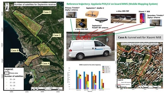
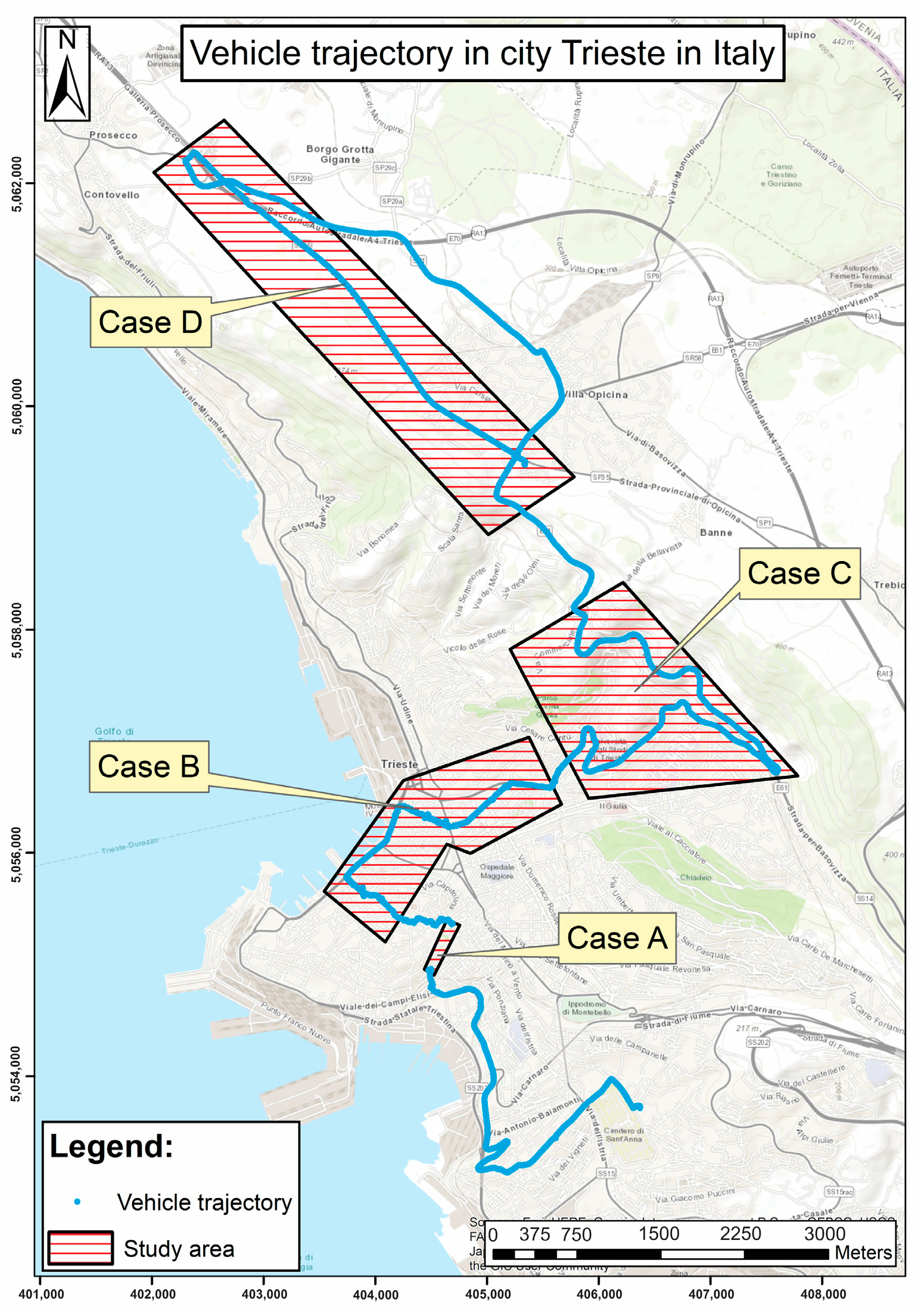
2.1. Survey Experimental Design

For this study, a vehicle from the GeoSNav laboratory of the University of Trieste was used, which was already equipped with a POS/LV (Position and Orientation System/Land Vehicles) Mobile Mapping System from Applanix Corporation, namely Applanix POS LV-420, Version 4 (Applanix, Richmond Hill, ON, Canada). For the purposes of this experiment, the vehicle was additionally equipped with two u-blox devices, namely ZED-F9P and ZED-F9R, an Xiaomi Mi8 smartphone and a Septentrio AsteRx-U geodetic receiver (Septentrio, Leuven, Belgium) with a PolaNt-x MF antenna (Figure 1).

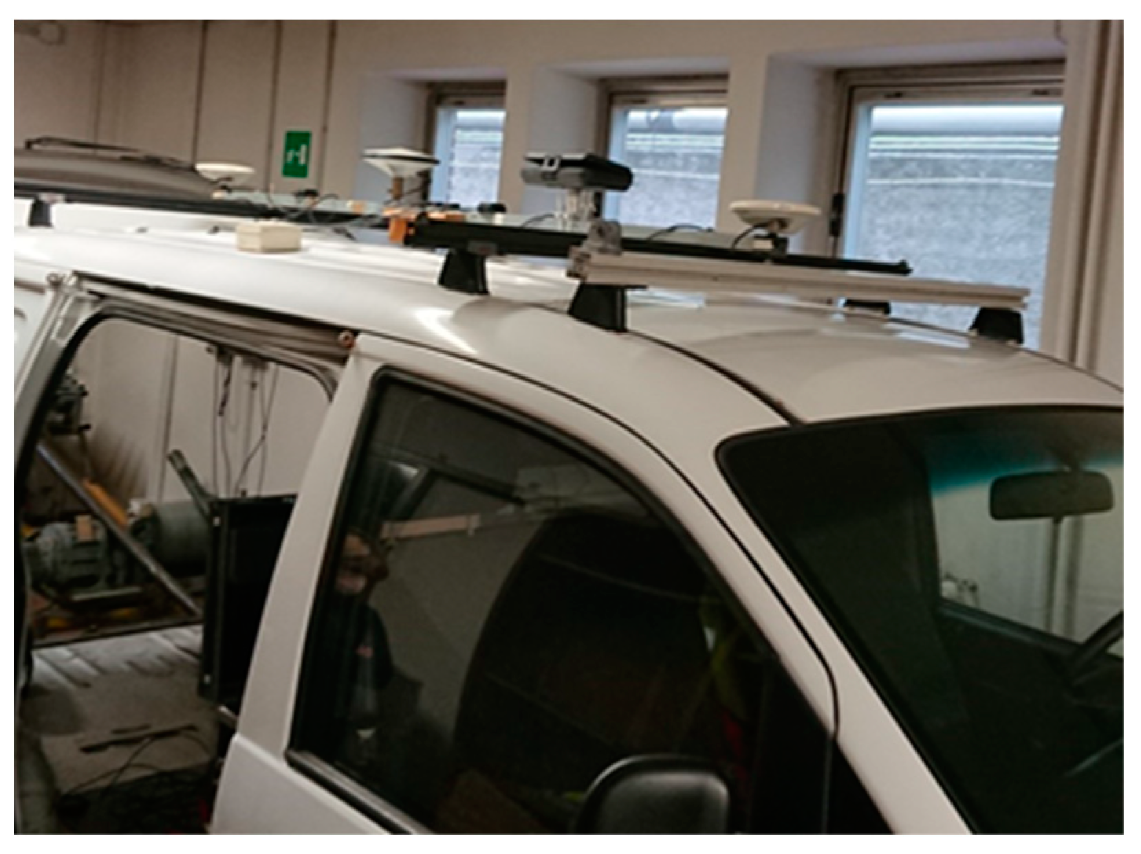
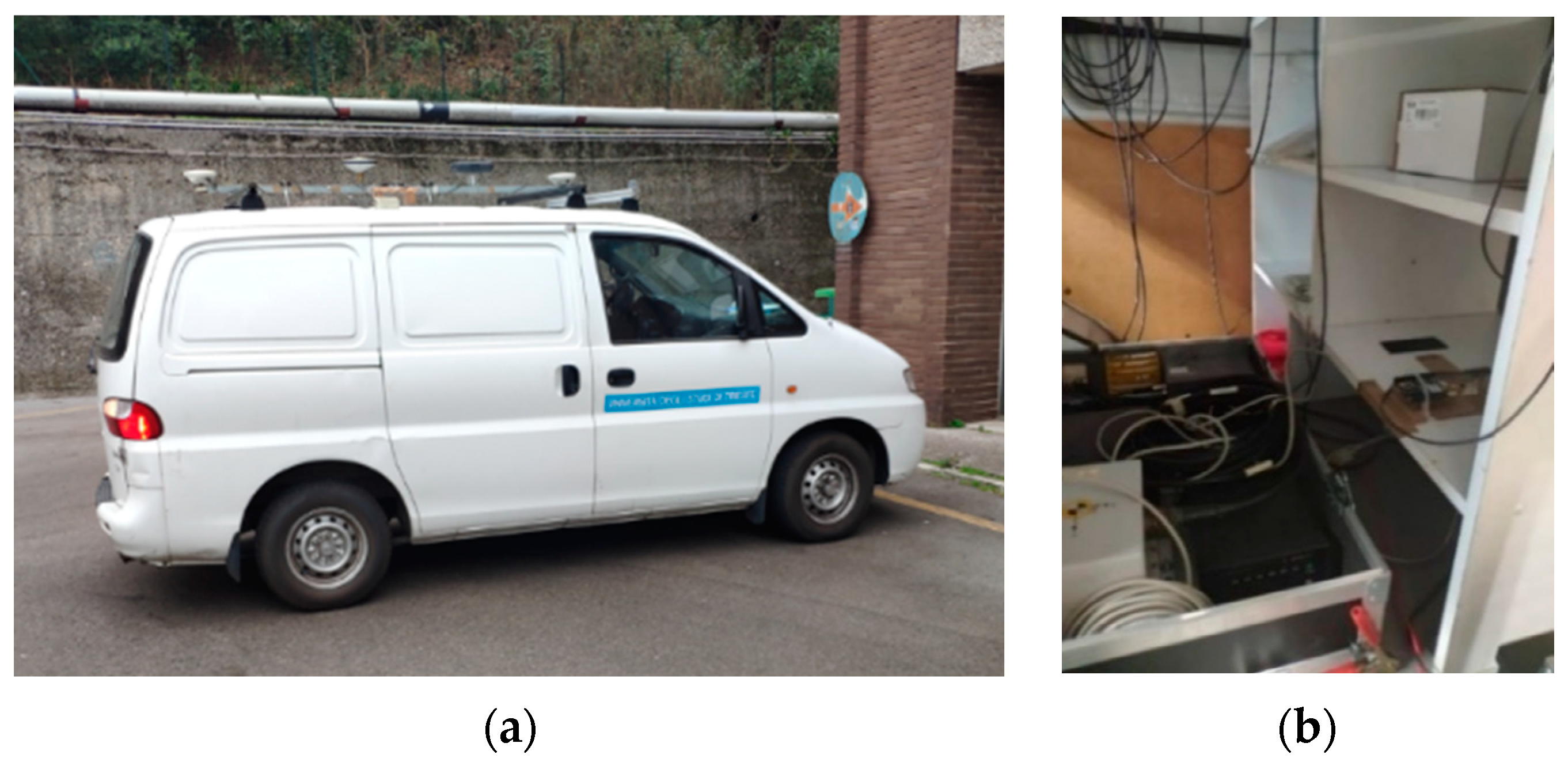
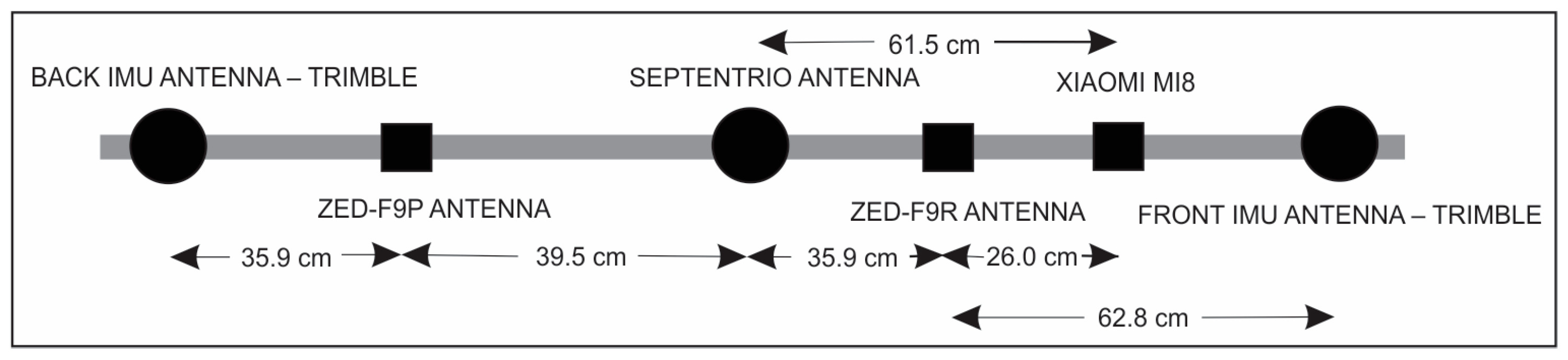
2.2. MMS POS/LV and GNSS Receivers Used in the Study

The antennas of the receivers were located at various positions on the iron shaft mounted on the roof and axial to the vehicle, thus making it easy to measure the horizontal distances between them. They served as a reference for the evaluation positioning results (Figure 2 and Figure 3).
As shown in Figure 2, the central element of the Applanix system, the PCS (POS Computer System), which can process data from various sensors for real-time positioning and stores the data for post-processing analyses (as in the case in the current study), is in the vehicle. The integrated inertial system is a Litton LN-200 Inertial Measurements Unit (IMU) with three accelerometers and three solid-state fibre-optic gyros (Northrop Grumman, Falls Church, VA, USA). Two Trimble Zephyr GPS antennas are mounted on the car roof and connected to two different BD950 GPS cards in the PCS of the Applanix system. The rear antenna is GPS L1/L2 and is used for positioning; the front is GPS L1 and is used for attitude determination. Trimble’s geodetic receivers send positioning and heading data to the PCS, the latter using GAMS (GPS Azimuth Measurement Subsystem). By using a carrier-phase double-difference algorithm to measure the relative position vector between the two antennas, GAMS calibrates IMU and ensures that the azimuth does not drift (when GPS/GNSS coverage exists). During the survey, data from the GPS receivers had an acquisition rate of 1 Hz, while the inertial system sent data to the CPU system at a rate of 200 Hz. The integrated measurements from each sensor were processed using the Kalman filter.
In addition to the Applanix professional system, two SimpleRTK2B boards (Ardusimple, Lleida, Spain) were used for this research, one with a ZED-F9P receiver and the other with a ZED-F9R. The boards were connected to a laptop to provide power to both panels and to store the kinematic observations. The reason for storing the observations directly on the computer with the installed open-source programme from U-Center [44] rather than on the SD card was that based on previous experiments, the memory unit was often overloaded when performing measurements in multi-constellations, thus resulting in gaps in the measurements. The two boards and the laptop were inside the vehicle next to the Applanix system components. Two low-cost antennas ANN-MB-00 were mounted on the roof of the vehicle on a special iron structure already used for GPS Trimble antennas and the Septentrio PolaNt-x antenna (Figure 3).
Another device, the Xiaomi Mi8 smartphone, was mounted parallel to the roof of the vehicle (Figure 1) in the direction of travel. The smart device was in a specially made plastic box so that it was safe, protected and fixed during the measurements. The duty cycle mode was turned off in the smartphone settings because it determines the time the GNSS chip is actively tracking signals and can affect the quality of the GNSS data. This is because the longer the duty cycle, the better the quality of the GNSS observation.

2.3. MMS POS/LV and GNSS Receivers Used in the Study

The kinematic tests were conducted on 11 February 2022 in the city centre of Trieste, Italy, and on the outskirts of the nearby region. The measurements in the city were performed only a few metres above sea level, while for the non-urban area, the measurements were taken on a Karst plateau at an altitude of about 350 metres (Figure 4). To further differentiate the measurement conditions and the behaviour of the different receivers under these conditions, the overall trajectory was divided into different cases: tunnel (Case A), city (Case B) with tall buildings representing a typical urban canyon area, a serpentine road (Case C), and a GNSS vegetation-barrier area in the Karst plateau above Trieste (Case D). The results were compared separately for each of these four areas. To obtain a better idea of the measurement conditions, some characteristic points from the trajectory of the vehicle are shown in Figure 5.

3. Data Processing

The data processing chain implemented in this paper can be described as follows:
  • Analysis of data quality from different receivers operating in GNSS mode;
  • Reference trajectory computation from MMS measurements;
  • Trajectory computation from low-cost devices, namely u-blox ZED-F9P, ZED-F9R, and Xiaomi Mi8, and Septentrio AsteRx-U professional geodetic receiver; and
  • Evaluation of the performances of low-cost GNSS/INS devices compared to the professional MMS system and the Septentrio AsteRx-U geodetic receiver.
The trajectories from all the receivers, including MMS, were computed by the post-processing relative double-difference carrier-phase technique. For the MMS, the Position and Orientation System Post-Processing Package (POSPac™) Mobile Mapping Suite (MMS™) was used [45], which provides a deep level of sensor integration and error modelling and processing modes. For relative double difference positioning, the nearby Trieste reference station (the distance from the study area was around 11 km) belonging to the Antonio Marussi Friuli Venezia Giulia Region GNSS network was used [46]. Observations for geodetic and low-cost receivers, namely u-bloxes and Xiaomi Mi8, were processed using RTKLIB software, demo 5, version b34d [47,48].
RTKLIB is an open-source program package for standard and precise positioning and consists of a portable program library and several APs (application programs). It supports: (1) standard and precise positioning algorithms with GPS, GLONASS, Galileo, QZSS, BeiDou, and SBAS; (2) single, DGPS/DGNSS, kinematic, static, PPP-kinematic and PPP-static positioning modes with GNSS for both real-time and post-processing. A number of features may contribute to its superior performance compared to the software, namely: (a) it is free, while commercial software comes with a cost that can be significant for some users; (b) flexibility in adjusting the processing parameters so that better results can be achieved; (c) possibilities to improve the current version of RTKLIB also by changing some algorithms.
Since the MMS relay on GPS-only constellations, the initial processing strategy for all the used receivers was based only on GPS; successively, a multi-constellation solution using GPS, GLONASS, and Galileo was applied. For static mode ambiguity resolution, the “fix-and-hold” mode was used, which allows a GNSS receiver to maintain positioning even if the number of visible satellites decreases or the measurement quality degrades. In contrast, the “continuous” ambiguity mode was used for kinematic positioning because in this mode, ambiguities are resolved in real time and solutions are continuously updated as new observations become available. Since there were many obstacles along the roads, the lower obstacles were bypassed at the cut-off angle at 15°.
Observations were processed using broadcast ephemerides, iono-free mode, and Saastamoinen’s tropospheric delay model. Unfortunately, there are no available antenna calibrations for the patch antennas of the u-blox receivers ZED-F9P and ZED-F9R and for the Xiaomi smartphones, as there were for the Septentrio AsteRx-U. However, in this research, an approximated antenna phase centre offset was calculated based on the procedure proposed by Netthonglang et al. (2019) [49], which is based on averaging post-processed coordinates in northing and easting (reference was added). This study was performed prior to this particular experiment in the static mode. All additional processing settings used are listed in Table 1.
To investigate the benefits of multi-constellation, observations from the Septentrio AsteRx-U, the ZED-F9P and ZED-F9R u-bloxes and the Xiaomi Mi8 were also processed for GPS, GLONASS and Galileo, but without BeiDou, since the Marussi Network reference station, configured to collect observations from only three constellations, was used for relative positioning. Finally, the provided geographic coordinates were projected into the reference system UTM ETRS.

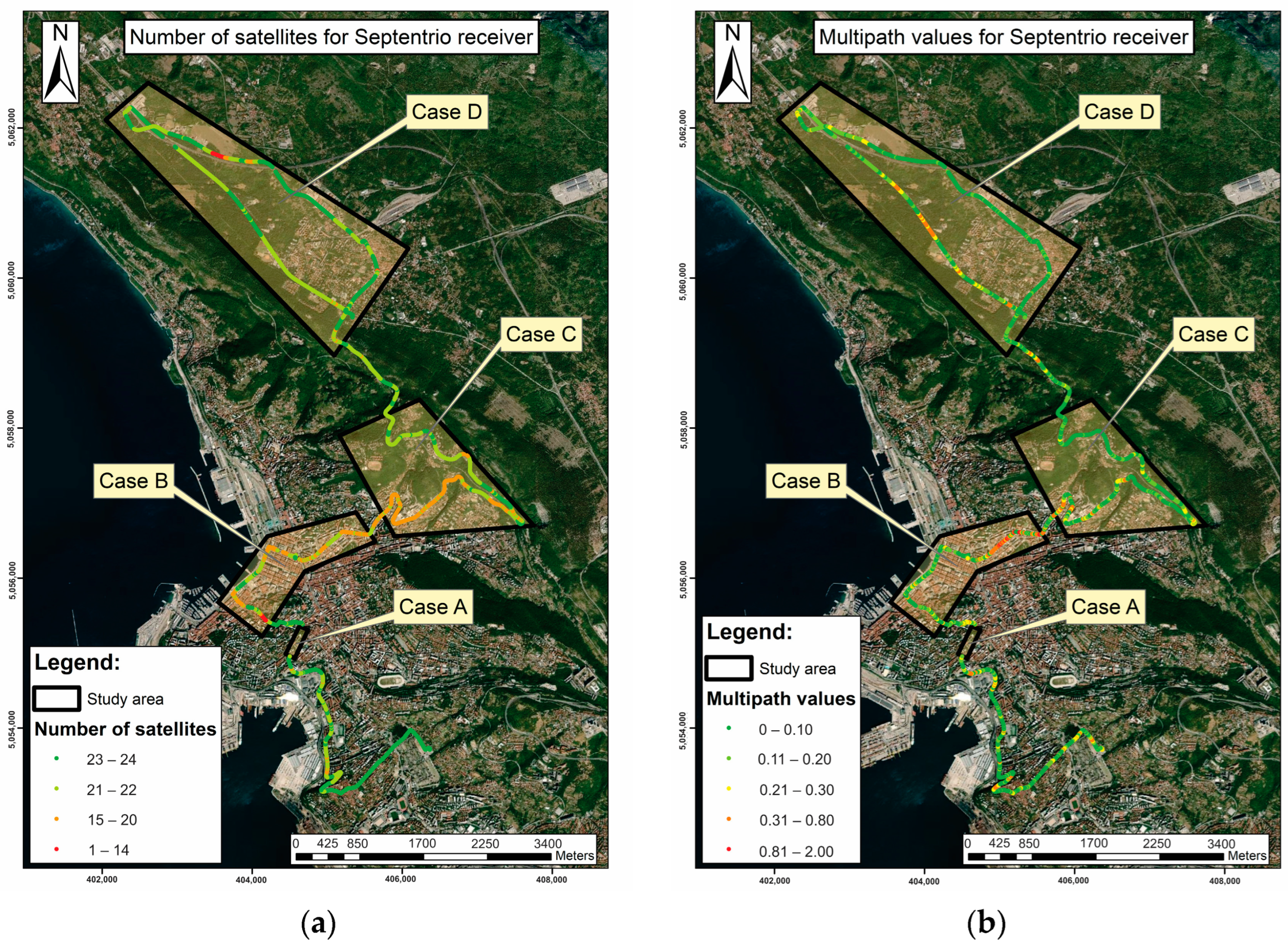
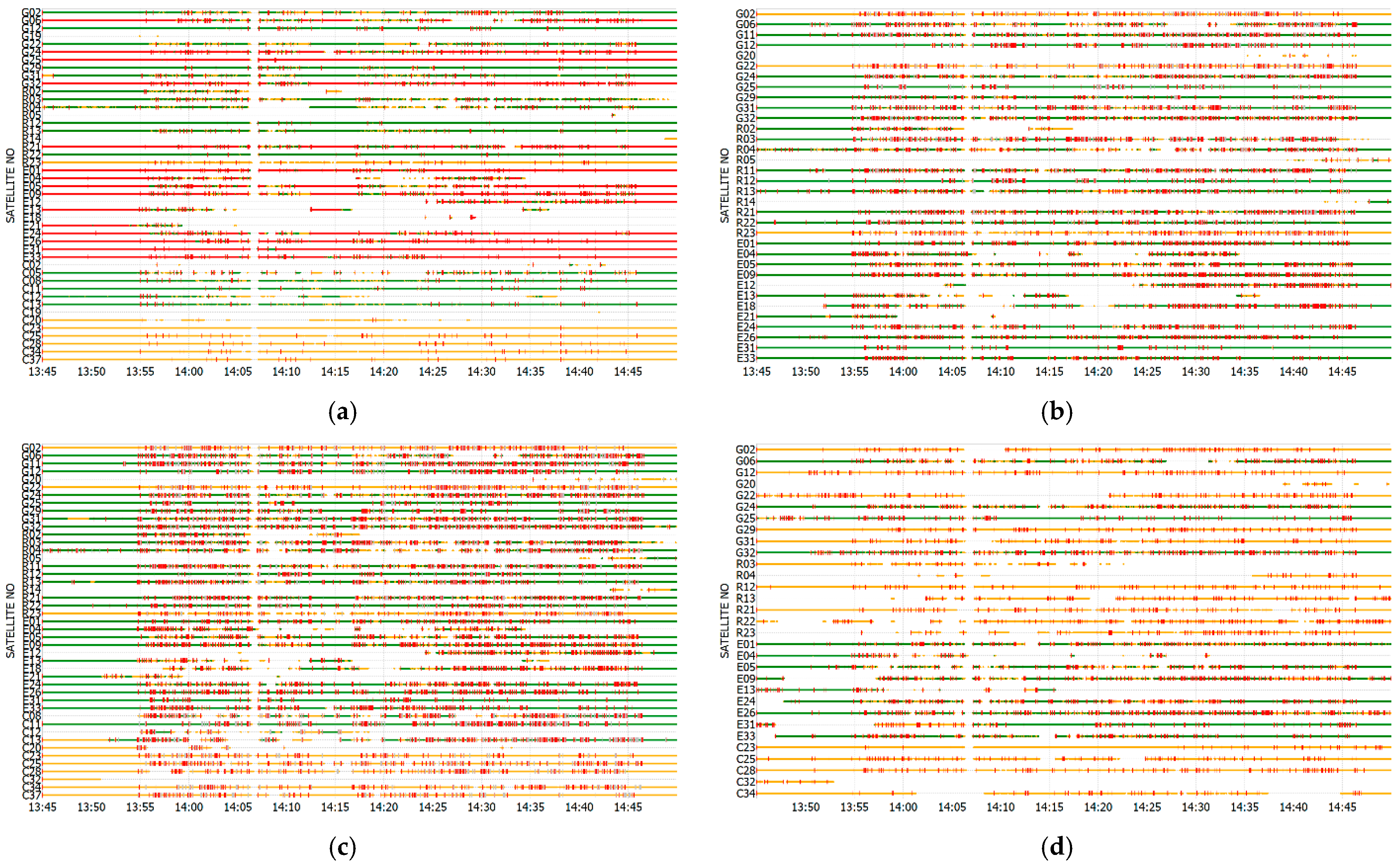
3.1. Quality of GNSS Observations

To compare the performance of the Xiaomi Mi8, the ZED-F9P u-blox, the ZED-F9R u-blox and the Septentrio AsteRx-U receiver, several pre-analyses were performed, namely:
  • Satellite visibility during measurements;
  • Multipath; and
  • Cycle slips for the received signals.
Figure 6 shows the available number of GNSS satellites and the metric quantification of the multipath effect on the L1 frequency of the total trajectory for the Septentrio AsteRx-U geodetic receiver. The figures illustrate the areas with worse measurement conditions, which refer to urban street canyons and areas with lush roadside vegetation, as shown in Figure 6.
Initially, the multipath was estimated; however, furthermore in RTKLIB, a module was used to resolve LLI by using several algorithms, including integer least squares and LAMBDA (Least-Squares Ambiguity Decorrelation). For static sessions, the “fix-and-hold-algorithm was used”, while for kinematic, the “continuous mode” was used (Table 1).
As shown in Table 2, a smartphone was capable of acquiring observations only at the L1 and L5 frequencies, while the u-bloxes were capable only at the L1 and L2 frequencies. From the results, it can be seen that the Septentrio AsteRx-U geodetic receiver, which is equipped with an active geodetic GNSS antenna with built-in low-noise amplifiers that amplify the signals before further processing, and which has a higher gain, performed much better under difficult conditions. The root mean square error (RMSE) for the multipath along the entire track is 0.3554 m, 0.4320 m, and 0.3313 for frequencies L1, L2, and L5, respectively. The smartphone’s multipath estimate is much higher on the L1 frequency band with respect to the Septentrio and two of the u-bloxes, but it reaches the u-bloxes’ results from L1 and L2 on the L5 frequency band. It is also evident that the L5’s Septentrio observations were much less affected by the multipath. The results confirm the fact that L5 signals are less susceptible to multipath because they rely on a higher frequency and wider bandwidth compared to other GNSS signals.
The advantages of the Septentrio AsteRx-U receiver’s active antenna are also evident in Figure 7, which shows the carrier-to-noise ratio (C/N0) in colours and the loss-of-lock indicator (LLI) phenomenon in red lines. LLI is an indicator that shows when the receiver has lost the link or signal to a satellite, resulting in a cycle slip event (Figure 7). This information is particularly useful for GNSS post-processing to improve position accuracy and repeatability. As can be seen in Figure 7, LLIs occur for all receivers during kinematic positioning (from 13:55 to 14:45), but they are less frequent for the Septentrio AsteRx-U antenna. LLIs are also common and quite frequent with the u-bloxes and the Xiaomi Mi8 smartphone in static mode. Overall, the measurements with the Septentrio AsteRx-U were the least affected by LLIs even in kinematic measurements; however, interestingly, the problem was greatest with the ZED-F9R u-blox. Moreover, it can be confirmed that the signal quality of the overall measurements with the Xiaomi Mi8 receiver is significantly worse compared to the u-bloxes, as previously demonstrated by other authors [50], albeit with different smartphones.
LLI indicators show a temporary loss of signal coherence, which could be caused by interference, non-line-of sight conditions, or multipath, and they often produce cycle slips in the receiver. Cycle slips have a significant negative impact on GNSS positioning, but fortunately, they can be recovered during post-processing. The method used by RTKLIB compares the time series of carrier phase measurements from a GNSS receiver with the predicted values calculated from code and carrier phase measurements. The occurrence of a cycle slip is evident by a sudden change in the carrier phase observation, which does not match the predicted value. The software uses the carrier phase residuals or an advanced Kalman filter—the method used in our case—to estimate the carrier phase bias. When the problem is detected, the software adjusts the carrier phase prediction to account for the cycle deviation, thus improving the GNSS position accuracy.

3.2. Quality of GNSS Positioning

The goal of processing the observations was to test the quality of the positions over time, especially in challenging conditions for GNSS. In the following analyses, all the comparisons were made under the hypothesis that the MMS solution is more accurate compared to the other receivers. Since the Applanix system only allows the computation of trajectories in the GPS constellation, all the comparisons were initially performed only in the context of the trajectories generated by GPS; then, the multi-constellation results for Septentrio, u-bloxes, and the smartphone were computed. It could be said that the reference trajectory from Applanix was at an advantage due to operating in GPS/INS mode, while the trajectories from the other receivers were at an advantage due to operating only in GNSS mode. The GPS and GNSS solutions were analysed for the trajectory under consideration, with the percentage determined by the number of total solutions obtained from the MMS. Similar comparisons were then made for the individual cases, i.e., cases A–D, as shown in Figure 4.
The reference coordinates ( e 0 , n 0 , h 0 ) at each epoch t were obtained from the post-processing results of the MMS and computed for the position of the Septentrio AsteRx-U, ZED-F9P, ZED-F9R, and Xiaomi Mi8 smartphone. Since in GNSS positioning, the vertical accuracy can be significantly lower than the horizontal accuracy, especially under difficult conditions such as urban canyons or dense vegetation, the spatial distances d 3 D were estimated separately in further analyses. In each epoch t , they were computed between the considered receivers ( e r e c , n r e c , h r e c ) and the reference receiver ( e 0 , n 0 , h 0 ) , namely:
d 2 D ( t ) = ( e 0 ( t ) e r e c ( t ) ) 2 + ( n 0 ( t ) n r e c ( t ) ) 2 d 3 D ( t ) = ( d 2 D ( t ) ) 2 + ( h 0 ( t ) h r e c ( t ) ) 2
In the quality analysis, the first criterion for the quality of the positioning was the ability to resolve the carrier phase ambiguities, while the second criterion was based on the comparison of the calculated distance ( d 2 D , c o m p u t e d ( t )   and d 3 D , c o m p u t e d ( t ) ) between the Applanix and the specific receiver at the specific epoch (Equation (1)) with the measured horizontal distance between the Applanix and each of the receiver d 0 (see Figure 3). The measured height difference should be zero, since all instruments were placed on the same levelled car mount. The calculation of the deviation of the distances (horizontal and spatial) for each specific epoch t was made separately based on the following equation:
d e v _ d ( t ) = d c o m p u t e d ( t ) d 0
where d stands for either d 2 D or d 3 D .   In addition, since many positions turned out to be outliers, the deviations were analysed for the given threshold. Deviations greater than 1 m, 30 cm, and 10 cm were identified as outliers and removed from the analysis.

3.3. Statistical Testing

To test the equality of variances between two populations, namely GPS and GNSS solutions for each of the receivers, the Fisher–Snedecor test (test F) was used. The null and alternative hypotheses were as follows:
H 0 :   σ G P S 2 = σ G N S S 2 ,   H 1 :   σ G P S 2 σ G N S S 2
based on the assumption that for each test, there were two independent random samples of the deviations in horizontal distances (the same procedure was used for the spatial distances) and the reference ones from Equation (2), namely d e v _ d G P S i , and i = 1 , , n , and d e v _ d G N S S i , d e v _ d G N S S i , and i = 1 , , m , drawn from two normal distributions, N ( μ G P S , σ G P S ) and N ( μ G N S S , σ G N S S ) . To perform the test, a random sample of n should be obtained from one population and a sample of m should be obtained from the second population. The means and variances of the sample followed the equation for GPS or GNSS:
d e v _ d ¯ = 1 n i = 1 n d e v _ d i , s d e v _ d 2 = i = 1 n ( d e v _ d i d e v _ d ¯ ) 2 n 1 ,
while the statistics F for different receivers were based on the equation:
F = s d e v _ d G P S 2 s d e v _ d G N S S 2      
followed F-distribution with n 1 and m 1 degrees of freedom. If the calculated F-score is close to one, the null hypothesis that the samples come from the same populations could be accepted; the more the ratio from Equation (5) deviates from 1, the stronger the evidence for unequal population variances exists. If the F-score is greater than the defined F α / 2 , n 1 , m 1 or less than F 1 α / 2 , n 1 , m 1 for the significance level α , that leads to the conclusion that the null hypothesis (Equation (3)) could be rejected, and it could be stated that the variances from the two different solutions were not the same in both groups.

4. Results and Discussion

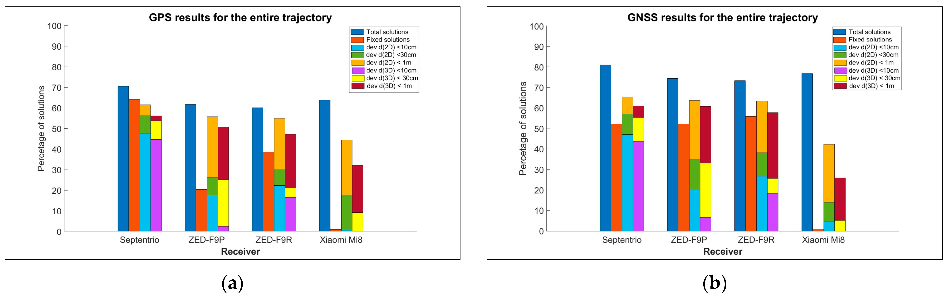
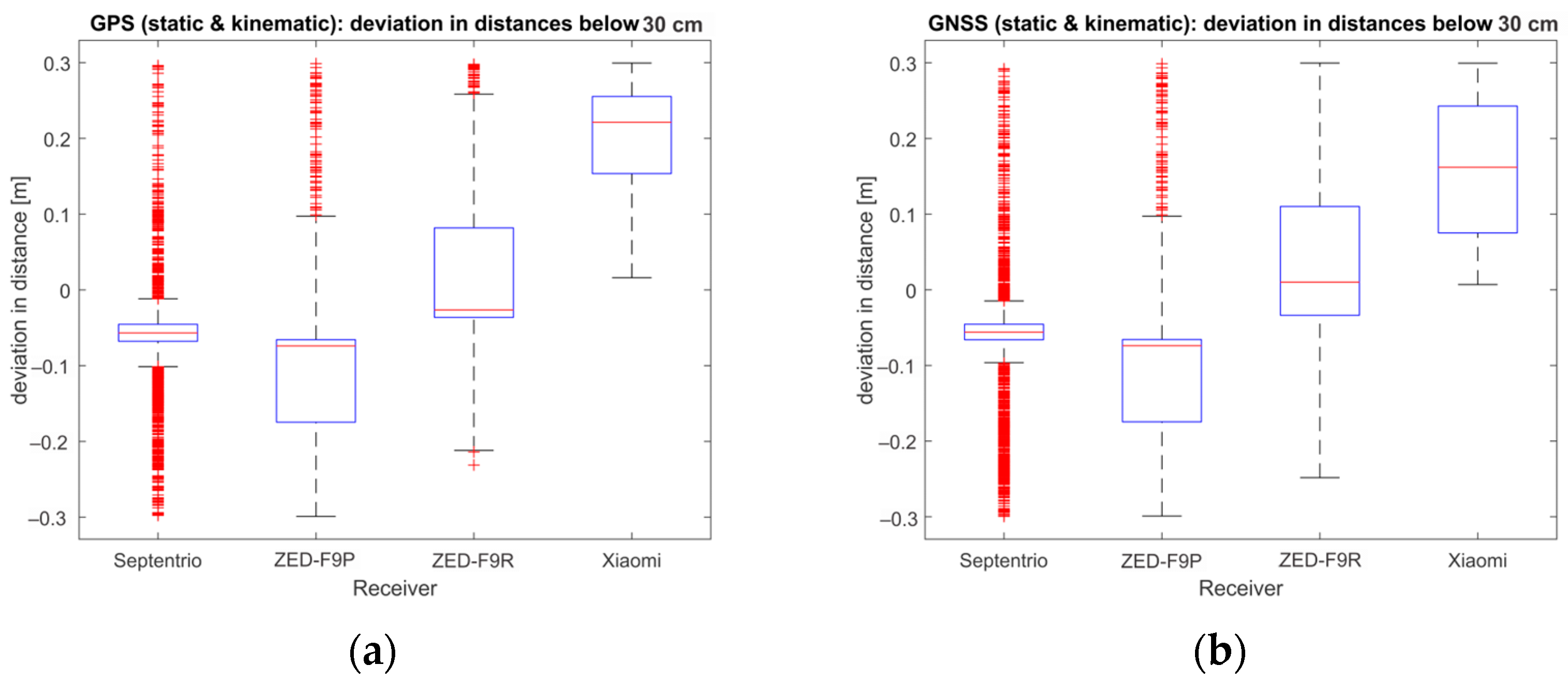
4.1. Entire Trajectory: Static and Kinematic Sessions

This scenario consisted of a static session (10 min) at the beginning of the survey, a kinematic session that lasted approximately 50 min, and a final 10 min static session after calibration of the Applanix system. The comparison of the solutions of GPS and GNSS (Table 3 and Table 4, Figure 8) shows that in the case of GNSS, many more positions could be obtained on the whole trajectory when the observations were processed in the multi-constellation mode. For the Xiaomi Mi8 phone, almost all ambiguities were determined as floats, although the range of deviations in distances was in the same range as for the u-bloxes, albeit it is still slightly worse.
From Figure 8, it can be seen that the Septentrio AsteRx-U receiver outperformed all the other receivers both in terms of the number of total solutions and the number of fixed solutions. From GPS, 62% of all the available solutions were those where the deviations of the calculated distances from the (measured) reference distances were less than 1 m, and they were 57% and 48% where the deviations were less than 30 cm and 10 cm, respectively. The results are slightly better for the GNSS solutions.
From the overall trajectory statistics, it can be seen that the Xiaomi Mi8 allowed more usable solutions than the u-blox receivers; however, in 99% of cases, the ambiguities were detected as floats. For the phone, 44% of the possible GPS solutions were those where the deviation of the distances from the reference positions was less than 1 m, while 18% and 1% of the total positions on the trajectory were those where the deviations were less than 30 cm and 10 cm, respectively. For the GNSS solutions, only 14% and 5% of the GNSS solutions were those where the deviations of the distances were less than 30 cm and 10 cm, respectively. The results from the u-bloxes are interesting, wherein ZED-F9R seemed to perform better than ZED-F9P both in the number of fixed solutions and in the quality of positioning.

Results with Deviation in Distances and Heights below 30 cm

The statistics for the filtered deviation of distances (Table 5 and Table 6) that were less than 30 cm show that the Septentrio AsteRx-U receiver performed better than others in the number of available solutions (47.5% for the GPS and 57.1% for the GNSS), with deviations in distances calculated with a mean of −5.8 cm ± 6.5 cm for the GPS solutions (Table 5) and −6.0 cm ± 8.4 cm for the GNSS solutions (Table 6). One of the possible reasons for the larger standard deviations in the GNSS solutions could be the fact that Applanix worked in GPS/INS mode; therefore, the results from the GPS are more appropriate for comparisons. Nevertheless, it is noticeable that despite the percentage of GNSS being higher (81.0%) in terms of the GPS-only solutions (70.5%), the number of solutions calculated with fixed ambiguities is correspondingly lower (2176 compared to 2320), which is probably due to the possible insufficient performance of one of the systems used in the multi-constellation solution.
It is also even clearer from the graphical representation of the statistics for the deviation of distances of less than 30 cm for all receivers that the Septentrio AsteRx-U receiver was much better at determining the correct position. For the Xiaomi Mi8, the median of the receiver deviates the most compared to the others. The overall scatter is smallest for the Septentrio and largest for the ZED-F9R; the width between each quartile and the scatter is much smaller for the Septentrio than for the other receivers. The situation is the same for both GPS (Table 5, Figure 9a) and GNSS processing (Table 6, Figure 9b). The interquartile range between the GPS and the GNSS for the ZED-F9R and the Xiaomi Mi8 changes drastically. Since there is no overlap between the boxes in any of the Figure 9 plots, it can be concluded that there is a clear difference between the data sets from different receivers. An F-test was used to detect differences in the variances for the GPS and GNSS solutions. The results are shown in Table 7.
For the comparison of the variances between the two groups for each of the receivers separately, i.e., the first group represents the GPS solutions and the second represents the GNSS solutions, in both cases, the null hypothesis H0 that means and variances are equal cannot be rejected. However, the number of possible solutions from the GPS processing in terms of the GNSS is much lower (see Table 5 and Table 6).

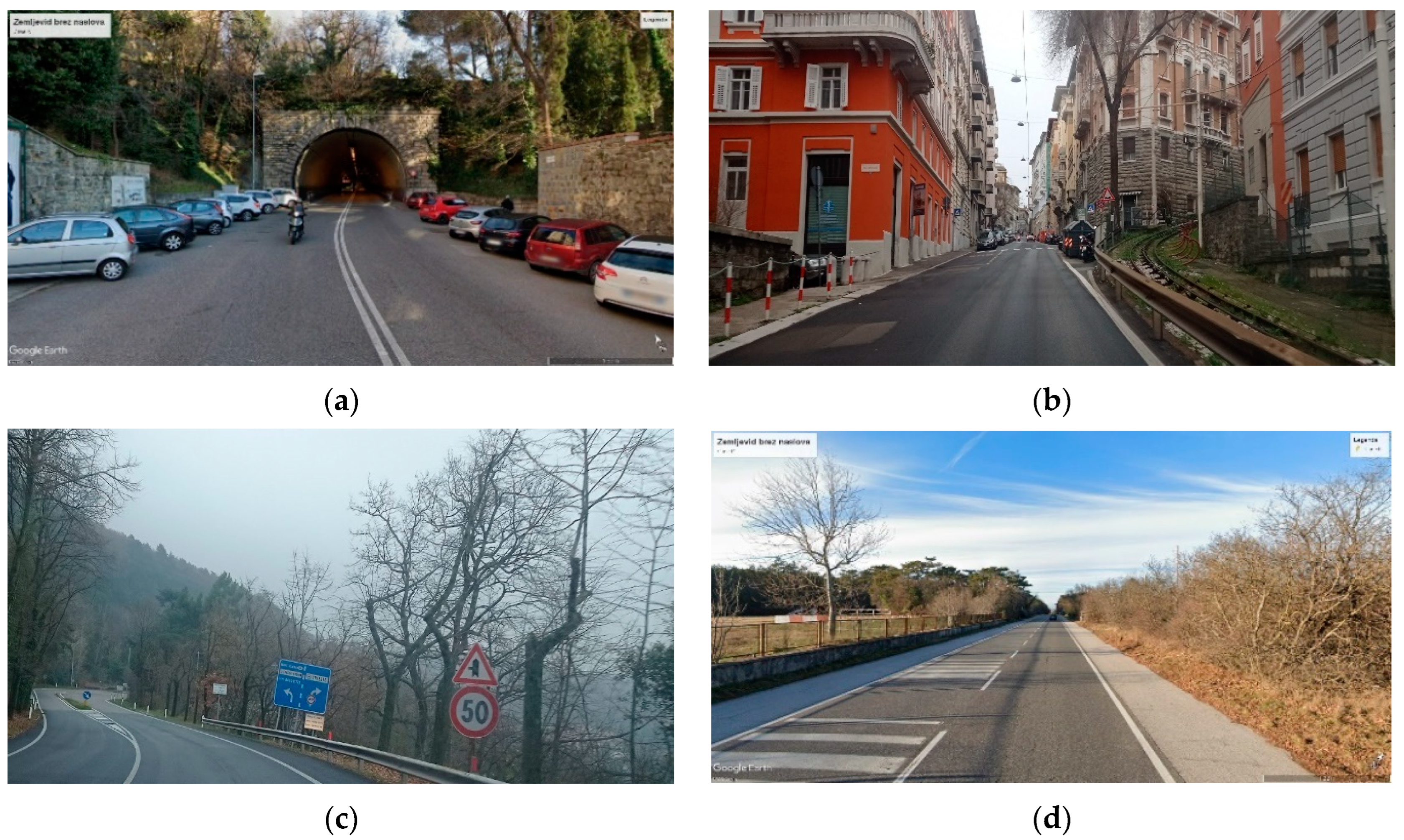
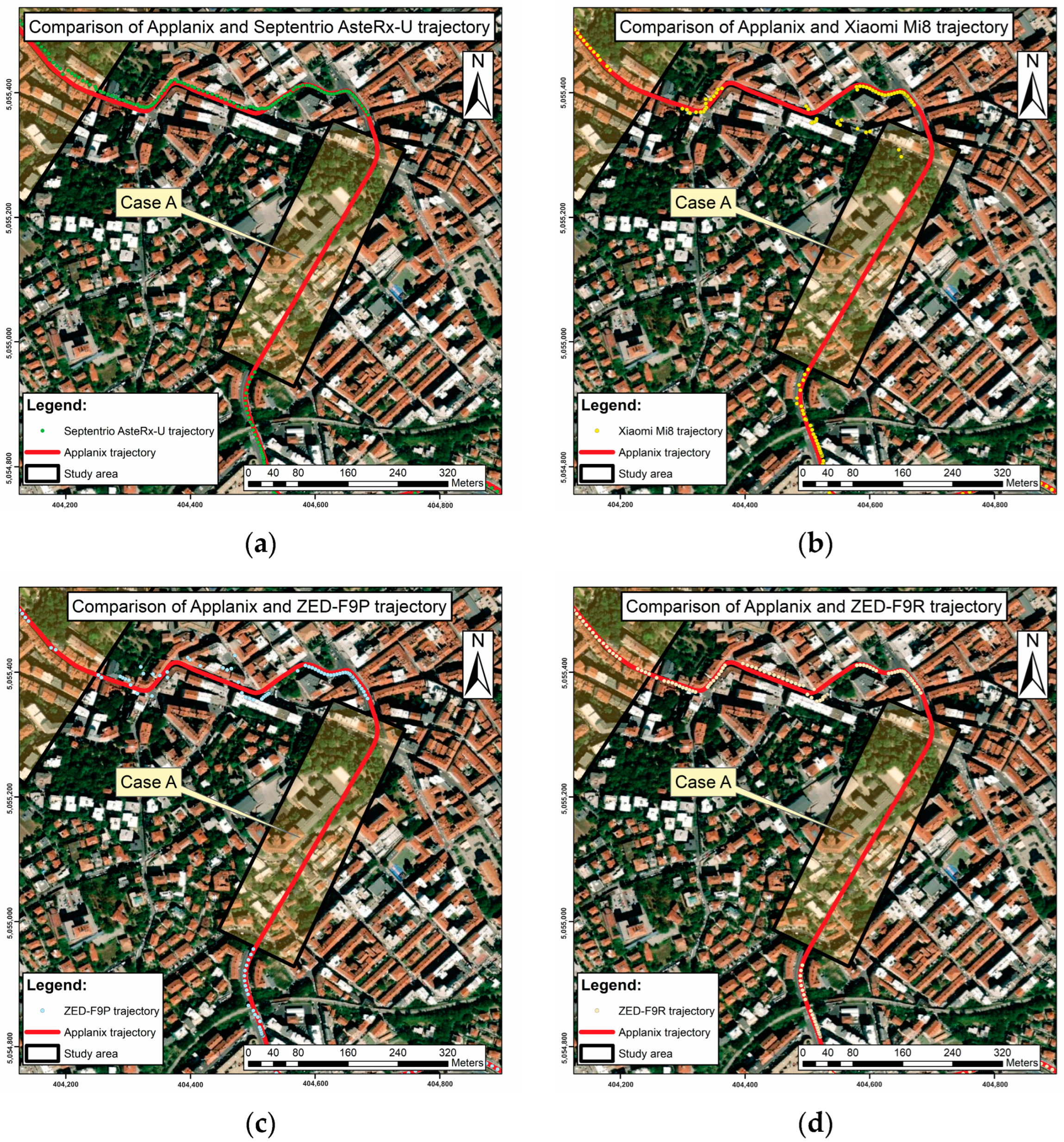
4.2. Case A—Tunnelling

For the topographic survey at the tunnel exit (Figure 10), the main goal was to investigate when the receivers can recover their position after leaving the tunnel and how much they deviate from the reference position. This information can be found in Table 7.
After exiting the tunnel, the Xiaomi Mi8 was the last device to recover its position ( d a l o n g ) at about 57 m, while the other devices were able to recover their position slightly earlier—after 30 m in the case of the ZED-F9P (Table 8). The performance of the Xiaomi Mi8 and the ZED-F9P in the segment after leaving the tunnel was the worst among all the receivers tested (see Figure 10b). Interestingly, the Septentrio and ZED-F9R receivers recovered their position much better than the others, which deviated up to 2 m ( d c r o s s t r a c k ) from the Applanix trajectory (Figure 10). However, these are the results for this case; therefore, the findings cannot be generalised to other situations at this stage.

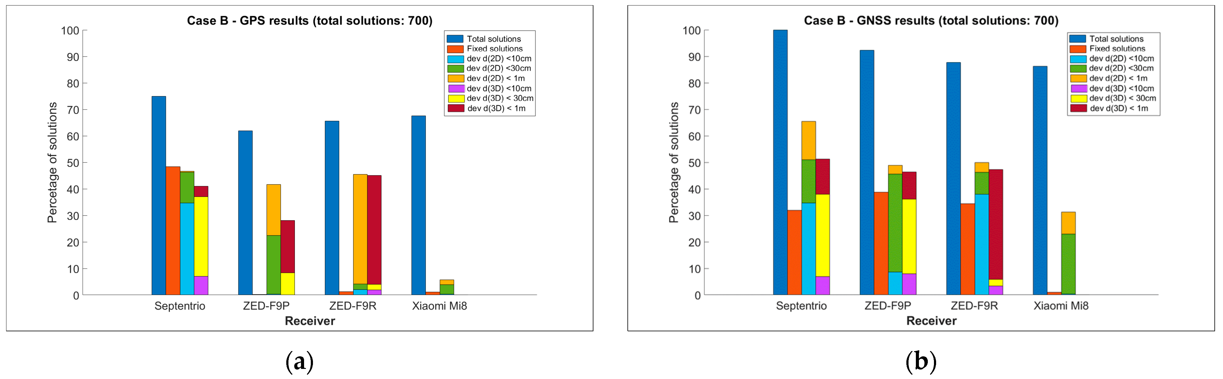
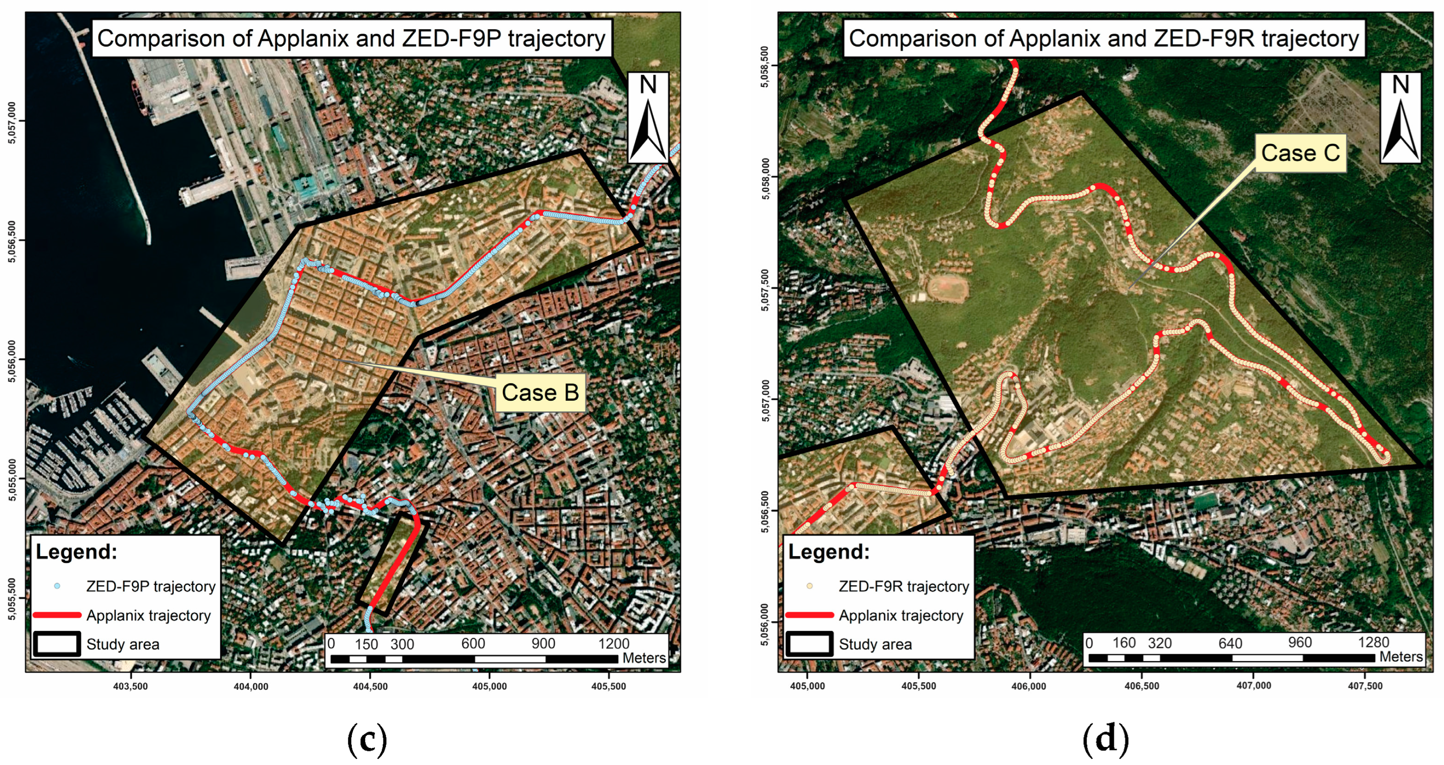
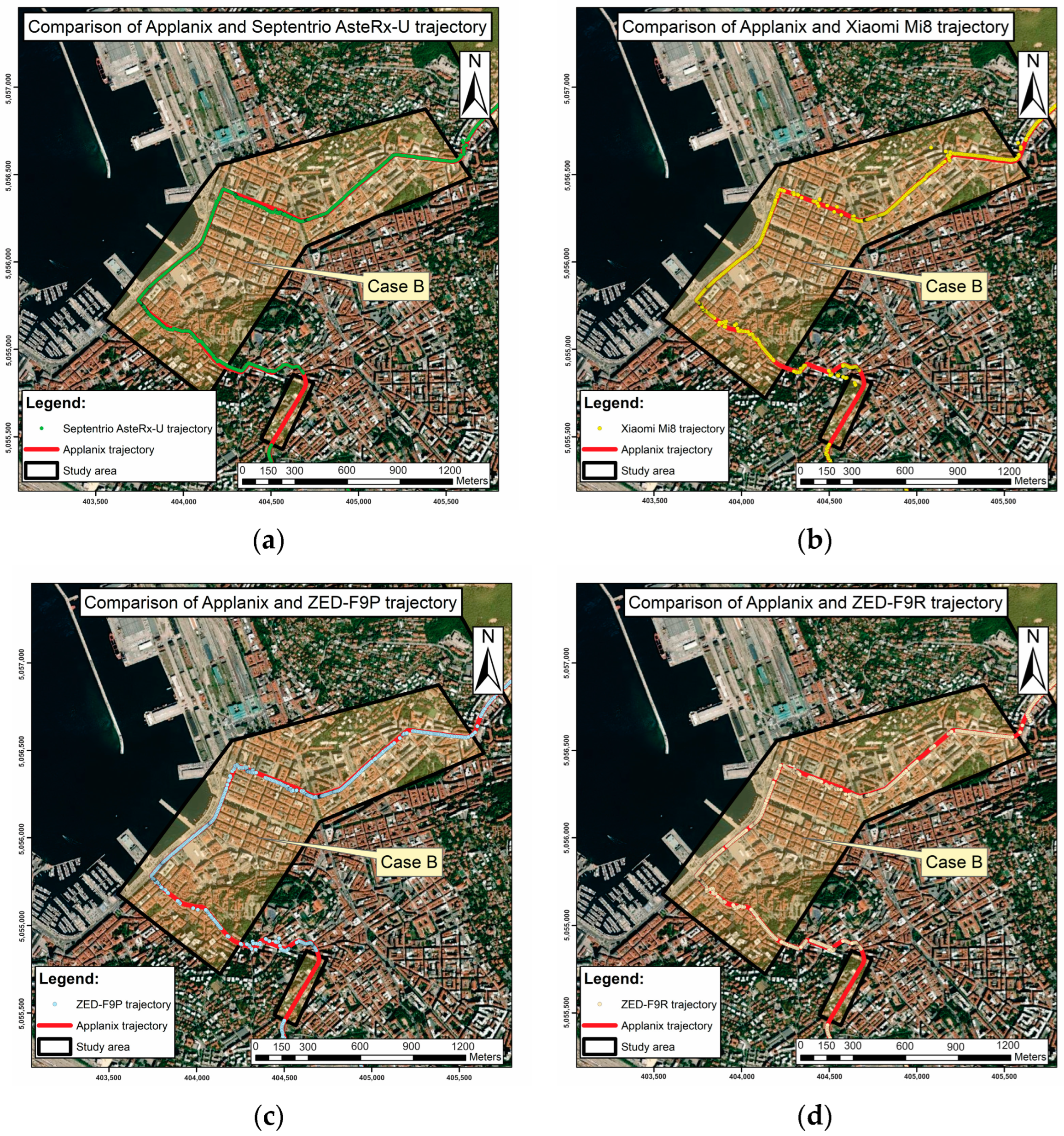
4.3. Case B—Urban Canyons

In urban areas, there should be a total of 700 solutions; however, due to the obstacles, far less appropriate solutions could be obtained (Table 9 and Table 10, Figure 11).
Figure 11 shows that the Septentrio was able to determine the position for Case B (surveying in urban areas) most of the time, while the other receivers had difficulty determining the position in urban street canyons, especially the Xiaomi Mi8 phone receiver, where some of the positions deviated greatly from the reference positions. Both the u-bloxes and the Xiaomi Mi8 were only able to delineate 1.1% and 1.3% of the possible solutions with fixed ambiguities, respectively. As for the deviation of the distances, 46.3% of the Septentrio were below 30 cm and 34.7% were below 10 cm, while the others, especially the ZED-F9R and the Xiaomi Mi8, were less successful, with only 4.1% of the positions where the deviations were below 30 cm and small percentages (0.3%, 2.0% and 0.3% for the ZED-F9P, ZED-F9R and Xiaomi Mi8, respectively) where the deviations from the reference positions were below 10 cm.
Comparing the positioning of the GPS and GNSS (Table 9 and Table 10 and Figure 12), it is clear that a larger number of satellites (e.g., when using the GNSS) leads to a higher number of calculated positions compared to the GPS and often to better quality positioning, as can be seen in particular for the two u-blox receivers and the Xiaomi Mi8 smartphone. For those devices, there is also a very significant improvement in the determination of the fixed ambiguities in the case of the GNSS, while for the Septentrio AsteRx-U receiver, there is a decrease; this mainly leads to an improvement in accuracy for the deviations below 1 m but less for the other thresholds (30 cm and 10 cm). For positioning, it is also seen that much more data can be acquired in GNSS mode than in GPS mode. The same is true for positioning performance. The GNSS solutions show a significant improvement in deviations between the receivers and the Applanix of less than 1 m or 30 cm for all the low-cost receivers tested and 10 cm and an improvement in deviations below 10 cm for the two u-blox devices, especially for the ZED-F9R. From Figure 12a,b, it can be seen that for the entire trajectory the horizontal positioning was clearly better compared to the spatial one. Unfortunately, the positioning of the Xiaomi Mi8 smartphone in urban areas has not proven to be adequate, as few GNSS solutions have managed to be positioned below the threshold of qualitative accuracy; all of them refer to adequate horizontal positioning, while spatial positioning has failed in all epochs for Case B.

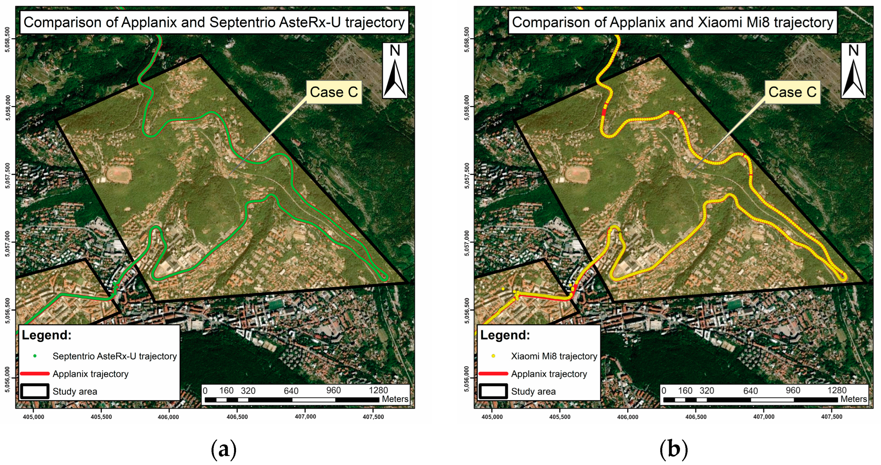
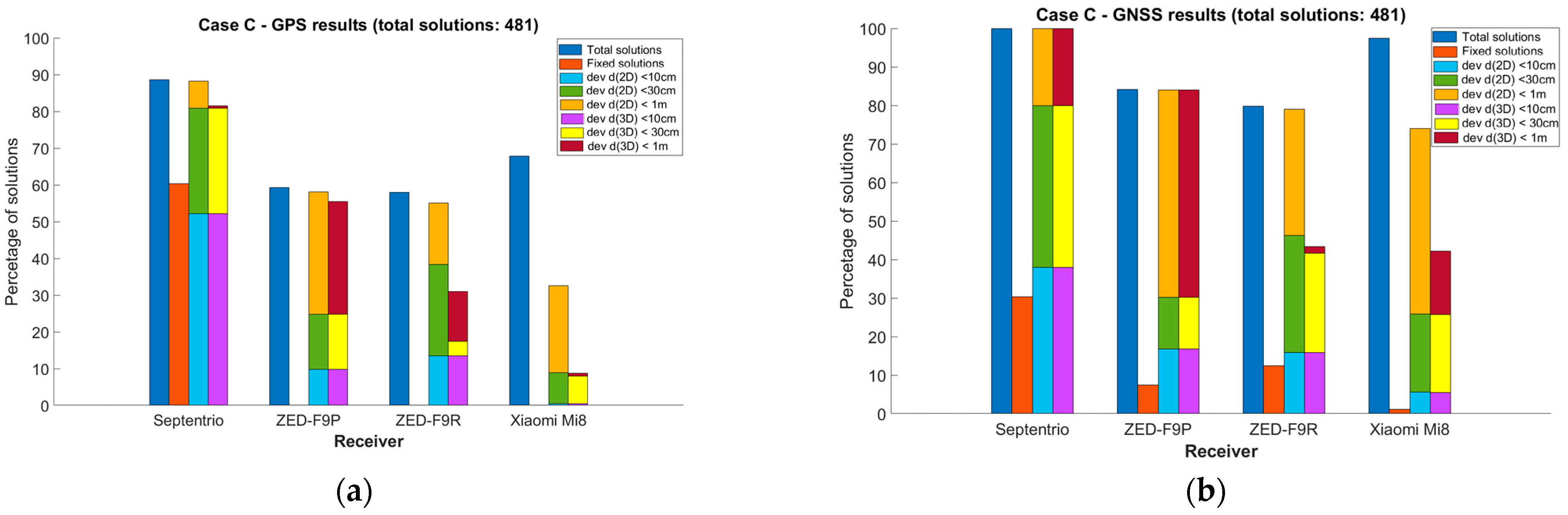
4.4. Case C—Area with Curves and Serpentines

The example refers to a situation with fixed barriers along the road, although occasional vegetation barriers were present, but they were not vegetated due to the winter season. In this case C, the elevation of the trajectory gradually increased, resulting in a road shape with multiple curves. Figure 13 illustrates how the receivers in this area performed in GNSS positioning.
From the graphical representation (Figure 13 and Figure 14), it is already clear that the Septentrio AsteRx-U geodetic receiver outperforms the other receivers in the number of detected positions. Interestingly, however, the Xiaomi Mi8 also detected more positions than the two u-bloxes. However, the quality of the position determination for the smartphone is significantly worse compared to the u-bloxes (Table 11 and Table 12, Figure 14).
As in case B, the u-bloxes were able to determine many more fixed solutions in GNSS mode; however, as in the other cases, this was not true for the Septentrio AsteRx-U. The majority of all the available solutions were achieved with a deviation of the distances from the (measured) reference of less than 1 m for the Septentrio and 84.0%, 79.0% and 79.4% of the solutions for ZED-F9P, ZED-F9R, and Xiaomi Mi8, respectively. At the 30 cm threshold, the Septentrio was superior to the other receivers, as 80.0% of the solutions were less than 30 cm and 37.9% of the solutions were less than 10 cm. The GNSS solutions were significantly better for all the receivers with respect to the GPS.

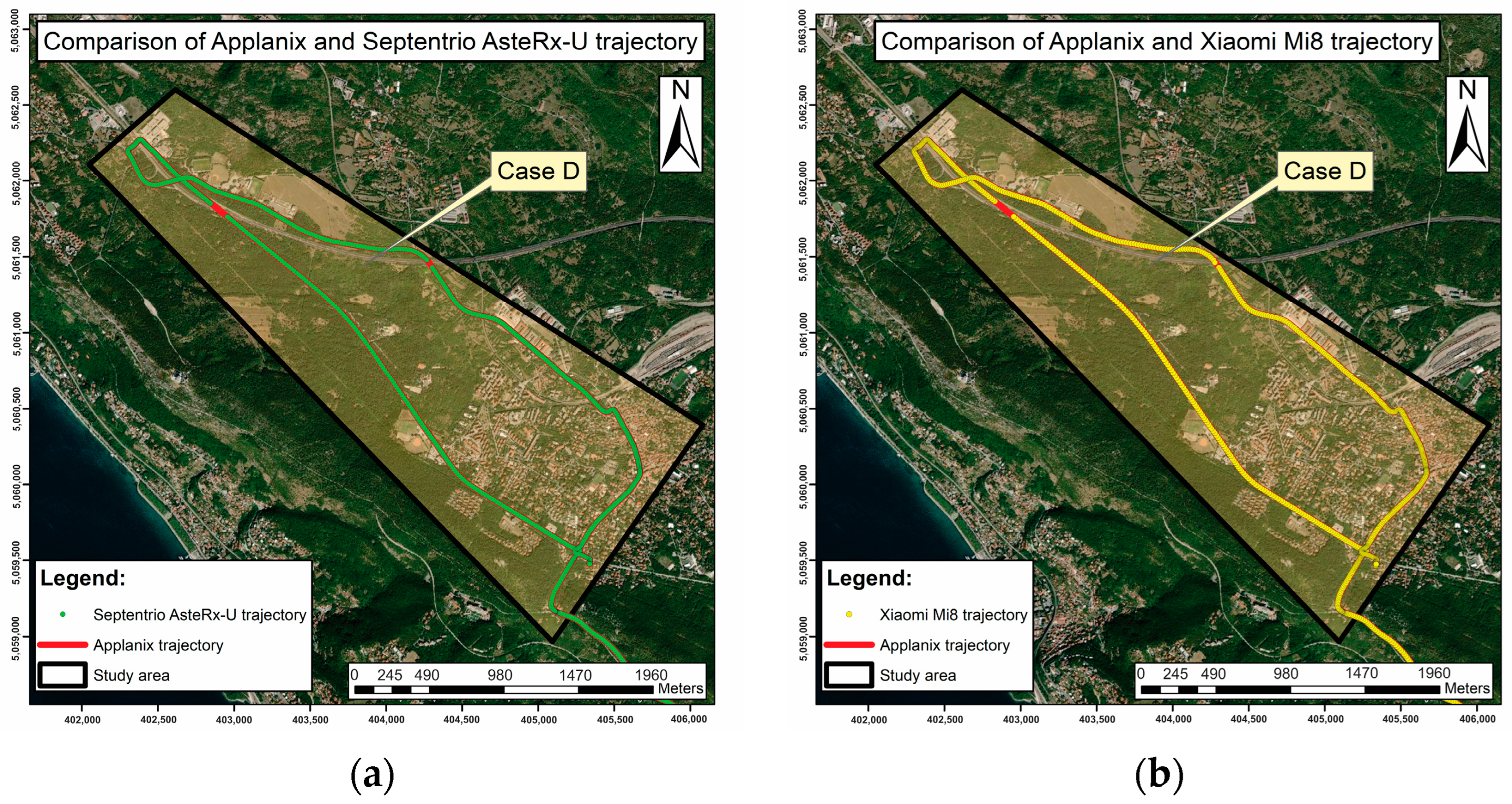
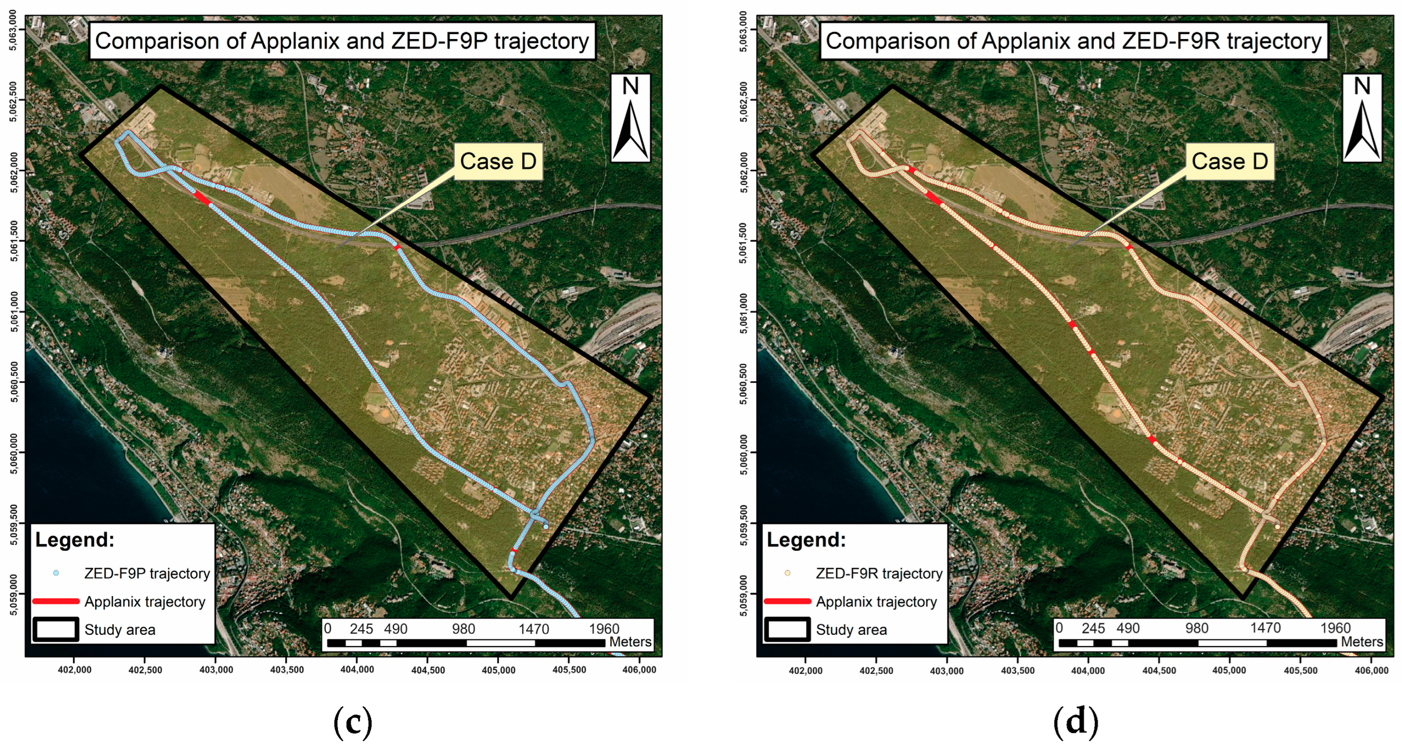
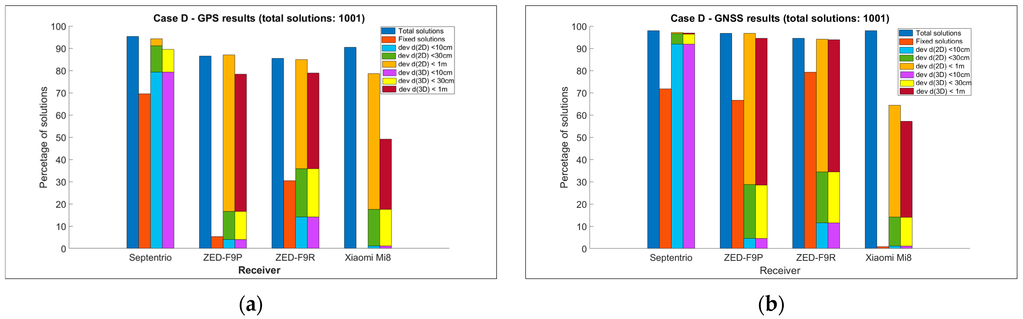
4.5. Case D—Area with Vegetation by the Roadside

The last case D involved a section of the trajectory that was kept flat, with some vegetation barriers near the roadway, which were less leafy due to it being winter. The measurement took place on the outskirts of the city, on the karst plateau, mostly at an altitude of about 300 m above sea level. Figure 15 shows that all the receivers except the ZED-F9R were able to determine the position in most of the section. As in the previous cases, the quality of position determination with the Xiaomi Mi8 was significantly worse than that of the other receivers (Table 13 and Table 14, Figure 16).
In addition, in terms of possible positioning and in situations with fixed ambiguities, the results using the GNSS are much better than with the GPS only. Again, with the Xiaomi Mi8 smartphone, it was not possible to define the ambiguities as fixed. The geodetic receiver also performed much better in this case than the other receivers in terms of the quality of the position determination. Interestingly, fixed solutions have prevailed in GSS processing with respect to GPS, especially for ZED-F9P and ZED-F9R. The deviation of the calculated horizontal distances from the reference distances was less than 10 cm in 91.9% of the total epochs. Interestingly, the Xiaomi Mi8 smartphone performed well in situations with a threshold of less than 1 m, but in all the situations, the u-bloxes were superior to the Xiaomi Mi 8. The ZED -F9P and Xiaomi Mi8 only achieved positioning quality below 10 cm in a few situations; in this case, the ZED-F9R was slightly better, but it was definitely not comparable to the highly successful Septentrio AsteRx-U.

5. Conclusions

In this paper, the observations and position quality of a Septentrio AsteRx-U geodetic receiver, two u-blox receivers –ZED-F9P and ZED-F9R– and a Xiaomi Mi8 smartphone operating in GPS only and GNSS modes were analysed in relation to the Applanix MMS trajectory results. The study was carried out in urban and non-urban areas and in GNSS favourable measurement conditions. The results obtained in this research lead to the following conclusions, especially in terms of the low-cost used devices:
  • From the comparison of the GPS only and GNSS solutions for geodetic and low-cost receivers, it can be concluded that in terms of the GPS, GNSS processing achieved many more solutions for position determination and determined ambiguities in many more cases with fixed values, even if this is not true in general for the Septentrio AsteRx-U and in particular in case C: a non-urban area with curves and serpentines characterised by a reduced signal acquisition. Comparing the means and standard deviations of the deviation of the distances from the reference, it can be stated that the variances for the GPS and GNSS solutions were comparable in this case.
  • There is a significant difference in quality between kinematic positioning with geodetic and low-cost receivers. The geodetic receiver is much more stable in ambiguity solutions, especially when compared to a smartphone. The same is true for solutions where the threshold for positioning quality is set at 30 cm and even more clearly at 10 cm. The differences certainly also relate to the design of the receiving antenna. The geodetic GNSS antenna enables the elimination of some multipath signals and obviously outperforms the small antenna of a smartphone and the patch antenna of the u-bloxes. Therefore, it can be said that caution should be exercised when using low-cost receivers in terrestrial measurements in urban environments, and further studies and research are required in order to eliminate observations that are loaded with effects (these can be multipaths or interferences).
  • Care should also be taken when moving out of shaded areas that make GNSS positioning impossible, especially with low-cost receivers. In the future, when processing combined GNSS and INS observations in the Kalman filter for low-cost receivers, it would be useful to include the new GNSS resolution obtained from the transient in the final solution, since the solutions—especially for the low-cost receivers—deviated significantly from the Applanix reference solutions immediately after repositioning.
  • In situations with many curves and manoeuvres on the road, the low-cost receivers also performed worse compared to the geodetic receiver; in these situations, they determined significantly fewer positions than the Septentrio AsteRx-U receiver. Since this portion of the trajectory may have also been affected by the poor survey conditions due to vegetation, further research is required in order to determine how the receivers respond in curves and turns in the open sky.
  • In GNSS mode, the Xiaomi Mi8 smartphone performed well in situations with a threshold of less than 1 m, with the percentages varying from 50% for the urban areas to 80% for the non-urban areas, which offers potential in view of future improvements for applications in terrestrial navigation.
  • The general conclusion is that even low-cost devices, especially u-blox receivers and in particular those operating in GNSS/INS mode, are suitable for kinematic terrestrial positioning; however, their use in problematic positioning areas and in urban environments with obstacles should be treated with greater caution than is the case when using professional geodetic receivers.
Future studies will focus on the fusion of GNSS and MEMS (Micro-Electro-Mechanical System) sensors in smartphones and u-bloxes to enable more accurate and continuous positioning using the Kalman filter, especially in problematic environments such as street canyons, dense vegetation and under conditions of intentional interference, namely jamming and spoofing.

Author Contributions

Conceptualization, R.C. and P.P.-P.; methodology, R.C., P.P.-P. and F.V.; software and validation F.V. and P.P.-P.; formal analysis, P.P.-P. and F.V.; field tests: F.V., R.C. and T.S., P.S. and P.P.-P.; writing—original draft preparation, P.P.-P. and F.V.; writing—review and editing, R.C.; visualization, F.V. and P.P.-P.; project administration, R.C. and P.P.-P. All authors have read and agreed to the published version of the manuscript.

Funding

The authors acknowledge the financial support of the Slovenian Research Agency (research core funding No. P2-0227 Geoinformation Infrastructure and Sustainable Spatial Development of Slovenia).

Data Availability Statement

The data supporting the results of this study are available at https://unilj-my.sharepoint.com/:f:/g/personal/ppavlovc_fgg_uni-lj_si/EnrZ6jQl_DtIg4rVMZVNMUkBCqJdv5NC2oyrBsQpI2wiew?e=ukq78M (accessed on 7 January 2023).

Conflicts of Interest

The authors declare no conflict of interest.

References

  1. Groves, P.D. Shadow matching: A new GNSS positioning technique for urban canyons. J. Navig. 2011, 64, 417–430. [Google Scholar] [CrossRef]
  2. Ben-Moshe, B.; Elkin, E.; Levi, H.; Weissman, A. Improving accuracy of GNSS devices in urban canyons. In Proceedings of the 23rd Annual Canadian Conference on Computational Geometry, Toronto, ON, Canada, 10–12 August 2011. [Google Scholar]
  3. Xi, C.; Cheng-Dong, X. Performance analysis of multi-constellation GNSS in urban canyons based on fuzzy comprehensive evaluation. In Proceedings of the 29th Chinese Control And Decision Conference (CCDC), Chongqing, China, 28–30 May 2017; pp. 3040–3045. [Google Scholar] [CrossRef]
  4. Fortunato, M.; Ravanelli, M.; Mazzoni, A. Real-time geophysical applications with Android GNSS raw measurements. Remote Sens. 2019, 11, 2113. [Google Scholar] [CrossRef]
  5. Magalhães, A.; Bastos, L.; Maia, D.; Gonçalves, J.A. Relative positioning in remote areas using a gnss dual frequency smartphone. Sensors 2021, 21, 8354. [Google Scholar] [CrossRef]
  6. Angrisano, A.; Gaglione, S. Smartphone GNSS Performance in an Urban Scenario with RAIM Application. Sensors 2022, 22, 786. [Google Scholar] [CrossRef]
  7. Li, Y.; Cai, C.; Xu, Z. A Combined Elevation Angle and C/N0 Weighting Method for GNSS PPP on Xiaomi MI8 Smartphones. Sensors 2022, 22, 2804. [Google Scholar] [CrossRef]
  8. Paziewski, J.; Fortunato, M.; Mazzoni, A.; Odolinski, R. An analysis of multi-GNSS observations tracked by recent Android smartphones and smartphone-only relative positioning results. Meas. J. Int. Meas. Confed. 2021, 175, 109162. [Google Scholar] [CrossRef]
  9. Robustelli, U.; Paziewski, J.; Pugliano, G. Observation quality assessment and performance of GNSS standalone positioning with code pseudoranges of dual-frequency android smartphones. Sensors 2021, 21, 2125. [Google Scholar] [CrossRef]
  10. Bakuła, M.; Uradziński, M.; Krasuski, K. Performance of DGPS Smartphone Positioning with the Use of P(L1) vs. P(L5) Pseudorange Measurements. Remote Sens. 2022, 14, 929. [Google Scholar] [CrossRef]
  11. Uradziński, M.; Bakuła, M. Assessment of static positioning accuracy using low-cost smartphone GPS devices for geodetic survey points’ determination and monitoring. Appl. Sci. 2020, 10, 5308. [Google Scholar] [CrossRef]
  12. Rabah, M.; Basiouny, M.; Ghanem, E.; Elhadary, A. Using RTK and VRS in direct geo-referencing of the UAV imagery. NRIAG J. Astron. Geophys. 2018, 7, 220–226. [Google Scholar] [CrossRef]
  13. Broekman, A.; Gräbe, P.J. A low-cost, mobile real-time kinematic geolocation service for engineering and research applications. HardwareX 2021, 10, e00203. [Google Scholar] [CrossRef]
  14. Janos, D.; Kuras, P. Evaluation of low-cost gnss receiver under demanding conditions in rtk network mode. Sensors 2021, 21, 5552. [Google Scholar] [CrossRef]
  15. Van Nguyen, N.; Cho, W.; Hayashi, K. Performance evaluation of a typical low-cost multi-frequency multi-GNSS device for positioning and navigation in agriculture—Part 1: Static testing. Smart Agric. Technol. 2021, 1, 100004. [Google Scholar] [CrossRef]
  16. Semler, Q.; Mangin, L.; Moussaoui, A.; Semin, E. Development of a low-cost centimetric GNSS positioning solution for android applications. Int. Arch. Photogramm. Remote Sens. Spat. Inf. Sci. ISPRS Arch. 2019, 42, 309–314. [Google Scholar] [CrossRef]
  17. Wielgocka, N.; Hadas, T.; Kaczmarek, A.; Marut, G. Feasibility of using low-cost dual-frequency gnss receivers for land surveying. Sensors 2021, 21, 1956. [Google Scholar] [CrossRef]
  18. Wu, Q.; Sun, M.; Zhou, C.; Zhang, P. Precise point positioning using dual-frequency GNSS observations on smartphone. Sensors 2019, 19, 2189. [Google Scholar] [CrossRef]
  19. Zhu, H.; Xia, L.; Wu, D.; Xia, J.; Li, Q. Study on multi-gnss precise point positioning performance with adverse effects of satellite signals on android smartphone. Sensors 2020, 20, 6447. [Google Scholar] [CrossRef]
  20. Benvenuto, L.; Cosso, T.; Delzanno, G. An Adaptive Algorithm for Multipath Mitigation in GNSS Positioning with Android Smartphones. Sensors 2022, 22, 5790. [Google Scholar] [CrossRef]
  21. Lithopoulos, E. The Applanix Approach to GPS/INS Integration. In Photogrammetric Week 1999; Fritsch, D., Spiller, R., Eds.; Wichmann Verlag: Heidelberg, Germany, 1999; pp. 53–57. [Google Scholar]
  22. Mostafa, M.; Hutton, J.O.E.; Reid, B.; Hill, R. GPS/IMU products—The Applanix approach. Photogramm. Week 2001, 63–82. [Google Scholar]
  23. Cefalo, R.; Grandi, G.; Roberti, R.; Sluga, T. Extraction of road geometric parameters from high resolution remote sensing images validated by GNSS/INS geodetic techniques. Lect. Notes Comput. Sci. 2017, 10407, 181–195. [Google Scholar] [CrossRef]
  24. Tarantino, E.; Novelli, A.; Cefalo, R.; Sluga, T.; Tommasi, A. Single-frequency kinematic performance comparison between Galileo, GPS, and GLONASS satellite positioning systems using an MMS-generated trajectory as a reference: Preliminary results. ISPRS Int. J. Geo-Inf. 2018, 7, 122. [Google Scholar] [CrossRef]
  25. Bastos, L.; Buist, P.; Cefalo, R.; Goncalves, J.A.; Ivan, A.; Magalhaes, A.; Pandele, A.; Porretta, M.; Radutu, A.; Sluga, T.; et al. Kinematic Galileo and GPS Performances in Aerial, Terrestrial, and Maritime Environments. Remote Sens. 2022, 14, 3414. [Google Scholar] [CrossRef]
  26. Sanna, G.; Pisanu, T.; Garau, S. Behavior of Low-Cost Receivers in Base-Rover Configuration with Geodetic-Grade Antennas. Sensors 2022, 22, 2779. [Google Scholar] [CrossRef]
  27. Pavlovčič-Prešeren, P.; Dimc, F.; Bažec, M. A comparative analysis of the response of GNSS receivers under vertical and horizontal L1/E1 chirp jamming. Sensors 2021, 21, 1446. [Google Scholar] [CrossRef]
  28. Bažec, M.; Dimc, F.; Pavlovčič-Prešeren, P. Evaluating the vulnerability of several geodetic GNSS receivers under chirp signal L1/E1 Jamming. Sensors 2020, 20, 814. [Google Scholar] [CrossRef]
  29. Dimc, F.; Pavlovčič Prešeren, P.; Bažec, M. Robustness against Chirp Signal Interference of On-Board Vehicle Geodetic and Low-Cost GNSS Receivers. Sensors 2021, 21, 5257. [Google Scholar] [CrossRef]
  30. Robustelli, U.; Baiocchi, V.; Pugliano, G. Assessment of dual frequency GNSS observations from a Xiaomi Mi 8 android smartphone and positioning performance analysis. Electron. 2019, 8, 91. [Google Scholar] [CrossRef]
  31. European Global Navigation Satellite Systems Agency (GSA). White Paper on Using GNSS Raw Measurements on Android Devices; EUSPA: Prague, Czech Republic, 2017; ISBN 9789292060336.
  32. Gao, C.; Chen, B.; Lui, Y.; Sun, P. Real-time Precise Point Positioning with a Xiaomi MI 8 Android Smartphone. Sensors 2019, 19, 2835. [Google Scholar]
  33. Fortunato, M. GMV NSL-Testing the Dual Frequency GNSS Smartphone. Available online: https://gmvnsl.com/about-nsl/nsl-blog/15-products-and-services/55-xiaomi-mi8 (accessed on 29 September 2022).
  34. Guo, L.; Wang, F.; Sang, J.; Lin, X.; Gong, X.; Zhang, W. Characteristics analysis of raw multi-GNSS measurement from Xiaomi Mi 8 and positioning performance improvement with L5/E5 frequency in an urban environment. Remote Sens. 2020, 12, 744. [Google Scholar] [CrossRef]
  35. Shinghal, G.; Bisnath, S. Conditioning and PPP processing of smartphone GNSS measurements in realistic environments. Satell. Navig. 2021, 2, 10. [Google Scholar] [CrossRef]
  36. Wu, D.; Xiong, W.; Guo, J. Establishment and Repetition Survey of Primary GNSS Control Network of Hong Kong–Zhuhai–Macao Bridge. J. Surv. Eng. 2022, 148, 05021006. [Google Scholar] [CrossRef]
  37. Elmezayen, A.; El-Rabbany, A. Precise point positioning using world’s first dual-frequency GPS/galileo smartphone. Sensors 2019, 19, 2593. [Google Scholar] [CrossRef]
  38. Zhang, X.; Tao, X.; Zhu, F.; Shi, X.; Wang, F. Quality assessment of GNSS observations from an Android N smartphone and positioning performance analysis using time-differenced filtering approach. GPS Solut. 2018, 22, 70. [Google Scholar] [CrossRef]
  39. Liu, W.; Shi, X.; Zhu, F.; Tao, X.; Wang, F. Quality analysis of multi-GNSS raw observations and a velocity-aided positioning approach based on smartphones. Adv. Sp. Res. 2019, 63, 2358–2377. [Google Scholar] [CrossRef]
  40. Banville, S.; Lachapelle, G.; Ghoddousi-Fard, R.; Gratton, P. Automated processing of low-cost GNSS receiver data. In Proceedings of the 32nd International Technical Meeting of the Satellite Division of The Institute of Navigation (ION GNSS+ 2019), Miami, FL, USA, 16–20 September 2019; pp. 3636–3652. [Google Scholar] [CrossRef]
  41. Paziewski, J.; Sieradzki, R.; Baryla, R. Signal characterization and assessment of code GNSS positioning with low-power consumption smartphones. GPS Solut. 2019, 23, 1–12. [Google Scholar] [CrossRef]
  42. Li, Z.; Wang, L.; Wang, N.; Li, R.; Liu, A. Real-time GNSS precise point positioning with smartphones for vehicle navigation. Satell. Navig. 2022, 3, 19. [Google Scholar] [CrossRef]
  43. Everett, T.; Taylor, T.; Lee, D.K.; Akos, D.M. Optimizing the Use of RTKLIB for Smartphone-Based GNSS Measurements. Sensors 2022, 22, 3825. [Google Scholar] [CrossRef]
  44. U-Center. Available online: https://www.u-blox.com/en/product/u-center (accessed on 12 December 2021).
  45. Applanix Corporation. PUBS-MAN-001768-POSPacTM MMSTM GNSS-Inertial Tools Software, Version 7.2; Revision 12—User Guide; Applanix Corporation: Richmond Hill, ON, Canada, 2016. [Google Scholar]
  46. Rete GNSS FVG—A. Marussi. Available online: https://rem.regione.fvg.it/ (accessed on 11 February 2022).
  47. Takasu, T. RTKLIB: An Open source program package for RTK-GPS. Available online: http://rtklib.com/ (accessed on 4 December 2020).
  48. Everett, T. RTKLIB Demo5_b34d. Available online: https://rtkexplorer.com/downloads/rtklib-code/ (accessed on 5 May 2022).
  49. Netthonglang, C.; Thongtan, T.; Satirapod, C. GNSS Precise Positioning Determinations Using Smartphones. In Proceedings of the 2019 IEEE Asia Pacific Conference on Circuits and Systems (APCCAS), Bangkok, Thailand, 11–14 November 2019; pp. 401–404. [Google Scholar] [CrossRef]
  50. Retscher, G.; Weigert, T. Assessment of a dual-frequency multi-GNSS smartphone for surveying applications. Appl. Geomatics 2022, 14, 765–784. [Google Scholar] [CrossRef]
Figure 1. (a) The MMS of the GeoSNav Lab vehicle, University of Trieste, with the GNSS antennas mounted on the roof; (b) the setup of the instruments inside the vehicle.
Remotesensing 15 00957 g001
Figure 2. The setup of GNSS antennas, u-bloxes and smartphone on the roof of the vehicle.
Remotesensing 15 00957 g002
Figure 3. The setup of the Trimble antennas of the MMS (at the front and rear of the vehicle), Septentrio PolaNt-x MF multi-frequency GNSS antenna, Xiaomi Mi8 smartphone and low-cost antennas ANN-MB-00 from ZED-F9P and ZED-F9R with the horizontal distances.
Remotesensing 15 00957 g003
Figure 4. The surveyed area, the city of Trieste and nearby region, Italy.
Remotesensing 15 00957 g004
Figure 5. (a) Case A: the entrance into the tunnel (45.642059°N, 13.7744820°E); (b) Case B: urban canyons in the city centre (45.655748°N, 13.771247°E); (c) Case C: serpentines (45.657905°N, 13.813880°E); (d) Case D: straight road with vegetation as only barrier (45.690686°N, 13.769906°E).
Remotesensing 15 00957 g005
Figure 6. (a) Number of available satellites along the route, and (b) multipath in metres for the Sep tentrio AsteRx-U receiver.
Remotesensing 15 00957 g006
Figure 7. Satellite visibility, cycle slips (vertical red lines), and carrier-to-noise ratio (C/N0) for (a) Septentrio AsteRx-U receiver, (b) ZED-F9P u-blox receiver, (c) ZED-F9R u-blox receiver, and (d) Xiaomi Mi8. C/N0 values are shown in a colour scale from green (45 dB-Hz), orange, purple, blue, red (25 dB-Hz) to grey (<25 dB-Hz).
Remotesensing 15 00957 g007
Figure 8. Entire trajectory (static and kinematic): (a) GPS solutions; (b) GNSS solutions. Each bar in a group shows: available solutions (1st bar), percentage of fixed solutions (2nd bar), deviation at horizontal distances (3rd bar, where light blue is for thresholds less than 10 cm, green is for thresholds less than 30 cm, and brown is for thresholds less than 1 m), and 4th bar shows deviation at spatial distances (yellow, green, and dark red for 10 cm, 30 cm, and 1 m thresholds, respectively).
Remotesensing 15 00957 g008
Figure 9. Boxplot for deviation of horizontal distances below 30 cm: (a) GPS solution; (b) GNSS solution.
Remotesensing 15 00957 g009
Figure 10. Case A—tunnel: performance of (a) Septentrio AsteRx-U, (b) Xiaomi Mi8, (c) ZED-F9P, and (d) ZED-F9R.
Remotesensing 15 00957 g010
Figure 11. Case B: performance of: (a) Septentrio AsteRx-U, (b) Xiaomi Mi8, (c) u-blox ZED-F9P, and (d) u-blox ZED-F9R.
Remotesensing 15 00957 g011
Figure 12. Percentage of solutions for Case B for (a) GPS solutions; (b) GNSS solutions. Each bar in a group shows: available solutions (1st bar), percentage of fixed solutions (2nd bar), deviation at horizontal distances (3rd bar, where light blue is for thresholds less than 10 cm, green is for thresholds less than 30 cm, and brown is for thresholds less than 1 m), and 4th bar shows deviation at spatial distances (yellow, green, and dark red for 10 cm, 30 cm, and 1 m thresholds, respectively).
Remotesensing 15 00957 g012
Figure 13. Case C: performance of: (a) Septentrio AsteRx-U, (b) Xiaomi Mi8, (c) u-blox ZED-F9P, and (d) u-blox ZED-F9R.
Remotesensing 15 00957 g013aRemotesensing 15 00957 g013b
Figure 14. Percentage of solutions for Case C for (a) GPS solutions; (b) GNSS solutions. Each bar in a group shows: available solutions (1st bar), percentage of fixed solutions (2nd bar), deviation at horizontal distances (3rd bar, where light blue is for thresholds less than 10 cm, green is for thresholds less than 30 cm, and brown is for thresholds less than 1 m), and 4th bar shows deviation at spatial distances (yellow, green, and dark red for 10 cm, 30 cm, and 1 m thresholds, respectively).
Remotesensing 15 00957 g014
Figure 15. Case D: performance of: (a) Septentrio AsteRx-U, (b) Xiaomi Mi8, (c) u-blox ZED-F9P, and (d) u-blox ZED-F9R.
Remotesensing 15 00957 g015aRemotesensing 15 00957 g015b
Figure 16. Percentage of solutions for Case D for (a) GPS solutions; (b) GNSS solutions. Each bar in a group shows: available solutions (1st bar), percentage of fixed solutions (2nd bar), deviation at horizontal distances (3rd bar, where light blue is for thresholds less than 10 cm, green is for thresholds less than 30 cm, and brown is for thresholds less than 1 m), and 4th bar shows deviation at spatial distances (yellow, green, and dark red for 10 cm, 30 cm, and 1 m thresholds, respectively).
Remotesensing 15 00957 g016
Table 1. Processing parameters used in RTKLIB.
ParametersRTKLIB
ConstellationsGPS/GPS + GLONASS + Galileo
Observationscode and carrier phase (L1/E1 + L2/E5b + L5/E5a)
Ambiguityfix-and-hold/continuous
Ephemerisbroadcast
Elevation angle15°
Ionospheric delayiono-free (LC)
Tropospheric delaySaastamoinen
Table 2. Statistics for GNSS multipath on different frequencies for the receivers for the whole track.
Type of GNSS Device
ParametersSeptentrio
AsteRx-U
u-blox
ZED-F9P
u-blox
ZED-F9R
Smartphone
Xiaomi Mi8
RMSE for multipath L1 (m)0.35540.51290.48480.7394
RMSE for multipath L2 (m)0.43200.52920.5581-
RMSE for multipath L5 (m)0.3313--0.5515
Table 3. GPS solutions, solutions with fixed ambiguities, and deviation of distances below the given threshold. Situation for the entire trajectory: total solutions 5148).
Type of GNSS Device
ParametersSeptentrio
AsteRx-U
u-blox
ZED-F9P
u-blox
ZED-F9R
Smartphone
Xiaomi Mi8
GPS solutions3628 (70.5%)3174 (61.7%)3125 (60.1%)3286 (63.8%)
Fixed ambiguities2320 (64.0%)644 (20.3%)1204 (38.5%)33 (1.0%)
d e v _ d 2 D < 1 m3168 (61.5%)2869 (55.7%)2832 (55.0%)2287 (44.4%)
d e v _ d 2 D < 30 cm2907 (56.5%)1344 (26.1%)1537 (29.9%)912 (17.7%)
d e v _ d 2 D   < 10 cm2443 (47.5%)906 (17.6%)1146 (22.3%)31 (0.6%)
d e v _ d 3 D < 1 m2889 (56.1%)2611 (50.7%)2428 (47.2%)1651 (32.1%)
d e v _ d 3 D < 30 cm2712 (53.7%)1294 (25.1%)1085 (21.1%)473 (9.2%)
d e v _ d 3 D < 10 cm2300 (44.7%)130 (2.5%)849 (16.5%)0 (0%)
Table 4. GNSS solutions, solutions with fixed ambiguities, and deviation of distances below the given threshold. Situation: entire trajectory (static and kinematic: total solutions 5148).
Type of GNSS Device
ParametersSeptentrio
AsteRx-U
u-blox
ZED-F9P
u-blox
ZED-F9R
Smartphone
Xiaomi Mi8
GNSS solutions4171 (81.0%)3831 (74.4%)3764 (73.1%)3951 (76.8%)
Fixed ambiguities2176 (52.2%)1995 (52.1%)2095 (55.7%)30 (0.8%)
d e v _ d 2 D < 1 m3369 (65.4%)3279 (63.7%)3264 (63.4%)2177 (42.3%)
d e v _ d 2 D < 30 cm2940 (57.1%)1798 (34.9%)1963 (38.1%)719 (14.0%)
d e v _ d 2 D   < 10 cm2420 (47.0%)1032 (20.0%)1370 (26.6%)243 (4.7%)
d e v _ d 3 D < 1 m3123 (60.7%)2215 (60.7%)2814 (54.7%)1326 (25.8%)
d e v _ d 3 D < 30 cm2832 (55.0%)1702 (33.1%)1318 (25.6%)261 (5.1%)
d e v _ d 3 D < 10 cm2233 (43.4%)335 (6.5%)943 (18.3%)0 (0.0%)
Table 5. Statistics (mean, standard deviation, and RMSE) for GPS solutions for filtered values of deviation in distances that were below 30 cm. Situation: entire trajectory (static and kinematic: 5148 total epochs).
Type of GNSS Device
ParametersSeptentrio
AsteRx-U
u-blox
ZED-F9P
u-blox
ZED-F9R
Smartphone
Xiaomi Mi8
GPS solutions2443 (47.5%)1344 (26.1%)1537 (29.9%)912 (17.8%)
d e v _ d 2 D ¯ (m)−0.058−0.0950.0260.207
s (m)0.0650.0970.1010.061
RMSE (m)0.0870.1350.1050.215
d e v _ d 3 D ¯ (m)−0.016−0.1650.0580.251
s (m)0.0870.1000.0820.027
RMSE (m)0.0890.1930.1000.252
Table 6. Statistics (mean, standard deviation, and RMSE) for GNSS solutions for filtered values of deviation in distances that were below 30cm. Situation: entire trajectory (static and kinematic: 5148 total epochs).
Type of GNSS Device
ParametersSeptentrio
AsteRx-U
u-blox
ZED-F9P
u-blox
ZED-F9R
Smartphone
Xiaomi Mi8
GNSS solutions2940 (57.1%)1798 (34.9%)1963 (38.1%)719 (14.0%)
d e v _ d 2 D ¯ (m)−0.060−0.1000.0470.159
s (m)0.0840.0950.1010.181
RMSE (m)0.1000.1380.1110.204
d e v _ d 3 D ¯ (m)−0.025−0.1120.0660.229
s (m)0.0980.1400.0830.034
RMSE (m)0.1010.1790.1060.231
Table 7. F-test ( α = 5 % ) for deviations in distances of less than 30 cm; comparison between GPS and GNSS solutions for each of the receivers.
Type of GNSS Device
ParametersSeptentrio
AsteRx-U
u-blox
ZED-F9P
u-blox
ZED-F9R
Smartphone
Xiaomi Mi8
F-test (2D, 3D)H0
cannot be rejected
H0
cannot be rejected
H0
cannot be rejected
H0
cannot be rejected
Table 8. Time of reacquisition of position ( t ) , distance along track from tunnel exit ( d a l o n g ) , and deviations of first point (from tunnel) from MMS trajectory ( d c r o s s t r a c k ) : Case A—Tunnel.
Type of GNSS Device
ParameterSeptentrio
AsteRx-U
u-blox
ZED-F9P
u-blox
ZED-F9R
Smartphone
Xiaomi Mi8
t 5 s4 s6 s9 s
d 2 D , a l o n g 34.21 m30.22 m40.02 m57.07 m
d 2 D , c r o s s t r a c k 0.79 m2.16 m0.56 m2.08 m
Table 9. GPS solutions, solutions with fixed ambiguities, and deviation of distances below the given threshold. Situation: Case B—urban area (no. of total solutions: 700).
Type of GNSS Device
ParametersSeptentrio
AsteRx-U
u-blox
ZED-F9P
u-blox
ZED-F9R
Smartphone
Xiaomi Mi8
GPS solutions525 (74.9%)434 (61.9%)460 (65.6%)474 (67.6%)
Fixed ambiguities253 (48.3%)1 (0.2%)6 (1.3%)5 (1.1%)
d e v _ d 2 D < 1 m326 (46.6%)292 (41.7%)318 (45.4%)61 (5.7%)
d e v _ d 2 D < 30 cm324 (46.3%)157 (22.4%)29 (4.1%)27 (3.9%)
d e v _ d 2 D   < 10 cm243 (34.7%)2 (0.3%)14 (2.0%)2 (0.3%)
d e v _ d 3 D < 1 m287 (41.0%)197 (28.1%)315 (45.0%)0 (0%)
d e v _ d 3 D < 30 cm260 (37.1%)58 (8.3%)27 (3.9%)0 (0%)
d e v _ d 3 D < 10 cm49 (7.0%)1 (0.1%)13 (1.9%)0 (0%)
Table 10. GNSS solutions, solutions with fixed ambiguities, and deviation of distances below the given threshold. Situation: Case B—urban area (no. of total solutions: 700).
Type of GNSS Device
ParametersSeptentrio
AsteRx-U
u-blox
ZED-F9P
u-blox
ZED-F9R
Smartphone
Xiaomi Mi8
GNSS solutions700 (100%)647 (92.3%)615 (87.7%)605 (86.3%)
Fixed ambiguities223 (31.9%)238 (38.8%)211 (34.4%)6 (1.0%)
d e v _ d 2 D < 1 m477 (68.1%)342 (48.9%)349 (49.9%)348 (49.7%)
d e v _ d 2 D < 30 cm376 (53.7%)319 (45.6%)324 (46.3%)160 (22.9%)
d e v _ d 2 D   < 10 cm262 (37.4%)60 (8.6%)265 (37.9%)2 (0.3%)
d e v _ d 3 D < 1 m361 (51.6%)329 (47.0%)331 (47.3%)2 (0.3%)
d e v _ d 3 D < 30 cm265 (37.9%)257 (36.7%)41 (5.9%)0 (0%)
d e v _ d 3 D < 10 cm48 (6.9%)56 (8.0%)24 (3.4%)0 (0%)
Table 11. GPS solutions, solutions with fixed ambiguities, and deviation of distances below the given threshold. Situation: Case C—serpentines (no. of total solutions: 481).
Type of GNSS Device
ParametersSeptentrio
AsteRx-U
u-blox
ZED-F9P
u-blox
ZED-F9R
Smartphone
Xiaomi Mi8
GPS solutions426 (88.6%)285 (59.3%)279 (58.0%)326 (67.8%)
Fixed ambiguities257 (60.3%)0 (0%)0 (0%)0 (0%)
d e v _ d 2 D < 1 m424 (88.2%)278 (57.8%)265 (55.1%)157 (32.6%)
d e v _ d 2 D < 30 cm389 (80.9%)118 (24.5%)184 (38.3%)43 (8.9%)
d e v _ d 2 D   < 10 cm251 (52.2%)47 (9.8%)65 (13.5%)2 (0.4%)
d e v _ d 3 D < 1 m392 (81.5%)265 (55.1%)149 (31.0%)38 (7.9%)
d e v _ d 3 D < 30 cm389 (80.9%)118 (24.5%)84 (17.5%)37 (7.9%)
d e v _ d 3 D < 10 cm251 (52.2%)47 (9.8%)65 (13.5%)2 (0.4%)
Table 12. GNSS solutions, solutions with fixed ambiguities, and deviation of distances below the given threshold. threshold Situation: Case C—serpentines (no. of total solutions: 481).
Type of GNSS Device
ParametersSeptentrio
AsteRx-U
u-blox
ZED-F9P
u-blox
ZED-F9R
Smartphone
Xiaomi Mi8
GNSS solutions481 (100%)405 (84.2%)384 (79.8%)469 (97.5%)
Fixed ambiguities146 (30.3%)30 (7.4%)48 (12.5%)5 (1.1%)
d e v _ d 2 D < 1 m481 (100%)404 (84.0%)380 (79.0%)353 (73.4%)
d e v _ d 2 D < 30 cm385 (80.0%)145 (30.2%)222 (46.2%)121 (25.2%)
d e v _ d 2 D   < 10 cm134 (37.9%)81 (16.8%)76 (15.8%)27 (5.6%)
d e v _ d 3 D < 1 m481 (100%)400 (83.2%)210 (43.7%)199 (41.4%)
d e v _ d 3 D < 30 cm385 (80.0%)145 (30.2%)199 (41.6%)120 (25.2%)
d e v _ d 3 D < 10 cm134 (37.9%)80 (16.8%)76 (15.8%)27 (5.6%)
Table 13. GPS solutions, solutions with fixed ambiguities, and deviation of distances below the given threshold. Situation Case D—open sky conditions with vegetation by the roadside (no. of total: 1001).
Type of GNSS Device
ParametersSeptentrio
AsteRx-U
u-blox
ZED-F9P
u-blox
ZED-F9R
Smartphone
Xiaomi Mi8
GPS solutions963 (95.3%)875 (86.5%)860 (85.0%)914 (90.4%)
Fixed ambiguities669 (69.5%)46 (5.3%)261 (30.4%)1 (0.1%)
d e v _ d 2 D < 1 m943 (94.3%)871 (87.1%)849 (84.9%)786 (78.6%)
d e v _ d 2 D < 30 cm911 (91.1%)167 (16.7%)358 (35.8%)176 (17.6%)
d e v _ d 2 D   < 10 cm793 (79.3%)40 (4.0%)141 (14.1%)11 (1.1%)
d e v _ d 3 D < 1 m895 (89.5%)783 (78.3%)788 (78.8%)492 (49.2%)
d e v _ d 3 D < 30 cm895 (89.5%)167 (16.7%)358 (35.8%)176 (17.6%)
d e v _ d 3 D < 10 cm793 (79.3%)40 (4.0%)141 (14.1%)11 (1.1%)
Table 14. GNSS solutions, solutions with fixed ambiguities, and deviation of distances below the given threshold. Situation Case D—open sky conditions with vegetation by the roadside (no. of total: 1001).
Type of GNSS Device
ParametersSeptentrio
AsteRx-U
u-blox
ZED-F9P
u-blox
ZED-F9R
Smartphone
Xiaomi Mi8
GNSS solutions990 (98.0%)971 (96.1%)946 (93.6%)989 (97.9%)
Fixed ambiguities711 (71.8%)648 (66.7%)750 (79.3%)8 (0.8%)
d e v _ d 2 D < 1 m972 (97.2%)970 (97.0%)945 (94.5%)644 (64.4%)
d e v _ d 2 D < 30 cm967 (96.7%)288 (28.8%)348 (34.8%)141 (14.1%)
d e v _ d 2 D   < 10 cm919 (91.9%)45 (4.5%)115 (11.5%)11 (1.1%)
d e v _ d 3 D < 1 m972 (97.2%)951 (95.1%)945 (94.5%)577 (57.7%)
d e v _ d 3 D < 30 cm967 (96.7%)288 (28.8%)348 (34.8%)141 (14.1%)
d e v _ d 3 D < 10 cm919 (91.9%)45 (4.5%)115 (11.5%)11 (1.1%)
Disclaimer/Publisher’s Note: The statements, opinions and data contained in all publications are solely those of the individual author(s) and contributor(s) and not of MDPI and/or the editor(s). MDPI and/or the editor(s) disclaim responsibility for any injury to people or property resulting from any ideas, methods, instructions or products referred to in the content.

