Article

Multi-GNSS Differential Inter-System Bias Estimation for Smartphone RTK Positioning: Feasibility Analysis and Performance

1
School of Transportation, Southeast University, Nanjing 211189, China
2
School of Instrument Science and Engineering, Southeast University, Nanjing 211189, China
3
Faculty of Architecture, Civil and Transportation Engineering, Beijing University of Technology, Beijing 100124, China
*
Author to whom correspondence should be addressed.
Remote Sens. 2023, 15(6), 1476; https://doi.org/10.3390/rs15061476
Submission received: 3 February 2023 / Revised: 4 March 2023 / Accepted: 5 March 2023 / Published: 7 March 2023

Abstract

:
An inter-system model for multi-GNSSs (global navigation satellite systems) makes the interoperability among different GNSS constellations possible. In recent years, inter-system models for geodetic receivers have been extensively studied. However, the precise positioning of smartphones suffers from various problems, and the current research mostly focuses on how to achieve the GNSS ambiguity resolution. Based on the research of receiver channel-dependent bias, in this study, we will research the temporal behaviors of differential inter-system bias (DISB) and implement an inter-system model for smartphones. A representative Huawei P40 (HP40) smartphone was used in the experiments, and the results show the following: (1) For the HP40, the frequencies of Code Division Multiple Access (CDMA) systems are free of receiver channel-dependent phase bias, which provides the chances for further interoperability among these systems. However, the code observations of the HP40 are influenced by receiver channel-dependent code bias; it is therefore suggested to set a large initial standard deviation (STD) value for code observations in the positioning. (2) GPS L1/QZSS L1 and BDS-2 B1I /BDS-3 B1I are free of phase DISB, and there is obvious phase DISB between GPS L1 and Galileo E1; even so, the valuations are sufficiently stable and the STD is close to 0.005 cycles. However, the phase DISB of GPS L1/BDS B1I is unstable. (3) For kinematic positioning, when the stable phase DISB is introduced, a 3–38.9% improvement in the N/E/U directions of the positioning accuracies in the inter-system differencing is achieved compared with the intra-system differencing.

Graphical Abstract

1. Introduction

The global navigation satellite system (GNSS) provides an important support for social development [1,2], and the popularity of smart devices has further promoted the technical and theoretical innovation of GNSS navigation applications. At present, there are more than 5 billion satellite navigation and positioning devices in the world, more than 75% of which are smartphones, and more than 50% of the applications downloaded through the app store are related to location services [3]. With the development of science and technology, the Internet of Things and artificial intelligence puts forward increasing demands for location services related to GNSS navigation and positioning [4]. In ‘Google I/O of 2016’, Google announced that they would open the data interface to obtain original code, phase and Doppler data in the Android Nougat system [5]. The availability of original GNSS measurements in smartphones makes it possible to achieve popular precise positioning [6,7,8,9]. Compared with geodetic GNSS receivers, there are two major issues in the relative precise positioning of a smartphone. One is the serious multipath errors caused by the omnidirectional linearly polarized antennas used in current smartphones, while the other is several anomalous errors presented in smartphone GNSS observation, referred to as the receiver channel-dependent bias, which is caused by the budget GNSS chip with technical flaws [10].
To mitigate these multipath problems for smartphones, two main approaches are involved at present [11]. One is using an external geodetic antenna with an advanced multipath rejection ability. For instance, an external antenna was used for the Xiaomi Mi 8 smartphone by Geng and Li [12], and after that, a reliable GPS ambiguity-fixed solution can be achieved. The studies of Darugna et al. [13] and Bochkati et al. [14] also obtained ambiguity-fixed solutions for GPS/Galileo by using a choke ring antenna platform. The other approach is processing the data with advanced algorithm processing. For instance, the sensors-aided multipath detection and exclusion algorithm [15], ray tracing, Vondrak filtering and support vector regression [16,17,18] can be applied. The study of receiver channel-dependent bias mainly includes the investigation of the characteristics and methods to avoid bias. For the investigated characteristics, Humphreys et al. [19] found that for a Samsung Galaxy S5, there is an approximate linear growth error in the phase observation. Riley et al. [20] also point out that there is a random offset in the DD phase residual of the Nexus 9. The research also points out that for the Huawei P30, receiver channel-dependent bias was found in the frequencies of GPS L5, Galileo E1/E5a and BDS B1I while not being detected in GPS L1 [21,22,23]. Li and Geng [24] extracted the receiver channel-dependent phase bias of the Nexus 9 through the zero-baseline experiment and found that the phase bias is different for each satellite. In addition, although the receiver channel-dependent phase bias changes randomly with the tracking state, it is stable under the smooth tracking of the phase observation. Recently, Li et al. [25] examined the characterization of the receiver channel-dependent bias for a Huawei Mate 20 with an Android 9.0.1 operating system and found that the bias not only results from low-cost GNSS chips but is also affected by the operating system. Thus, in order to achieve an integer ambiguity resolution, Paziewski et al. [23] only used phase observations without receiver channel-dependent bias for GNSS positioning. Li et al. [25] proposed an online receiver channel-dependent bias correction method to try to solve the problem.
Through the continuing effort to address these challenges, the GNSS relative positioning accuracy of smartphones has improved enormously, and some systems have even reached the centimeter level. However, the above methods all adopt the intra-system model of selecting a reference satellite in the multi-system combination positioning. In recent years, with the maturity and improvement in GNSS data processing theory, the inter-system combination has become a research hotspot in multi-GNSS positioning [26]. Compared with intra-system biases in the intra-system model, including the differential code biases (DCBs) and differential phase biases (DPBs) between different frequencies in a single GNSS constellation, the inter-system biases (ISBs) between different GNSSs should be considered in the inter-system model [27]. In addition, the following two main aspects need to be considered when building an inter-system model [28]: The first is different navigation systems. Due to the different signal channels adopted by GNSSs, the hardware delay is usually difficult to eliminate, so the influence of the differential inter-system bias (DISB) needs to be fully considered in the tight combination relative model [29,30]. The second is different signal frequencies. It is difficult to directly combine the non-overlapping frequencies to obtain the integer-estimable DD ambiguity. In addition to the phase DISB, the single-difference (SD) ambiguity after the combination of the observations should also be considered during the fusion processing of different frequency signals. In high-precision inter-system positioning for a geodesic receiver, according to the different processing methods, the research results show that some of the phase and code DISBs between are zero [31,32,33,34,35], and although the phase and code DISBs of some other combinations are not zero, the time-varying characteristics are stable, so they can be corrected in advance or estimated as a parameter [36,37,38,39,40,41]. In theory, introducing the DISB in the positioning model can improve the strength of the positioning model by using the time-varying stability of the DISB. The positioning experiments show that the performance of the ambiguity resolution and positioning is improved by using the inter-system model after the correct phase and code DISBs, especially in a poor observation environment such as under a high cut-off angle, and the speed of ambiguity resolution is also significantly improved.
Through the analysis of the current situation regarding the high-precision positioning of smartphones, it can be seen that with the arrival of the era of the parallel GNSS multi-system, it is imperative to realize the inter-system positioning of smartphones. However, in studies of the inter-system difference between smartphones, in addition to the DISB, the receiver channel-dependent bias should also be considered. To extend the inter-system model in smartphone GNSS positioning, in this paper, we investigate the characteristics of the receiver channel-dependent bias and the DISB for smartphones, especially for phase observations. It is noteworthy that according to the research of Li et al. [24], unlike the geodetic receiver, the inter-frequency bias (IFB) of GLONASS does not have a linear relationship with the frequency number of GLONASS satellites, and it is difficult to separate. Therefore, this paper mainly focuses on the CDMA systems. An HP40 is used as a representative in this manuscript, the phase measurements of which are not interfered with by duty-cycle issues, and an RF shielding box was employed to reduce the multipath effects. In the following, the receiver channel-dependent bias estimation method and inter-system model are formulated in Section 2. The static datasets and processing methods used in this paper, as well as the receiver channel-dependent bias and DISB characteristics analyses, are carefully addressed in Section 3. The kinematic experiments under numeric combinations of satellites are explained in Section 4 to demonstrate the improvement in the positioning performance of the inter-system differencing compared with intra-system differencing. The discussion is given in Section 5 and the research conclusions are summarized in Section 6.

2. Methodology

We focus solely on the estimation of receiver channel-dependent bias and DISB; so, in the following, the external survey-grade GNSS antenna was used as a surrogate for embedded smartphone GNSS antenna to avoid multipath influence. Furthermore, zero or short baselines are mainly adopted, so we do not consider the atmospheric delay. Based on the above settings, we first introduce the inter-system model, as well as receiver channel-dependent bias correction method. Furthermore, we then discuss the statistical hypothesis test of DISB.

2.1. Inter-System Model for Smartphone

Through inter-satellite single difference, some delays related to the station can be eliminated, such as the satellite clock error and the satellite hardware delays. Assuming that the antenna phase center deviation, earth rotation effect, tidal effect, relativistic effect and other errors have been corrected by the model, for a CDMA system A, the SD observation equation between receivers a and b can be obtained:
Δ L a b , j A s = Δ ρ a b , j A s + Δ d t a b , j l A + λ j A Δ N a b , j A s + Δ ϕ a b , j A s + Δ ε a b , j A s Δ P a b , j A s = Δ ρ a b , j A s + Δ d t a b , j p A + Δ ξ a b , j A s
where L and P are the phase and code observable in meters, respectively. The superscript s = 1 , 2 , , m refers to the index of satellites, the subscript j represents the frequency band. The symbol ρ represents the geometric distance between the satellite and receiver. Δ d t a b , j l A and Δ d t a b , j p A are the phase and code receiver clock bias in meters, respectively. Δ ϕ a b , j A s is the receiver channel-dependent phase bias for the satellite in cycle. λ j A is the wavelength, and Δ N a b , j A s is the ambiguity. Δ ε a b , j A s is the phase observation noise, and Δ ξ a b , j A s is the code observation noise containing both the noise and the initial code bias. Therefore, for CDMA systems, the intra-system model is as follows:
Δ L a b , j A 1 = Δ ρ a b , j A 1 + Δ d t ¯ a b , j l A + Δ ε a b , j A 1 Δ P a b , j A 1 = Δ ρ a b , j A 1 + Δ d t a b , j p A + Δ ξ a b , j A 1 Δ L a b , j A 2 = Δ ρ a b , j A 2 + Δ d t ¯ a b , j l A + λ j A Δ N a b , j A 1 A 2 + Δ ϕ a b , j A 2 + Δ ε a b , j A 2 Δ P a b , j A 2 = Δ ρ a b , j A 2 + Δ d t a b , j p A + Δ ξ a b , j A 2 Δ L a b , j A 3 = Δ ρ a b , j A 3 + Δ d t ¯ a b , j l A + λ j A Δ N a b , j A 1 A 3 + Δ ϕ a b , j A 3 + Δ ε a b , j A 3 Δ P a b , j A 3 = Δ ρ a b , j A 3 + Δ d t a b , j p A + Δ ξ a b , j A 3
where
Δ d t ¯ a b , j l A = Δ d t a b , j l A + λ j A Δ N a b , j A 1 + Δ ϕ a b , j A 1
For receiver channel-dependent phase bias estimate, if we fix the positions of both receivers to the known value, only the DD phase bias Δ N a b , j A 1 A s + Δ ϕ a b , j A s needs to be estimated in Equation (3). As demonstrated by Li and Geng [10], using the fact that the ambiguity of the continuously tracked phase observations is kept as an integer constant, after the recombination, a simplified DD receiver channel-dependent phase bias can be written as
Δ ϕ a b , j A s ( t ) = Δ N a b , j A 1 A 2 ( t ) Δ N a b , j A 1 A 2 t 0
where [ · ] is an integer rounding operation, Δ N a b , j A 1 A 2 ( t 0 ) is the estimated DD phase bias at the first epoch t 0 of this continuously tracked phase arc and t is the current epoch.
Once the receiver channel-dependent bias is addressed, when estimating the clock bias for each system, the intra-system model for multi-systems can be obtained. Furthermore, if all systems estimate a common clock bias, as shown in Equation (5), through parameter reorganization, we can obtain the phase DISB between systems, as well as the inter-system model. It is worth noting that the equation for code inter-system model is relatively simple, and the users can use phase equation as samples to write.
Δ L a b , j A 1 = Δ ρ a b , j A 1 + Δ d t ¯ a b , j l A + Δ ε a b , j A 1 Δ L a b , j A 2 = Δ ρ a b , j A 2 + Δ d t ¯ a b , j l A + λ j A Δ N a b , j A 1 A 2 + Δ ε a b , j A 2 Δ L a b , j A 3 = Δ ρ a b , j A 3 + Δ d t ¯ a b , j l A + λ j A Δ N a b , j A 1 A 3 + Δ ε a b , j A 3 Δ L a b , j B 1 = Δ ρ a b , j B 1 + Δ d t ¯ a b , j l A + λ j A δ a b , j l A B + Δ ε a b , j B 1 Δ L a b , j B 2 = Δ ρ a b , j B 2 + Δ d t ¯ a b , j l A + λ j A δ a b , j l A B + λ j B Δ N a b , j B 1 B 2 + Δ ε a b , j B 2 Δ L a b , j B 3 = Δ ρ a b , j B 3 + Δ d t ¯ a b , j l A + λ j A δ a b , j l A B + λ j B Δ N a b , j B 1 B 3 + Δ ε a b , j B 3
where
λ j A δ a b , j l A B = Δ d t ¯ a b , j l A Δ d t ¯ a b , j l B = Δ d t a b , j l A Δ d t a b , j l B + λ j B Δ N a b , j B 1 λ j A λ j B Δ N a b , j A 1
where B is another CDMA system, δ a b , j l A B donates the phase DISB in cycles. As described by Equations (5) and (6), this inter-system model can estimate the phase DISB for both overlapping and non-overlapping frequencies combinations, but for non-overlapping frequencies, the phase DISB contains the initial ambiguity of the reference satellite. Therefore, in order to ensure the stability of the phase DISB, the phase DISB should be estimated in real time.

2.2. Statistical Hypothesis Test of DISB

After obtaining the DISB estimation through Equation (5), the stability of the DISB can be evaluated using the hypothesis test method [42,43]. Assume that n DISB δ a b , j l A B ( 1 ) , δ a b , j l A B ( 2 ) , …, δ a b , j l A B ( n ) can be obtained in the observation period, then the weighted average value of DISB, accuracy and stability of the test quantity T can be obtained:
δ ¯ a b , j l A B = t = 1 n δ a b , j l A B ( t ) / σ δ a b , j l A B 2 ( t ) t = 1 n 1 / σ δ a b , j l A B 2 ( t )
σ δ ¯ a b , j l A B 2 = 1 i = 1 n 1 / σ δ a b , j l A B 2 ( t )
T = i = 1 n ( δ a b , j l A B ( t ) δ ¯ a b , j l A B ) 2 σ δ a b , j l A B 2 ( t )
where σ δ a b , j l A B 2 is the posterior variance of δ a b , j l A B ( t ) , under the assumption that δ a b , j l A B ( t ) is normally distributed, T is the Chi-square test with n 1 degrees of freedom. If T < χ α 2 ( n 1 , 0 ) , it goes to show that the DISB valuation has not changed significantly in test time; α is the significance level, and the value of α is 5 % in this paper.

3. Receiver Channel-Dependent Bias and DISB Characteristics

In this part, we investigate the characteristics of the receiver channel-dependent bias and DISB from CDMA systems for smartphone and geodetic receivers in detail to validate the feasibility of the inter-system model.

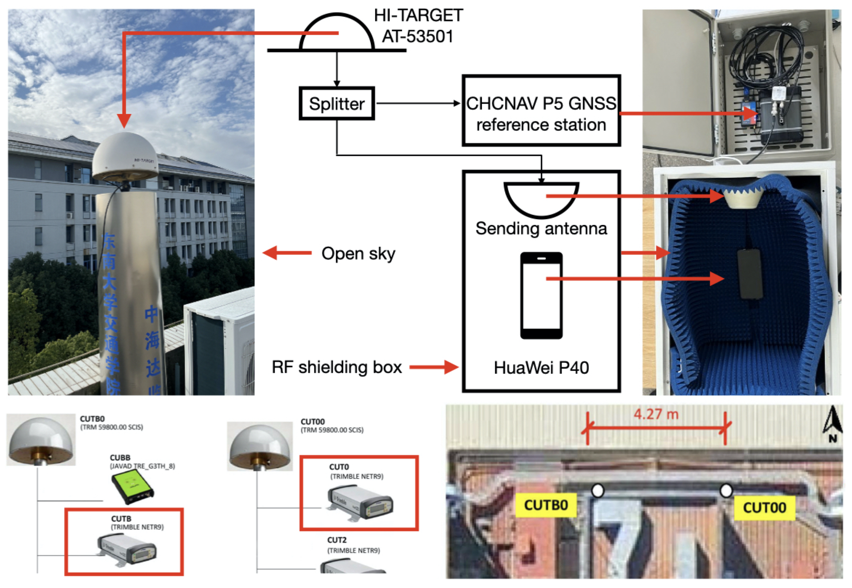
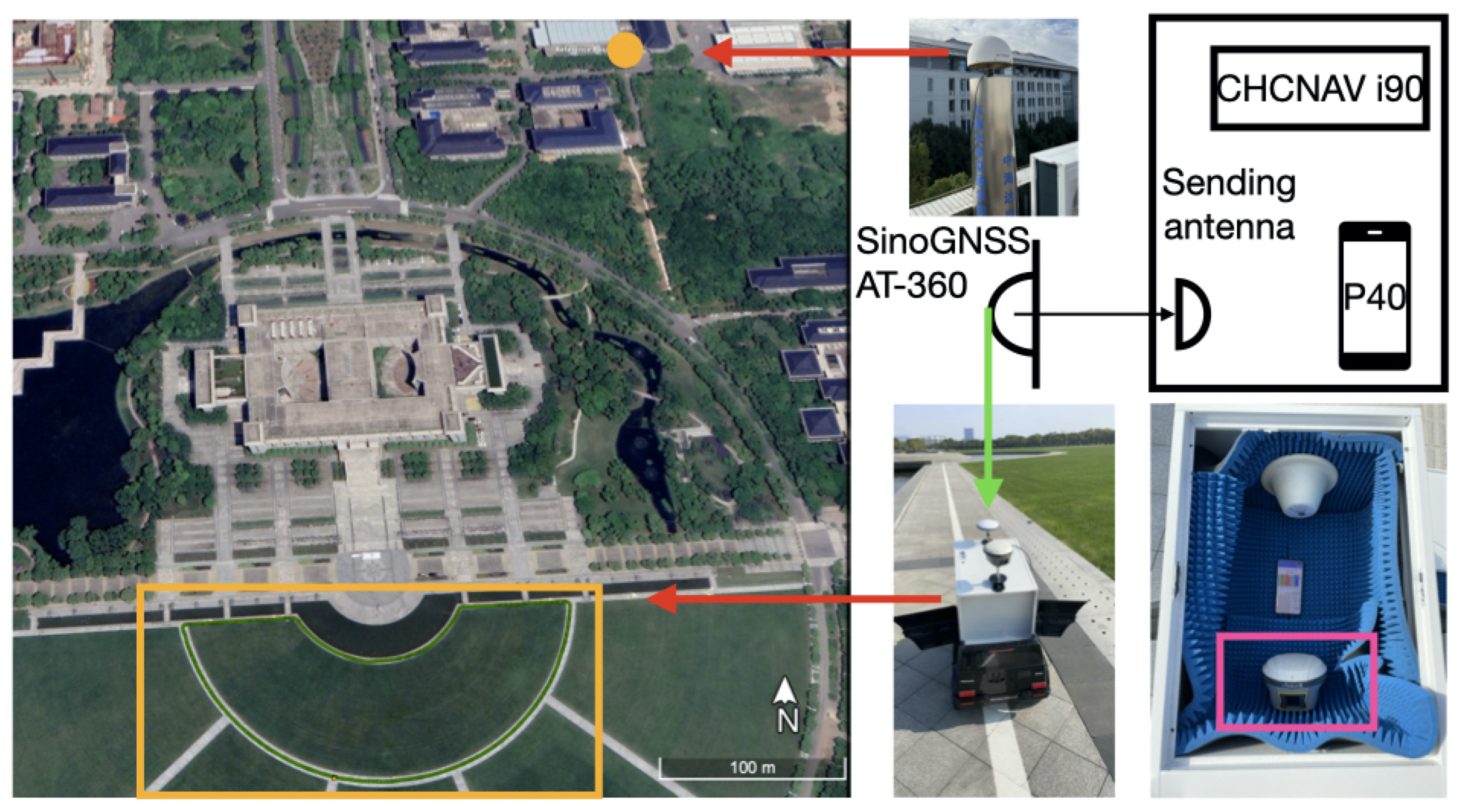
3.1. Experimental Setup and Processing Methods

A zero baseline formed by a smartphone and geodetic receiver was used to study the temporal properties of smartphone receiver channel-dependent bias and DISB. Furthermore, a 4m short-baseline CUT0-CUTB (equipped with both Trimble NetR9 receiver and TRM59800.00 antenna designed by Trimble company) from Curtin GNSS Research Centre was added to compare the receiver channel-dependent bias and DISB characteristics between the smartphone and geodetic receiver. Figure 1 shows the layout of smartphone and base stations for static experiments. As shown in the upper part of Figure 1, the datasets for the zero baseline were collected at Southeast University. A representative HP40 smartphone was used as the rover station, and the JSJN station (one of the Continuously Operating Reference Stations (CORS) of Southeast University) was set as base station. JSJN is composed of the geodetic GNSS receivers CHCNAV P5 (one of the smart GNSS geodetic reference receivers of CHC Navigation company) and a HI-TARGET AT-53501 antenna (one of the 3D choke ring antennas designed by Hi-Target company). To create the zero baseline with JSJN, a signal splitter was used, and the CHCNAV P5 and a sending antenna were connected to two output ports of the splitter. The sending antenna was fixed in a small radio frequency (RF) shielding box, and the HP40 was also placed in the RF shielding box. This experimental method can block the GNSS signals obtained by the antenna of HP40. Meanwhile, we placed the antenna of JSJN on an open roof; thus, these data were not interfered with by multipath signals. Geo++ RINEX (Receiver INdependent EXchange format) Logger (Version 2.1.6) was used to obtain the raw GNSS code and phase data from HP40.
Detailed information and the observation duration of two baselines are presented in Table 1. For JSNJ-HP40, 1h data were collected with sampling rate of 1 s (8:00–9:00, 18 October 2022), and for CUT0-CUTB, 24 h data were collected with sampling rate of 30 s (31 May 2020). From Table 1, we can also see that the code observation on B2a/B3I of HP40 cannot be obtained; thus, only the first frequency observations of all GNSS systems were analyzed in the following experiment. Figure 2 shows the tracked satellites of two baselines with 15 cut-off, and the experimental settings are as follows. Kalman filtering with kinematic positioning mode is used in the experiments, and the commonly used elevation angle-dependent stochastic model was employed [44,45,46]. For AR, the LAMBDA (Least-squares AMBiguity Decorrelation Adjustment) method was adopted to search ambiguity. Furthermore, the threshold for the ratio test was strictly set as 3.0.

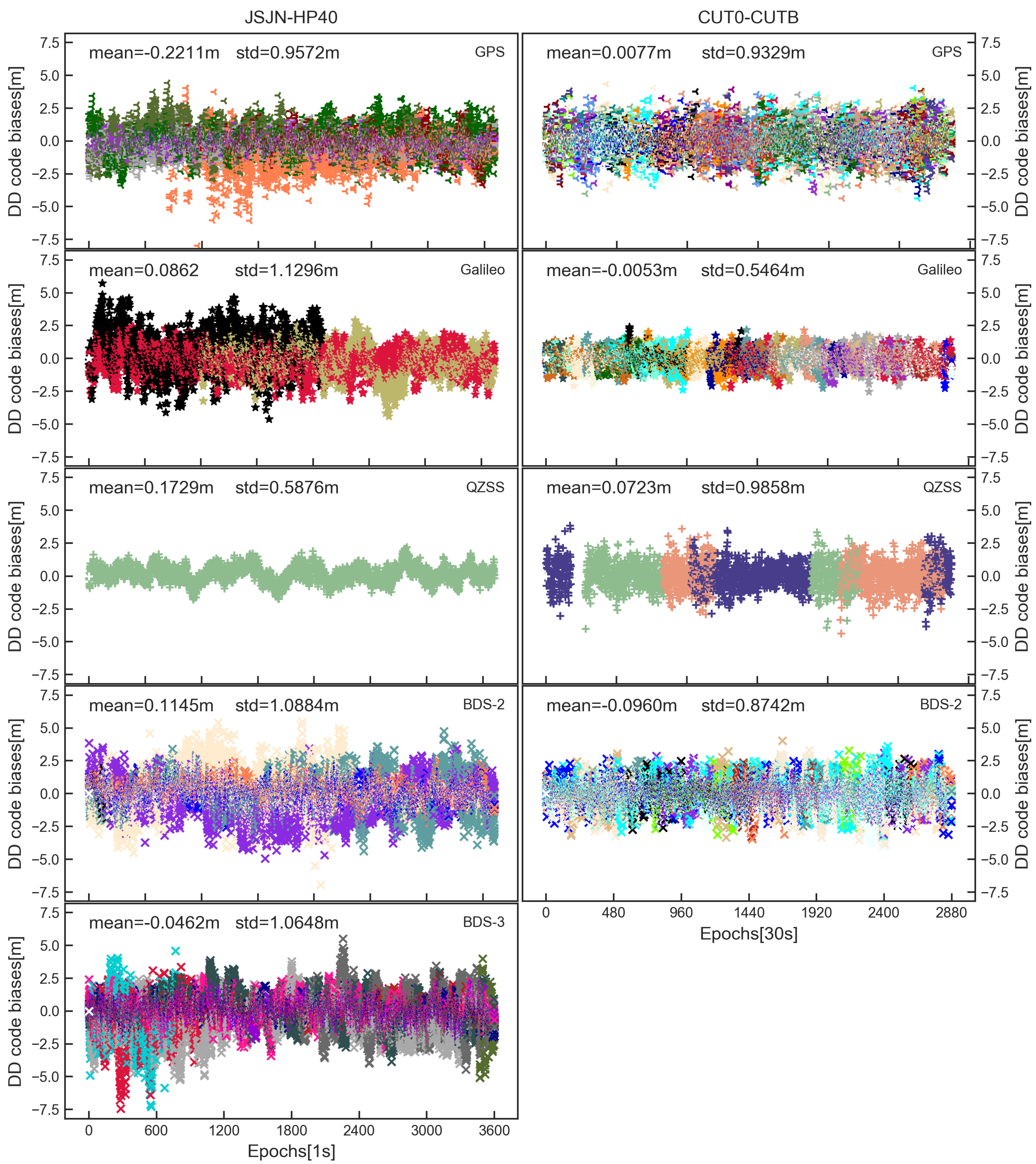
3.2. Temporal Properties of Receiver Channel-Dependent Bias

The DD receiver channel-dependent phase bias estimates of the JSJN-HP40 and CUT0-CUTB are shown in Figure 3. For convenience in analyzing performance of each system, the DD phase bias of GPS/BDS-2/BDS-3/Galileo/QZSS for the JSJN-HP40 is displayed separately. According to Figure 2, the CUT0-CUTB was unable to receive the BDS-3 signals, so only the results of GPS/BDS-2/Galileo/QZSS were analyzed. Furthermore, in each panel, different colors denote different satellite DD phase bias. Based on earlier finds, the DD phase bias of each satellite signals received by geodetic receivers is identical, as shown in the right panel of Figure 3, and the results of CUT0-CUTB show this conclusion as well. In addition, according to the research of Geng et al. [12] and Li et al. [25], for some smartphones, such as XiaoMi Mi8, the receiver channel-dependent phase bias is nonzero and each satellite has a different value. In addition, for Huawei Mate 20, all satellite systems suffer from receiver channel-dependent phase bias, and the offsets differ from satellite systems and frequency bands. These smartphones cannot meet the integer ambiguity resolution (IAR) unless the DD phase bias is handled correctly. Fortunately, it can be seen from the left part of Figure 3 that for HP40, the phase bias of all visible satellites is close to zero. Furthermore, the phase bias standard deviation (STD) of all satellites is basically less than 0.002 cycles, being even smaller than that of the CUT0-CUTB (JSJN-HP40 is a zero baseline, while CUT0-CUTB is a short baseline). We thus demonstrate that the DD IAR of HP40 will not be affected by receiver channel-dependent phase bias. In conclusion, the DISB estimate and inter-system differencing for HP40 can be implemented without worrying about the DD receiver channel-dependent phase bias.
Figure 4 shows the DD code bias estimates of the two baselines; it can be seen that there is obvious systematic fluctuation for the JSJN-HP40. In addition, we carried out GPS L1/Galileo E1 DD code positioning in Figure 5. Again, here we can see the obvious systematic fluctuation in N/E/U directions for the JSJN-HP40, which means that the code observations of HP40 is perhaps strained by the receiver channel-dependent code bias. Furthermore, from Figure 4, we can also see that influenced by smartphone code noise, the STD of the DD code bias of the JSJN-HP40 is greater than CUT0-CUTB. Because the code observations make less of a contribution compared to the phase observations in the RTK positioning, we thus suggested setting a large initial STD value for code observations (such as 0.6m). The receiver channel-dependent code bias can therefore be neglected and their effects will show up in the code residuals [47]. Considering the influence of receiver channel-dependent code bias, during the next sections, we will not describe the code DISB.

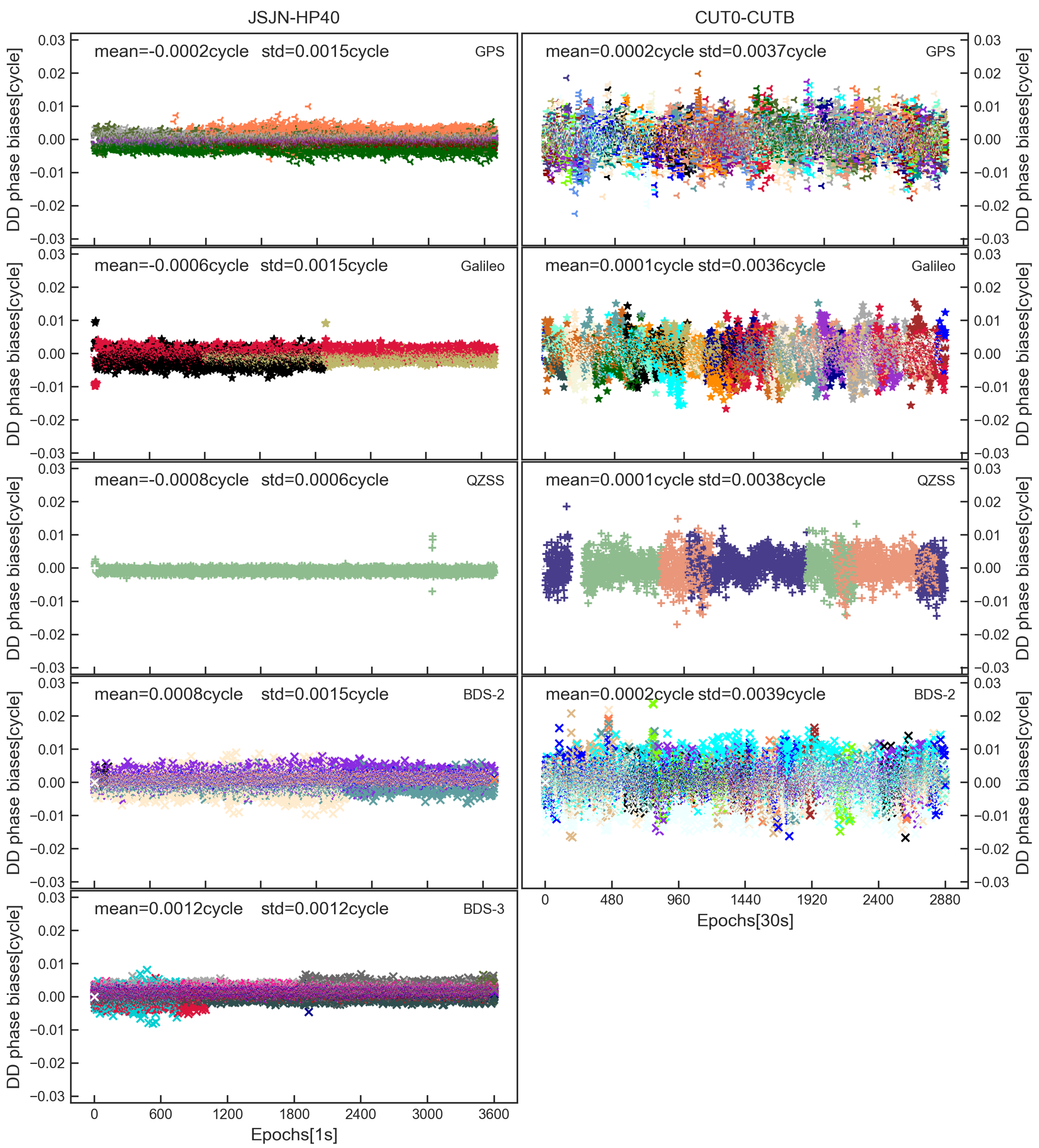
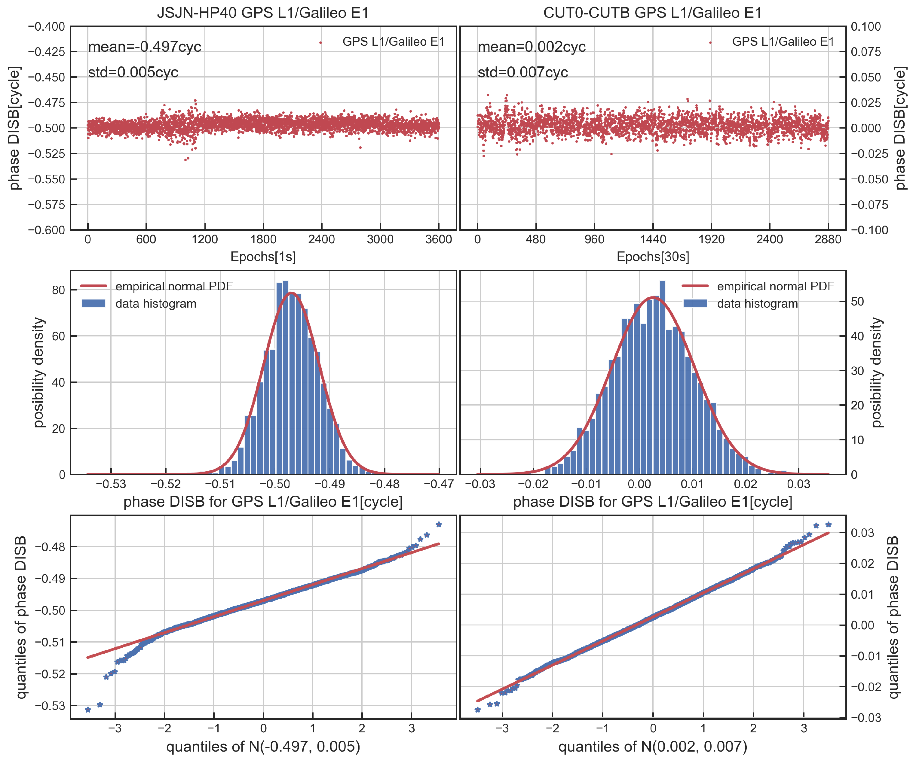
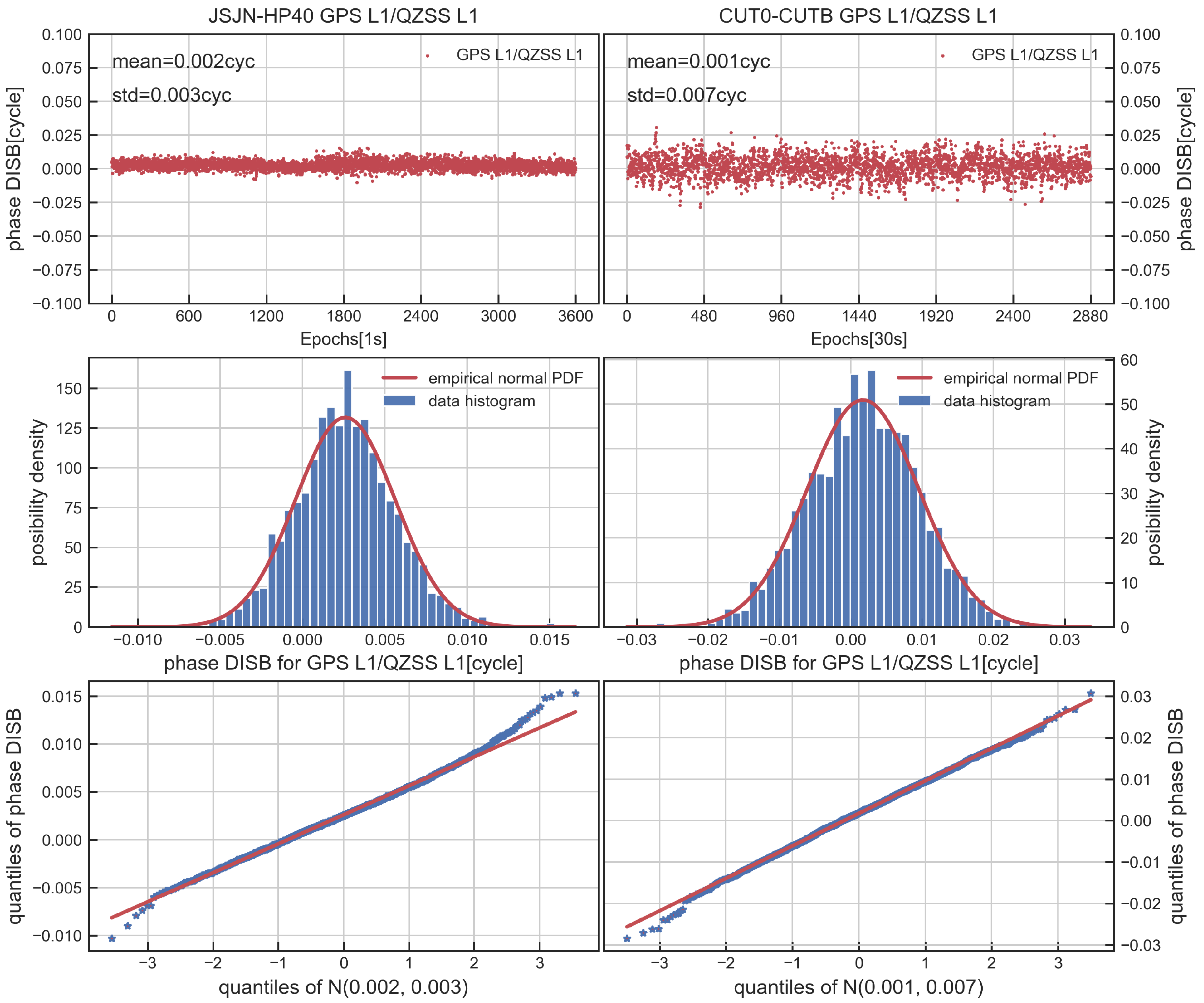
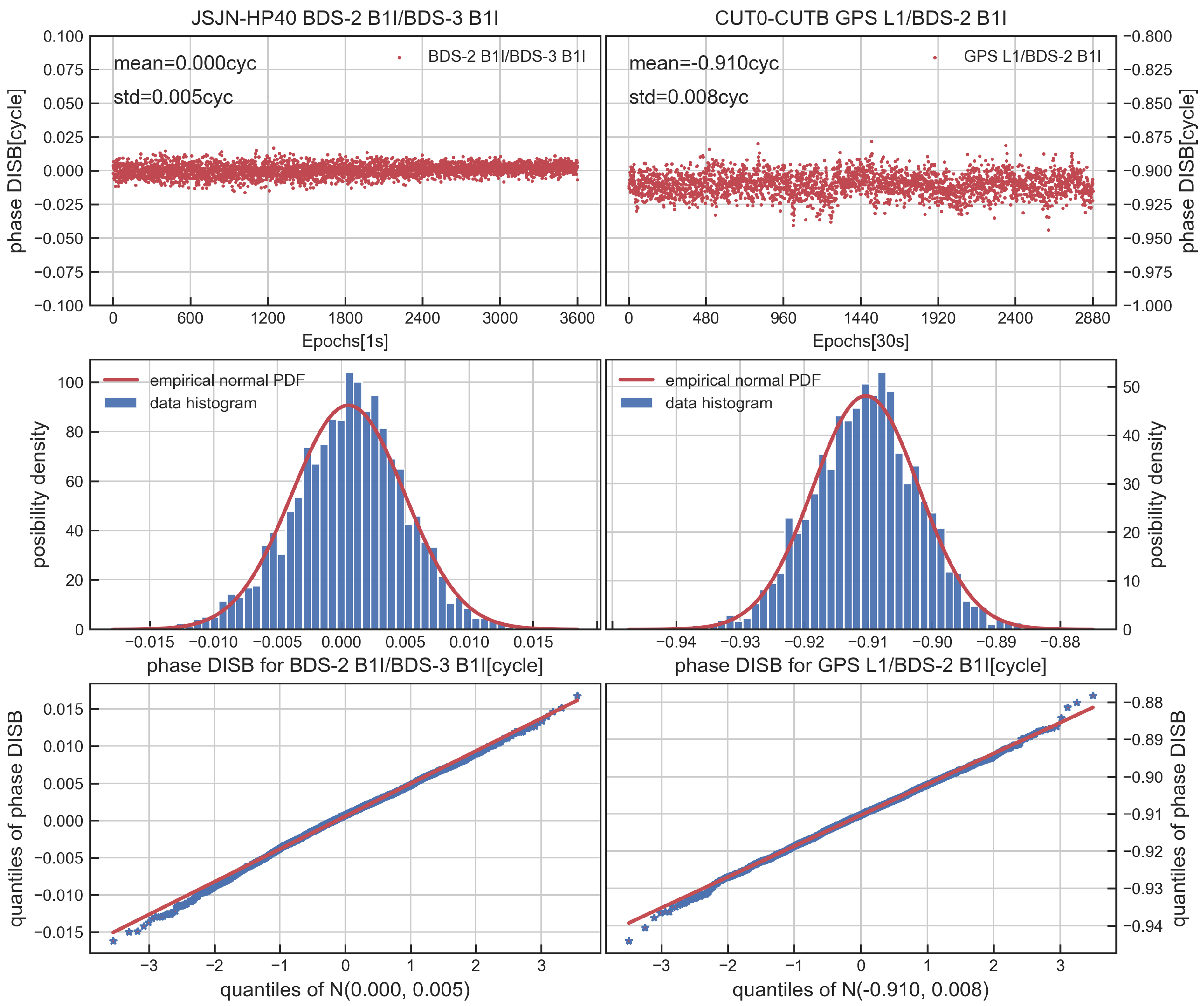
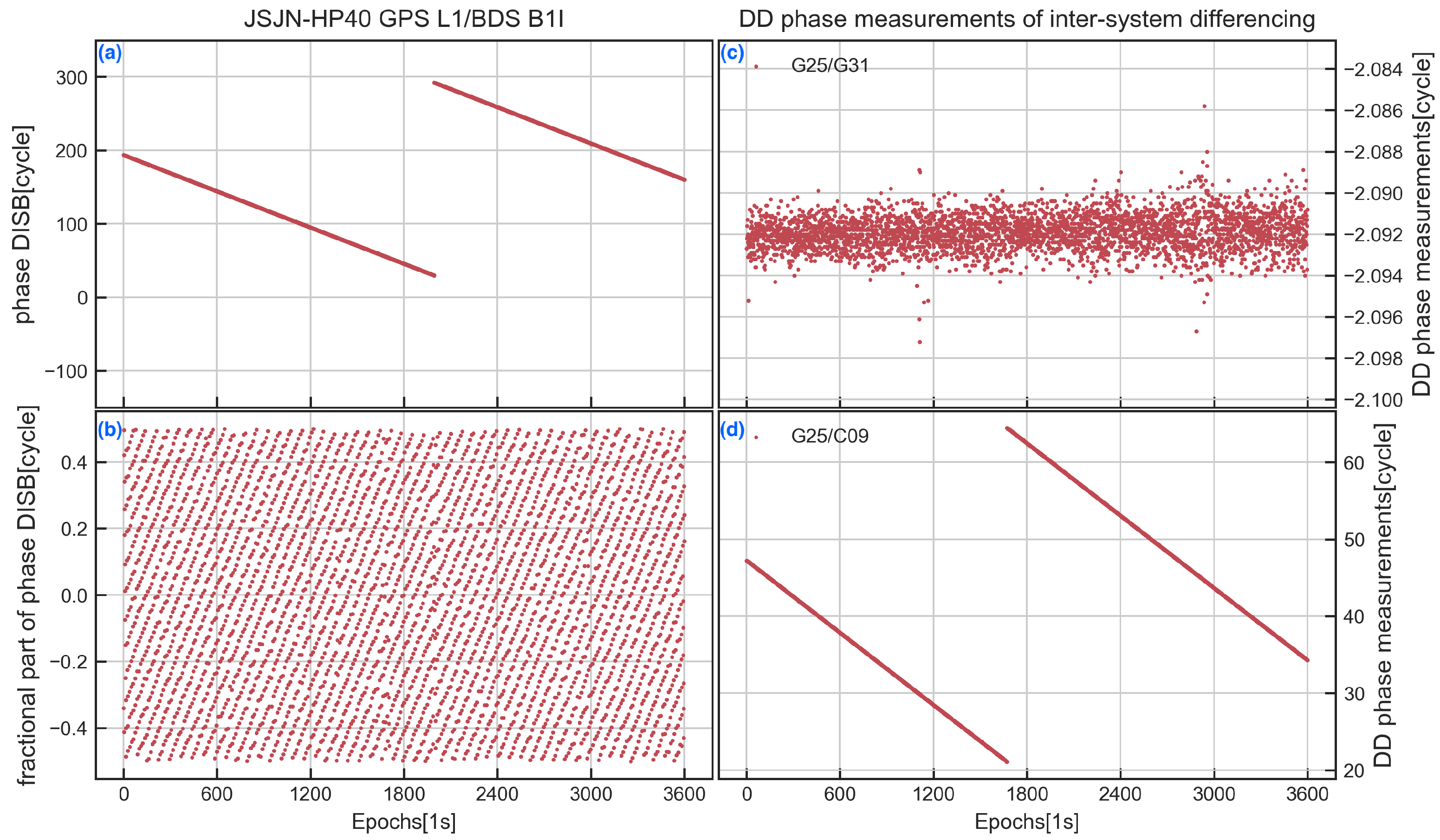
3.3. Temporal Properties of Phase DISB

After analyzing receiver channel-dependent bias, the stability of phase DISB of the CDMA signals, including overlapping frequencies (GPS L1/Galileo E1, GPS L1/QZSS L1, BDS-2 B1I/BDS-3 B1I) and non-overlapping frequencies (GPS L1/BDS-2 B1I), is investigated in the part. The BDS-3 inherits the B1I frequency of BDS-2, and GPS, QZSS and Galileo share the same L1 frequencies, so it is important to research whether DISB is shared between these frequencies to achieve an inter-system model. Furthermore, if the DISB between GPS L1/BDS-2 B1I is also stable, then an inter-system model like that of the geodetic receivers can be realized. The CUT0-CUTB is used as a control group here.
Figure 6, Figure 7 and Figure 8 display the time series, distribution and quantile–quantile (QQ) plot of phase DISB for overlapping frequencies. The results obtained show that the phase DISB of GPS L1/QZSS L1 and BDS-2 B1I/BDS-3 B1I is close to zero, and the STD is within 0.005 cycles for the JSJN-HP40, which is similar to CUT0-CUTB. For GPS L1-Galileo E1, although the phase DISB was nonzero, the STD was within 0.005 cycles, and during the test, it also showed the stable characteristics over time. Furthermore, the distribution of DISB is in accord with the theories perfectly, and the points on the QQ plot are also approximately near a straight line, which shows that the phase DISB is coincident with normal distribution. Table 2 shows the corresponding statistical values and critical value of DISB in the observation period; it can be seen from the table that the phase DISB meets T < χ α 2 ( n 1 , 0 ) , suggesting that the DISB is stable in the observation period.
Figure 9a,b display the integral part and the fractional part of the phase DISB of GPS L1/BDS-2 B1I estimated by the proposed method. It can be seen that the phase DISB of GPS L1/BDS-2 B1I is not stable as the integral part and the fractional part vary for each epoch. To illustrate this, the time series of DD phase measurements for inter-system differencing between GPS L1 and BDS B1I were calculated, and the results of G31 and C09 are shown in Figure 9c,d (both satellites can be continuously observed during the test period, and the G25 was chosen as the reference satellite). In the zero-baseline JSJN-HP40, the DD phase measurements only contain the ambiguity and phase observation noise for GPS intra-system differencing, while GPS L1/ BDS B1I inter-system differencing still includes phase DISB. It can be seen from Figure 9c that the phase data for the GPS is stable as normal, while the DD phase measurements of C09 show the same trends with the phase DISB of GPS L1/BDS B1I; this may be attributable to the GNSS chip hardware design of the HP40. According to previous research for geodetic receivers, the phase DISB for non-overlapping frequencies combination is stable over time. Obviously, the smartphone HP40 does not comply with this law. As a result, the inter-system model is no longer applicable to the HP40 GPS L1/BDS B1I data processing.
Based on the above analysis, for HP40, the inter-system model of GPS L1/QZSS L1 and BDS-2 B1I/BDS-3 B1I can be constructed without considering DISB; the phase DISB for GPS L1/Galileo E1 should be estimated in real time; and the non-overlapping combination of GPS L1/BDS B1I cannot be applied to build an inter-system model.

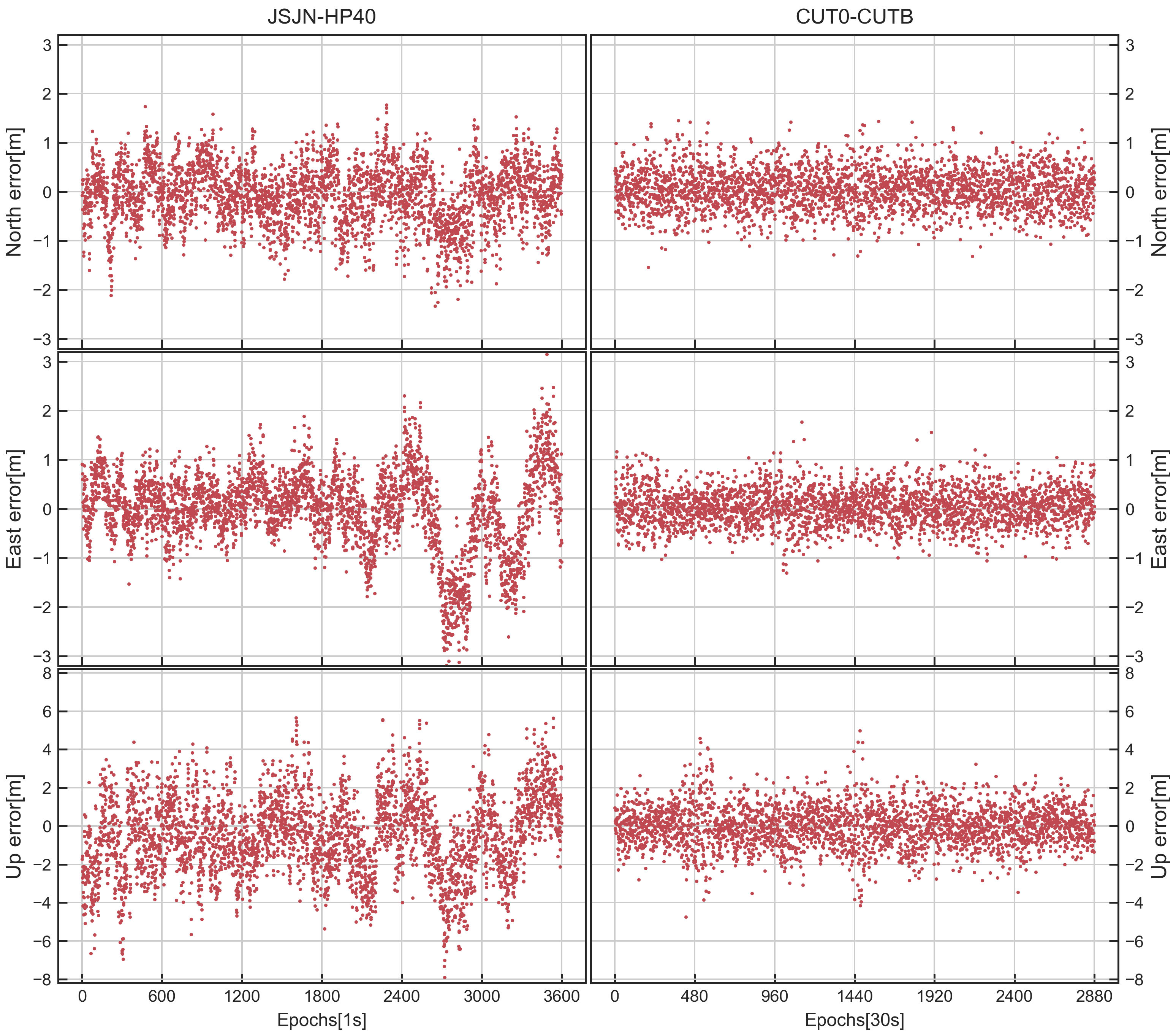
4. Impact of DISB on Kinematic RTK Positioning

The characteristics of the receiver channel-dependent bias and DISB have been researched for the HP40 by using static data. However, in real application, most smartphones are in motion. As conducted in a previous study, the purpose of studying the stability of the DISB is to increase the strength of the positioning model so as to improve the positioning accuracy in real complex situations. In this part, we use a set of kinematics positioning experiments to evaluate the positioning accuracy of the intra-system model and inter-system model.
The kinematic dataset was collected on the lawn in front of the library of Southeast University, as shown in Figure 10, similar to the previous static experiment, and the JSJN station was set as the base station. The HP40 smartphone was used as the rover station and placed in the RF shielding box. The GNSS signals received by the external SinoGNSS AT340 antenna (one of the geodetic antennas of the SinoGNSS company) were sent to the HP40 by a sending antenna, and a CHCNAV i90 GNSS receiver (one of the high-performance IMU-RTK GNSS receivers of the CHC Navigation company) was placed in the RF shielding box for comparison purposes.
In the following positioning experiment, the ambiguity-fixed solutions from the CHCNAV i90 GNSS receiver are used as the true values to evaluate the solutions of the smartphone. A remote-control kart with a maximum speed of 6 km/h is used as a carrier to place these devices, and Figure 11 shows the real-time motion speed of the kart. Table 3 presents the experiment details; the dynamic baseline length was 0.4~0.6 km, and 25 min of data were collected with a sampling rate of 1s. Note that the L1/E1 frequency is used by GPS and Galileo and that there is a phase DISB between them; so, in the following experiment, we estimated the phase DISB in real time to build the inter-system model. In order to compare the positioning performance of the intra-system and inter-system models in a complex environment, we evaluated the positioning results of the two models when the cut-off angle was set to 35 .
At first, only the GPS + 2 Galileo is used, and then the Galileo satellites are gradually added according to the elevation angle. Table 4 presents the AR results in terms of the empirical success rates (the proportion of the number of ambiguity-fixed epochs relative to the number of total epochs) and the TTFF (time to first fix). Table 5 presents the statistics of the positioning results for the intra-system model and inter-system model. Figure 12(top,bottom) show the horizontal and vertical position error distributions using the intra- system and the inter-system model for two different combinations (GPS + 3 Galileo and GPS + 4 Galileo) with a cut-off angle of 35 .
The results show that the inter-system model can improve the positioning accuracy when only small satellites are used for positioning. For the case of GPS + two Galileo, the success rate increases to 82.9% for the intra-system model compared with 90.4% for the inter-system model, and the TTFF of the inter-system model is also shorter than the intra-system model. In addition, the positioning accuracies can increase about 8.9%, 30.6% and 38.9% in three directions. Furthermore, from the red box of Figure 12(top), we can see that only the inter-system model can obtain the fixed solution. With the ambiguities fixed, the positioning accuracy for the intra-system model and inter-system model are smaller than 5 cm, which means that the HP40 can achieve centimeter-level positioning, and when all the GPS and five Galileo satellites are used, both the inter-system model and intra-system model can achieve a high positioning performance. In conclusion, after correcting the phase DISB, the positioning performance of the inter-system model improved significantly, showing that centimeter-level positioning can be achieved in a complex environment for the HP40 with an external antenna. Therefore, using the inter-system model to improve the GNSS positioning performance in a complex observation environment for smartphones has important theoretical and practical significance. This approach will provide important support for the informatization of emerging industries, such as smart cities and intelligent transportation.

5. Discussion

The opening of the GNSS data interface of smartphones and the development of chips provide great opportunities for high-precision navigation for the public, but at the same time, the high-precision positioning of smartphones in urban environments still faces great challenges. In a relatively open observation environment, smartphones can also achieve a high positioning accuracy similar to a geodetic receiver. However, in the complex observation environment (such as the urban canyon with densely packed buildings), due to the characteristics of the GNSS signal transmission, the accuracy and reliability of the GNSS positioning still face great challenges, which are mainly reflected in the insufficient number of visible satellites, the weak intensity of the satellite geometric observation and the poor quality of the observation signals. The compatibility and interoperability of a GNSS multi-system can improve the positioning accuracy in complex environments to a certain extent, especially when there are few observation satellites.
For smartphone GNSS positioning, the receiver channel-dependent bias should be corrected in advance to achieve inter-system differencing positioning. After that, as shown in previous sections, for the HP40, the phase DISB between GPS L1/QZSS L1 and BDS-2 B1I/BDS-3 B1I is zero, and for GPS L1/Galileo E1, although the DISB is nonzero, it is stable. These stable DISB values can be used to strengthen the positioning model. However, we should also note that the phase DISB of GPS L1/BDS B1I is unstable, which is different with geodetic receivers. In view of the above problem, it is necessary to further study a more universal parameter estimation method so as to establish the inter-system processing method suitable for non-overlapping frequencies observations. The kinematic positioning experiment demonstrates that the inter-system model for a smartphone can effectively improve the positioning performance under complex environments. Although the inter-system differencing experiments performed were based on static or low dynamics, we think they can also be similarly carried out in a real-time, high-dynamic kinematic case, as long as the DISB is verified to be stable.

6. Conclusions

In this paper, we investigated the inter-system differencing between CDMA systems for smartphones. The DD receiver channel-dependent bias and DISB were assessed by using static datasets, and a real kinematic experiment was designed to assess the positioning performance of the inter-system model. The research findings of this contribution are as follows.
(1) For the HP40, the receiver channel-dependent phase biases are close to zero and show time-domain stability, and the STD of the receiver channel-dependent phase bias of all the satellites is less than 0.002 cycles, which provides the possibility of phase DISB estimation between frequency signals. However, there is an obvious systematic fluctuation for the DD code biases of the JSJN-HP40, which means that the HP40 is affected by the receiver channel-dependent code bias. We thus suggested setting a large initial STD value for code observations in the positioning to avoid the effect of the receiver channel-dependent code bias.
(2) The phase DISB of GPS L1/QZSS L1 and BDS-2 B1I/BDS-3 B1I is close to zero, and the STD is within 0.003 cycles for the HP40. For GPS L1/Galileo E1, although the phase DISB is nonzero, the STD is within 0.005 cycles, and during the test, it also showed stable characteristics over time. However, the phase DISB of GPS L1/BDS B1I is not stable.
(3) After introducing the stable phase DISB into the inter-system model, as expected, the kinematic positioning performance of the multi-GNSS RTK resulted in a 3–38.9% improvement in the positioning accuracies for complex environments, compared with the intra-system model, and the success rate was also improved and the TTFF was shortened.

Author Contributions

Conceptualization, R.S. and C.G.; methodology, R.S.; software, R.S. and R.Z.; validation, R.S.; formal analysis, R.S.; investigation, R.S.; resources, R.S. and L.G.; data curation, C.G. and R.S.; writing—original draft preparation, R.S; writing—review and editing, C.G., R.S., X.M. and W.G.; visualization, R.S., L.G. and R.Z.; supervision, C.G. and R.S.; project administration, C.G., R.S. and W.G.; funding acquisition, C.G., R.S. and X.M. All authors have read and agreed to the published version of the manuscript.

Funding

This research was funded by the Outstanding Postdoctoral Program of Jiangsu Province in 2022 (2022ZB113), the National Natural Science Foundation of China (41904022, 41974030) and the Ministry of Education-China Mobile Research Fund (MCM20200J01).

Data Availability Statement

The data that support the findings of this study are available on request from the corresponding author, upon reasonable request.

Acknowledgments

The authors gratefully acknowledge the GNSS Research Centre of Curtin University for providing the multi-GNSS observation data. Thanks also go to Li Guangcai for his support in the data acquisition. Valuable comments from the anonymous reviewers are acknowledged as well.

Conflicts of Interest

The authors declare no conflict of interest.

References

  1. Zhang, B.; Hou, P.; Zha, J.; Liu, T. PPP–RTK functional models formulated with undifferenced and uncombined GNSS observations. Satell. Navig. 2022, 3, 3. [Google Scholar] [CrossRef]
  2. Zhang, Z.; Yuan, H.; He, X.; Li, B.; Geng, J. Best Integer Equivariant Estimation With Quality Control in GNSS RTK for Canyon Environments. IEEE Trans. Aerosp. Electron. Syst. 2023, 1–15. [Google Scholar] [CrossRef]
  3. Ye, J. Research on Pedestrian Navigation Algorithm Based on Multi-Sensor Fusion; Chang’an University: Xi’an, China, 2020. [Google Scholar]
  4. Ge, Y.; Cao, X.; Lyu, D.; He, Z.; Ye, F.; Xiao, G.; Shen, F. An investigation of PPP time transfer via BDS-3 PPP-B2b service. GPS Solut. 2023, 27, 61. [Google Scholar] [CrossRef]
  5. Sikirica, N.; Malić, E.; Rumora, I.; Filjar, R. Exploitation of Google GNSS measurement API for risk assessment of GNSS applications. In Proceedings of the 2017 25th Telecommunication Forum (TELFOR), Belgrade, Serbia, 21–22 November 2017; pp. 1–3. [Google Scholar]
  6. Banville, S.; Van Diggelen, F. Precise positioning using raw GPS measurements from Android smartphones. GPS World 2016, 27, 43–48. [Google Scholar]
  7. Chen, B.; Gao, C.; Liu, Y.; Sun, P. Real-time precise point positioning with a Xiaomi MI 8 android smartphone. Sensors 2019, 19, 2835. [Google Scholar] [CrossRef] [Green Version]
  8. Bahadur, B. A study on the real-time code-based GNSS positioning with Android smartphones. Measurement 2022, 194, 111078. [Google Scholar] [CrossRef]
  9. Li, Z.; Wang, L.; Wang, N.; Li, R.; Liu, A. Real-time GNSS precise point positioning with smartphones for vehicle navigation. Satell. Navig. 2022, 3, 19. [Google Scholar] [CrossRef]
  10. Li, G.; Geng, J. Characteristics of raw multi-GNSS measurement error from Google Android smart devices. GPS Solut. 2019, 23, 90. [Google Scholar] [CrossRef]
  11. Zhang, Z.; Li, B.; Gao, Y.; Shen, Y. Real-time carrier phase multipath detection based on dual-frequency C/N0 data. GPS Solut. 2019, 23, 7. [Google Scholar] [CrossRef]
  12. Geng, J.; Li, G. On the feasibility of resolving Android GNSS carrier-phase ambiguities. J. Geod. 2019, 93, 2621–2635. [Google Scholar] [CrossRef]
  13. Darugna, F.; Wübbena, J.; Ito, A.; Wübbena, T.; Wübbena, G.; Schmitz, M. RTK and PPP-RTK using smartphones: From short-baseline to long-baseline applications. In Proceedings of the 32nd International Technical Meeting of the Satellite Division of The Institute of Navigation (ION GNSS+ 2019), Miami, FL, USA, 16–20 September 2019; pp. 3932–3945. [Google Scholar]
  14. Bochkati, M.; Sharma, H.; Lichtenberger, C.A.; Pany, T. Demonstration of fused RTK (fixed)+ inertial positioning using Android smartphone sensors only. In Proceedings of the 2020 IEEE/ION Position, Location and Navigation Symposium (PLANS), Portland, OR, USA, 20–23 April 2020; pp. 1140–1154. [Google Scholar]
  15. Sun, R.; Wang, J.; Cheng, Q.; Mao, Y.; Ochieng, W.Y. A new IMU-aided multiple GNSS fault detection and exclusion algorithm for integrated navigation in urban environments. GPS Solut. 2021, 25, 147. [Google Scholar] [CrossRef]
  16. Liu, Q.; Gao, C.; Shang, R.; Peng, Z.; Zhang, R.; Gan, L.; Gao, W. NLOS signal detection and correction for smartphone using convolutional neural network and variational mode decomposition in urban environment. GPS Solut. 2023, 27, 31. [Google Scholar] [CrossRef]
  17. Xia, Y.; Pan, S.; Meng, X.; Gao, W.; Ye, F.; Zhao, Q.; Zhao, X. Anomaly detection for urban vehicle GNSS observation with a hybrid machine learning system. Remote Sens. 2020, 12, 971. [Google Scholar] [CrossRef] [Green Version]
  18. Xia, Y.; Meng, X.; Yang, Y.; Pan, S.; Zhao, Q.; Gao, W. First results of BDS positioning for LBS applications in the UK. Satell. Navig. 2021, 2, 8. [Google Scholar] [CrossRef]
  19. Humphreys, T.E.; Murrian, M.; Van Diggelen, F.; Podshivalov, S.; Pesyna, K.M. On the feasibility of cm-accurate positioning via a smartphone’s antenna and GNSS chip. In Proceedings of the 2016 IEEE/ION Position, Location and Navigation Symposium (PLANS), Savannah, GR, USA, 11–14 April 2016; pp. 232–242. [Google Scholar]
  20. Riley, S.; Lentz, W.; Clare, A. On the path to precision-observations with android GNSS observables. In Proceedings of the 30th International Technical Meeting of The Satellite Division of The Institute of Navigation (ION GNSS+ 2017), Portland, OR, USA, 25–29 September 2017; pp. 116–129. [Google Scholar]
  21. Paziewski, J.; Sieradzki, R.; Baryla, R. Signal characterization and assessment of code GNSS positioning with low-power consumption smartphones. GPS Solut. 2019, 23, 98. [Google Scholar] [CrossRef] [Green Version]
  22. Paziewski, J. Recent advances and perspectives for positioning and applications with smartphone GNSS observations. Meas. Sci. Technol. 2020, 31, 091001. [Google Scholar] [CrossRef]
  23. Paziewski, J.; Fortunato, M.; Mazzoni, A.; Odolinski, R. An analysis of multi-GNSS observations tracked by recent Android smartphones and smartphone-only relative positioning results. Measurement 2021, 175, 109162. [Google Scholar] [CrossRef]
  24. Li, G.; Geng, J. Android multi-GNSS ambiguity resolution in the case of receiver channel-dependent phase biases. J. Geod. 2022, 96, 72. [Google Scholar] [CrossRef]
  25. Li, B.; Miao, W.; Chen, G.; Li, Z. Ambiguity resolution for smartphone GNSS precise positioning: Effect factors and performance. J. Geod. 2022, 96, 63. [Google Scholar] [CrossRef]
  26. Julien, O.; Alves, P.; Cannon, M.E.; Zhang, W. A tightly coupled GPS/GALILEO combination for improved ambiguity resolution. In Proceedings of the European Navigation Conference (ENC-GNSS’03), Calgary, AB, Canada, 9 September 2003; pp. 1–14. [Google Scholar]
  27. Zhang, B.; Teunissen, P.J.; Yuan, Y. On the short-term temporal variations of GNSS receiver differential phase biases. J. Geod. 2017, 91, 563–572. [Google Scholar] [CrossRef] [Green Version]
  28. Montenbruck, O.; Hauschild, A.; Steigenberger, P. Differential code bias estimation using multi-GNSS observations and global ionosphere maps. Navig. J. Inst. Navig. 2014, 61, 191–201. [Google Scholar] [CrossRef]
  29. Odijk, D.; Teunissen, P.J. Characterization of between-receiver GPS-Galileo inter-system biases and their effect on mixed ambiguity resolution. GPS Solut. 2013, 17, 521–533. [Google Scholar] [CrossRef]
  30. Paziewski, J.; Wielgosz, P. Accounting for Galileo–GPS inter-system biases in precise satellite positioning. J. Geod. 2015, 89, 81–93. [Google Scholar] [CrossRef] [Green Version]
  31. Nadarajah, N.; Khodabandeh, A.; Teunissen, P.J. Assessing the IRNSS L5-signal in combination with GPS, Galileo, and QZSS L5/E5a-signals for positioning and navigation. GPS Solut. 2016, 20, 289–297. [Google Scholar] [CrossRef]
  32. Odijk, D.; Nadarajah, N.; Zaminpardaz, S.; Teunissen, P.J. GPS, Galileo, QZSS and IRNSS differential ISBs: Estimation and application. GPS Solut. 2017, 21, 439–450. [Google Scholar] [CrossRef]
  33. Odolinski, R.; Teunissen, P.J. Single-frequency, dual-GNSS versus dual-frequency, single-GNSS: A low-cost and high-grade receivers GPS-BDS RTK analysis. J. Geod. 2016, 90, 1255–1278. [Google Scholar] [CrossRef]
  34. Wu, M.; Liu, W.; Wang, W.; Zhang, X. Differential inter-system biases estimation and initial assessment of instantaneous tightly combined RTK with BDS-3, GPS, and Galileo. Remote Sens. 2019, 11, 1430. [Google Scholar] [CrossRef] [Green Version]
  35. Yuan, H.; Zhang, Z.; He, X.; Zeng, J. Tight integration of BDS-3/BDS-2/GPS/Galileo observations considering the new overlapping DISBs and its application in obstructed environments. Adv. Space Res. 2022, 71, 2879–2891. [Google Scholar] [CrossRef]
  36. Gao, W.; Meng, X.; Gao, C.; Pan, S.; Wang, D. Combined GPS and BDS for single-frequency continuous RTK positioning through real-time estimation of differential inter-system biases. GPS Solut. 2018, 22, 20. [Google Scholar] [CrossRef]
  37. Mi, X.; Zhang, B.; Yuan, Y.; Luo, X. Characteristics of GPS, BDS2, BDS3 and Galileo inter-system biases and their influence on RTK positioning. Meas. Sci. Technol. 2019, 31, 015009. [Google Scholar] [CrossRef]
  38. Mi, X.; Zhang, B.; Yuan, Y. Multi-GNSS inter-system biases: Estimability analysis and impact on RTK positioning. GPS Solut. 2019, 23, 81. [Google Scholar] [CrossRef]
  39. Chen, H.; Jiang, W.; Li, J. Multi-GNSS relative positioning with fixed inter-system ambiguity. Remote Sens. 2019, 11, 454. [Google Scholar] [CrossRef] [Green Version]
  40. Shang, R.; Meng, X.; Gao, C.; Pan, S.; Gao, W.; Peng, Z. Particle filter-based inter-system positioning model for non-overlapping frequency code division multiple access systems. J. Navig. 2020, 73, 953–970. [Google Scholar] [CrossRef]
  41. Liu, J.; Tu, R.; Han, J.; Zhang, R.; Zhang, P.; Fan, L. Estimability analysis of differential inter-system biases and differential inter-frequency biases for dual-frequency GPS and BDS combined RTK. Meas. Sci. Technol. 2019, 31, 025009. [Google Scholar] [CrossRef]
  42. Zhang, B.; Teunissen, P. Zero-baseline Analysis of GPS/BeiDou/Galileo Between-Receiver Differential Code Biases (BR-DCBs): Time-wise Retrieval and Preliminary Characterization. Navig. J. Inst. Navig. 2016, 63, 181–191. [Google Scholar] [CrossRef] [Green Version]
  43. Xiaohong, Z.; Mingkui, W.; Wanke, L. Model and Performance Analysis of Tightly Combined BeiDou B2 and Galileo E5b Relative Positioning for Short Baseline. Acta Geod. Et Cartogr. Sin. 2017, 45, 1. [Google Scholar]
  44. Zhang, Z.; Li, Y.; He, X.; Chen, W.; Li, B. A composite stochastic model considering the terrain topography for real-time GNSS monitoring in canyon environments. J. Geod. 2022, 96, 79. [Google Scholar] [CrossRef]
  45. Sui, M.; Gong, C.; Shen, F. An optimized stochastic model for smartphone GNSS positioning. Front. Earth Sci. 2022, 10, 1018420. [Google Scholar] [CrossRef]
  46. Yuan, H.; Zhang, Z.; He, X.; Li, G.; Wang, S. Stochastic model assessment of low-cost devices considering the impacts of multipath effects and atmospheric delays. Measurement 2022, 188, 110619. [Google Scholar] [CrossRef]
  47. Cai, C.; Gao, Y. Modeling and assessment of combined GPS/GLONASS precise point positioning. GPS Solut. 2013, 17, 223–236. [Google Scholar] [CrossRef]
Figure 1. Layout of the smartphone and receiver for two static baselines.
Remotesensing 15 01476 g001
Figure 2. Total number of tracked GPS/BDS-2/BDS-3/Galileo/QZSS satellites for the two static baselines datasets.
Remotesensing 15 01476 g002
Figure 3. The DD receiver channel−dependent phase bias (cycle) of different systems and satellites for JSJN−HP40 and CUT0−CUTB.
Remotesensing 15 01476 g003
Figure 4. The DD receiver channel−dependent code bias (m) of different systems and satellites for JSJN−HP40 and CUT0−CUTB.
Remotesensing 15 01476 g004
Figure 5. The time series of DD code positioning errors for JSJN−HP40 (left) and CUT0−CUTB (right).
Remotesensing 15 01476 g005
Figure 6. Time series, distribution and QQ plot of GPS L1/Galileo E1 phase DISB for JSJN−HP40 (left) and CUT0−CUTB (right).
Remotesensing 15 01476 g006
Figure 7. Time series, distribution and QQ plot of GPS L1/QZSS L1 phase DISB for JSJN−HP40 (left) and CUT0−CUTB (right).
Remotesensing 15 01476 g007
Figure 8. Time series, distribution and QQ plot of BDS−2 B1I/BDS−3 B1I phase DISB for JSJN−HP40 (left) and GPS L1/BDS−2 B1I phase DISB for CUT0−CUTB (right).
Remotesensing 15 01476 g008
Figure 9. Time series of integral part (a) and the fractional part (b) of the phase DISB of GPS L1/BDS−2 B1I, and the DD phase measurements of G25/G31 (c) and G25/C09 (d).
Remotesensing 15 01476 g009
Figure 10. Layout of the smartphone and receiver for collecting kinematic datasets.
Remotesensing 15 01476 g010
Figure 11. The velocity of remote−control kart for kinematic experiments.
Remotesensing 15 01476 g011
Figure 12. Horizontal position scatter and corresponding vertical time series for the intra−system model (red dots) and the inter−system model (blue dots) for the case of GPS + 3 Galileo (top) and GPS + 4 Galileo (bottom).
Remotesensing 15 01476 g012
Table 1. The information and details of static datasets.
BaselineDeviceAntennaDuration (UTC Time)Systems and Frequencies
LP
JSJN-HP40CHCNAV P5 (base)HI-TARGET AT-535011 h (08:00–09:00,
18 December 2022)
G:L1/L5; E:E1/E5a;
C:B1I B1C B2a;
J:L1/L5
G:L1/L5; E:E1/E5a;
C:B1I; J:L1/L5
HP40 (rover)Embedded antennaG:L1/L5; E:E1/E5a;
C:B1I B1C B2a;
J:L1/L5
G:L1/L5; E:E1/E5a;
C:B1I B1C B2a;
J:L1/L5
CUT0-CUTBTrimble NetR9 (base)TRM59800.0024 h
(31 May 2020)
G:L1/L5; E:E1/E5a;
C:B1I B1C B2a;
J:L1/L5
G:L1/L5; E:E1/E5a;
C:B1I B1C B2a;
J:L1/L5
Trimble NetR9 (rover)TRM59800.00G:L1/L5; E:E1/E5a;
C:B1I B1C B2a;
J:L1/L5
G:L1/L5; E:E1/E5a;
C:B1I B1C B2a;
J:L1/L5
Table 2. Test statistics and critical value for phase DISB.
BaselinePhase CombinationT χ α 2 ( n 1 , 0 )
JSJN-HP40GPS L1/Galileo E1471.13740.7
GPS L1/QZSS L1102.83740.7
BDS-2 B1I/BDS-3 B1I106.93740.7
CUT0-CUTBGPS L1/Galileo E1368.43006.0
GPS L1/QZSS L1261.43006.0
GPS L1/BDS-2 B1I745.13006.0
Table 3. Observation information for kinematic test.
Base ReceiverRover DeviceAntennaBaseline LengthDuration (UTC Time)
JSJNHP40SinoGNSS
AT340
0.4–0.6 km25 min (03:35–04:00,
13 December 2022)
CHCNAV i90
Table 4. Empirical IAR success rates and TTFF for kinematic experiments.
CaseFix Rate (%)TTFF (s)
IntraInterIntraInter
GPS + 2 Galileo82.990.44525
GPS + 3 Galileo95.399.51611
GPS + 4 Galileo99.299.6125
GPS + 5 Galileo99.399.695
Table 5. Positioning comparison for the intra-system model and the inter-system model with different cases.
CasePositioning Accuracy (cm)Improvement (%)
IntraInter
NEUNEUNEU
GPS + 2 Galileo0.370.371.800.330.261.108.930.638.9
GPS + 3 Galileo0.340.281.170.320.251.055.510.310.2
GPS + 4 Galileo0.310.251.030.300.240.944.76.59.3
GPS + 5 Galileo0.310.240.890.300.240.853.32.54.9
Disclaimer/Publisher’s Note: The statements, opinions and data contained in all publications are solely those of the individual author(s) and contributor(s) and not of MDPI and/or the editor(s). MDPI and/or the editor(s) disclaim responsibility for any injury to people or property resulting from any ideas, methods, instructions or products referred to in the content.

