Abstract
Long-runout landslides occur frequently in the sandstone and mudstone mountainous areas in southwestern China under heavy rainfall conditions. This has been a key issue in the field of disaster prevention and reduction. Considering the Niuerwan landslide in Wulong, Chongqing, on 13 July 2020, as an example, we employed technical methodologies, including unmanned aerial vehicle (UAV) images, field investigation, geological condition analysis (including geomorphology and topography, stratigraphic structure and formation lithology, etc.), interferometric synthetic aperture radar (InSAR) monitoring and Particle Flow Code 3D (PFC3D) simulations to study failure mechanism and a long-runout motion model of flow-like landslides induced by the heavy rainfall. The results showed that (1) the large differences between the upper and lower strata are the root cause of the instability and long-runout fluidization movement; (2) heavy rainfall is the key driving factor of slope instability and deep-seated landslides, leading to long-distance movement of the upper saturated residual soil; (3) the long-runout fluidization model of bedding landslides is mainly divided into the overall sliding in the lower layer, the mixing of coarse and fine particles in the middle layer, and saturation fluidization in the upper layer; and (4) the long-runout fluidization process of bedding landslides is composed of three stages: overall instability, mixed acceleration, and fluidization accumulation. In view of these findings, in the risk evaluation and prediction of long-runout fluidization landslides in sandstone and mudstone mountainous areas, this particular disaster model can be used to provide quantitative references for disaster prevention and mitigation.
1. Introduction
Global warming has a strong impact on the occurrence of extreme weather events (e.g., heavy rainfall, high temperature, strong wind, and flooding) and increases the risk of geological disasters []. In particular, high-level long-runout landslides under heavy rainfall conditions occur frequently and pose a great threat to the safety of human life and property. High-level long-runout landslides are a type of landslide that is cut out from high and steep slopes and fall at an accelerated rate. They often have large potential energy, are easily converted into debris flows or debris avalanches during their movement, and have huge destructive capabilities [,,,,]. In the mountainous areas of sandstone and mudstone formations in southwestern China, heavy rainfall has caused a number of high-level long-runout geological disasters. For example, in September 2014, a heavy rainfall event occurred in Northeast Chongqing and led to long-runout landslides in many nearby areas [], including the Wushanping landslide in Fengjie, the Xianchi Reservoir landslide, and the Baiguozhai landslide. Many studies have been carried out to study the hazard model and movement mechanism of heavy rainfall-induced landslides. It is believed that rainwater infiltration increases the weight of the landslide mass and the pore water pressure, which are the key factors causing instability [,,,,,,,,,]. Kinetic energy retention and base frictional resistance are two essential factors affecting the long-distance movement of the landslide. Several theories have been proposed, such as the air cushion effect, fluidization effect, and liquefaction effect, which largely explain this type of long-distance disaster from the perspective of decreasing frictional resistance [,,,,,,,,,].
With the development of computing technology, numerical simulation has become one of the most efficient methods of back analysis of landslide motion and its dynamic mechanism, and it has the advantages of being low-cost, low-complexity, and high-repeatability. Based on the equivalent fluid principle and discontinuous mechanics, the numerical methods for simulating landslide movement mainly include continuous medium algorithms and discrete element algorithms. The continuous medium algorithms include the DAN-W, smooth particle hydrodynamics (SPH), and FlAC3D algorithms, which are two-dimensional section-based numerical simulation methods. These algorithms consider complex landslides as equivalent fluids and determine the base frictional resistance through different rheological models. They can accurately quantify the movement velocity and thickness of simulated landslides [,,,,,,,,]. Discrete element algorithms include the particle flow code PFC, enhanced discrete element method (EDEM), and matrix computing of discrete element method (MatDEM). These methods can effectively simulate large deformation problems such as collapses and debris flows by changing the contact types and friction parameters. Some researchers used the PFC3D software to analyze the influences of the friction coefficient and bond strength on the movement and accumulation characteristics of the Jiweishan landslide, and to reproduce the entire process of the Shanyang landslide [,].
Currently, there is a paucity of studies on the slippery area identification, movement characteristics and disaster modes of bedding landslides with a dual soil–rock structure under rainfall conditions. The Niuerwan landslide occurred in Yuguang Village, Baima Town, Wulong District, Chongqing City, on 13 July 2020. It damaged eight houses, provincial highway S529, and shale gas pipelines. Currently, the ~273.5 × 10⁴ m3 sliding mass is in a stable state. However, it is very likely to lose stability under heavy rainfall conditions, seriously threatening residential buildings, provincial highway S529, village roads, and high-voltage power transmission towers. Based on a field geological investigation and InSAR monitoring analysis of the Niuerwan landslide, the deformation, movement and accumulation characteristics of the landslide are discussed in this paper, and PFC3D is used to simulate the Niuerwan landslide, revealing the disaster-causing modes of the landslide in this sandstone and mudstone mountainous area.
2. Materials and Methods
2.1. Study Area
2.1.1. Geomorphology
The study area is located in Baima Town, Wulong District, Chongqing City (107°30′41.82″E, 29°23′59.47″N), which is a low mountainous area (Figure 1). The area is high in the west and low in the east. The highest point has an elevation of about 625–666 m (a.s.l.), and the lowest point is located in the gully in the lower frontal deposition area, with an elevation of about 334–339 m (a.s.l.). The height difference is about 291–327 m (a.s.l.). The terrain turns in the north, forming a small ridge, which continues to turn into a gully and extends to the east side of the study area (i.e., the landslide front) (Figure 2). Currently, the slip area is lower than the surroundings, forming a groove structure. Except for in the slip area, the study area generally has gentle slopes at the top and steep slopes at the bottom. The slope angles are 10–15° at the top and 20–28° at the bottom, with an overall aspect of about 115°.
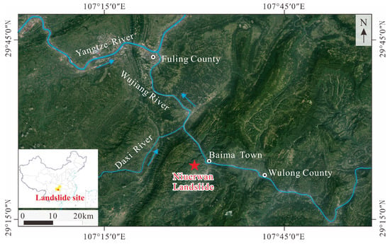
Figure 1.
Geographic location of the study area.
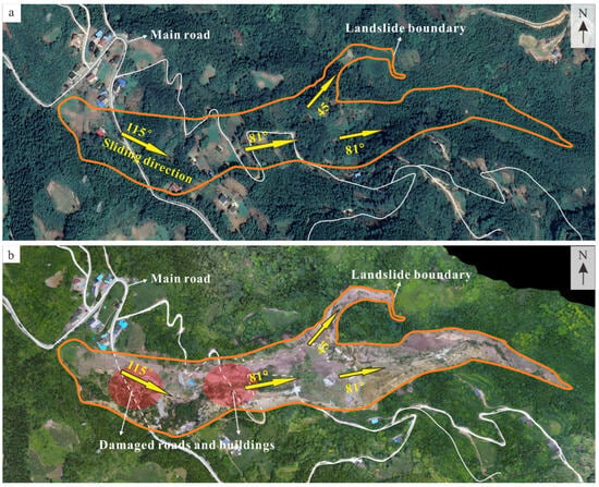
Figure 2.
Remote sensing images and on-site photos of the Niuerwan landslide. (a): Remote sensing image before the landslide (data from Google Earth Image); (b): Unmanned aerial vehicle (UAV) image after the landslide.
2.1.2. Geological Structure and Formation Lithology
The study area is located at the intersection of the southern end of the Sichuan Tai’ao Sichuan Southeast Depression Fold Belt and the Sichuan Guizhou Meridian Structural Belt on the Yangtze Paraplatform. The main control structure is the Baima Syncline, the axis of which is located west of Baima Town. The axis of the southern section of the syncline strikes southwest; the strike of the axis of the middle section changes from southwest to north and northeast; and the axis of the northern section strikes north and northeast. Because the study area is located at the intersection of complex faults and folds, strong tectonic activities have caused the rock mass in the area to become fragmented (Figure 3).
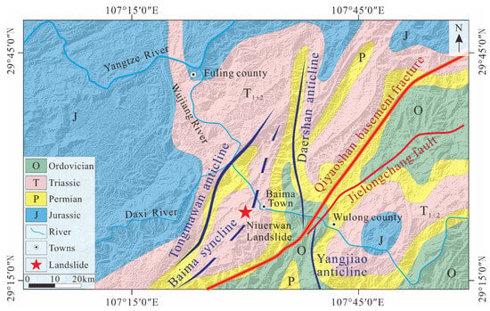
Figure 3.
Geologic map of the study area.
The lithologies in the study area are as follows: (1) Quaternary residual slope deposits (Q4el+dl) are mainly composed of gravel-bearing clay, and the parent rocks are mainly sandy mudstone, shale, and marlite, with poor roundness and a thickness of 0–9.30 m. (2) The Middle Triassic Badong Formation (T2b) is mainly composed of sandy mudstone, intercalated with calcareous shale and a thin layer of marlite. This layer is soft and has a high degree of weathering and low shear strength. It is prone to collapse or sliding, providing the materials for landslides. There are multiple sets of structural planes developed in the bedrock of the lower part of the slide mass, among which the three main structural planes are 300–338° ∠ 62–86° (F1), 30–42° ∠ 71–88° (F2), and 115–150° ∠ 10–38° (F3). In particular, F3 is the stratum occurrence and the main structural plane controlling the landslide, and F1 and F2 are a group of conjugate shear joints. The three structural planes cut the bedrock into broken rock masses (Figure 4).
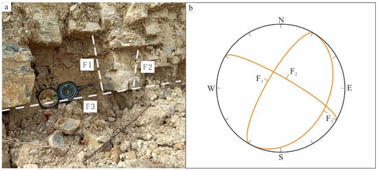
Figure 4.
(a): The exposed bedrock of right bound; (b): Stereographic projection of rock mass of the landslide.
2.1.3. Meteorology and Hydrology
The Wulong District has a typical subtropical humid monsoon climate, with abundant rainfall from May to October. The average annual rainfall is 1100 mm. The daily rainfall in the month before the landslide is shown in Figure 5. The study area is a sloped terrain that is high in the west and low in the east, which is conducive to the discharge of surficial water. There is no perennial surficial water in the landslide area, and the surficial water is mainly discharged through gullies and drainage ditches.
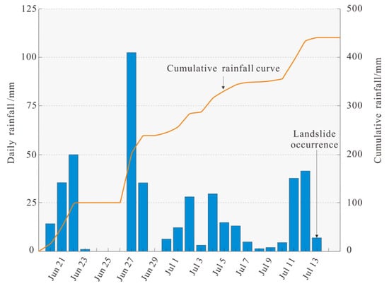
Figure 5.
Daily rainfall in the study area [].
The surficial water runs into the gullies. Due to the cracks in the rock and soil in the area, the surficial water infiltrates into the depth. Moreover, the drainage ditches in some areas discharge water into off-road rocks, causing saturation of the rock and soil. Under such drainage conditions, continuous rainfall is a key driving factor of the landslides in this area. The loose residual slope deposits and developed bedrock fissures enable rainwater infiltration, which not only increases the bulk density of the rock mass but also weakens the shear strength of the rock and soil, greatly reducing its stability.
2.2. Movement Characteristics of the Landslide
According to the remote sensing images taken before and after the landslide (Figure 2), as well as a field investigation, the process of the landslide was as follows: the sliding body became unstable under continuous heavy rainfall, and the front of the sliding body began to slip first. Then, due to the lack of support in the front, the middle and rear parts of the sliding body slide downward. After moving a certain distance, the sliding body was divided into two parts: N45°E and N81°E due to the ridge terrain. The maximum movement distance was about 1.4 km, and the leading edge was pointy. The area of the landslide was about 13.4 × 10⁴ m2, the average thickness of the accumulation body was about 11.08 m, and the volume was 147.5 × 10⁴ m3 (Figure 6, Figure 7 and Figure 8). The landslide resulted in the collapse of eight houses and damaged provincial highway S529 and a shale gas pipeline. According to the movement and accumulation characteristics of the landslide, the landslide was divided into the sliding source area, the propagation area, and the debris flow accumulation area (Figure 7).
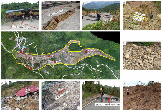
Figure 6.
Landslide characteristics. (a,b): Tension cracks in the plant and road on the northern side of the sliding source area; (c): Extruded road on the northern boundary of the sliding source area; (d): Collapsed house in the sliding source area; (e): Outcrops of geotechnical bodies on the southern boundary of the sliding source area; (f): Extruded road on the southern boundary of the sliding source area; (g): Outcrops of geotechnical bodies on the northern boundary of the sliding source area; (h): Stones in the propagation area; (i): Loose piles of material in the debris flow accumulation area.
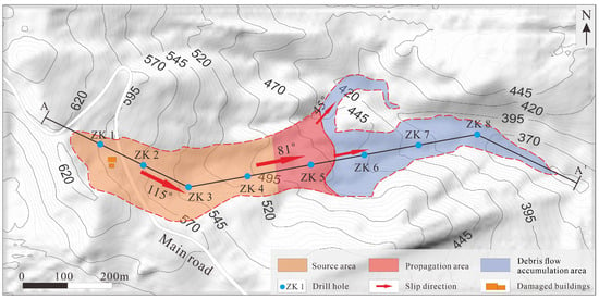
Figure 7.
Plane view of the Niuerwan landslide. The continuous black line AA’ represents the profile line laid out along the main sliding direction, and the broken red line represents the boundary line of the landslide area.
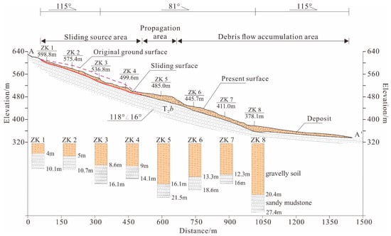
Figure 8.
Sectional view of the Niuerwan landslide. ZK1-8 shows the exploration drill holes arranged along the main profile line after the occurrence of the landslide, the upper yellow area in the drill hole histogram represents the thickness of the landslide accumulation, and the lower white area indicates the bedrock.
2.2.1. Sliding Source Area
The landform of the sliding source area was characterized by gentle (14–18°) slopes. The bedrock of the sliding body was the sandy mudstone of the Triassic Badong Formation, and the surface was covered with Quaternary residual slope deposits with a thickness of about 0–9.30 m. The sliding source area was long and band-shaped, with a width of 150–200 m and a length of 600 m. The elevation of the trailing edge was 620 m (a.s.l), and the elevation of the shear outlet was 490 m (a.s.l), i.e., a height difference of 130 m. The area of the trailing edge was 6 × 10⁴ m2. The thickness of the sliding body was 10–30 m, and the volume was 147.5 × 10⁴ m3. After cutting out from the shear outlet, the sliding body moved about 10–20 m in the N115°E direction, which was close to the occurrence of the rock formation. About 70 × 104 m3 of the sliding body was left in the sliding source area and formed accumulations. In the accumulation body, there were destroyed houses and roads (Figure 6), the composition of the accumulation body was gravel soil, and the parent rock was mainly sandy mudstone. Sliding has already occurred in this area, and the soil was loose. Under heavy rainfall, the accumulation body may further slide and form a debris flow.
2.2.2. Propagation Area
The propagation area is one of the main deposition areas of the landslide. The area of the accumulation area was 7 × 10⁴ m2. After the sliding body became unstable, about 70 × 104 m3 of the sliding body slid downward. Later, due to the influence of the terrain, the sliding direction changed to N81°E. The lower bedrock was fractured, and the loose and water-saturated residual upper layer of the slope quickly disintegrated and formed a debris flow, with a maximum distance of 1400 m.
2.2.3. Debris Flow Accumulation Area
The debris flow moved along the main sliding direction (N81°E). Affected by the raised ridge, the debris flow was divided into two parts, which moved along the valleys in the N45°E and N81°E directions. The majority of the sliding body moved along the N81°E direction. Due to the narrowing of the valley, the kinetic energy of the sliding body decreased, the flow velocity gradually decreased, and the leading edge pinched out. A small portion of the sliding body moved along the N45°E direction after crossing the raised ridges and formed an accumulation body. The entire accumulation area was approximately pincer-shaped, the elevations of the trailing edge and leading edge of the valley were 450 m (a.s.l) and 335 m (a.s.l), respectively, with a height difference of 115 m and a length of 750 m. The area was about 6 × 10⁴ m2, and the maximum accumulation thickness was about 20 m. The deposits in this area were loose mixtures of Quaternary residual slope soil and sandy mudstone, and the particle size was smaller than that of the deposits in the propagation area.
2.3. Methods
2.3.1. InSAR Monitoring
SAR interferometry (InSAR) is one of the most advanced tools for monitoring landslide deformation and can cover areas with a broad range of climatic and geomorphic conditions [,,]. Thus, a total of 83 ascending C-band Sentinel−1 SAR Interferometric Wide swath (IW) images acquired from 24 October 2017 to 7 July 2020 covering the study area were collected to investigate the deformation characteristics of the Niuerwan landslide in this study. The SAR images have a spatial resolution of 20 m in azimuth and 5 m in range. The majority of SAR images have a revisit period of 12 days, with a few having a period of 24 days. The detailed parameters for the SAR images used in this study are presented in Table 1. The flow chart of the InSAR processing is presented in Figure 9. First, to ensure an effective coherence between the primary image and secondary images, the one in the middle of the image sequence is selected as the primary image (i.e., 11 January 2019), and all the secondary images are accurately coregistered to the geometry of the primary image based on the Precise Orbit Ephemerides (POD) and external Copernicus DEM. The DEM data were downloaded from European Space Agency (https://panda.copernicus.eu/panda, accessed on 20 August 2023), with a spatial resolution of 30 m. Second, to reduce the influences of temporal and spatial decorrelation, the strategy of small baseline subset (SBAS) [] is adopted to generate all possible interferograms based on the resampled single-look complex (SLC) images. The temporal and spatial baselines were set at 60 d and 250 m, respectively. The interferograms were multi-looked using a factor of 4 in range and 1 in azimuth. The topographic phase component is estimated and removed using one arc-second DEM with a spatial resolution of 30 m. After the removal of topographic phase, the differential interferograms are filtered using an adaptive filtering function based on the local fringe spectrum [], and unwrapped using the minimum cost flow algorithm []. A small window size (i.e., 32 × 32) was used to filter the interferograms to avoid the loss of information at the edge of fringes. Then, the errors related to phase unwrapping, atmospheric delay and residual topography are carefully checked and corrected, and the high-quality unwrapped interferograms are finally selected from the corrected results to estimate the displacement rate and time series in the line-of-sight (LOS) direction. The spatio-temporal baseline distribution of the finally selected high-quality interferograms is presented in Figure 10. The method of the weighted averaging of interferograms (i.e., stacking) is used to estimate the average annual displacement rate, which can suppress the influence of the residual atmospheric artifacts to some extent []. The displacement time series is inverted using a singular value decomposition algorithm []. The phase unwrapping errors are corrected by manual method base on the principle of phase compensation, i.e., subtracting or adding an integer number of phase cycle (s) at the phase jump pixels []. The tropospheric delays are estimated and corrected using an empirical linear relationship between the InSAR phase delay and the elevation [].

Table 1.
The detailed parameters for the SAR images used in this study.
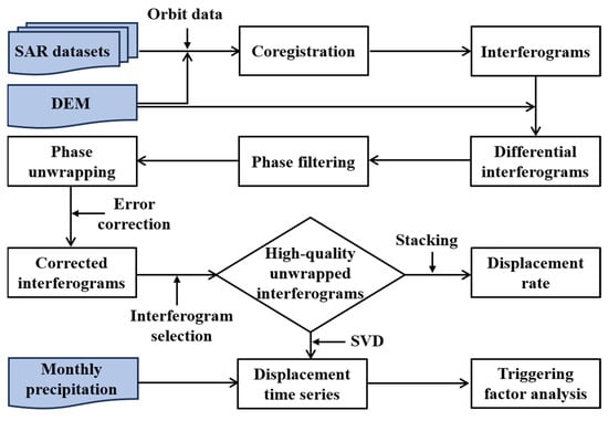
Figure 9.
Flow chart of the InSAR processing and analysis of triggering factor of the Niuerwan landslide.
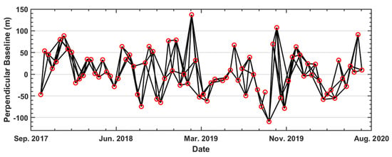
Figure 10.
Acquisition dates and interferometric combinations of the Sentinel−1 SAR images used in this study. The red circles denote the Sentinel−1 acquisitions, and the black lines indicate the combination of the interferometric pairs.
To determine the possible triggering factor of the Niuerwan landslide, the monthly rainfall data between 1 August 2017 and 1 September 2020 are collected from NASA’s Global Rainfall Measurement Mission (GPM). As is shown in Figure 9, the correlation analysis between the monthly rainfall and displacement time series in the representative deformation area is conducted.
2.3.2. Numerical Analysis
The numerical simulation of the landslide was performed using the PFC3D 2017 software to study the movement and accumulation processes of the sliding body after instability. The ball–wall model in PFC3D was used to conduct the modeling [], the sliding surface was set as a rigid wall, and ball particles were used to simulate the sliding body. First, according to a 1:1000 topographic map of the Niuerwan landslide obtained from the UAV at the site, the rigid wall boundaries of the calculation model were determined. Then, the generating tool was used to generate ball particles to simulate the rock and soil mass of the landslide. The sliding body was modeled as a dual structure with upper and lower layers. The total thickness of the sliding body was 20 m, and the thicknesses of the upper and lower layers were 10 m. The linear contact model was used for the upper layer of particles in order to simulate loose and saturated soil, and a parallel bond model was used to simulate the lower layer of particles (Figure 11).
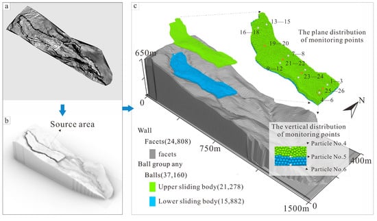
Figure 11.
PFC3D model of the Niuerwan landslide. (a): Contour data; (b): Three-dimensional terrain generated using Rhino; (c): PFC numerical model.
In this study, a virtual triaxial test was carried out for the purpose of parameter calibration. Figure 12 shows the stress–strain curve. In order to be consistent with the particle size in the model, the sample in the triaxial test was a cylinder with a diameter of 50 m and a height of 100 m. The number of particles was about 12,000, with a minimum radius Rmin of 1.2 m and a maximum radius Rmax of 2 m. As can be seen from Figure 12, for the upper layer, the peak strength under three different confining pressures was basically the same since there was no bond parameter. For the lower bedrock, the compressive strength of the sample was low under the low confining pressure. As the confining pressure increased, the compressive strength of the sample also increased, which was consistent with the actual situation. The simulation results were compared with the actual movement and accumulation characteristics. After optimization and adjustment of the microscopic parameters, the simulated landslide motion was basically consistent with the actual landslide characteristics. Thus, the microscopic parameters for simulating the Niuerwan landslide were determined (Table 2).
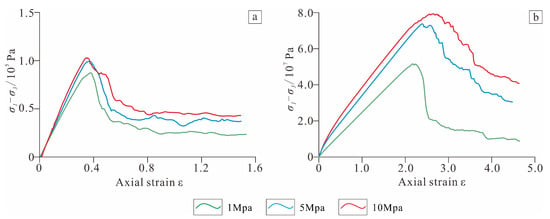
Figure 12.
Triaxial compression test conducted in PFC3D. (a): Residual soil under different pressure conditions; (b): Mudstone under different pressure conditions.

Table 2.
Microscopic parameters of the PFC3D model.
3. Results
3.1. Deformation Characteristics Revealed by InSAR Observations
In general, the deformation signal often occurs prior to landslide rupture. We selected the Sentinel−1 SAR images acquired between 24 October 2017 and 7 July 2020 before the failure to reveal the deformation characteristics of the Niuerwan landslide. The small baseline subset (SBAS) InSAR [] method was used to process the SAR images based on the commercial GAMMA 2015 software, thus generating the average annual displacement rate and cumulative displacement of the landslide. Figure 13a,b show the average annual displacement rate and cumulative displacement in the line-of-sight (LOS) direction of the Niuerwan landslide, respectively. It is worth specifying that the study area is covered by dense vegetation, thus causing the low coherence of the InSAR interferograms. As a consequence, the displacement maps presented in Figure 13a,b are inevitably affected by decorrelation noises. However, the pre-event deformation of the Niuerwan landslide can be clearly observed from the InSAR-derived annual displacement rate and cumulative displacement. InSAR results show that the maximum displacement rate is more than 40 mm/yr, and the largest cumulative displacement exceeds 100 mm during the period of 24 October 2017 and 7 July 2020. The deformation of the sliding source area and part of the debris flow accumulation area and its periphery is more obvious.
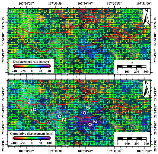
Figure 13.
The average annual displacement rate (a) and cumulative displacement (b) of the Niuerwan landslide along the line-of-sight (LOS) direction retrieved from Sentinel−1 images between 24 October 2017 and 7 July 2020.
Four points P1–P4 located on the obvious deformation areas of the landslide were selected to investigate the temporal evolution characteristics of the Niuerwan landslide, where points P1 and P2 are located in the sliding source area, point P3 is located in the propagation area, and point P4 is located in the southern boundary area of the propagation area. Moreover, the monthly rainfall data were collected from NASA’s GPM, and freely downloaded from https://disc.gsfc.nasa.gov/datasets?keywords=GPM&page=1 (accessed on 18 August 2023), consistent with the temporal coverage of the Sentinel−1 images, to examine the relationship between deformation and rainfall. Figure 14 shows the correlation analysis between the displacement time series of points P1–P4 and monthly rainfall. As shown in Figure 14, the rainfall in the study area is mainly concentrated in summer (i.e., from May to July) each year, the cumulative rainfall in the summer of 2020 is much greater than that in the summers of 2019 and 2018. In particular, the peak rainfall was observed in June of 2020, which reached 428 mm. We can clearly see that the nonlinear periodic deformation characteristic of the Niuerwan landslide was measured during the InSAR monitoring period, and the landslide deformation showed a strong relationship with monthly rainfall. The landslide displacement was accelerated for the first time in August 2018, accompanied by the continuous heavy rainfall event in the study area. Then, the landslide deformation slowed down with the continuous reduction of rainfall during the period from October 2018 to March 2019. However, the landslide displacement was significantly accelerated again in April 2019 with the beginning of continuous heavy rainfall in the summer of 2019. The heavy rainfall in the study area from May to July 2020 occurred more frequently and lasted longer than usual, which caused the accumulative rainfall to reach the highest in history. Based on the displacement change data at points P1 and P2, the last InSAR observations prior to the landslide (i.e., 4 July 2020) indicate that the landslide has a remarkable accelerated deformation associated with the peak rainfall in June 2020. The landslide was directly triggered by the strong rainfall in June 2020. It is worth noting that long-term cumulative rainfall has also led to significant deformation of localized residual slope deposits in the propagation area as well as in its boundary regions. These regions may still have a large risk of landslide in the future in the case of the occurrence of continuous heavy rainfall.
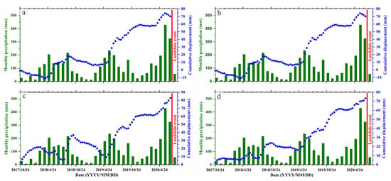
Figure 14.
LOS displacement time series of points P1–P4 with monthly rainfall, the location of P1-P4 is marked in Figure 13b with white circles. (a): P1; (b): P2; (c): P3; (d): P4.
3.2. Movement Characteristics Revealed by PFC3D Observations
3.2.1. Landslide Movement and Accumulation
Figure 15 shows the movement of the Niuerwan landslide. It can be seen that the total duration of the landslide was about 360 s, and that the landslide accumulation corresponds with the evidence from the field survey seems evident. Owing to the convenience of numerical simulation, separating the sliding body into two layers facilitated the analysis of the characteristics of both the upper and lower sliding bodies.
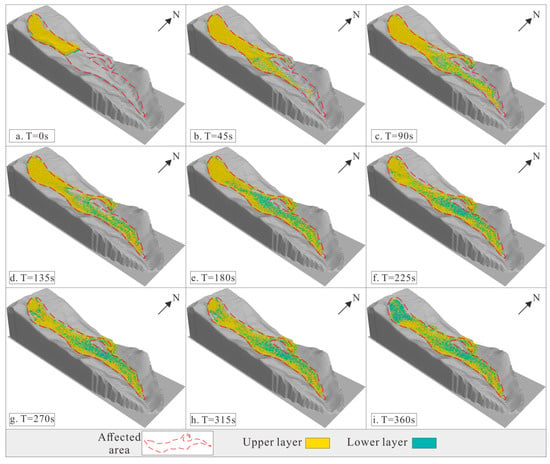
Figure 15.
Movement characteristics of different parts of the sliding body of the Niuerwan landslide.
The upper sliding body was composed of loose residual slope deposits, and it was close to saturation due to the preceding rainfall event. When the landslide became unstable, the upper sliding body disintegrated rapidly to form a debris flow (Figure 15a–d). Most of the upper layer reached the leading edge of the landslide, and the movement distance reached 1 km. The lower layer was mainly composed of sandy mudstone with strong weathering and well-developed joints. It also disintegrated and was mixed with the upper sliding body as it moved downwards (Figure 15e,f). However, the lower sliding body still maintained a good structure (Figure 15g–i). The movement distance was relatively short, and a large amount of the sliding body remained in the sliding source area.
The movement of the landslide in different stages was as follows.
0–45 s: After the sliding body became unstable, the sliding body in the front of the sliding source area was cut out from the shear outlet position and began to slide in the N81°E direction, and the maximum velocity was greater than 15 m/s (Figure 16a,b). The upper layer moved in a fluidized state, and the lower layer gradually disintegrated. The two layers mixed while moving downward to form a debris flow (Figure 15b). Due to the obstruction of its movement path by the ridge, the sliding body was diverted. Most of the sliding body continued to move in the N81°E direction, and a small part of the sliding body moved in the N45°E direction.
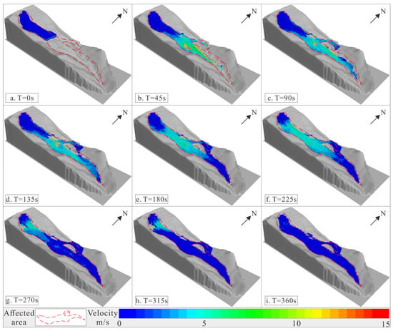
Figure 16.
Velocity distribution of the Niuerwan landslide.
45–135 s: The sliding body continued to move, and the diversion phenomenon became more obvious. Moreover, the sliding body in the middle and rear sections of the sliding source area lost the support of the front sliding body, and a larger-scale slide occurred. However, due to the gradient of the slope, the sliding velocity was relatively low, mostly 4–6 m/s (Figure 16c,d).
135–225 s: The movement of the sliding body became more obvious. The middle of the sliding body continued to move at a velocity of 4–10 m/s, while the front part of the sliding body began to come to a stop due to the gradual narrowing of the valley (Figure 16e,f). Additionally, the fluidization characteristics became more obvious, and the upper layer engulfed the lower layer and reached the accumulation area (Figure 15e,f).
225–360 s: The front part of the sliding body had stopped moving and formed accumulation bodies, and the rear part of the sliding body also gradually stopped moving due to the resistance provided by the front accumulations (Figure 16g–i). The final accumulation characteristics of the landslide were consistent with the actual situation.
3.2.2. Velocity and Displacement Trajectory
As shown in Figure 11, in order to monitor the velocity and trajectory of the landslide, a total of 28 monitoring particles were placed in the front, middle, and rear parts of the upper and lower sliding body. The trajectories of particles 19–28 (Figure 17) and the velocities of particles 1–6 in the front, particles 7–12 in the middle, and particles 13–18 in the rear part of the sliding body (Figure 18) were obtained.
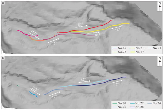
Figure 17.
Trajectories of the monitoring particles. (a): movement trail of the upper layer monitoring particles; (b): movement trail of the lower layer monitoring particles.
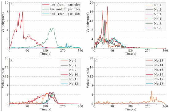
Figure 18.
Velocity curves of the monitoring particles. (a): average velocity curve; (b): velocity of front particles; (c): velocity of middle particles; (d): velocity of rear particles.
In the front part of the sliding body, both the upper and lower layers disintegrated and formed a debris flow. The distances of the leading-edge particles (1–6 and 27–28) were within a very narrow range (435–472 m; Figure 17), as was the velocity variation (maximum: 18 m/s; Figure 18b). The velocities of particles 7–12 in the middle part were very similar, with a maximum velocity of about 5 m/s (Figure 18c). The distance of the upper layer particle (21) was about 403 m, while that of the lower layer particle (22) was only 155 m. For the rear particles, only particle 13 had a maximum velocity of about 5 m/s, and particles 14–18 barely moved (Figure 18d). Moreover, the upper layer particle (19) moved about 200 m, while the lower layer particle (20) only moved 72 m.
From the above analysis, it can be seen that there were large differences in the movement characteristics of the upper and lower layers of the sliding body. In the front of the sliding body, both the upper and lower layers of the sliding body disintegrated and formed a debris flow, exhibiting similar movement characteristics. In the middle and rear parts of the sliding body, the upper layer disintegrated more thoroughly, exhibiting obvious fluidization characteristics, and the movement distance reached twice that of the lower sliding body. The lower sliding body maintained a relatively complete structure and moved as a whole (Figure 17). The movement directions of the different parts of the sliding body revealed its instability mode. The rear part of the sliding body moved along the N112°E–N122°E direction, which was consistent with the inclination of the formation (N115°E). Therefore, the rear part slid along the true dip direction. Affected by the mountain on the right side of the landslide, the front and middle parts of the sliding body were deflected to N70°E–N82°E, which was along the apparent dip direction (Figure 17).
4. Discussion
4.1. Identification of Slippery Features
Interferometric synthetic aperture radar (InSAR) proves to be effective for landslide investigation. However, the InSAR technique is mainly aimed at monitoring the surface deformation of landslides [,], while this paper identifies several deformation areas before the landslides by InSAR, including the source area, the propagation area, and in the southern boundary area of the propagation area (Figure 13), in which the rock body in the source area slid along the level (115°) in the direction of the layer. Then, due to the influence of the topographic obstruction, the sliding material hit the southern rock wall and broke, and the circulation direction changed from S115°E to N81°E and slid along the direction of the apparent tendency. Although the deformation value is larger in the southern boundary area of the propagation area, the stratigraphic structure on the airside of this area is a counter-trending slope, which is more resistant to sliding force. Under this round of rainfall, the antislip force of the slope is still larger than the sliding force, so large-scale sliding did not occur for the time being. It shows that it is necessary to combine the stratigraphic structure and topographic conditions with the InSAR monitoring results to comprehensively determine the slip-prone area and sliding direction of the slope, so as to increase the accuracy of the identification of landslide instability and motion characteristics.
4.2. Hazard Model
In the sandstone and mudstone mountainous areas in southwestern China, there are a number of bedding landslides with a relatively gentle formation dip, such as the Niuerwan landslide, the Wushanping landslide, and the Xianchi Reservoir landslide [,]. These types of landslides are characterized by slow movement and long-runout movement. Hence, the disaster mode should be further explored. The PFC3D 2017 software was used to simulate the Niuerwan landslide. The results showed that the landslide lasted 360 s, with a maximum velocity of 18 m/s, a maximum average velocity of 8 m/s, and a maximum movement distance of 1250 m. Based on the movement and accumulation characteristics of the landslide, it is believed that the long-runout movement process of these types of landslides will go through three stages.
(1) Global instability stage: The stratum was characterized by global instability, and the range of the sliding source area was large. The potential energy was converted to kinetic energy, and there were large differences in the velocities of the different parts of the sliding body. The kinetic energy of the front part of the sliding body was large, whereas those of the middle and rear parts were relatively small.
(2) Acceleration stage: the sliding body began to disintegrate to form a debris flow. Due to the differences in the upper and lower layers of the sliding body, they had different movement characteristics. Due to the frictional resistance of the base and the overlying soil, as well as the flat terrain, the lower layer of the sliding body did not experience strong collisions, maintaining a relatively complete structure. The upper layer of the sliding body was composed of saturated residual slope soil, which was completely fragmented and exhibited obvious fluidization characteristics. Moreover, the upper layer of the sliding body engulfed the fragments in the top of the lower layer, formed a debris flow, and began to accelerate.
(3) Fluidization and accumulation stage: With further movement of the sliding body, the mixed debris flow moved a long distance and accumulated in the accumulation area below.
5. Conclusions
In this study, detailed field survey, InSAR monitoring and numerical simulation were used to carry out systematic analysis of the bedding landslides with a dual soil–rock structure under rainfall conditions. The following conclusions were obtained.
(1) Heavy rainfall and the dual soil–rock structure led to the enrichment of groundwater in the weak interlayer of the sliding body. The saturation of the residual slope soil layer on the surface not only reduced the shear strength of the rock mass but also increased the sliding force, which jointly caused deep instability of the rock mass and fluidization and long-distance movement of the surface.
(2) The InSAR method usually only monitors the surface displacement of the landslide, but lacks the detection of the deep geological structure of the landslide. While interpreting the surface deformation, it is necessary to combine with the stratigraphic structure to determine the slip-prone area and the direction of sliding. On this basis, numerical methods can also be combined to determine the scope of disaster. The above comprehensive analysis method can provide quantitative support for other similar landslides in terms of destabilization area and disaster pattern identification as well as disaster avoidance and protection.
(3) There were large differences in the movement characteristics of the upper and lower layers of the sliding body. In the front part of the sliding body, disintegration and fragmentation of both the upper and lower layers occurred, and their movement characteristics were very similar. In the middle and rear parts of the sliding body, the upper layer disintegrated more thoroughly, exhibiting fluidization characteristics, and the movement distance reached twice that of the lower layer. The lower layer of the sliding body still maintained a relatively complete structure and moved as a whole. The movement directions of the front, middle, and rear parts of the sliding body also indicated its special instability mode. The rear part of the sliding body moved along the true dip direction, while the front and middle parts of the sliding body were affected by the terrain and moved along the apparent dip.
(4) The long-distance movement of these types of landslides mainly occurred in the upper sliding body, and the fluidization of the upper sliding body greatly increased the disaster range of the landslide. The long-distance movement of the landslide can be divided into three stages: global instability, acceleration, and fluidization and accumulation stages. The results of this study provide references for further study of the long-runout movement characteristics of this type of landslide.
In addition, in the risk evaluation of long-runout fluidization landslides in sandy-shale strata, the investigation should be fully based on the characteristics of the long-runout fluidization movement, thereby providing quantitative references for disaster prevention and mitigation.
Author Contributions
All authors contributed extensively to the present paper. Conceptualization and writing, Y.G.; methodology and writing, J.L.; InSAR monitoring data analysis, X.L.; software, W.W.; investigation, H.Z. and P.L. All authors have read and agreed to the published version of the manuscript.
Funding
This research was funded by Institute of Geo-Mechanics (DZLXJK201901), National Natural Science Foundation of China (42177172 and 41907257), the National Key Research and Development Program of China “The Disaster Pattern and Risk Prevention Technology of Large Landslides in the Karst Mountain Area” (Nos. 2018YFC1504804 and 2018YFC1504806).
Data Availability Statement
The datasets generated during and/or analyzed during the current study are available from the corresponding author on reasonable request.
Acknowledgments
We acknowledge support from Institute of Geo-Mechanics (DZLXJK201901), National Natural Science Foundation of China (42177172 and 41907257), the National Key Research and Development Program of China “The Disaster Pattern and Risk Prevention Technology of Large Landslides in the Karst Mountain Area” (Nos. 2018YFC1504804 and 2018YFC1504806).
Conflicts of Interest
The authors declare no conflict of interest.
References
- Gao, Y.; Li, B.; Feng, Z.; Zuo, X. Global climate change and geological disaster response analysis. J. Geomech. 2017, 23, 65–77. [Google Scholar]
- Heim, A. Bergsturz und Menschenleben; Fretz & Wasmuth: Tübingen, Germany, 1932. [Google Scholar]
- Voight, B.; Pariseau, W.G. Rockslides and avalanches: An introduction. Developments in Geotechnical Engineering; Elsevier: Amsterdam, The Netherlands, 1978; p. 10. [Google Scholar]
- Xu, Q.; Hunag, R.Q.; Yin, Y.P.; Hou, S.S.; Dong, X.J.; Dong, X.J.; Fan, X.M.; Tang, M.G. The Jiweishan landslide of 5 June 2009 in Wulong, Chongqing: Characteristics and failure mechanism. J. Eng. Geol. 2009, 17, 433–444. (In Chinese) [Google Scholar]
- Yin, Y.P. Mechanism of apparent dip slide of inclined bedding rockslide: A case study of Jiweishan rockslide in Wulong, Chongqing. Chin. J. Rock Mech. Eng. 2010, 29, 217–226. (In Chinese) [Google Scholar]
- Yin, Y.P.; Wang, W.P.; Zhang, N.; Yan, J.K.; Wei, Y.J.; Yang, L.W. Long runout geological disaster initiated by the ridge-top rockslide in a strong earthquake area: A case study of the Xinmo landslide in Maoxian County, Sichuan Province. Geol. China 2017, 44, 827–841. (In Chinese) [Google Scholar]
- Li, B.; Gao, Y.; Yin, Y.; Wan, J.; He, K.; Wu, W.; Zhang, H. Rainstorm-induced large-scale landslides in northeastern Chongqing, China, 31 August to 2 September 2014. Bull. Eng. Geol. Environ. 2022, 81, 271. [Google Scholar] [CrossRef]
- Dahal, R.K.; Hasegawa, S. Representative rainfall thresholds for landslides in the Nepal Himalaya. Geomorphology 2008, 100, 429–443. [Google Scholar] [CrossRef]
- Bhardwaj, A.; Wasson, R.J.; Ziegler, A.D.; Chow, W.T.L.; Sundriyal, Y.P. Characteristics of rain-induced landslides in the Indian Himalaya: A case study of the Mandakini catchment during the 2013 flood. Geomorphology 2019, 330, 100–115. [Google Scholar] [CrossRef]
- Iverson, R.M. Landslide triggering by rain infiltration. Water Resour. Res. 2000, 36, 1897–1910. [Google Scholar] [CrossRef]
- Matsuura, S.; Asano, S.; Okamoto, T. Relationship between rain and meltwater, pore-water pressure and displacement of a reactivated landslide. Eng. Geol. 2008, 101, 49–59. [Google Scholar] [CrossRef]
- Xu, Q.; Zhang, L. The mechanism of a railway landslide caused by rainfall. Landslides 2010, 7, 149–156. [Google Scholar] [CrossRef]
- Vassallo, R.; Grimaldi, G.M.; Di Maio, C. Pore water pressures induced by historical rain series in a clayey landslide: 3D modeling. Landslides 2015, 12, 731–744. [Google Scholar] [CrossRef]
- Xu, Q. The 13 August 2010 catastrophic debris flows in Sichuan province: Characteristics, genetic mechanism and suggestions. J. Eng. Geol. 2010, 18, 596–608. (In Chinese) [Google Scholar]
- Gao, Y.; He, K.; Li, Z.; Gao, H.Y.; Wei, T.Y.; Xing, A.G.; Li, B. An analysis of disaster types and dynamics of landslides in the southwest karst mountain areas. Hydrogeol. Eng. Geol. 2020, 47, 14–23. (In Chinese) [Google Scholar]
- Gao, H.Y.; Gao, Y.; He, K.; Li, B.; Zhao, Z.N.; Chen, L.C.; Wang, Y.F. Impact and scraping effects of the high-elevation, long-runout “7.23” landslide in Shuicheng, Guizhou. Carsol. Sin. 2020, 39, 535–546. (In Chinese) [Google Scholar]
- Li, Z.; Gao, Y.; He, K.; Gao, H.Y.; Wei, T.Y.; Liu, Z.; Zhao, Z.N. Analysis of the fluidization process of the high position and long-runout landslide in Shuicheng, Liupanshui, Guizhou Province. J. Geomech. 2020, 26, 520–532. (In Chinese) [Google Scholar]
- Buss, E.; Heim, A. Der Bergsturz von Elm den 11 September 1881: Denkschrift. Z. Der Dtsch. Ges. Für Geowiss. 1881, 540–564. [Google Scholar]
- Kent, P.E. The transport mechanism in catastrophic rock falls. J. Geol. 1966, 74, 79–83. [Google Scholar] [CrossRef]
- Sassa, K. Geotechnical model for the motion of landslides (Special lecture). In Proceedings of the 5th International Symposium on Landslides, Lausanne, Switzerland, 10–15 July 1988; A.A. Balkema: Amsterdam, The Netherlands, 1989; Volume 1, pp. 37–56. [Google Scholar]
- Hungr, O. A model for the runout analysis of rapid flow slides, debris flows, and avalanches. Can. Geotech. J. 1995, 32, 610–623. [Google Scholar] [CrossRef]
- Davies, T.R.; McSaveney, M.J.; Hodgson, K.A. A fragmentation-spreading model for long-runout rock avalanches. Can. Geotech. J. 1999, 36, 1096–1110. [Google Scholar] [CrossRef]
- Xing, A.G.; Gao, G.Y.; Chen, L.Z.; Hu, H.T. Study on hydrodynamics mechanism of large highspeed landslide in the set-out stage. Chin. J. Rock Mech. Eng. 2004, 23, 607–613. (In Chinese) [Google Scholar]
- Xing, A.G.; Yin, Y.P. Whole course analysis on hydrokinetics mechanism of Touzhai gully landslide. J. Tongji Univ. Nat. Sci. 2009, 37, 481–485. (In Chinese) [Google Scholar]
- De Blasio, F.V.; Crosta, G.B. Fragmentation and boosting of rock falls and rock avalanches. Geophys. Res. Lett. 2015, 42, 8463–8470. [Google Scholar] [CrossRef]
- Lai, Z.; Vallejo, L.E.; Zhou, W.; Ma, G.; Espitia, J.M.; Caicedo, B.; Chang, X. Collapse of granular columns with fractal particle size distribution: Implications for understanding the role of small particles in granular flows. Geophys. Res. Lett. 2017, 44, 12–181. [Google Scholar] [CrossRef]
- Gao, Y.; Yin, Y.; Li, B.; Wei, T.; Li, Z.; Gao, H. The role of fluid drag force in the dynamic process of two-phase flow-like landslides. Landslides 2022, 19, 1791–1805. [Google Scholar] [CrossRef]
- Evans, S.G.; Hungr, O.; Clague, J.J. Dynamics of the 1984 rock avalanche and associated distal debris flow on Mount Cayley, British Columbia, Canada; Implications for Landslide Hazard Assessment on Dissected Volcanoes. Eng. Geol. 2001, 61, 29–51. [Google Scholar] [CrossRef]
- Sassa, K.; Wang, G.; Fukuoka, H.; Wang, F.; Ochiai, T.; Sugiyama, M.; Sekiguchi, T. Landslide risk evaluation and hazard zoning for rapid and long-travel landslides in urban development areas. Landslides 2004, 1, 221–235. [Google Scholar] [CrossRef]
- Sassa, K.; Nagai, O.; Solidum, R.; Yamazaki, Y.; Ohta, H. An integrated model simulating the initiation and motion of earthquake and rain induced rapid landslides and its application to the 2006 leyte landslide. Landslides 2010, 7, 219–236. [Google Scholar] [CrossRef]
- Zhang, Y.J.; Xing, A.G.; Zhu, J.L. Dynamics analysis of Niujuangou rockslide-debris avalanche triggered by the Wenchuan earthquake. J. Shanghai Jiaotong Univ. 2012, 46, 1665–1670. (In Chinese) [Google Scholar]
- Gao, Y.; Yin, Y.; Li, B.; Feng, Z.; Wang, W.; Zhang, N.; Xing, A. Characteristics and numerical runout modeling of the heavy rainfall-induced catastrophic landslide-debris flow at Sanxicun, Dujiangyan, China, following the Wenchuan Ms 8.0 Earthquake. Landslides 2017, 14, 1361–1374. [Google Scholar] [CrossRef]
- Gao, Y.; Yin, Y.; Li, B.; He, K.; Wang, X. Post-failure behavior analysis of the Shenzhen “12.20” CDW landfill landslide. Waste Manag. 2019, 83, 171–183. [Google Scholar] [CrossRef]
- Gao, Y.; Li, B.; Gao, H.; Chen, L.; Wang, Y. Dynamic characteristics of high-elevation and long-runout landslides in the Emeishan basalt area: A case study of the Shuicheng “7.23” landslide in Guizhou, China. Landslides 2020, 17, 1663–1677. [Google Scholar] [CrossRef]
- Zhang, Y.L.; Chen, L.; Yan, J.K.; Gao, Y. Study on the catastrophic process of rapid and long run-out landslides based on DAN-W. Northwest. Geol. 2021, 54, 204–211. (In Chinese) [Google Scholar]
- Zhang, L.; Tang, H.M.; Xiong, C.R.; Huang, L.; Zou, Z.X. Movement process simulation of high-speed long-distance Jiweishan landslide with PFC3D. Chin. J. Rock Mech. Eng. 2012, 31, 2601–2611. (In Chinese) [Google Scholar]
- Meng, H.Y.; Zhan, J.W.; Lu, Q.Z.; Zhao, C.Y.; Hang, J.L.; Sun, Y.M. Kinematics characteristics and numerical simulation analysis of “8.12” giant landslide in Shanyang county, Shaanxi province. J. Eng. Geol. 2022, 1–18. (In Chinese) [Google Scholar]
- Zhou, C.; Huang, W.; Ai, D.; Xu, H.; Yuan, J.; Kou, L.; Luo, X. Catastrophic landslide triggered by extreme rainfall in Chongqing, China: 13 July 2020, Niuerwan landslide. Landslides 2022, 19, 2397–2407. [Google Scholar] [CrossRef]
- Zhou, C.; Cao, Y.; Hu, X.; Yin, K.; Wang, Y.; Catani, F. Enhanced dynamic landslide hazard mapping using MT-InSAR method in the Three Gorges Reservoir Area. Landslides 2022, 19, 1585–1597. [Google Scholar] [CrossRef]
- Zhang, X.; Chen, L.; Zhou, C. Deformation Monitoring and Trend Analysis of Reservoir Bank Landslides by Combining Time-Series InSAR and Hurst Index. Remote Sens. 2023, 15, 619. [Google Scholar] [CrossRef]
- Su, C.; Mergili, M.; Rana, N.M.; Zhang, S.; Dai, C.; Wang, B.; Han, Y. Failure analysis and flow dynamic modeling using a new slow-flow functionality: The 2022 Jiaokou (China) tailings dam breach. Landslides 2023, 1–13. [Google Scholar] [CrossRef]
- Berardino, P.; Fornaro, G.; Lanari, R.; Sansosti, E. A new algorithm for surface deformation monitoring based on small baseline differential SAR interferograms. IEEE Trans. Geosci. Remote Sens. 2002, 40, 2375–2383. [Google Scholar] [CrossRef]
- Goldstein, R.M.; Werner, C.L. Radar interferogram filtering for geophysical applications. Geophys. Res. Lett. 1998, 25, 4035–4038. [Google Scholar] [CrossRef]
- Costantini, M. A novel phase unwrapping method based on network programming. IEEE Trans. Geosci. Remote Sens. 1998, 36, 813–821. [Google Scholar] [CrossRef]
- Lyons, S.; Sandwell, D. Fault creep along the southern San Andreas from interferometric synthetic aperture radar, permanent scatterers, and stacking. J. Geophys. Res. Solid Earth 2003, 108, B1. [Google Scholar] [CrossRef]
- Liu, X.; Zhao, C.; Zhang, Q.; Lu, Z.; Li, Z.; Yang, C.; Zhu, W.; Liu-Zeng, J.; Chen, L.; Liu, C. Integration of Sentinel−1 and ALOS/PALSAR-2 SAR datasets for mapping active landslides along the Jinsha river corridor, China. Eng. Geol. 2021, 284, 106033. [Google Scholar] [CrossRef]
- Doin, M.-P.; Lasserre, C.; Peltzer, G.; Cavalié, O.; Doubre, C. Corrections of stratified tropospheric delays in SAR interferometry: Validation with global atmospheric models. J. Appl. Geophys. 2009, 69, 35–50. [Google Scholar] [CrossRef]
- Guo, J.; Cui, Y.; Xu, W.; Yin, Y.; Li, Y.; Jin, W. Numerical investigation of the landslide-debris flow transformation process considering topographic and entrainment effects: A case study. Landslides 2022, 19, 773–788. [Google Scholar] [CrossRef]
- Jiang, Z.; Zhao, C.; Yan, M.; Wang, B.; Liu, X. The early identification and spatio-temporal characteristics of loess landslides with Sentinel−1a datasets: A case of Dingbian county, China. Remote Sens. 2022, 14, 6009. [Google Scholar] [CrossRef]
- Liang, J.; Dong, J.; Zhang, S.; Zhao, C.; Liu, B.; Yang, L.; Yan, S.; Ma, X. Discussion on InSAR identification effectivity of potential landslides and factors that influence the effectivity. Remote Sens. 2022, 14, 1952. [Google Scholar] [CrossRef]
- Zhang, H.; Gao, Y.; Li, B.; Li, J.; Wu, W. Numerical simulation analysis of the solid–liquid coupling process in a hybrid landslide: A case study of the Wushanping landslide. J. Geomech. 2022, 28, 1104–1114. (In Chinese) [Google Scholar]
- Wei, T. Study on Drag Effect of Flow Like Landslides. Master’s Thesis, Chang’an University, Xi’An, China, 2022. (In Chinese). [Google Scholar]
Disclaimer/Publisher’s Note: The statements, opinions and data contained in all publications are solely those of the individual author(s) and contributor(s) and not of MDPI and/or the editor(s). MDPI and/or the editor(s) disclaim responsibility for any injury to people or property resulting from any ideas, methods, instructions or products referred to in the content. |
© 2023 by the authors. Licensee MDPI, Basel, Switzerland. This article is an open access article distributed under the terms and conditions of the Creative Commons Attribution (CC BY) license (https://creativecommons.org/licenses/by/4.0/).