Abstract
Ground-based radar interferometry is capable of measuring target displacement to sub-mm accuracy. W-band ground-based radar has recently been investigated as a potential application for structural health monitoring. On the other hand, the application of W-band ground-based radar for natural slope monitoring is considered in this study due to its advantages in portability and recent cost-effective solutions. In radar interferometry, atmospheric phase screen (APS) is the most relevant phase disturbance that should be corrected for accurate displacement measurement. However, the APS effects in W-band radar interferometry have rarely been discussed. In this context, we study and evaluate the impacts of APS and its potential correction methods for 79 GHz ground-based radar interferometry using multiple-input and multiple-output (MIMO) radar. This paper presents an experimental investigation of a 79 GHz radar system using two types of field experiments conducted in an open flat field and a quarry site. In addition to the W-band radar system, a Ku-band (17 GHz) ground-based synthetic aperture radar (GB-SAR) system was jointly tested to compare different operating frequency bands. The result confirmed the accurate displacement estimation capability of the 79 GHz radar with an appropriate APS correction.
1. Introduction
Radar remote sensing, provided by satellite synthetic aperture radar (SAR), is capable of quantifying changes in the Earth’s surface. In particular, a series of complex SAR images can provide information on surface deformation using the interferometric SAR (InSAR) technique [1]. Due to the great advantage of the InSAR technique in terms of precision and spatial coverage, it has been applied to monitor subsidence and uplift processes in urban scenarios [2], landslide deformation, volcanic dome deformation, mining areas, and post-earthquake crustal deformation. Over the last few decades, many improvements have been made to reduce the limitations of the InSAR technique, such as temporal decorrelation, atmospheric artifacts, and phase wrapping. Despite these improvements, the satellite platform should afford the limitation of temporal resolution.
On the other hand, recent advancements in ground-based SAR (GB-SAR) allow near real-time deformation monitoring [3]. In addition to the shorter temporal resolution capability, GB-SAR can achieve zero spatial baseline observation and maximize displacement sensitivity by selecting the appropriate radar location due to its flexibility in observation geometry. The GB-SAR system, consisting of a radar sensor and a mechanical linear rail (guide), is the most popular system configuration [4], while some use an arc-scanning configuration [5].
All these radar types require mechanical movement of the antennas for synthetic aperture processing. Multiple-input and multiple-output (MIMO) radar technology, on the other hand, does not require mechanical movement of the antennas and is realized by electrically switching the appropriately positioned Tx/Rx antennas. In particular, the virtual array concept, which allows a smaller number of antennas (sparse array) than an equivalent physical array with proper antenna placement design, reduces system complexity [6,7,8,9,10,11]. As a result, fast sampling of SAR images can be achieved, providing portability and cost-related benefits [6]. Like conventional GB-SAR systems, MIMO radar has been used to monitor phenomena such as landslides [12], minefields [13], bridges [11], and wind-turbines [14].
The operating frequency is the key parameter for ground-based radar interferometry. The Ku-band (12–18 GHz) has been commonly used due to its good trade-off between the system size and temporal coherence of the target [4]. Increasing the operating frequency is a straightforward way to improve portability and system size. In this context, the W-band (75–110 GHz) radar interferometer has recently been investigated in many applications [15,16,17]. In addition, a cost-effective mm-wave MIMO radar system operating in the W-band has been commercialized [18]. Although such a device was initially developed for automotive sensing, it can be applied to real-time displacement monitoring [19].
However, all of the above radar interferometer systems must deal with an atmospheric phase delay, known as the atmospheric phase screen (APS), as the observation is made within the troposphere. The APS is the most relevant disturbance in a ground-based radar interferometer, and it can eliminate the spatial signature of the actual deformation. External data sets such as the global navigation satellite system (GNSS), multispectral data, and numerical weather mode (NWM) are often used in satellite InSAR data to correct for APS; however, such data are no longer applicable to ground-based radar because its observation geometry and resolution differ from those of the satellite. Therefore, APS correction approaches for ground-based radar have been studied and proposed [20,21,22,23,24,25,26,27,28,29].
Many of the corrections are based on an assumption of the spatial distribution of atmospheric refractivity, referred to here as a data-driven approach. Under the homogeneous refractivity assumption, a linear relationship can be obtained between the APS and the position in the range, which may be valid in the soft topography area. In such a case, the estimated linear phase ramp is subtracted from the measured interferograms to complete the compensation [30,31]. A vertically stratified refractivity index distribution has been assumed for a steep topographic region, resulting in a quadratic model of the APS [23]. Several other polynomial models have been introduced for more flexible fitting [32].
In the literature, W-band MIMO radar has been studied and mainly discussed as a potential application for structural health monitoring [11,14,16,19], while we consider the application of such a portable and cost-effective ground-based radar system as a medium-range natural slope monitoring tool for landslide and avalanche disaster mitigation. It is known that the APS is particularly pronounced for higher frequency observations. However, the investigation of the APS effect in W-band radar interferometers has rarely been discussed [19]. In this context, this study evaluates the impact of APS and its potential correction methods in 79 GHz ground-based radar interferometry. Here, we address performing 1-day and medium-range (~140 m) outdoor field experiments with 79 GHz radar at two different sites: an open flat field and a quarry. Furthermore, in addition to the W-band radar system, a Ku-band (17 GHz) GB-SAR system is jointly tested to compare the APS correction performance between different operational frequency bands, as Ku-band is currently the most widely used operational band [4].
2. Method
The methods for differential radar interferometry and the data-driven approach for APS correction used in our analysis are described below.
2.1. Differential Radar Interferometry
The two-way propagation phase of an electromagnetic (EM) wave backscattered from a slant range distance can be expressed as
where represents the wavelength. , , and represent the atmospheric phase term, the intrinsic phase term of the scatterer determined by geometrical and dielectric properties, and the thermal noise term in the system, respectively. The last term indicates the phase ambiguity, i.e., the fact that the phase can only be determined up to an integer multiple of . Radar interferometry measures the relative phase between two single-look complex (SLC) images, typically referred to as primary and secondary images. The differential phase between the primary and secondary images is then given by
where is the line of sight (LOS) target displacement. and denote the APS component and decorrelation noise, respectively, caused by changes in the complex reflectivity of the observed target. When an observation position is changed in two images, an additional differential phase, called the topographic phase component, is introduced in (2), but it is absent in the zero-baseline repeat-pass observation used in our experiment. The LOS displacement can then be estimated using (2). after solving for all phase contributions other than the phase associated with the displacement.
A new SLC image is obtained repeatedly in a continuous operational mode. For such a time series data stack, the interferogram pair selection should be optimized. In the case of a zero-spatial baseline, the pair selection becomes straightforward because only temporal baseline constraints can be considered. Therefore, for our processing, we simply connect the consecutive SLC images to minimize the temporal baseline, the so-called daisy chain network. The used daisy chain network can thus minimize temporal decorrelation and phase wrapping issues along the temporal domain. With the SLC time series, the number of interferograms equals in this network. The displacement is continuously updated when a new observation is made by sequentially performing the cumulative sum of the differential phase.
The temporal decorrelation term in (2) degrades the displacement estimates. Therefore, only the pixels with less are considered in the final output. Such reliable pixels are called coherent scatter (CS). In the literature, two main approaches are often available to select the CS: coherence-based selection and amplitude-based selection [33].
The former uses the mean interferometric spatial coherence as a criterion, which is defined by the zero-mean normalized cross-correlation of the complex values of two temporally adjacent SLC images as follows
where represents ensemble averaging, which is generally realized using spatial averaging, and and represent primary and secondary images, respectively. Pixels with higher spatial coherence are selected as CS.
On the other hand, the latter approach uses the dispersion of amplitude (DA) [33,34], defined by
where and are the standard deviation (SD) and the mean of the amplitude time series, respectively. For a high signal-to-noise ratio (SNR), the phase SD is approximately proportional to the DA value, i.e., can be assumed, where is the phase noise SD [34]. Therefore, DA can be used as a reasonable estimate of phase stability without the loss of spatial resolution. The above assumption is typically true for . Pixels with lower DA are selected as CS.
2.2. Atmospheric Phase Screen Compensation
The atmospheric phase term backscattered from the slant range distance can be expressed as
where is the refractive index, which is a spatio-temporal function of the temperature (K), the pressure (in millibars), and the partial pressure of water vapor at time . The can be further expressed by the refractivity index , which is a scale-up index,
For radio frequency, can be defined as [35]
The APS is then given by atmospheric phase difference between time and ,
From (8), it is clear that modeling the spatial distribution of will give the solution for . Therefore, the performance of the APS correction is highly dependent on the assumption of the spatial distribution of . Several models have been tested in ground-based radar experiments to estimate the deterministic component of . Three models are selected and used in this analysis
where is the azimuth angle from the boresight. are the unknown coefficients to be estimated. All models include the offset for generality.
The first model in (9) is derived by assuming a homogeneous (isotropic) distribution [21,30,31]. This model shows a linear relationship with respect to position in the range, which may be valid for areas of soft topography.
The second model in (10) is derived by assuming the inhomogeneity of as a linear trend with respect to the range, i.e., , where and are unknowns [31,36]. This linearly varying model may be applicable to the topographic area without elevation information, assuming multicollinearity between the slant range distance and the elevation variables [24].
The third model is the empirical polynomial model and takes into account the inhomogeneity of the APS in both the range and azimuth directions [24]. The lateral inhomogeneity of the APS is often shown [29,37] and should be taken into account, especially when observing a wide field of view.
After selecting the appropriate APS model, the unknown coefficients should be estimated. Consider the matrix notation of the APS models dealing with CSs, given as
where is a vector of measured interferometric phase, is a dimensional vector of unknown parameters, and is a dimensional vector of observables. is solved using ordinary least squares inversion as,
The deterministic component of the APS can then be estimated. Finally, the APS correction is performed by subtracting the estimated APS from the measured interferogram. The above APS correction procedure is referred to in the following analysis as data-driven APS compensation.
It is important to note that the APS is a function of the wavelength according to (8). Therefore, the higher the operating frequency , the larger the APS that will be observed. Theoretically, the APS of TIDEP ( GHz) is 4.61 times larger than that of FastGB-SAR ( GHz).
3. System Description
3.1. 79 GHz MIMO Radar
For MIMO radar, assuming O transmitters and P receivers, an equivalent virtual array can be created based on the phase center approximation (PCA) [38]. Thus, the virtual antenna elements can be significantly increased by a small number of antennas if the antenna array positions are optimally designed. Assuming that the -th transmitter is located at and the -th receiver is located at , the -th virtual array element position () is determined based on PCA as
The MIMO radar used in this study is the Texas Instruments (TI) TIDEP-01012 (Texas Instruments, Dallas, TX, USA). The TIDEP-01012 is mounted on a tripod to stabilize the measurement, as shown in Figure 1. The TIDEP-01012 consists of 12 Tx and 16 Rx physical array antennas realized using the four-tip cascade of TI’s AWR2243 (Texas Instruments, Dallas, TX, USA) frequency modulated continuous wave (FMCW) devices. The frequency range from 79.08 GHz to 79.60 GHz is used in the TIDEP-01012 with a center frequency of 79.34 GHz. The antenna array of 12 Tx and 16 Rx allows 86 virtual antennas in the azimuth direction, separated by , not counting overlapped antennas. Because azimuth resolution for MIMO radar can be defined as
where is the number of uniquely positioned virtual antennas, is the distance between virtual antennas, and the is the azimuth angle from the boresight direction, the of the TIDEP-01012 is given as in the boresight direction (). The antenna 3 dB beamwidth in azimuth and elevation at 78 GHz is reported to be and , respectively [39]. Note that the antenna specification at 79 GHz is not available in the documents.
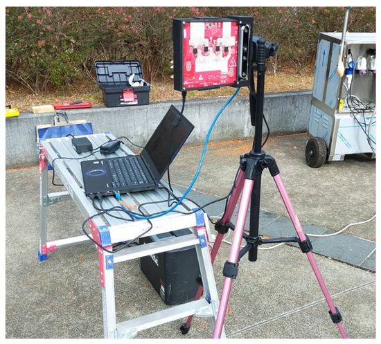
Figure 1.
The 79 GHz MIMO radar (TIDEP-01012) used in this study.
For MIMO radar, orthogonality of the transmitted waveforms is required to allow separation at the receiver [6]. There are several ways to achieve this orthogonality such as using different frequency, polarization, or phase coding schemes [6]. The TIDEP-01012 uses time division multiplexing (TDM), which transmits the signal sequentially with a certain time difference between each transmission. Note that the same signal waveform is used for all transmitters in the TIDEP-01012.
In FMCW radar, the transmitted chirp parameters such as chirp rate, sweep time, and start frequency of the chirp determine the frequency bandwidth and center frequency, followed by the determination of the range resolution and the maximum observable range (unambiguous range). TIDEP-01012 provides large flexibility in configuring these chirp parameters as well as the timing of the chirp transmission.
The FMCW MIMO radar imaging is simply performed using the 2D Fourier transform in range and azimuth direction with some approximations [40].
Table 1 summarizes the technical features of the used MIMO radar determined using the configured chirp parameters.

Table 1.
Technical details of the radar systems used in the experiments.
3.2. 17 GHz GB-SAR
The deployed GB-SAR system is the FastGB-SAR (Metasensing, Noordwijk, The Netherlands) developed by Metasensing [41], as shown in Figure 2. This system is a Ku-band (17.2 GHz) FMCW radar capable of acquiring SAR data in 5 s. It consists of a radar sensor equipped with two transmit and two receive antennas (vertically and horizontally polarized) and a mechanical linear rail. Although not used in this study, the FastGB-SAR can acquire quad-polarimetric data for polarimetric SAR applications. This radar system uses standard-gain antennas with equal beamwidth in the azimuth and elevation planes, where the beamwidth in both directions is about .
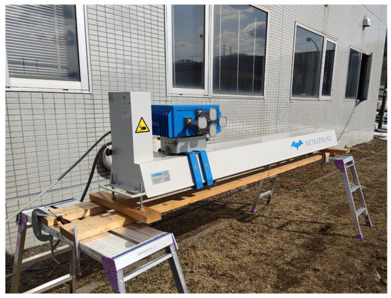
Figure 2.
The 17 GHz FMCW GB-SAR system (FastGB-SAR) used in this study.
The far-field pseudopolar format algorithm (FPFA) is used for 2D GB-SAR image reconstruction [40]. This algorithm allows image reconstruction using only 2D Fourier transform in azimuth and range direction with far-field approximation. Therefore, the same signal processing is applied in radar imaging as in the 79 GHz MIMO radar.
Table 1 summarizes the parameters used for FastGB-SAR monitoring in this study.
4. Experiments and Results
This section provides an overview of the performed experiments and the results obtained with two ground-based radar systems, i.e., the 79 GHz MIMO radar (hereafter referred to as 79 GHz radar) and the 17 GHz GB-SAR (hereafter referred to as 17 GHz radar). In this section, two types of outdoor measurements for about 1-day are reported to analyze the interferometric data under different weather conditions and site topography. The details of the experimental setup and configurations are demonstrated in the following.
4.1. Experiment over an Open Flat Field
The first experiment was conducted in an open flat field in Sendai, Japan, for about 24 h from 15:00 on 26 January 2023 to 15:05 on 27 January 2023 (JST). The purpose of the first experiment is to analyze the data under calm weather conditions and less topographic variation without any displacement phase component. In the analysis, APS is only evaluated on stable targets, assuming no displacement. Since natural targets are only trees and bushes over the tested field, we deployed nine trihedral corner reflectors as stable scatterers. Of the nine CRs, seven are triangular trihedral CRs and two are square trihedral CRs (SCRs). During the experiment, the field ground was covered with snow due to the snowfall observed before the experimental day, but no snowfall was observed during the observation period. Figure 3 shows the observation field, the deployed sensors, and the CRs. The weather station was installed beside the radar sensors to collect meteorological data at the sensor position with a time interval of 1 min. The 79 GHz radar observation data from 11:36 on the 27th to 12:20 on the 27th are missing because the system was unexpectedly aborted during this period.
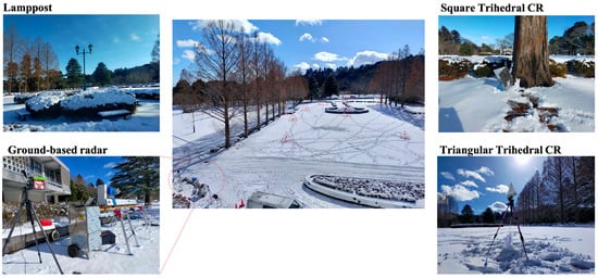
Figure 3.
Outdoor experiment at an open flat field in Sendai, Japan. Nine CRs were deployed as the evaluation targets. MIMO radar and GB-SAR were located at the same position. The weather station was installed beside the radar sensors. The positions of CRs and lamppost are indicated by triangles and a square, respectively.
The time interval between radar image acquisitions is set to 30 s for both radars. However, for the 79 GHz radar, an additional six radar images are acquired every 30 s for temporal averaging to improve the SNR. The averaged radar images over the entire observation period are shown in Figure 4. It can be seen from the measured images that the CRs and lamppost are well-focused and provide high backscatter intensity.
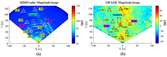
Figure 4.
Mean magnitude radar images averaged over the entire observation period. Triangles and rectangles indicate the location of CRs and a lamppost, respectively: (a) 79 GHz radar and (b) 17 GHz radar.
The CSs are selected based on the DA criterion in this experiment. Figure 5 shows the DA images from both radars. It can be seen that most of the pixels result in a high DA value of ~0.6 because they correspond to natural targets, while the CRs and lamppost result in a low DA value. Two different DA thresholds are used for the CS selection, where it is set to 0.3 for the 79 GHz radar and 0.25 for the 17 GHz radar.
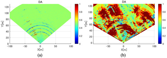
Figure 5.
DA images for the (a) 79 GHz radar and (b) 17 GHz radar.
Figure 6a–c shows the temporal variation in temperature, humidity, and pressure measured using the deployed weather station at the radar position. Given the meteorological data, the temporal APS variation at any range distance can be estimated using (8). The estimated cumulative APS time series at several slant range positions for two different operating frequencies are shown in Figure 6d,e.
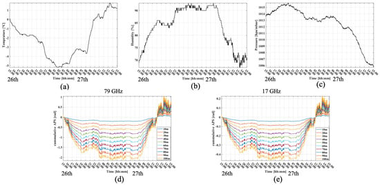
Figure 6.
Meteorological data collected from a weather station 1 min intervals and estimated APS for several slant range positions using the measured meteorological data. (a) Temperature; (b) humidity; (c) pressure; (d) estimated APS for = 79 GHz in radians; and (e) estimated APS for = 17 GHz in radians.
Figure 7a shows the displacement time series for the 79 GHz radar at CRs and lamppost without any APS compensation, while Figure 7b–e shows the compensated results using meteorological data (meteo-based correction) and the data-driven approach in (13) with three models, i.e., model-1, model-2, and model-3. In Figure 7, a positive displacement indicates the direction from the target to the sensor, and vice versa.
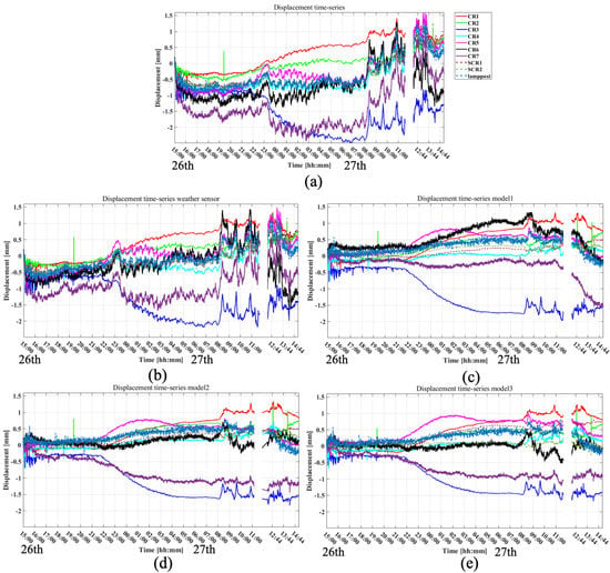
Figure 7.
Displacement time series at CRs and a lamppost estimated using 79 GHz radar data. (a) Results without APS compensation; (b) results after APS compensation using meteorological data; (c) results after APS compensation using model-1; (d) results after APS compensation using model-2; and (e) Results after APS compensation using model-3. In figures, we intentionally mask the part of the data that is missing.
As visually confirmed, the uncompensated displacement time series shows high-frequency fluctuation that could be caused by the APS effect. It is also shown that such fluctuations are not well compensated by the meteo-based correction. On the other hand, the compensation results using a data-driven approach yield less effect of the high-frequency component of the APS, indicating a reasonable compensation performance. However, low-frequency deviations are confirmed after data-driven compensation in Figure 7c–e, especially for CR1, CR3, CR5, and CR7, starting around 22:00 on the 26th. A plausible phenomenon causing such a deviation is the thermal expansion or shrinkage of the CR itself since it is made of aluminum. This assumption is supported by the temperature data shown in Figure 6a, where the temperature drops drastically around 22:00 on the 26th.
Similarly, Figure 8 shows the displacement time series results of the 17 GHz radar. Comparing the uncompensated displacement results of the 79 GHz and 17 GHz radars, the high-frequency variation is more pronounced in the 79 GHz radar data than in the 17 GHz radar. The low-frequency deviation found in the 79 GHz radar data is also evident in the 17 GHz radar displacement results.
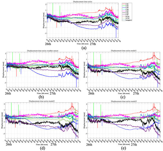
Figure 8.
Displacement time series at CRs and a lamppost estimated using 17 GHz radar data. (a) Results without APS compensation; (b) results after APS compensation using meteorological data; (c) results after APS compensation using model-1; (d) results after APS compensation using model-2; (e) results after APS compensation using model-3.
To quantify the amount of APS impact, the root mean square (RMS) and SD of the estimated displacements for both the 79 GHz and 17 GHz radars are plotted in Figure 9. Note that the bar plots are derived from the displacement results at nine CRs and one lamppost from 15:00 on the 26th to 21:00 on the 26th. The time series displacement from 21:00 on the 26th to the end are omitted to avoid the physical displacement of the CRs, which is assumed to be caused by thermal displacement.
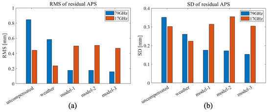
Figure 9.
RMS and SD of residual APS time series at CRs and a lamppost derived from Figure 7 and Figure 8. The blue and red bar plots represent the results from 79 GHz and 17 GHz, respectively. The bar plots are derived from the displacement results at nine CRs and one lamppost from 15:00 on the 26th to 21:00 on the 26th. (a) RMS bar plot and (b) SD bar plot.
The uncompensated results in Figure 9a show that the RMS and SD of the 79 GHz radar are higher than the 17 GHz radar. Such results are also obtained using meteorological data. On the other hand, the results of the data-driven approach show that the 79 GHz radar yields lower RMS and SD than the 17 GHz radar. In the 79 GHz radar result, improvements in the APS correction using the data-driven approaches are evident, where these show lower RMS and SD than the meteo-based correction.
4.2. Experiment over the Quarry
The second experiment was carried out in a quarry in Sendai, Japan. The monitoring campaign started at 17:44 on 24 January 2023 and ended at 16:05 on 25 January 2023. The second experiment aims to analyze the data acquired over steep topography with harsh weather conditions compared to the first experiment for a more realistic natural slope monitoring scenario.
Both radar systems were installed in front of the target slope and close to each other, as shown in Figure 10. Figure 11 shows the locations of the installed radars overlayed on an aerial image of the quarry monitoring site. The 79 GHz radar is tilted from the ground in elevation direction to maximize the backscatter intensity from the slopes, as shown in Figure 11b. Several CRs were installed over the illumination area, but some were found to have been moved by the wind. Therefore, it was decided to use only one CR for the evaluation. The location of the evaluated CR is indicated with a triangle in Figure 11a.
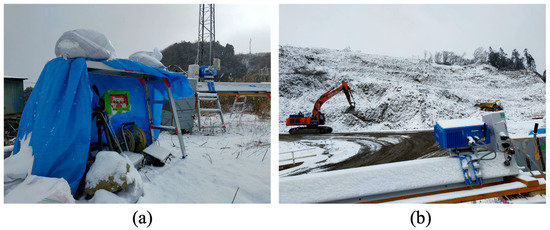
Figure 10.
Radar systems installed at Sendai quarry, Japan: (a) 79 GHz MIMO radar and (b) 17 GHz GB-SAR.
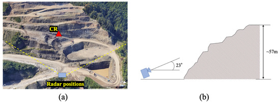
Figure 11.
(a) The location of the CR and radars overlayed on an aerial image showing the observation site (exported from Google Earth). A square and a triangle indicate the radar and CR locations, respectively. (b) Observation geometry.
During the measurement, snowfall was observed from around 4:00 am on the 25th. Continuous snowfall from the middle of the observation period changes the slope surface elevation due to snow accumulation. Figure 12 shows snow depth information during the observation period collected by the Automated Meteorological Data Acquisition System (AMeDAS) at the Sendai meteorological observatory near the study area.
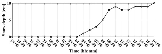
Figure 12.
Snow depth measured by AMeDAS at the Sendai meteorological observatory.
When observing the quarry site, a massive amount of noise is expected to be added to the received signal due to the passage of heavy machinery in the illuminated area. Such noise causes a phase unwrapping ambiguity, leading to the so-called phase jump [42]. This phase jump error appeared as a step-like sudden shift in the cumulative displacement results. Measured data from 79 GHz radar often contain phase jump errors, which are not observed in 17 GHz radar. As it is apparent that such phase jumps are caused by clutter rather than actual abrupt target displacement, manual corrections are made in this analysis.
Figure 13 shows mean magnitude radar images averaged over the entire observation period. In addition, the mean spatial coherence images are shown in Figure 14. Only the data set acquired before the snowfall event is used to derive the mean spatial coherence to avoid the low coherence data set affected by the snowfall.
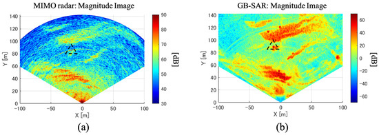
Figure 13.
Mean magnitude radar images averaged over the entire observation period. The triangle indicates the location of the analyzed CR: (a) 79 GHz radar and (b) 17 GHz radar.
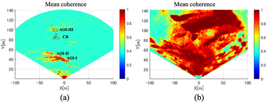
Figure 14.
Mean spatial coherence images averaged by acquisition data before the beginning of the snowfall event: (a) 79 GHz radar and (b) 17 GHz radar.
In the magnitude image of the 79 GHz radar, it can be seen that the intensity decreases as the slant range distance increases. As a result, very low coherence values are observed on the cliff surface more than 60 m apart from the sensor, as shown in Figure 14a. A narrower antenna 3-dB beamwidth in the elevation direction ( at 78 GHz) can be considered as one of the plausible reasons for this consequence in addition to the propagation loss. Such apparent decreases in magnitude and coherence are not observed in the 17 GHz radar data.
In addition to the CR, three areas of interest (AOI) over the slope surface are selected for further evaluation. These three AOI locations are shown in Figure 14a. By applying simple co-registration using the CR locations, a comparison can be made between the 79 GHz and 17 GHz radar images over the selected AOI.
Figure 15 shows the displacement time series at the CR for both radar data. Note that the CR is assumed to have no physical displacement during the observation period; therefore, only the APS signal is assumed to contribute to the phase variations in Figure 15. For the comparison, bar plots for the RMS and SD derived from the cumulative displacement in Figure 15 are shown in Figure 16.

Figure 15.
Displacement time series at the CR for both the uncompensated and compensated results: (a) 79 GHz radar and (b) 17 GHz radar.
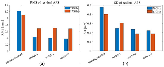
Figure 16.
RMS and SD of the residual APS time series at the CR derived from Figure 15. (a) RMS bar plot and (b) SD bar plot.
Figure 15 and Figure 16 show the effective reduction in the APS contribution after compensation for both radar results. The large difference between the compensation models can be seen in the APS time series. In particular, the model-1 results give a large deviation from the other models around 2:00 on the 24th for the 79 GHz radar and 5:00 on the 25th for the 17 GHz radar. As a result, the model-1 results give the largest SD among the models, implying the inhomogeneous refractivity distribution along the propagation path. The model-2 and model-3 results show better compensation performance than model-1 in the second experiment.
According to Figure 16, the uncompensated results for both radars show higher RMS and SD than those of the first experiment, shown in Figure 9, indicating a larger APS contribution for the second experiment than the first experiment. Comparing the results of the two radars, the uncompensated result of the 79 GHz radar shows higher RMS and SD than that of the 17 GHz radar, while the compensated results of the 79 GHz radar yield lower RMS than those of the 17 GHz radar.
Finally, Figure 17 and Figure 18 show the displacement time series obtained at the three selected AOIs. These time series results show the averaged displacement over the pixels corresponding to the same AOI. As for the compensation results, the data-driven compensation with model-3 is applied as it shows the best correction performance based on the CR data. From the results, the plots show a trend change around the time of snowfall (indicated with a dotted line) after APS compensation, which may indicate surface elevation change effects due to snow accumulation.
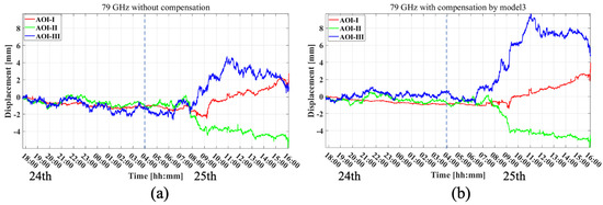
Figure 17.
Displacement time series at three selected AOIs (locations are shown in Figure 14a) obtained with the 79 GHz radar. The dotted line indicates the timing of the beginning of the snowfall. (a) Results without any APS compensation and (b) results after APS compensation using model-3.
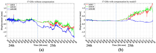
Figure 18.
Displacement time series at three selected AOIs obtained with the 17 GHz radar. The dotted line indicates the time of the beginning of the snowfall. (a) Results without any APS compensation and (b) results after APS compensation using model-3.
5. Discussion
We investigated the impact of the APS in 79 GHz radar interferometry in the application of slope monitoring and the potential method to reduce the APS effect using two outdoor field measurements. The evaluation was carried out using displacement time series results at CR or lamppost positions. Two field experiments revealed higher APS effects in the uncompensated displacement time series of the 79 GHz radar data than those of the 17 GHz radar in terms of RMS and SD. Nevertheless, the experiments showed that data-driven APS correction reduced the RMS and SD of the 79 GHz radar, resulting in a lower RMS of the 79 GHz radar than the 17 GHz radar. These results suggest that 79 GHz has the potential to measure displacements with an accuracy comparable to that of 17 GHz in the configuration and environment tested, i.e., medium range (~140 m) in a harsh environment.
In our experiment, several APS correction approaches were tested. The differences in correction performance are mainly due to different assumptions about the spatial distribution of atmospheric refractivity. When there is an inhomogeneous distribution of refractivity over the illumination field, correction methods that assume homogeneity, such as the data-driven approach using model-1 and the meteo-based correction, result in a biased estimate of the APS. According to the results for the 79 GHz radar, the best improvements in RMS and SD are obtained using model-3 in both fields. This implies the existence of an inhomogeneous distribution in the refractivity during the measurement period. Comparing the meteo-based correction and the data-driven approaches in the first experiment, the data-driven approach gave better correction performance than the meteo-based correction. The small improvement in the meteo-based correction suggests that the meteorological data at one location were not representative of the conditions over the observed field.
However, it should be noted that the data-driven approach applied to the 17 GHz radar data in the first experiment leads to an increase in the RMS and SD. On the other hand, the 17 GHz radar data in the second experiment show a large improvement from the data-driven approach. Although it is unclear why there is no improvement in the 17 GHz radar results using the data-driven approach in the first experiments, our observations suggest large differences in performance between the two radar systems, which could be caused by differences in APS impacts, coherence, and spatial resolution. Therefore, a careful selection of the APS correction approach must be made for each monitoring campaign to achieve the best performance. This suggests that further intensive analysis is required by performing a larger number of verification measurements under more diverse meteorological and topographic conditions.
Finally, the second experiment demonstrates the potential of measuring snow accumulation with both radar systems. Although the two radars show an apparent trend change in the estimated displacement from the expected time that the snowfall began, large gaps in the temporal behavior between the two radar results are observed. In particular, the 79 GHz radar data show a negative displacement direction (sensor to target direction) in AOI-II, which is contrary to the expectation that the snow accumulation is supposed to show a positive direction. Phase ambiguity caused by phase wrapping is a plausible reason for such phenomena. It occurs when the target displacement between two radar observations exceeds (0.95 mm).
To demonstrate the effect of phase wrapping on displacement estimation, we perform a simple simulation. In the simulation, we generate 1000 interferometric phase samples for the two operating frequencies of 17 GHz and 79 GHz, where the phase values for each sample correspond to a displacement of 0.5 mm. Therefore, no phase wrapping is observed from the generated phase stack as it does not exceed for the operating frequency of both radars. To simulate phase ambiguity, we add the phase value corresponding to 0.5 mm to randomly selected simulated samples. This results in some samples having phase values equal to 1 mm, resulting in phase wrap only at 79 GHz. We then estimate the displacement values using the cumulative sum of the wrapped interferometric phase stack, as shown in Figure 19. Figure 19 shows the results of four situations where we test different numbers of ambiguity samples: 1%, 10%, 30%, and 80% of all samples. According to the results, a larger gap between two radars is observed for the simulation with a higher number of ambiguity samples. In Figure 19d, the displacement of 79 GHz even shows an opposite direction or sign to that of 17 GHz. Such a phenomenon is expected in the second experiment. The straightforward solution to the wrapping issue is to minimize the temporal baseline. Such a proper observation design can further lead to an accurate inversion of the displacement.
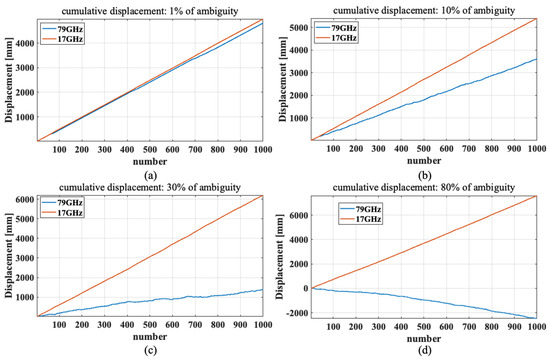
Figure 19.
Displacement results estimated from the simulated 1000 phase samples, some of which show phase wrap at 79 GHz. The number of ambiguity samples (percentage of all samples) is varied at (a) 1%; (b) 10%; (c) 30%; and (d) 80%.
6. Conclusions
The present work investigated the impact of APS and its potential correction methods in 79 GHz ground-based radar interferometry, in particular, for slope monitoring applications. The portable and cost-effective MIMO radar was investigated as the 79 GHz ground-based radar system. In order to compare the APS effects and correction performance between two different operating frequencies of the systems, the 17 GHz GB-SAR was jointly used in the experiments.
Two types of one-day outdoor experiments were conducted, one in an open flat field and the other in a topographically varied query site with very different weather conditions. Continuous snowfall was observed from the middle of the observation period at the quarry site.
Several APS corrections were tested in the analysis, including meteo-based correction and data-driven approaches. For the data-driven approach, the three models were applied, assuming homogeneity or inhomogeneity in the refractivity distribution depending on the model.
The observation results showed that the uncompensated 79 GHz radar resulted in larger APS impacts than those of the 17 GHz radar in terms of RMS and SD. On the other hand, the data-driven correction methods of the three selected models resulted in a lower RMS of the 79 GHz radar than the 17 GHz radar, while the meteo-based correction did not. Although no large differences in correction performance were observed between the models, model-3 yielded the lowest RMS and SD in the performed experiments. Furthermore, our monitoring showed the displacement over the quarry slope caused by snow accumulation for both radar systems.
Further intensive analysis is required by carrying out a larger number of verification measurements under more varied meteorological and topographical conditions. However, our preliminary study suggests that an accurate displacement measurement with a 79 GHz ground-based radar comparable to 17 GHz is possible with the appropriate APS correction, demonstrating the potential use of a 79 GHz ground-based interferometer for natural slope monitoring.
Author Contributions
Conceptualization, Y.I.; methodology, Y.I.; software, Y.I.; validation, Y.I.; formal analysis, Y.I.; investigation, Y.I; resources, Y.I.; data curation, Y.I.; writing—original draft preparation, Y.I.; writing—review and editing, Y.I.; visualization, Y.I.; supervision, M.S. All authors have read and agreed to the published version of the manuscript.
Funding
This research was funded by the governmental subsidy “Supporting Industry” for R&D projects of small-medium scale manufacturers in Japan.
Acknowledgments
The authors would like to thank Ryuma Saito and Tsogtbaatar Amarsaikhan for their assistance during the radar measurements and initial radar setup. The authors would also like to thank Sendai Saiseki Ltd. for providing the quarry field measurement opportunity.
Conflicts of Interest
The authors declare no conflict of interest.
References
- Gabriel, A.K.; Goldstein, R.M.; Zebker, H.A. Mapping small elevation changes over large areas: Differential radar interferometry. J. Geophys. Res. Atmos. 1989, 94, 9183–9191. [Google Scholar] [CrossRef]
- Perissin, D.; Wang, T. Time-Series InSAR Applications Over Urban Areas in China. IEEE J. Sel. Top. Appl. Earth Obs. Remote Sens. 2011, 4, 92–100. [Google Scholar] [CrossRef]
- Caduff, R.; Schlunegger, F.; Kos, A.; Wiesmann, A. A review of terrestrial radar interferometry for measuring surface change in the geosciences. Earth Surf. Process. Landf. 2015, 40, 208–228. [Google Scholar] [CrossRef]
- Pieraccini, M.; Miccinesi, L. Ground-Based Radar Interferometry: A Bibliographic Review. Remote Sens. 2019, 11, 1029. [Google Scholar] [CrossRef]
- Pieraccini, M.; Miccinesi, L. ArcSAR: Theory, Simulations, and Experimental Verification. IEEE Trans. Microw. Theory Tech. 2017, 65, 293–301. [Google Scholar] [CrossRef]
- Tarchi, D.; Oliveri, F.; Sammartino, P.F. MIMO Radar and Ground-Based SAR Imaging Systems: Equivalent Approaches for Remote Sensing. IEEE Trans. Geosci. Remote Sens. 2012, 51, 425–435. [Google Scholar] [CrossRef]
- Michelini, A.; Coppi, F.; Bicci, A.; Alli, G. SPARX, a MIMO Array for Ground-Based Radar Interferometry. Sensors 2019, 19, 252. [Google Scholar] [CrossRef]
- Sammartino, P.F.; Tarchi, D.; Baker, C.J. MIMO Radar Topology: A Systematic Approach to the Placement of the Antennas. In Proceedings of the 2011 International Conference on Electromagnetics in Advanced Applications, ICEAA’11, Torino, Italy, 12–16 September 2011. [Google Scholar]
- Hu, C.; Wang, J.; Tian, W.; Zeng, T.; Wang, R. Design and Imaging of Ground-Based Multiple-Input Multiple-Output Synthetic Aperture Radar (MIMO SAR) with Non-Collinear Arrays. Sensors 2017, 17, 598. [Google Scholar] [CrossRef]
- Zhuge, X.; Yarovoy, A. Sparse multiple-input multiple-output arrays for high-resolution near-field ultra-wideband imaging. IET Microw. Antennas Propag. 2011, 5, 1552–1562. [Google Scholar] [CrossRef]
- Pieraccini, M.; Miccinesi, L. An Interferometric MIMO Radar for Bridge Monitoring. IEEE Geosci. Remote Sens. Lett. 2019, 16, 1383–1387. [Google Scholar] [CrossRef]
- Mugnai, F.; Tarchi, D. Multiple-input multiple-output radar, ground-based MIMO SAR for ground deformation monitoring. Eur. J. Remote Sens. 2022, 55, 604–621. [Google Scholar] [CrossRef]
- Deng, Y.; Hu, C.; Tian, W.; Zhao, Z. A Grid Partition Method for Atmospheric Phase Compensation in GB-SAR. IEEE Trans. Geosci. Remote Sens. 2022, 60, 5206713. [Google Scholar] [CrossRef]
- Baumann-Ouyang, A.; Butt, J.A.; Varga, M.; Wieser, A. MIMO-SAR Interferometric Measurements for Wind Turbine Tower Deformation Monitoring. Energies 2023, 16, 1518. [Google Scholar] [CrossRef]
- Gale, S.; Farrington, L.; Bergström, P.; Suikkanen, M.; Boldrini, N.; Rubino, M.; Coli, N.; Naude, S.; Stopka, C.J.; Preston, C. Monitoring Applications for Safe Mining Practices: Case Studies of Sub-Bench Scale Failures in Hard Rock and Coal Open Cut Mines. In Proceedings of the 2020 International Symposium on Slope Stability in Open Pit Mining and Civil Engineering, Perth, Australia, 12–14 May 2020; pp. 1563–1576. [Google Scholar]
- Miccinesi, L.; Consumi, T.; Beni, A.; Pieraccini, M. W-band MIMO GB-SAR for Bridge Testing/Monitoring. Electronics 2021, 10, 2261. [Google Scholar] [CrossRef]
- Hosseiny, B.; Amini, J.; Aghababaei, H. Structural displacement monitoring using ground-based synthetic aperture radar. Int. J. Appl. Earth Obs. Geoinf. 2023, 116, 103144. [Google Scholar] [CrossRef]
- Texas Instruments Imaging Radar Using Cascaded MmWave Sensor Reference Design (Rev. A). Available online: https://www.ti.com/tool/ja-jp/TIDEP-01012 (accessed on 1 June 2023).
- Baumann-Ouyang, A.; Butt, J.A.; Salido-Monzú, D.; Wieser, A. MIMO-SAR Interferometric Measurements for Structural Monitoring: Accuracy and Limitations. Remote Sens. 2021, 13, 4290. [Google Scholar] [CrossRef]
- Karunathilake, A.; Sato, M. Atmospheric Phase Compensation in Extreme Weather Conditions for Ground-Based SAR. IEEE J. Sel. Top. Appl. Earth Obs. Remote Sens. 2020, 13, 3806–3815. [Google Scholar] [CrossRef]
- Luzi, G.; Pieraccini, M.; Mecatti, D.; Noferini, L.; Guidi, G.; Moia, F.; Atzeni, C. Ground-based radar interferometry for landslides monitoring: Atmospheric and instrumental decorrelation sources on experimental data. IEEE Trans. Geosci. Remote Sens. 2004, 42, 2454–2466. [Google Scholar] [CrossRef]
- Dematteis, N.; Luzi, G.; Giordan, D.; Zucca, F.; Allasia, P. Monitoring Alpine glacier surface deformations with GB-SAR. Remote Sens. Lett. 2017, 8, 947–956. [Google Scholar] [CrossRef]
- Iglesias, R.; Fabregas, X.; Aguasca, A.; Mallorqui, J.J.; Lopez-Martinez, C.; Gili, J.A.; Corominas, J. Atmospheric Phase Screen Compensation in Ground-Based SAR With a Multiple-Regression Model Over Mountainous Regions. IEEE Trans. Geosci. Remote Sens. 2014, 52, 2436–2449. [Google Scholar] [CrossRef]
- Baffelli, S.; Frey, O.; Hajnsek, I. Geostatistical Analysis and Mitigation of the Atmospheric Phase Screens in Ku-Band Terrestrial Radar Interferometric Observations of an Alpine Glacier. IEEE Trans. Geosci. Remote Sens. 2020, 58, 7533–7556. [Google Scholar] [CrossRef]
- Izumi, Y.; Frey, O.; Baffelli, S.; Hajnsek, I.; Sato, M. Efficient Approach for Atmospheric Phase Screen Mitigation in Time Series of Terrestrial Radar Interferometry Data Applied to Measure Glacier Velocity. IEEE J. Sel. Top. Appl. Earth Obs. Remote Sens. 2021, 14, 7734–7750. [Google Scholar] [CrossRef]
- Hu, C.; Deng, Y.; Tian, W.; Zhao, Z. A Compensation Method for a Time–Space Variant Atmospheric Phase Applied to Time-Series GB-SAR Images. Remote Sens. 2019, 11, 2350. [Google Scholar] [CrossRef]
- Cao, W.; Mao, Y.; Wei, L.; He, L.; Zhao, Z. Atmospheric Phase Screen Compensation of GB-SAR in Deep Dagushan Open-Pit Mine. IEEE Geosci. Remote Sens. Lett. 2022, 19, 4009905. [Google Scholar] [CrossRef]
- Zhu, Y.; Xu, B.; Li, Z.; Li, J.; Hou, J.; Mao, W. Joint Estimation of Ground Displacement and Atmospheric Model Parameters in Ground-Based Radar. Remote Sens. 2023, 15, 1765. [Google Scholar] [CrossRef]
- Izumi, Y.; Nico, G.; Sato, M. Time-Series Clustering Methodology for Estimating Atmospheric Phase Screen in Ground-Based InSAR Data. IEEE Trans. Geosci. Remote Sens. 2022, 60, 5206309. [Google Scholar] [CrossRef]
- Pipia, L.; Fabregas, X.; Aguasca, A.; Lopez-Martinez, C. Atmospheric Artifact Compensation in Ground-Based DInSAR Applications. IEEE Geosci. Remote Sens. Lett. 2008, 5, 88–92. [Google Scholar] [CrossRef]
- Noferini, L.; Pieraccini, M.; Mecatti, D.; Luzi, G.; Atzeni, C.; Tamburini, A.; Broccolato, M. Permanent scatterers analysis for atmospheric correction in ground-based SAR interferometry. IEEE Trans. Geosci. Remote Sens. 2005, 43, 1459–1471. [Google Scholar] [CrossRef]
- Huang, Z.; Sun, J.; Li, Q.; Tan, W.; Huang, P.; Qi, Y. Time- and Space-Varying Atmospheric Phase Correction in Discontinuous Ground-Based Synthetic Aperture Radar Deformation Monitoring. Sensors 2018, 18, 3883. [Google Scholar] [CrossRef]
- Iglesias, R.; Aguasca, A.; Fabregas, X.; Mallorqui, J.J.; Monells, D.; Lopez-Martinez, C.; Pipia, L. Ground-Based Polarimetric SAR Interferometry for the Monitoring of Terrain Displacement Phenomena–Part I: Theoretical Description. IEEE J. Sel. Top. Appl. Earth Obs. Remote Sens. 2015, 8, 980–993. [Google Scholar] [CrossRef]
- Ferretti, A.; Prati, C.; Rocca, F. Permanent scatterers in SAR interferometry. IEEE Trans. Geosci. Remote Sens. 1999, 39, 1528–1530. [Google Scholar] [CrossRef]
- Smith, E.K.; Weintraub, S. The Constants in the Equation for Atmospheric Refractive Index at Radio Frequencies. Proc. IRE 1953, 41, 1035–1037. [Google Scholar] [CrossRef]
- Noferini, L.; Mecatti, D.; Macaluso, G.; Pieraccini, M.; Atzeni, C. Monitoring of Belvedere Glacier using a wide angle GB-SAR interferometer. J. Appl. Geophys. 2009, 68, 289–293. [Google Scholar] [CrossRef]
- Izumi, Y.; Zou, L.; Kikuta, K.; Sato, M. Iterative Atmospheric Phase Screen Compensation for Near-Real-Time Ground-Based InSAR Measurements Over a Mountainous Slope. IEEE Trans. Geosci. Remote Sens. 2020, 58, 5955–5968. [Google Scholar] [CrossRef]
- Wang, W.-Q. Virtual Antenna Array Analysis for MIMO Synthetic Aperture Radars. Int. J. Antennas Propag. 2012, 2012, 587276. [Google Scholar] [CrossRef]
- Texas Instruments. AWRx Cascaded Radar RF Evaluation Module. Available online: https://www.ti.com/cn/lit/ug/swru553a/swru553a.pdf (accessed on 1 June 2023).
- Fortuny-Guasch, J. A Fast and Accurate Far-Field Pseudopolar Format Radar Imaging Algorithm. IEEE Trans. Geosci. Remote Sens. 2009, 47, 1187–1196. [Google Scholar] [CrossRef]
- Rodelsperger, S.; Coccia, A.; Vicente, D.; Meta, A. Introduction to the new metasensing ground-based SAR: Technical description and data analysis. In Proceedings of the 2012 IEEE International Geoscience and Remote Sensing Symposium, Munich, Germany, 22–27 July 2012; pp. 4790–4792. [Google Scholar] [CrossRef]
- Michel, C.; Keller, S. Advancing Ground-Based Radar Processing for Bridge Infrastructure Monitoring. Sensors 2021, 21, 2172. [Google Scholar] [CrossRef]
Disclaimer/Publisher’s Note: The statements, opinions and data contained in all publications are solely those of the individual author(s) and contributor(s) and not of MDPI and/or the editor(s). MDPI and/or the editor(s) disclaim responsibility for any injury to people or property resulting from any ideas, methods, instructions or products referred to in the content. |
© 2023 by the authors. Licensee MDPI, Basel, Switzerland. This article is an open access article distributed under the terms and conditions of the Creative Commons Attribution (CC BY) license (https://creativecommons.org/licenses/by/4.0/).