Abstract
As in oceans, large-scale coherent circulations such as gyres and eddies are ubiquitous features in large lakes that are subject to the Coriolis force. They play a crucial role in the horizontal and vertical distribution of biological, chemical and physical parameters that can affect water quality. In order to make coherent circulation patterns evident, representative field measurements of near-surface currents have to be taken. This, unfortunately, is difficult due to the high spatial and temporal variability of gyres/eddies. As a result, few complete field observations of coherent circulation in oceans/lakes have been reported. With the advent of high-resolution satellite imagery, the potential to unravel and improve the understanding of mesoscale and submesoscale processes has substantially increased. Features in the satellite images, however, must be verified by field measurements and numerical simulations. In the present study, Sentinel-1 SAR satellite imagery was used to detect gyres/eddies in a large lake (Lake Geneva). Comparing SAR images with realistic high-resolution numerical model results and in situ observations allowed for identification of distinct signatures of mesoscale gyres, which can be revealed through submesoscale current patterns. Under low wind conditions, cyclonic gyres manifest themselves in SAR images either through biogenic slicks that are entrained in submesoscale and mesoscale currents, or by pelagic upwelling that appears as smooth, dark elliptical areas in their centers. This unique combination of simultaneous SAR imagery, three-dimensional numerical simulations and field observations confirmed that SAR imagery can provide valuable insights into the spatial scales of thus far unresolved mesoscale and submesoscale processes in a lake. Understanding these processes is required for developing effective lake management concepts.
1. Introduction
In large lakes subject to the Coriolis force, basin-scale/mesoscale gyres are known to dominate the kinetic energy of lake circulation and to play a key role in the horizontal and vertical distributions of physical, chemical and biological parameters throughout the lake [1,2]. These rotating coherent structures are primarily driven by wind and are modified by the Coriolis force [3,4,5,6], and can be affected by the irregularity of the lake basin and the surrounding topography. Such large lakes can be expected to exhibit a complex combination of counterclockwise (cyclonic) and clockwise (anticyclonic) gyres/eddies [7,8,9] in the northern hemisphere (opposite in the southern hemisphere). Cyclonic gyres are characterized by positive vorticity and a high-pressure core, whereas anticyclonic gyres are characterized by negative vorticity and a low-pressure core. Pressure gradients induced by cyclonic/anticyclonic gyres cause a decrease/increase in water surface elevation at their centers [10,11].
Cyclonic and anticyclonic circulations can form, respectively, a dome-shaped or bowl-shaped thermocline at their centers [12,13]. These upward or downward motions of the thermocline layer may strongly modify the physical (e.g., temperature and pollution) and chemical (e.g., water chemical composition and salinity) conditions of the water column, which in turn can affect biological processes such as phytoplankton growth and bacterial life cycles [12]. The identification of upwelling/downwelling zones can aid in understanding submesoscale/mesoscale biological, chemical and physical interactions in lakes and oceans.
The high spatiotemporal variability of submesoscale/mesoscale gyres/eddies in seas and oceans makes satellite imagery an appropriate tool for observing the size and distribution of such coherent circulations [6,14,15,16]. In particular, Synthetic Aperture Radar (SAR) imagery is often used to detect mesoscale/submesoscale circulation patterns (e.g., [17,18,19,20,21]). SAR imagery provides a two-dimensional (2D) picture of the spatial variation in sea surface roughness and measures the backscattered radar power or the Normalized Radar Cross Section (NRCS), measured in decibels, dB. NRCS values are affected by several factors, including wind speed and direction, incident angle and radar parameters. Under favorable wind conditions, SAR images can reveal characteristic footprints of phenomena in the upper ocean and in the lower atmospheric boundary layers [22].
The effect of different physical and biological parameters on the variation of NRCS values was examined previously. Using ERS-2 (European Remote-Sensing Satellite) SAR data, Clemente-Colón and Yan [23,24] found a relationship of 0.66 dB°C−1 between NRCS values and Sea Surface Temperature (SST) over coastal upwelling zones. Gurova and Ivanov [25] demonstrated that there is a strong correlation between patterns observed in SAR, SST, and optical sensors in coastal upwelling areas. They found that temperature anomalies in SST were accompanied by dark (low backscattering) or bright (high backscattering) signatures on SAR imagery. In theory, it is well established that SST anomalies caused by upwelling can increase the stability of the air-water boundary layer and reduce the surface water viscosity, thereby decreasing the roughness of the water surface in the upwelling zones [26,27,28]. The reduction of NRCS due to an increase in air–water stability over the upwelling zone is typically smaller than 3 dB [29,30].
The presence and accumulation of biogenic surfactants, i.e., surface-active substances, in the surface microlayer can significantly affect the roughness of the water surface and, therefore, affect or reveal patterns in SAR images. Surfactants alter water surface tension by suppressing short wind waves and thus reduce the radar backscatter cross-section [31,32]. Surfactants are often trapped and concentrated inside flow convergence lines, creating smooth (dark) surfaces in SAR images, referred to as natural slicks or films. Transport processes associated with eddies and gyres can cause slicks to form irregular spiral structures, which can be detected in SAR images [33,34,35,36]. Eddies identified by slick streaks are referred to as ‘black’ eddies [17,37]. In the presence of surfactants, the effect of SST on the NRCS is secondary [23,30].
The manifestation of eddies by natural biogenic surfactant films in a SAR image is generally influenced by wind speed. At higher wind speeds (~5–6 m s−1), wind-induced mixing in the upper layer will be strong and redistribute surface slicks, thus preventing the damping mechanism caused by the presence of surfactants [38,39]. In low to moderate wind speed (~2–6 m s−1) conditions, smooth surfactant-rich slicks and rough/rippled areas with low surfactant concentrations can be distinguished in SAR images [36]. Backscatter contrast induced by natural films can reach 5-10 dB in a SAR image [40]. Surfactants are mainly derived from biological sources, such as phytoplankton metabolic byproducts [41], marine bacterial activity [42], zooplankton grazing [43] and terrestrial sources [44] introduced by catchments around inland waters. In SAR imagery, chlorophyll concentration is often considered a proxy for detecting the spatial variability of surfactants [45,46]. According to Lin et al. [28], the reduction of NRCS values in SAR images is highly correlated with the increase in chlorophyll-a concentrations. It was reported that a 1 mg m−3 increase in chlorophyll-a concentration results in a reduction of 5 dB in NRCS values. Gurova and Ivanov [25] reported a change in NRCS values in an area with a high concentration of floating cyanobacteria. Thus, the spatial variability associated with natural films observed in SAR imagery can serve as an indicator of the different biological activities of different water masses [28].
In SAR images, bright curved lines may appear at higher wind speeds (>6 m/s) as a result of the interaction between surface waves and converging/shearing currents. The bright lines outline the shape of submesoscale/mesoscale eddies. Eddies manifested by this mechanism are referred to as ‘white’ eddies [15,17,34]. Existing algorithms for detecting eddies in SAR imagery are generally designed to identify ‘white’ or ‘black’ eddies. In previous studies, however, two other mechanisms were proposed for detecting eddies in a SAR image: (i) the variation of the wind field over an oceanic temperature front due to changes in the atmospheric boundary layer (e.g., [17,47]) and (ii) the presence of visible particles, such as ice (e.g., [48]). SAR imagery can provide valuable and unique information with high spatial resolution and a wide coverage under favorable wind conditions. However, it should be noted that several atmospheric processes, such as small-scale inhomogeneities of the near-surface wind field, wind shading, atmospheric convection, atmospheric gravity waves as well as precipitation can influence the patterns observed in SAR imagery. To improve the interpretation of submesoscale/mesoscale processes observed in SAR images, a multidisciplinary approach involving in situ observations, remote sensing and numerical modeling should be employed.
Although SAR imagery has been widely used to study submesoscale/mesoscale currents in seas and oceans, it has rarely been applied to study lake currents (e.g., [49,50,51]). Large lakes subject to the Coriolis force, such as Lake Geneva, are characterized by complex large-scale rotational current patterns [51], and thus 2D high-resolution SAR imagery can provide new insights into these mesoscale/submesoscale processes. Natural slicks, which contain a higher concentration of biogenic surfactants than rough surface areas, are ubiquitous in Lake Geneva [52], and can be observed under light to moderate wind speeds ranging from 1.5 to 5 m s−1. Detecting and monitoring large-scale currents in Lake Geneva using SAR imagery thus appears feasible. Indeed, we show that cyclonic gyres can manifest themselves in SAR images (i) through biogenic slicks, entrained in submesoscale and mesoscale currents (‘black’ eddies), and (ii) by pelagic upwelling, evidenced by smooth, dark elliptical areas in their centers. To investigate such features, the present study combines C-band SAR images from satellites Sentinel-1A and Sentinel-1B with in situ observations and results of high-resolution validated three-dimensional (3D) numerical model simulations of Lake Geneva under low wind conditions. This allowed for the first time in a lake to link surface observations of mesoscale gyres and submesoscale eddies to their vertical structure in the water column below.
The remaining sections of this paper are organized as follows: The study site, 3D numerical modeling, field campaigns and physical background of cyclonic eddies/gyres are described in Section 2. Field observations, numerical results and SAR images are compared in Section 3. The results are discussed in Section 4. A brief summary and conclusions are given in Section 5, followed by the Appendix A.
2. Materials and Methods
2.1. Study Area
Lake Geneva (France/Switzerland, local name: Lac Léman) is the largest lake in Western Europe (Figure 1). It is composed of two basins, the large, deep Grand Lac in the east (maximum depth 309 m), and the narrow, shallow Petit Lac in the west (maximum depth ~70 m). This crescent-shaped lake has a surface area of 580 km2, a volume of 89 km3 and a length of ~70 km along its main arc. Its maximum width is 14 km. It is surrounded by the Alps to the south and east, and the Jura mountains to the northwest. Two dominant wind fields, the Bise (coming from the northeast) and the Vent (coming from the southwest), are guided by the surrounding topography. The central and western parts of the lake are frequently subject to strong winds, which can last from several hours to several days. However, the surrounding high mountains shelter the eastern part of the lake from strong winds [53].
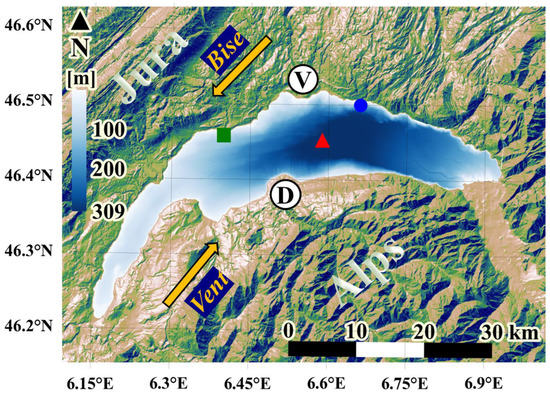
Figure 1.
Lake Geneva and surrounding topography. Red triangle: location of the long-term CIPEL monitoring station SHL2 where physical and biological parameters are measured. Green square: EPFL Buchillon Mast meteorological station (100-m offshore). Blue circle: LéXPLORE floating platform. The thick yellow arrows indicate the direction of the two strong dominant winds, called the Bise (coming from the northeast) and the Vent (coming from the southwest). V and D are the deltas of the Venoge and the Dranse rivers, respectively. These markers will be used in the figures below as reference points. The color legend describes the depth of the lake.
2.2. Synthetic Aperture Radar
Recent advances in satellite imaging technology have revolutionized our ability to observe basin-scale and submesoscale processes, thus allowing us to make significant progress in understanding how these processes are generated and how they develop in time and space. In particular, Synthetic Aperture Radar (SAR) has been applied successfully to detect oceanic and atmospheric features in marine boundary layers. SAR imagery has the following advantages: (i) it can be used in all weather conditions and at any time, (ii) it is highly sensitive to small-scale variability of the water surface, and (iii) it provides high-resolution images. The SAR dataset used in this study was obtained from the Sentinel-1A and Sentinel-1B satellites. These satellites are part of the European Space Agency’s (ESA) Copernicus program that provides C-band SAR observations. The co-polarized VV (vertical transmission; vertical reception) data are used because noise restricts the application of VH (vertical transmission; horizontal reception) data [54]. The primary reason for this is that surface water has a smaller radar cross-section in cross-polarized than in co-polarized channels (HH or VV) [55]. A comparison between VV and VH data obtained from Sentinel-1 SAR imagery is provided in Figure A1. This figure clearly shows that the VV data are significantly more sensitive to water surface roughness than the VH data. They capture surface pattern details that can be related to processes in the lake water column below, as will be demonstrated in the Results section. The spatial resolution of SAR data varies from 5 m to 20 m for a ground sampling distance of 10 m.
We used Level-1 Ground Range Detected (GRD) products that require denoising and correction prior to further analysis. Pre-processing of SAR GRD is performed according to the standard workflow proposed by [56]. In the pre-processing stage, the following seven steps are carried out: (1) the precise orbit state vectors for each SAR product are applied based on accurate satellite position and orbital speed; (2) additive thermal noise is reduced; (3) low-intensity noise and invalid data from the scene edges are eliminated; (4) digital pixels are used to generate radiometrically calibrated SAR backscatter; (5) SAR images are improved by reducing granular noise caused by waves reflected from other scatterers; (6) distortions caused by the side-looking geometry are corrected; and (7) the SAR backscatter coefficient is converted to decibels (dB) for postprocessing purposes.
2.3. Numerical Simulations
To study the 3D processes in cyclonic eddies/gyres, the Massachusetts Institute of Technology general circulation model (MITgcm; [57]) was used with a configuration similar to that employed by Cimatoribus et al. [58,59], who also performed an in-depth validation based on numerous field observations from around the lake. Using the current setup, Cimatoribus et al. [58,59] demonstrated that stratification, mean flow, and internal seiche variability in Lake Geneva can be realistically simulated. Hamze-Ziabari et al. [50,51] and Reiss et al. [60,61] showed that the model can accurately capture both submesoscale and basin/mesoscale processes in Lake Geneva. In all the cited studies, the modeled results compared well with field measurements.
The MITgcm code solves the 3D Boussinesq, hydrostatic Navier-Stokes equations (including the Coriolis force) [57]. Realistic atmospheric fields (such as wind, temperature, humidity, and solar radiation), extracted from the COnsortium for Small-scale MOdeling (COSMO) atmospheric model of MeteoSwiss with a resolution of 1 km, were used to force the lake surface [62]. Two Cartesian grids, a Low Resolution (LR) grid (horizontal resolution 173 to 260 m, 35 depth layers) and a High Resolution (HR) grid (horizontal resolution 113 m, 50 depth layers), were applied. The LR model was initialized from the rest using the temperature profile from the Commission Internationale pour la Protection des Eaux du Léman (CIPEL) station SHL2 [63] measured on 25 October 2017 and 19 December 2018, respectively (calm weather conditions prevailed on both dates). For each run, the LR model spin-up was ~180 d. Note that the LR results were only used to initialize the HR model. The layer thicknesses in the HR model ranged from 0.30 m at the surface to approximately 12 m for the deepest layer. The integration time step was 6 s.
2.4. Field Measurements
Guided by the numerical model results, four different transects were selected in the central part of the Grand Lac, where a cyclonic gyre and a submesoscale eddy were forecast [51]. Profiles spaced at 1 km and/or 500 m intervals were measured along the predefined transects. An ADCP (Acoustic Doppler Current Profiler, Teledyne Marine Workhorse Sentinel) equipped with a bottom-tracking module was used to measure the vertical profiles of current velocity at each point. Data were collected for at least 5 min at each point. The ADCP was set up for 100 1-m high bins (blanking distance of 2 m). The transducer was located at 0.5-m depth, and the high-resolution processing mode was chosen. Tilt and heading angles were derived from a built-in sensor.
Vertical profiles of water temperature were measured with a multiparameter probe (Sea and Sun Marine Tech) CTD75M at each predefined point during the September 2019 and October 2021 campaigns. The vertical speed of the CTD was approximately 10 cm s−1, with a measurement frequency of 7 Hz, giving a sampling resolution of about 1.5 cm.
2.5. Background Physics
In order to correctly interpret the geophysical data collected by microwave sensors such as SAR, it is important to understand not only the scattering physics, but also the hydrodynamic surface processes that influence the structure of surface water boundary layers [64]. The electromagnetic scattering from rough surfaces is typically described using an asymptotic approximation to an exact solution of Maxwell’s equations. A simplified scattering model developed by Elfouhaily et al. [65,66] is used here to demonstrate how backscatter in SAR images is related to lake-water surface roughness. According to [64,66], the scattered magnetic field, , at field point r can be expressed as
where k is the electromagnetic wave number, is the magnitude of the incident field, represents a polarization vector that defines the scattered field for an incident polarization state p, is the difference between the scattered and incident wave number vectors, and is the surface elevation at position . The subscripts H and z stand for the horizontal and vertical components, respectively.
The present study focuses on the physical and biological processes associated with basin-scale cyclonic gyres and how they can contribute to variations in (see Equation (1)) and, therefore, to backscattering signals. A schematic diagram of the processes associated with a cyclonic eddy/gyre is shown in Figure 2. An anticlockwise gyre in the northern hemisphere can cause divergence of the flow near the surface and convergence in the deeper layers (Figure 2). Consequently, upwelling occurs in the gyre’s center, and as a result, a dome-shaped thermocline forms. Based on the Boussinesq approximation and hydrostatic assumptions, the velocity field of a geostrophic flow field can be expressed as [67]
where u and v are horizontal velocities in the x and y directions, respectively, g is the acceleration due to gravity, 𝜌 is water density, and f is the Coriolis frequency. The first and second terms on the right sides of Equations (2) and (3) describe the baroclinic and barotropic contributions to u and v, respectively. The baroclinic terms result from the horizontal density gradient, whereas the barotropic terms result from the horizontal gradient of the water surface elevation. Pelagic upwelling induced by cyclonic circulation creates a horizontal density gradient between the center and periphery of the gyre. The gyre velocity drops to zero (i.e., ) in the presence of a strong thermocline in some deeper layers or at the lake bed. Consequently, the barotropic terms have to be opposed to the baroclinic terms according to Equations (2) and (3). The pelagic upwelling increases the baroclinic terms (water in the center is colder (denser) than in the periphery), which results in a decrease in the barotropic terms in the center of a cyclonic gyre. Therefore, a reduction in water surface elevation (η) takes place in the center of a cyclonic circulation.
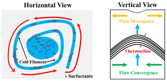
Figure 2.
Left panel: sketch of a cyclonic gyre (counterclockwise rotating; red arrows). Right panel: the associated upwelling of the thermocline in the center of the gyre (blue arrows).
Furthermore, wind stress can be affected by pelagic upwelling. In general, wind stress can be written as follows [68]:
where is the air density, is the wind speed at a height of 10 m and is the wind stress drag coefficient. The value of depends on the surface stability and the roughness length and can be expressed as [68,69,70]
where is a function representing the stability of the air-water interface, k is the von Kármán constant, L is the Monin-Obukhov length, and z0 is the surface roughness height. The stability parameter increases in the upwelling zone, thereby reducing the drag coefficient and wind stress in Equations (4) and (5) [22]. Low wind speeds lead to lower backscattering from the water surface.
The motion field of cyclonic gyres modifies its vertical thermal structure, causing an upward tilt of the thermocline and thus upwelling (upward water movement) in the center of the gyre (Figure 2). This vertical motion may enhance phytoplankton activity in the near surface layer. Upwelling-related biological processes may cause surfactant concentrations in the center of a gyre to vary, since phytoplankton metabolic byproducts are an important source of biogenic surfactants [41]. Due to their impact on water surface roughness, changes in surfactant concentration affect the backscattering of SAR signals. Local convergence zones and submesoscale cold filaments also often occur within eddies and gyres [35,50]. As shown in Figure 2, these processes can accumulate surfactants locally, thereby generating spatially variable SAR signals.
3. Results
In Lake Geneva, mesoscale and submesoscale circulations are generated by events of strong Bise and Vent winds that can last for several days. Thereafter, when winds have died down, numerical modeling predicts that these circulation patterns remain unchanged for several days. Below, we present examples of the circulation observed during these calm periods with very low wave activity. We will mainly compare the dynamics in September and in October. In September, the thermal stratification is strong and a thermocline is developed at ~10–15 m depth. These conditions are ideal for the formation of cyclonic gyres by wind energy in the shallow mixed layer. By the end of October, the mixed layer is deeper with a thermocline at ~30 m depth; the thermocline is also weaker than in September.
3.1. Biogenic Slicks Indicate the Presence of a Cyclonic Gyre
SAR images, unlike passive visible-range or infrared sensors, are characterized by patterns caused by changes in the roughness of the water surface. Traditionally, in SAR imagery, submesoscale/mesoscale eddies appear as ‘black’ eddy-like spirals consisting of several biogenic slick streaks or as ‘white’ eddies consisting of curved lines of high radar backscatter induced by wave/current interactions. The latter manifestation mechanism is not evident in the SAR images of Lake Geneva taken between 2018 and 2021. However, biogenic slick streaks that manifest submesoscale/mesoscale processes are observed frequently in Lake Geneva [50]. Figure 3a illustrates an example of a basin-scale gyre at the center of Lake Geneva on 21 July 2018. Unlike eddies found in oceans or seas, basin-scale gyres are constrained by the lake morphology, and their geometric shapes are influenced by the lake boundaries. As shown in Figure 3a, an elliptical eddy-like structure can be distinguished in the center of Lake Geneva. The simulated temperature and current velocity in the near-surface layer (0.3 m) are shown in Figure 3b (spatial resolution of 113 m). The current velocity confirms the presence of a cyclonic gyre in the center of Lake Geneva. Furthermore, several submesoscale cold and warm filaments can be detected in the surface temperature that wind into the center of the cyclonic gyre (Figure 3b). Similar frontal/filamentary patterns compare well with the SAR image taken on 21 July 2018 (Figure 3a).
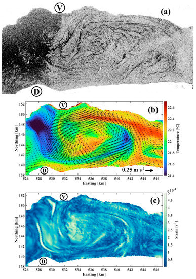
Figure 3.
(a) Subset of a Sentinel-1B SAR-C image acquired on 21 July 2018 at 17:31 UTC, (b) simulated temperature (color) and current velocity and direction (arrows) at 0.3-m depth, and (c) the horizontal strain rate (0.3-m depth), given by , from a high-resolution, 3D numerical simulation for 21 July 2018 at 18:00 UTC. In this expression, (u, v) are the (x, y) components of horizontal velocity field. Colorbars in (b,c) give the ranges of temperature and strain rate, respectively. V and D are reference points marked in Figure 1.
3.2. Signature of Pelagic Upwelling Induced by a Cyclonic Gyre
Figure 4a illustrates three distinct spatial patterns in the SAR image taken on 21 September 2019. A ‘dark’ elliptical region (marked CG in Figure 4a) surrounded by several dark slicks is seen at the center of the lake where numerical modeling predicted a cyclonic gyre. However, as shown in Figure 3a, the cyclonic gyre at the center of the lake usually appears with dark filamentary patterns winding into its center. On the other hand, a similar anticyclonic filamentary pattern with a large-scale eddy-like pattern at the western part of the lake (marked AG in Figure 4a) can be distinguished. Unlike the signature of cyclonic circulation observed in the center of the lake, the filamentary slicks are more concentrated at the edge and boundary of the lake and they do not spiral towards the center. A submesoscale eddy-like pattern (marked SE in Figure 4a) can be observed between two large-scale patterns in the central and western parts of the lake. The filamentary patterns move toward the center of the eddy, indicating a cyclonic circulation.
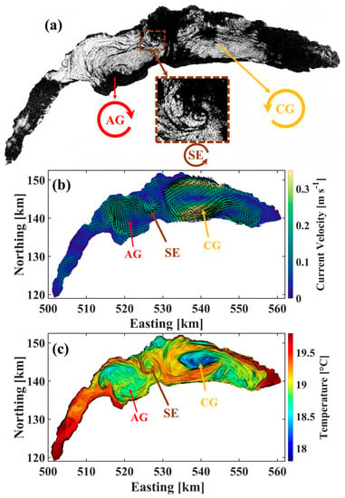
Figure 4.
(a) Sentinel-1A SAR-C image of Lake Geneva acquired on 20 September 2019 at 17:31 UTC. AG: anticyclonic gyre; CG: cyclonic gyre; SE: submesoscale eddy. (b) Simulated current velocity at 0.3-m depth (arrows: direction; color: velocity; colorbar legend: velocity range). (c) Simulated temperature (0.3-m depth; colorbar legend: temperature range) from a high-resolution, 3D numerical simulation for 20 September 2019 at 18:00 UTC. Easting and northing coordinates follow the Swiss CH1903 system.
The simulated velocity and temperature fields are shown in Figure 4b and c, respectively. The three different circulation patterns in the SAR image (AG, CG and SE) can be detected at almost the same locations in Figure 4b,c. An anticyclonic circulation with ~0.20 m s−1 current speed was predicted by the numerical model at the western part of the Lake where filamentary patterns were observed. The location of filamentary patterns is closely correlated with the distribution of current velocity. A small cyclonic circulation with the same size and at the same location as the cyclonic eddy in the SAR image was predicted by the model. Interestingly, a very strong cyclonic circulation (0.35 m s−1) is formed around the area where a ‘dark’ elliptical region is evident in the SAR image. The simulated temperature in the near-surface layer also shows cold upwelled water in the center of the cyclonic circulation that is 1.5–2 °C colder than the adjacent water. A horizontal filamentary pattern similar to the SAR image appears adjacent to the upwelling zone, in particular on its eastern side. A combination of cold and warm filamentary patterns is evident at the periphery of the anticyclonic gyre (AG) and at the center and periphery of the submesoscale cyclonic eddy (SE).
A SAR image taken on 20 September 2019 (Figure 5a) shows a similar ‘dark’ elliptical pattern but at a different location in the center of Lake Geneva. The numerical results confirm that the location of the center of cyclonic circulation is quite variable during its formation and that the pelagic upwelling location gradually moved from west to east (see Figure A2). A field campaign on 20 and 21 September 2019 was conducted at the center of the lake. Water temperatures at 1 m depth on four different transects (Figure 6a) were measured. Three transects, T1L, T1, and T1R, with 1.8–2 km distance between each other and consisting of 10 measurement points at 1 km intervals from south to north were measured on 20 September 2019 between ~07:15 and ~15:02 UTC (see Figure 6a for location of measurement points). The field measurements along each transect took almost 2 h. The measured near-surface temperatures along each transect are shown in Figure 6b,c. The temperature dropped by 1.2–2 °C at the center of each transect. The number of measurement points in which the drop in temperature was observed is different, mainly due to the elliptical shape of upwelling. The spatial and temporal variability of the upwelling zone is also different, since the transects were not measured at the same time. Measurements along transect T1L were taken between ~13:03 and ~15:02 UTC and are closest to the time of the SAR image on 20 September. As seen in Figure 6b, the center of upwelling (lowest temperatures) was located in the center of the lake near the area of the ‘dark’ elliptical zone in the SAR image.
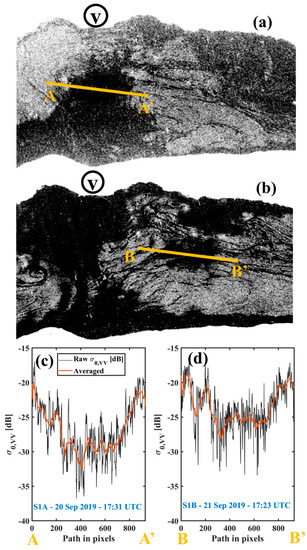
Figure 5.
(a) Subset of a Sentinel-1A SAR-C image acquired on 20 September 2019 at 17:31 UTC. (b) Subset of a Sentinel-1B SAR-C image acquired on 21 September 2019 at 17:23 UTC. Variation of NRCS along the transects (c) A–A’ (Sentinel-1A SAR-C image) and (d) B–B’ (Sentinel-1B SAR-C image). V and D: reference points marked in Figure 1.
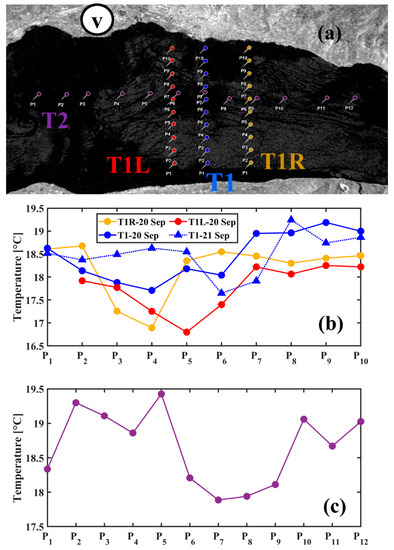
Figure 6.
(a) Subset of a Sentinel-1A SAR-C image acquired on 20 September 2019 at 17:31 UTC. (b) Near surface temperature (1 m depth) measured along transects T1L, T1 and T1R. (c) Near surface temperature (1 m depth) measured along transect T2. The distance between measurement points is ~1.5 km, whereas it is ~1 km along T1L, T1 and T1R. V: reference point marked in Figure 1.
On 21 September 2019, temperature measurements along transect T1 were repeated. Furthermore, a horizontal transect, T2, from east to west consisting of 12 points with a 1.5 km spacing was measured (see Figure 6a for the location of measurement points). As shown in Figure 5b, the cold area at the center of T1 moved toward the north compared to the day before. The drop in surface temperature by 1–1.5 °C was detected at two measurement points. However, the temperature drop along transect T2 occurred at four measurement points exactly where the ‘dark’ elliptical pattern was observed in the SAR image. The measurements along transect T2 were carried out between ~15:30 and ~18:30 UTC, which is close to 17:23 UTC when the SAR image was taken on 21 September. Note that other dark areas can be detected at different locations in both SAR images shown in Figure 4 and Figure 5. Low wind speeds (<~1.5–2 m s−1) can be responsible for such dark areas.
3.3. Submesoscale Eddies
In the SAR images, small eddies appear as radar-dark filaments wound into spirals. Submesoscale eddies can play an important role in lake/ocean turbulence, stratification, and primary production [51,71]. Field observations of such small structures are very rare in both oceans and lakes. However, Hamze-Ziabari et al. [51] demonstrated that these small eddies can be resolved in numerical simulations and that they can be measured in Lake Geneva. Following the same strategy as proposed by Hamze-Ziabari et al. [51], a field campaign was carried out on 26 October 2021 when both a SAR image and a submesoscale eddy between two gyres were expected. Therefore, fourteen measurement points with 500 m distance from each other (Figure 7a) were selected at the location of the expected eddy. The measurements along the transect shown in Figure 7a were taken between ~08:29 and ~11:07 UTC. A SAR image taken on 26 October at 5:43 UTC (Figure 7a) reveals an eddy-like structure containing several filamentary dark slicks with widths less than 100 m. The temperature and velocity profiles measured at the pre-defined measurement points are given in Figure 7b and c, respectively. The velocity profiles indicate a cyclonic circulation that is constrained by the thermocline. The maximum velocity reaches 0.22 m s−1 at the edge of the eddy. The temperature profile reveals a dome-shaped thermocline. The near-surface water temperature is 1–2 °C colder than the adjacent water. In particular, at the core of the eddy where the velocity is almost zero, the maximum drop in temperature (~2 °C) occurs. As can be seen in the SAR image (Figure 7a), a dark area surrounded by filamentary slicks at the center of the eddy similar to the elliptical dark pattern observed in the center of the cyclonic gyre (Figure 4) can be distinguished. The area of the dark pattern in the center of the eddy is much smaller than that at the center of the basin-scale gyre. Five points along the transect are affected by the upwelling at the center of the eddy, which has a diameter of almost 2.5 km. The nominal diameter of the dark area at the center of the eddy in the SAR image is almost 3 km.
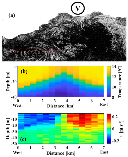
Figure 7.
(a) Subset of a Sentinel-1A SAR-C image acquired on 26 October 2021 at 05:43 UTC. (b) Measured temperature (colorbar legend: temperature range) and (c) velocity (colorbar legend: horizontal velocity range) along the measurement points (red dots) in (a). Blue: southward currents; red: northward currents. V: reference point marked in Figure 1.
The simulated temperature and velocity for the same time as in the SAR image show a cyclonic eddy between two anticyclonic gyres (Figure 8a) with a circular cold area at the center of the eddy surrounded by cold/warm filaments. The spatial variability of the mixed layer depth adjacent to the cyclonic and anticyclonic circulations is presented in Figure 8b. Here, the mixed layer is defined as the layer that has a temperature gradient <0.1 °C m−1 and where the total temperature difference from the water surface to the MLD (Mixed Layer Depth) is <2 °C [72]. A shallower mixed layer due to upwelling at the center of the cyclonic eddy was formed as opposed to a deeper mixed layer due to downwelling at the center of the anticyclonic gyres. The vertical motion associated with eddies and gyres creates a 15–20 m MLD difference between the cyclonic and anticyclonic eddies. Similar MLD differences between the center of the cyclonic eddy and its edges were observed in the field.
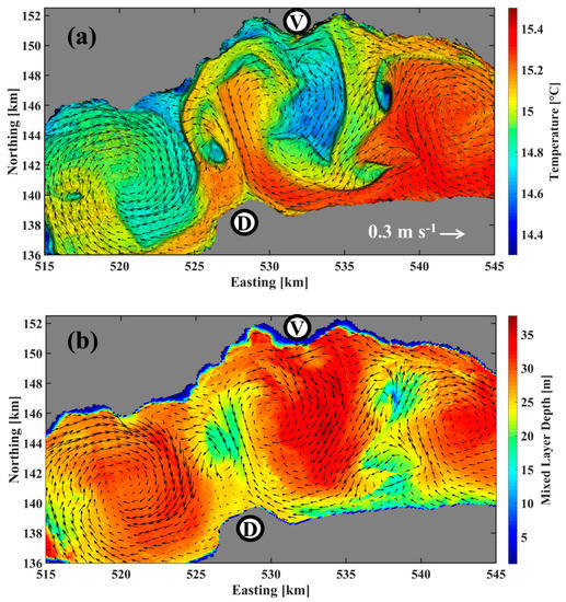
Figure 8.
(a) Simulated temperature (colors; colorbar legend: temperature range) and current (arrows; reference arrow in legend) at 0.3 m depth. (b) Simulated Mixed Layer Depth (colorbar legend: depth range) from a high-resolution, 3D numerical simulation for 26 October 2021 at 06:00 UTC. V and D are the reference points marked in Figure 1.
SAR imagery has rarely been used to detect eddies in lake studies. Previous studies that used SAR imagery to identify eddies focused primarily on their statistics [17,18,19,20,21]. McKinney et al. [49] reported small-scale cold cyclonic eddies in Lake Superior using data from Advanced Very High-Resolution Radiometers (AVHRR) and SAR. These authors studied statistics regarding the diameter, location, rotational sign, and temporal occurrence of small eddies in nearshore areas. Their AVHRR data indicated that cyclonic eddies are accompanied by cold cores, whereas anticyclonic eddies are accompanied by warm cores. A small eddy with a cold core was also observed during our campaign in October 2021. However, the present study is the first one in a lake that links surface observations of mesoscale gyres and submesoscale eddies to their vertical structure in the water column below.
4. Discussion
The above analysis of SAR images, 3D numerical modeling results and field observations shows that, under calm wind conditions, the patterns observed in SAR images are predominantly produced by biogenic slicks and surface roughness changes related to pelagic upwelling. Below, the contribution to the NRCS by different physical and biological processes, such as (i) an increase in air–water stability or an increase in the viscosity of surface water in the active phase of pelagic upwelling, (ii) a decrease of water elevation due to the baroclinic pressure gradient induced by pelagic upwelling, and (iii) rapid algae growth following nutrient uptake due to the pelagic upwelling, will be discussed.
Similar to coastal upwelling, upwelling in the center of a cyclonic gyre can be divided into two phases: (i) the active phase, during which upwelled water can reach the surface and remain there for a few days depending on the interaction between the gyre velocity field and the thermocline, and (ii) the relaxation phase, during which the upwelling at the center cannot reach the surface and the gyre velocity begins to decline. In the second phase, submesoscale filaments, squirts and whirls can be formed either through filamentogenesis/frontogenesis [35,50,73] or by baroclinic instability [73,74] in adjacent pelagic upwelling. As an example, the simulated surface water temperature and SAR image on 21 July 2018 (Figure 3) show several filamentary patterns of temperature/slicks inside the cyclonic gyre at the center of the lake. The vertical profiles of temperature at the center of the gyre velocity field (Figure 9b) indicate that the pelagic upwelling is in the relaxation phase. In the mixed layer, cold filaments appear as well-mixed columns of colder water. The cold-water mass patches in the mixed layer result from filamentogenesis/frontogenesis, which involves a rapid sharpening of the horizontal temperature/density gradient that is caused by large-scale confluent deformational flow [50,74]. At the location of the cold filament, a two-cell secondary circulation with stronger surface convergence and downwelling at its center is formed and restores the geostrophic and hydrostatic balances [35]. As a result, such convergence zones can accumulate surfactants and pollution at the center of cold filaments.
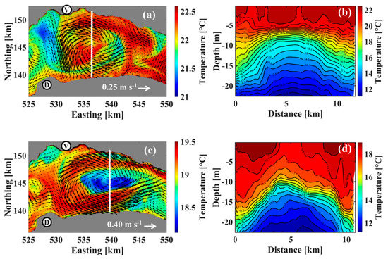
Figure 9.
(a) Simulated temperature and current (0.3 m depth), and (b) simulated temperature profile along the white transect in (a) from the high-resolution, 3D numerical simulation for 21 July 2018 at 17:00 UTC. (c) Simulated temperature and current (0.3 m depth), and (d) simulated temperature profile along the white transect in (c) from the 3D numerical simulation for 21 September 2019 at 17:00 UTC. In (a,c), colors: temperature; colorbar legend: temperature range and arrows: currents; reference arrow in legend. V and D: reference points marked in Figure 1. In (b,d), zero on the x-axis is at the southern end of the transect; colorbar legend: temperature range.
Figure 10b shows the variability of NRCS () values along the transect in Figure 10a. Two filamentary slicks, F1 and F3, with larger widths (~300–400 m), exhibit a greater drop (~6–8 dB) in NRCS values than the narrower slicks. Numerical results predict the presence of two cold filaments near F1 and F3. The water in the cold filaments is 0.5–1 °C cooler than the ambient water. Based on a combination of field data and numerical simulations, Hamze-Ziabari et al. [50] observed a similar filamentary pattern in a SAR image with the same spatial scale, which was accompanied by a temperature gradient of 1–2 °C. Theory predicts that a combination of high ageostrophic strain rate and buoyancy gradient caused by pelagic/coastal upwelling can create filamentary patches of cold water in the mixed layer [74]. Figure 3c, for example, shows that a high ageostrophic strain rate, which is three to five times greater than the Coriolis frequency, is present in the location of a cold filament. Such conditions are favorable for filamentogenesis/frontogenesis. It is well known that surfactants are often trapped and accumulated at the water surface inside such filamentary structures due to intense upwelling/downwelling cells induced by ageostrophic secondary circulation, and thus they can document the presence of filaments in SAR images [35].
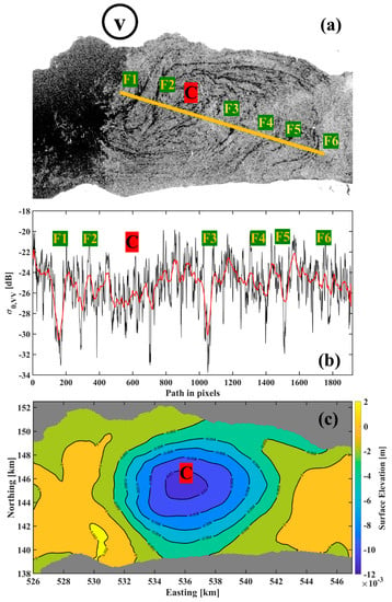
Figure 10.
(a) Subset of a Sentinel-1B SAR-C image acquired on 21 July 2018 at 17:31 UTC. Filaments are marked by F along the orange transect; C: center of the gyre. (b) Variability of the raw NRCS data () and the moving average (red line) along the orange transect shown in (a). (c) Simulated water surface elevation (given as the offset from the average water level) for 21 July 2018 at 18:00 UTC for the area shown in (a). Colorbar legend: range of surface elevation. V: reference point marked in Figure 1.
On the other hand, the SAR imagery of 20 and 21 September 2019 (Figure 5) shows patterns quite different from those typically observed in a cyclonic eddy/gyre. Figure 9d illustrates the simulated temperature profiles at the center of the cyclonic gyre, where dark elliptical patterns are present. The temperature profiles suggest that the pelagic upwelling caused by the cyclonic gyre is in the active phase and that the thermocline water reached the surface. Consequently, the temperature at the center of the cyclonic gyre was 1–1.5 °C lower than the ambient water, as confirmed by field observations. The variability of NRCS values along two transects A–A’ and B–B’, located in the dark elliptical patterns, is plotted in Figure 5c and d, respectively. Along A–A’, the drop in NRCS values in smooth areas can reach 10–15 dB compared to rough areas. However, for B–B’, which corresponds to the SAR image taken a day later at nearly the same time, the NRCS values only drop 5–10 dB at the center of the cyclonic gyre. The wind speed measured at two field meteorological stations, LéXPLORE and Buchillon Mast (see Figure 1 for locations), is plotted in Figure 11. The wind speed was recorded every 10 min at the LéXPLORE station, whereas it was measured hourly at the Buchillon station. According to both sets of field data, the wind speed was low during both events. Furthermore, the NRCS values in the rough area are comparable.
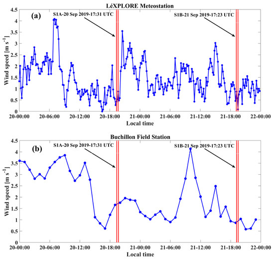
Figure 11.
Wind speed measured at the (a) LéXPLORE and (b) Buchillon stations during 20–21 September 2019. For locations, see Figure 1. Red parallel lines: times when SAR satellite images were taken.
Changes in SST affect NRCS by altering the stability of the atmospheric marine boundary layer and the viscosity of surface waters [26,27,28,29,30]. An increase in surface boundary layer stability over the upwelling zone leads to a reduction of wind stress by reducing the drag coefficient. An increase in the viscous properties of the surface layer can have an additional effect on the damping and initiation of Bragg waves. For example, according to [23,24], a 0.26-0.76 dB/°C ratio describes the NRCS to SST relationship over the coastal upwelling zone. However, the reduction of NRCS values due to an increase in air-water stability over the upwelling zone is typically smaller than 3 dB. The numerical results and field observations show that the drop in temperature at the center of the cyclonic gyre reaches 1–1.5 °C, which can theoretically result in a maximum NRCS reduction of ~0.26–1.14 dB [23,24]. Clearly, such processes cannot be the only mechanisms responsible for the 5–15 dB reduction of NRCS values in the center of the cyclonic gyre observed on 20 and 21 September.
The effect of SST on the NRCS is relatively small compared to that due to surfactants [23,30], which can be up to 5–10 dB [40]. Surfactants originate from biological activities and terrestrial sources introduced by catchments around the lake [52]. Due to the divergence of the flow field at the center of a cyclonic gyre/eddy, an accumulation of terrestrial source material therein seems unlikely. This suggests that the source of surfactants at the center of the lake is probably autochthonous [52]. A field study in Lake Tanganyika revealed that nutrient concentrations and phytoplankton chlorophyll levels increased in the pelagic upwelling zone [75]. As nutrients increase in the upwelling area, primary production increases [76], which can explain the increase in phytoplankton chlorophyll concentrations in the mixed layer and the presence of biogenic surfactants on the water surface. A negative correlation between lake surface water temperature and chlorophyll-a dynamics during summer and autumn was reported in Lake Geneva [77]. In summer and autumn, the photic surface layer is nutrient-limited, and the pelagic upwelling can bring nutrient-rich water from the deeper layer to the photic zone, which enhances the photosynthetic growth of phytoplankton, thus increasing chlorophyll-a concentrations. In the active phase of upwelling, the deep maximum chlorophyll can be transported from the photic zone and mixed with the surface water. It was previously shown that the reduction of NRCS values is highly correlated to chlorophyll-a concentration and that an increase of 1 mg m−3 corresponds to a 5–dB reduction of NRCS values [28].
The NRCS reduction of 10–15 dB on 20 September (see Figure 5c) at the center of the cyclonic gyre can be clearly related to the biological activity in the upwelling zone. One hypothesis is that rapid algae growth occurred on 20 September following nutrient uptake due to the pelagic upwelling. However, the concentration of chlorophyll-a may decrease due to nutrient consumption caused by the bloom that occurred the day before. Since the maximum chlorophyll-a concentration is in the deep photic zone during September in Lake Geneva, more intense upwelling on 20 September compared to 21 September could bring more deep phytoplankton to the surface and pseudo algae blooms could occur at the near-surface. However, there is no clear evidence about the response time of biological activity to either the active or relaxation phases of upwelling at the center of the cyclonic gyre; further research is needed.
Baroclinic pressure gradient induced by pelagic upwelling can lead to a decrease in water surface elevation at the center of cyclonic eddies/gyres [11]. Depending on the amount of upwelling at deeper layers, the reduction of surface elevation can be spatially and temporary variable. For example, the simulated water elevations at the center of the cyclonic gyre for 20 September 2019 reached -0.020 m and -0.016 m on 21 September 2019 (Figure 12a and b, respectively). The MLDs indicate that on 20 September, compared with the ambient water, the pelagic upwelling at the center of the gyre was almost 3 m higher than on 21 September (Figure 12). Previous studies used SAR imagery to retrieve the change of water elevation in lakes/reservoirs and significant wave height based on NRCS values extracted from SAR imagery (e.g., [78,79]). Therefore, it can be expected that the variation of water elevation induced by eddies/gyres also impacts the NRCS values. For example, the NRCS values marginally reduce by 1–2 dB at the center of the gyre observed in the SAR image taken on 21 July 2018 (Figure 10b). According to Figure 10c, the simulated water elevation is −1 cm and the water elevation difference between the center and the ambient waters is almost 0.8–1 cm. On 20 and 21 September 2019, the simulated water elevation differences between the center of the gyre and nearshore waters almost reach 2 cm and 1.5 cm, respectively. Such water elevation differences can be another reason for the differences between the observed NRCS values at the center of the gyre on 20 and 21 September.
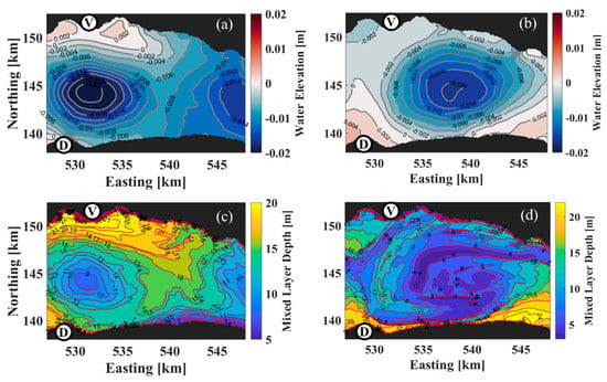
Figure 12.
Simulated surface water elevation for (a) 20 September 2019 at 18:00 UTC and (b) 21 September 2019 at 18:00 UTC. Simulated MLD for (c) 20 September 2019 at 18:00 UTC and (d) 21 September 2019 at 18:00 UTC. Colorbars show ranges. V and D: reference points marked in Figure 1.
SAR imagery provides a 2D high-resolution picture of surface roughness over large lakes from which new insights into mesoscale/submesoscale processes can be obtained. Existing databases on mesoscale/submesoscale processes in large lakes are limited to a few measurement points, and thus cannot realistically capture the complex lake hydrodynamics and related biological processes. For example, unlike the field observations and numerical simulations, the SAR image taken on 26 October shows several filamentary slicks around the center of the cyclonic eddy. Although model results, field observations and SAR imagery are all consistent, only the SAR imagery reveals submesoscale features with widths less than 100 m inside the submesoscale cyclonic eddy. These features are evident in SAR images because of the very high spatial resolution (a few meters) compared with the coarser resolution of the numerical simulation (113 m) and field observations (~500 m or more). The formation of such submesoscale filamentary patterns inside the submesoscale eddy observed in the SAR image can be due to very focused convergence zones and horizontal strain zones (Figure 13) caused by the interaction of the submesoscale eddy and the two mesoscale gyres. These submesoscale patterns in the SAR imagery can potentially be indicative of isolated water masses and hotspots for aggregation of populations of organisms and pollution.
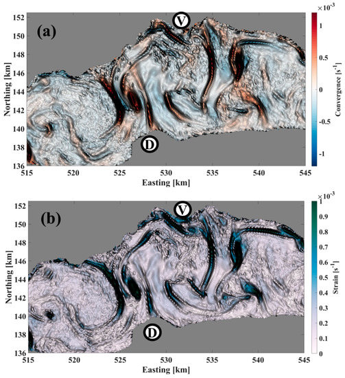
Figure 13.
(a) Simulated surface convergence, given by , and (b) horizontal strain rate for 26 October 2021 at 06:00 UTC. V and D are reference points marked in Figure 1.
5. Conclusions
A unique combination of SAR remote sensing imagery, high-resolution numerical modeling and field observations was used to investigate submesoscale and mesoscale processes associated with eddies/gyres in Lake Geneva. The present study is the first one in a lake that links surface observations of mesoscale gyres and submesoscale eddies to their vertical structure in the water column below. Compared to the ocean, the gradient of surface currents induced by the interaction of waves and currents is not sufficiently large in Lake Geneva to result in a variation of surface roughness that can be detected by SAR imagery. Instead, in Lake Geneva, the patterns associated with gyres/eddies observed in the SAR images between 2018 and 2021 are mainly due to the presence of biogenic slicks in the convergence zones of the flow velocity field. In this study, we showed that in a cyclonic gyre/eddy, pelagic upwelling can occur at its center. The results indicate that the cyclonic gyre characterized by this upwelling is generally more energetic than a gyre revealed by biogenic filamentary slicks and temperature. The pelagic upwelling in the center of the gyre manifested by biogenic slicks in the SAR images was already in the relaxation phase and the upwelled water could not reach the water surface. However, numerical results and field observations indicated that the pelagic upwelling at the center of the cyclonic gyre had an earlier active phase when upwelled water could reach the water surface. In the active phase of upwelling, a ‘dark’ elliptical region appeared in the SAR image in the area where upwelled water reached the surface.
The NRCS values dropped by 5–15 dB in the smooth upwelling areas compared with the surrounding rough areas. The significant reduction of NRCS values in the center of the cyclonic gyre can potentially be due to physical and biological processes such as (i) an increase in water–air stability or increase in viscosity of surface water in the active phase of pelagic upwelling, (ii) a decrease in water elevation due to a baroclinic pressure gradient induced by pelagic upwelling, and (iii) a rapid algae growth following nutrient uptake due to the pelagic upwelling or vertical transport of deep phytoplankton and maximum chlorophyll concentrations in September due to intense upwelling. In previous studies, SAR imagery has been widely used to analyze the statistics of submesoscale or mesoscale eddies in seas/oceans. In those studies, the so-called ‘black’ or ‘white’ eddies were used to investigate seasonal variations of submesoscale/mesoscale eddies. However, the present study showed that a cyclonic eddy can also be manifested by pelagic upwelling. This pattern was overlooked in previous studies and can help improve the statistics of eddies retrieved from SAR imagery.
Mesoscale/submesoscale patterns in field observations, 3D numerical modeling, and SAR images were shown to be closely correlated and complementary. SAR imagery can give valuable new information about physical and biological processes induced by mesoscale or submesoscale processes in Lake Geneva. Since SAR images are taken regularly at short time intervals, they allow for determination of the frequency and thus the significance of these large-scale patterns in the long-term ecological development of the lake system. In particular, SAR images can indicate potential biochemical hotspots related to pelagic upwelling and submesoscale features such as filaments in large lakes. High-resolution SAR imagery in combination with realistic validated numerical models and multi-sensor imagery can be used to better design field campaigns that seek to unravel the complex interactions of biological–chemical–physical large-scale processes associated with basin-, meso- or submesoscale currents in large lakes subject to the Coriolis force. Understanding these processes is required for developing effective lake management concepts.
Author Contributions
Conceptualization, S.M.H.-Z., U.L., M.F. and D.A.B.; methodology, S.M.H.-Z.; software, S.M.H.-Z. and M.F.; validation, S.M.H.-Z. and M.F.; formal analysis, S.M.H.-Z.; investigation, S.M.H.-Z., U.L., M.F. and D.A.B.; resources, D.A.B. and U.L.; data curation, S.M.H.-Z.; writing—original draft preparation, S.M.H.-Z.; writing—review and editing, U.L., D.A.B. and M.F.; visualization, S.M.H.-Z. and M.F.; supervision, D.A.B.; project administration, D.A.B.; funding acquisition, D.A.B. All authors have read and agreed to the published version of the manuscript.
Funding
This research was funded by the Swiss National Science Foundation (SNSF Grant 178866).
Data Availability Statement
Not applicable.
Acknowledgments
The spatiotemporal meteorological data were provided by the Federal Office of Meteorology and Climatology in Switzerland (MeteoSwiss). We also extend our appreciation to the Commission Internationale pour la Protection des Eaux du Léman (CIPEL) for in situ temperature measurements. Water temperature profiles were collected at the CIPEL SHL2 station for 2018–2019 by the Eco-Informatics ORE INRA Team at the French National Institute for Agricultural Research (SOERE OLA-IS, INRA Thonon-les-Bains, France). We thank the reviewers for their constructive comments and suggestions.
Conflicts of Interest
The authors declare no conflict of interest.
Appendix A
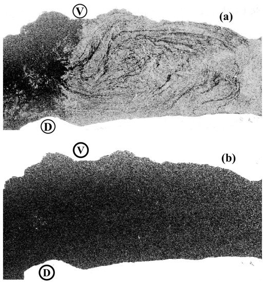
Figure A1.
Subset of a Sentinel-1B SAR-C image acquired on 21 July 2018 at 17:31 UTC (a) co-polarization (VV), and (b) cross-polarization (VH). V and D: reference points marked in Figure 1.
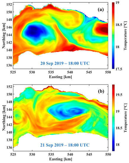
Figure A2.
Simulated temperature (0.3 m depth; colorbar legend: temperature range) from a high-resolution, 3D numerical simulation of Lake Geneva for (a) 20 September 2019 at 18:00 UTC, and (b) 21 September 2019 at 18:00 UTC. Easting and northing coordinates follow the Swiss CH1903 system.
References
- Ji, Z.G.; Jin, K.R. Gyres and seiches in a large and shallow lake. J. Great Lakes Res. 2006, 32, 764–775. [Google Scholar] [CrossRef]
- Ishikawa, K.; Kumagai, M.; Vincent, W.F.; Tsujimura, S.; Nakahara, H. Transport and accumulation of bloom-forming cyanobacteria in a large, mid-latitude lake: The gyre-Microcystis hypothesis. Limnology 2002, 3, 87–96. [Google Scholar] [CrossRef]
- Csanady, G.T. Wind-induced barotropic motions in long lakes. J. Phys. Oceanogr. 1973, 3, 429–438. [Google Scholar] [CrossRef]
- Csanady, G.T. Hydrodynamics of large lakes. Annu. Rev. Fluid Mech. 1975, 7, 357–386. [Google Scholar] [CrossRef]
- Rao, D.B.; Murty, T.S. Calculation of the steady state wind-driven circulations in Lake Ontario. Arch. Meteorol. Geophys. Bioclimatol. A 1970, 19, 195–210. [Google Scholar] [CrossRef]
- Zhan, S.; Beck, R.A.; Hinkel, K.M.; Liu, H.; Jones, B.M. Spatio-temporal analysis of gyres in oriented lakes on the Arctic Coastal Plain of northern Alaska based on remotely sensed images. Remote Sens. 2014, 6, 9170–9193. [Google Scholar] [CrossRef]
- Beletsky, D.; Saylor, J.H.; Schwab, D.J. Mean circulation in the Great Lakes. J. Great Lakes Res. 1999, 25, 78–93. [Google Scholar] [CrossRef]
- Beletsky, D.; Hawley, N.; Rao, Y.R. Modeling summer circulation and thermal structure of Lake Erie. J. Geophys. Res. Ocean. 2013, 118, 6238–6252. [Google Scholar] [CrossRef]
- Hui, Y.; Farnham, D.J.; Atkinson, J.F.; Zhu, Z.; Feng, Y. Circulation in Lake Ontario: Numerical and physical model analysis. J. Hydraul. Eng. 2021, 147, 05021004. [Google Scholar] [CrossRef]
- Faghmous, J.H.; Frenger, I.; Yao, Y.; Warmka, R.; Lindell, A.; Kumar, V. A daily global mesoscale ocean eddy dataset from satellite altimetry. Sci. Data 2015, 2, 150028. [Google Scholar] [CrossRef]
- Chelton, D.B.; Schlax, M.G.; Samelson, R.M. Global observations of nonlinear mesoscale eddies. Prog. Oceanogr. 2011, 91, 167–216. [Google Scholar] [CrossRef]
- Troitskaya, E.; Blinov, V.; Ivanov, V.; Zhdanov, A.; Gnatovsky, R.; Sutyrina, E.; Shimaraev, M. Cyclonic circulation and upwelling in Lake Baikal. Aquat. Sci. 2015, 77, 171–182. [Google Scholar] [CrossRef]
- Beletsky, D.; Hawley, N.; Rao, Y.R.; Vanderploeg, H.A.; Beletsky, R.; Schwab, D.J.; Ruberg, S.A. Summer thermal structure and anticyclonic circulation of Lake Erie. Geophys. Res. Lett. 2012, 39, L06605. [Google Scholar] [CrossRef]
- Cheng, Y.H.; Ho, C.R.; Zheng, Q.; Kuo, N.J. Statistical characteristics of mesoscale eddies in the North Pacific derived from satellite altimetry. Remote Sens. 2014, 6, 5164–5183. [Google Scholar] [CrossRef]
- Shu, S.; Yang, J.; Yang, C.; Hu, H.; Jing, W.; Hu, Y.; Li, Y. Performance analysis of ocean eddy detection and identification by L-Band compact polarimetric synthetic aperture radar. Remote Sens. 2021, 13, 4905. [Google Scholar] [CrossRef]
- Shomina, O.; Danilicheva, O.; Tarasova, T.; Kapustin, I. Manifestation of spiral structures under the action of upper ocean currents. Remote Sens. 2022, 14, 1871. [Google Scholar] [CrossRef]
- Karimova, S. Spiral eddies in the Baltic, Black and Caspian seas as seen by satellite radar data. Adv. Space Res. 2012, 50, 1107–1124. [Google Scholar] [CrossRef]
- Fu, L.L.; Ferrari, R. Observing oceanic submesoscale processes from space. Eos Trans. Am. Geophys. Union 2008, 89, 488. [Google Scholar] [CrossRef]
- Topouzelis, K.; Kitsiou, D. Detection and classification of mesoscale atmospheric phenomena above sea in SAR imagery. Remote Sens. Environ. 2015, 160, 263–272. [Google Scholar] [CrossRef]
- Yamaguchi, S.; Kawamura, H. SAR-imaged spiral eddies in Mutsu Bay and their dynamic and kinematic models. J Oceanogr. 2009, 65, 525–539. [Google Scholar] [CrossRef]
- Xu, G.; Yang, J.; Dong, C.; Chen, D.; Wang, J. Statistical study of submesoscale eddies identified from synthetic aperture radar images in the Luzon Strait and adjacent seas. Int. J. Remote Sens. 2015, 36, 4621–4631. [Google Scholar] [CrossRef]
- Gurova, E.; Lehmann, A.; Ivanov, A. Upwelling dynamics in the Baltic Sea studied by a combined SAR/infrared satellite data and circulation model analysis. Oceanologia 2013, 55, 687–707. [Google Scholar] [CrossRef]
- Clemente-Colón, P.; Yan, X.H. Observations of east coast upwelling conditions in synthetic aperture radar imagery. IEEE Trans. Geosci Remote Sens. 1999, 37, 2239–2248. [Google Scholar] [CrossRef]
- Clemente-Colón, P. Evolution of upwelling-associated biological features in the Middle Atlantic Bight as captured by SAR, SST, and ocean colour sensors. In IGARSS 2001. Scanning the Present and Resolving the Future, Proceedings of the IEEE 2001 International Geoscience and Remote Sensing Symposium (Cat. No.01CH37217), Sydney, Australia, 9–13 July 2001; IEEE: Manhattan, NY, USA, 2001; Volume 6, pp. 2616–2618. [Google Scholar]
- Gurova, E.S.; Ivanov, A.Y. Appearance of sea surface signatures and current features in the South-East Baltic Sea on the MODIS and SAR images. Issled. Zemli Kosm. 2011, 4, 41–54. [Google Scholar]
- Friehe, C.A.; Shaw, W.J.; Rogers, D.P.; Davidson, K.L.; Large, W.G.; Stage, S.A.; Crescenti, G.H.; Khalsa, S.J.S.; Greenhut, G.K.; Li, F. Air-sea fluxes and surface layer turbulence around a sea surface temperature front. J. Geophys. Res. 1991, 96, 8593–8609. [Google Scholar] [CrossRef]
- Zheng, Q.; Yan, X.H.; Huang, N.E.; Klemas, V.; Pan, J. The effects of water temperature on radar scattering from the water surface: An x-band laboratory study. Glob. Atmos. Ocean. Syst. 1997, 5, 273–294. [Google Scholar]
- Lin, I.I.; Wen, L.S.; Liu, K.K.; Tsai, W.T.; Liu, A.K. Evidence and quantification of the correlation between radar backscatter and ocean colour supported by simultaneously acquired in situ sea truth. Geophys. Res. Lett. 2002, 29, 102-1–102-4. [Google Scholar] [CrossRef]
- Keller, W.C.; Wismann, V.; Alpers, W. Tower-based measurements of the ocean C band radar backscattering cross section. J. Geophys. Res. Ocean. 1989, 94, 924–930. [Google Scholar] [CrossRef]
- Alpers, W.; Zeng, K. On radar signatures of upwelling. J. Geod. Geoinf. Sci. 2021, 4, 17. [Google Scholar]
- Alpers, W.; Huhnerfuss, H. The damping of ocean waves by surface films: A new look at an old problem. J. Geophys. Res. 1989, 94, 6251–6265. [Google Scholar] [CrossRef]
- Marmorino, G.O.; Holt, B.; Molemaker, M.J.; DiGiacomo, P.M.; Sletten, M.A. Airborne synthetic aperture radar observations of “spiral eddy” slick patterns in the Southern California Bight. J. Geophys. Res. Ocean. 2010, 115, C05010. [Google Scholar] [CrossRef]
- Cooper, A.L.; Shen, C.Y.; Marmorino, G.O.; Evans, T. Simulated radar imagery of an ocean “spiral eddy”. Trans. Geosci. Remote Sens. 2005, 43, 2325–2331. [Google Scholar] [CrossRef]
- Johannessen, J.A.; Kudryavtsev, V.; Akimov, D.; Eldevik, T.; Winther, N.; Chapron, B. On radar imaging of current features: 2. Mesoscale eddy and current front detection. J. Geophys. Res. 2005, 110, C07017. [Google Scholar] [CrossRef]
- McWilliams, J.C.; Colas, F.; Molemaker, M.J. Cold filamentary intensification and oceanic surface convergence lines. Geophys. Res. Lett. 2009, 36, L18602. [Google Scholar] [CrossRef]
- DiGiacomo, P.M.; Holt, B. Satellite observations of small coastal ocean eddies in the Southern California Bight. J. Geophys. Res. 2001, 106, 22521–22543. [Google Scholar] [CrossRef]
- Ji, Y.; Xu, G.; Dong, C.; Yang, J.; Xia, C. Submesoscale eddies in the East China Sea detected from SAR images. Acta Oceanol. Sin. 2021, 40, 18–26. [Google Scholar] [CrossRef]
- Johannessen, J.A.; Shuchman, R.A.; Digranes, G.; Lyzenga, D.R.; Wackerman, C.; Johannessen, O.M.; Vachon, P.W. Coastal ocean fronts and eddies imaged with ERS 1 synthetic aperture radar. J. Geophys. Res. Ocean. 1996, 101, 6651–6667. [Google Scholar] [CrossRef]
- Dokken, S.T.; Wahl, T. Observations of Spiral Eddies along the Norwegian Coast. In ERS SAR Images; Rep. 96/01463; Norwegian Defence Research Establishment: Kjeller, Norway, 1996. [Google Scholar]
- Alpers, W.; Bignami, F. Small-Scale and Sub-Mesoscale Phenomena Associated with Upwelling Studied by SAR. In Proceedings of the IGARSS 2020—2020 IEEE International Geoscience and Remote Sensing Symposium, Waikoloa, HI, USA, 26 September–2 October 2020; pp. 3537–3540. [Google Scholar]
- Ẑutić, V.; Ćosović, B.; Marčenko, E.; Bihari, N.; Kršinić, F. Surfactant production by marine phytoplankton. Mar. Chem. 1981, 10, 505–520. [Google Scholar] [CrossRef]
- Kurata, N.; Vella, K.; Hamilton, B.; Shivji, M.; Soloviev, A.; Matt, S.; Tartar, A.; Perrie, W. Surfactant-associated bacteria in the near-surface layer of the ocean. Sci. Rep. 2016, 6, srep19123. [Google Scholar] [CrossRef]
- Kujawinski, E.B.; Farrington, J.W.; Moffett, J.W. Evidence for grazing-mediated production of dissolved surface-active material by marine protists. Mar. Chem. 2002, 77, 133–142. [Google Scholar] [CrossRef]
- Hunter, K.A.; Liss, P.S. Organic Sea Surface Films. In Marine Organic Chemistry; Duursma, E.K., Dawson, R., Eds.; Elsevier: Amsterdam, The Netherlands, 1981; Volume 31, pp. 259–298. ISBN 0422-9894. [Google Scholar]
- Tsai, W.; Liu, K.-K. An assessment of the effect of sea surface surfactant on global atmosphere-ocean CO2 flux. J. Geophys. Res. Ocean. 2003, 108, 3127. [Google Scholar] [CrossRef]
- De Santi, F.; Luciani, G.; Bresciani, M.; Giardino, C.; Lovergine, F.P.; Pasquariello, G.; Vaiciute, D.; De Carolis, G. Synergistic use of synthetic aperture radar and optical imagery to monitor surface accumulation of cyanobacteria in the Curonian Lagoon. J. Mar. Sci. Eng. 2019, 7, 461. [Google Scholar] [CrossRef]
- Friedman, K.S.; Li, X.; Pichel, W.G.; Clemente-Colon, P.; Walker, N.; Veenstra, T. Eddy Detection Using RADARSAT-1 Synthetic Aperture Radar. In Proceedings of the IGARSS 2004, 2004 IEEE International Geoscience and Remote Sensing Symposium, Anchorage, AK, USA, 20–24 September 2004; Volume 7, pp. 4707–4710. [Google Scholar]
- Ivanov, A.Y.; Ginzburg, A.I. Oceanic eddies in synthetic aperture radar images. J. Earth Syst. Sci. 2002, 111, 281–295. [Google Scholar] [CrossRef]
- McKinney, P.; Holt, B.; Matsumoto, K. Small eddies observed in Lake Superior using SAR and sea surface temperature imagery. J. Great Lakes Res. 2012, 38, 786–797. [Google Scholar] [CrossRef]
- Hamze-Ziabari, S.M.; Razmi, A.M.; Lemmin, U.; Barry, D.A. Detecting submesoscale cold filaments in a basin-scale gyre in large, deep Lake Geneva (Switzerland/France). Geophys. Res. Lett. 2022, 49, e2021GL096185. [Google Scholar] [CrossRef]
- Hamze-Ziabari, S.M.; Lemmin, U.; Soulignac, F.; Foroughan, M.; Barry, D.A. Basin-scale gyres and mesoscale eddies in large lakes: A novel procedure for their detection and characterization, assessed in Lake Geneva. Geosci. Model. Dev. 2022, 1–33, submitted. [Google Scholar]
- Foroughan, M.; Lemmin, U.; Barry, D.A. Effects of natural surfactants on the spatial variability of surface water temperature under intermittent light winds on Lake Geneva. J. Limnol. 2022, 81, 2048. [Google Scholar] [CrossRef]
- Lemmin, U. Insights into the dynamics of the deep hypolimnion of Lake Geneva as revealed by long-term temperature, oxygen, and current measurements. Limnol. Oceanogr. 2020, 65, 2092–2107. [Google Scholar] [CrossRef]
- Gao, Y.; Guan, C.; Sun, J.; Xie, L. A wind speed retrieval model for Sentinel-1A EW mode cross-polarization images. Remote Sens. 2019, 11, 153. [Google Scholar] [CrossRef]
- Fang, H.; Xie, T.; Perrie, W.; Zhang, G.; Yang, J.; He, Y. Comparison of C-band quad-polarization synthetic aperture radar wind retrieval models. Remote Sens. 2018, 10, 1448. [Google Scholar] [CrossRef]
- Filipponi, F. Sentinel-1 GRD Preprocessing Workflow. Proceedings 2019, 18, 11. [Google Scholar]
- Marshall, J.; Adcroft, A.; Hill, C.; Perelman, L.; Heisey, C. A finite-volume, incompressible Navier Stokes model for studies of the ocean on parallel computers. J. Geophys. Res. Ocean. 1997, 102, 5753–5766. [Google Scholar] [CrossRef]
- Cimatoribus, A.A.; Lemmin, U.; Bouffard, D.; Barry, D.A. Nonlinear dynamics of the nearshore boundary layer of a large lake (Lake Geneva). J. Geophys. Res. Ocean. 2018, 123, 1016–1031. [Google Scholar] [CrossRef]
- Cimatoribus, A.A.; Lemmin, U.; Barry, D.A. Tracking Lagrangian transport in Lake Geneva: A 3D numerical modeling investigation. Limnol. Oceanogr. 2019, 64, 1252–1269. [Google Scholar] [CrossRef]
- Reiss, R.S.; Lemmin, U.; Cimatoribus, A.A.; Barry, D.A. Wintertime coastal upwelling in Lake Geneva: An efficient transport process for deepwater renewal in a large, deep lake. J. Geophys. Res. Ocean. 2020, 125, e2020JC016095. [Google Scholar] [CrossRef]
- Reiss, R.S.; Lemmin, U.; Barry, D.A. Wind-induced hypolimnetic upwelling between the multi-depth basins of Lake Geneva during winter: An overlooked deepwater renewal mechanism? J. Geophys. Res. Ocean. 2022, 127, e2021JC018023. [Google Scholar] [CrossRef]
- Voudouri, A.; Avgoustoglou, E.; Kaufmann, P. Impacts of Observational Data Assimilation on Operational Forecasts. In Perspectives on Atmospheric Sciences; Karacostas, T., Bais, A., Nastos, P.T., Eds.; Springer International Publishing: Cham, Switzerland, 2017; pp. 143–149. [Google Scholar]
- CIPEL. Rapports Sur Les Études et Recherches Entreprises Dans Le Bassin Lémanique, Campagne 2018; Commission Internationale Pour la Protection des eaux du Léman (CIPEL): Nyon, Switzerland, 2019. [Google Scholar]
- Jackson, C.R.; Apel, J.R. Synthetic Aperture Radar Marine User’s Manual; US Department of Commerce, National Oceanic and Atmospheric Administration: Washington, DC, USA, 2004; Available online: http://www.sarusersmanual.com (accessed on 13 September 2022).
- Elfouhaily, T.; Thompson, D.R.; Vandemark, D.; Chapron, B. A new bistatic model for electromagnetic scattering from perfectly conducting random surfaces. Waves Random Media 1999, 9, 281–294. [Google Scholar] [CrossRef]
- Elfouhaily, T.; Thompson, D.R.; Freund, D.E.; Vandemark, D.; Chapron, B. A new bistatic model for electromagnetic scattering from perfectly conducting random surfaces: Numerical evaluation and comparison with SPM. Waves Random Media 2001, 11, 33–43. [Google Scholar] [CrossRef]
- Tritton, D.J. Physical Fluid Dynamics; Springer Science & Business Media: Berlin/Heidelberg, Germany, 2012; ISBN 978-94-009-9992-3. [Google Scholar]
- Large, W.G.; Pond, S. Open ocean momentum flux measurements in moderate to strong winds. J. Phys. Oceanogr. 1981, 11, 324–336. [Google Scholar] [CrossRef]
- Fairall, C.W.; Bradley, E.F.; Hare, J.E.; Grachev, A.A.; Edson, J.B. Bulk parameterization of air–sea fluxes: Updates and verification for the COARE algorithm. J. Clim. 2003, 16, 571–591. [Google Scholar] [CrossRef]
- Grachev, A.A.; Bariteau, L.; Fairall, C.W.; Hare, J.E.; Helmig, D.; Hueber, J.; Lang, E.K. Turbulent fluxes and transfer of trace gases from ship-based measurements during TexAQS 2006. J. Geophys. Res. Atmos. 2011, 116, D13110. [Google Scholar] [CrossRef]
- Mahadevan, A. The impact of submesoscale physics on primary productivity of plankton. Ann. Rev. Mar. Sci. 2016, 8, 161–184. [Google Scholar] [CrossRef] [PubMed]
- Xu, W.; Collingsworth, P.D.; Minsker, B. Algorithmic characterization of lake stratification and deep chlorophyll layers from depth profiling water quality data. Water Resour. Res. 2019, 55, 3815–3834. [Google Scholar] [CrossRef]
- Gula, J.; Molemaker, M.J.; McWilliams, J.C. Submesoscale cold filaments in the Gulf Stream. J. Phys. Oceanogr. 2014, 44, 2617–2643. [Google Scholar] [CrossRef]
- McWilliams, J.; Molemaker, M. Baroclinic frontal arrest: A sequel to unstable frontogenesis. J. Phys. Oceanogr. 2011, 41, 601–619. [Google Scholar] [CrossRef]
- Corman, J.R.; McIntyre, P.B.; Kuboja, B.; Mbemba, W.; Fink, D.; Wheeler, C.W.; Gans, C.; Michel, E.; Flecker, A.S. Upwelling couples chemical and biological dynamics across the littoral and pelagic zones of Lake Tanganyika, East Africa. Limnol. Oceanogr. 2010, 55, 214–224. [Google Scholar] [CrossRef]
- Jane, S.F.; Hansen, G.J.; Kraemer, B.M.; Leavitt, P.R.; Mincer, J.L.; North, R.L.; Pilla, R.M.; Stetler, J.T.; Williamson, C.E.; Woolway, R.I.; et al. Widespread deoxygenation of temperate lakes. Nature 2021, 594, 66–70. [Google Scholar] [CrossRef] [PubMed]
- Bouffard, D.; Kiefer, I.; Wüest, A.; Wunderle, S.; Odermatt, D. Are surface temperature and chlorophyll in a large deep lake related? An analysis based on satellite observations in synergy with hydrodynamic modelling and in-situ data. Remote Sens. Environ. 2018, 209, 510–523. [Google Scholar] [CrossRef]
- Xue, S.; Geng, X.; Yan, X.H.; Xie, T.; Yu, Q. Significant wave height retrieval from Sentinel-1 SAR imagery by convolutional neural network. J. Oceanogr. 2020, 76, 465–477. [Google Scholar] [CrossRef]
- Xing, L.; Tang, X.; Wang, H.; Fan, W.; Wang, G. Monitoring monthly surface water dynamics of Dongting Lake using Sentinel-1 data at 10 m. PeerJ 2018, 6, e4992. [Google Scholar] [CrossRef]
Publisher’s Note: MDPI stays neutral with regard to jurisdictional claims in published maps and institutional affiliations. |
© 2022 by the authors. Licensee MDPI, Basel, Switzerland. This article is an open access article distributed under the terms and conditions of the Creative Commons Attribution (CC BY) license (https://creativecommons.org/licenses/by/4.0/).