Abstract
An ever-increasing global population and unabating technological growth have resulted in a relentless appetite for mineral resources, namely rare earth elements, fuel minerals and those utilised in electronics applications, with the price of such species continuing to climb. In contrast to more established large-scale and high-cost exploration methodologies, this work details the application of novel multi-rotor unmanned aerial vehicles equipped with miniaturised radiation detectors for the objective of undertaking resource exploration at lower costs, with greater autonomy and at considerably enhanced higher spatial resolutions; utilizing the ore material’s inherent low levels of characteristic radioactivity. As we demonstrate at the former Wooley Mine site in Arizona, USA, a legacy Cu/Fe prospect where the 600 by 275 m ore body (with a maximum deposit depth of 150 m), it is shown that such a fusion of commercially available low-altitude multi-rotor aerial technology combined with cutting-edge micro-electronics and detector materials is capable of accurately assessing the spatial distribution and associated radiogenic signatures of commercially valuable surface/near-surface ore bodies. This integrated system, deployed at an autonomously controlled consistent survey altitude and using constant grid transects/separations, is shown to be able to delineate the mineral-containing ore deposits on the site, the location(s) of former mine workings and other surface manifestations. Owing to its advantageous costs alongside its ease of operation and subsequent data-processing, through the adoption of this system, it is envisaged that less economically developed countries would now possess the means through which to evaluate and appropriately quantify their mineral wealth without the significant initial expenditure needed to equip themselves with otherwise prohibitively expensive technologies.
1. Introduction
Globally, there is a growing and insatiable appetite for consumer electronic devices and a commensurate demand for geological resources. The materials required to facilitate this growth include (bulk) metallic minerals (e.g., Fe, Al, Cu, Zn, Ti), specialist metals (e.g., Au, Ag, Pt, W), Rare Earth Elements (REEs) (e.g., Nd, La, Er, Yb, Y) [1], and fuel elements utilised as part of the nuclear fuel cycle (U, and more recently Th). These elements and minerals exist at varying concentrations within the earth’s crust, however, it is when these elements are encountered at markedly increased concentrations above their natural background abundance that it is referred to as an ore/mineral deposit or reserve [2] where, given the economic conditions, it may be viable to extract.
The methodologies employed to locate these essential and valuable surface/sub-surface ore bodies, such as those containing prized REEs, Pt Group metals and precious/semi-precious metals have remained largely unchanged in decades of geophysical surveying [3,4]. Such mainstays of large-area remote sensing are a combination of airborne techniques, including (i) gravimetry, (ii) magnetometry, and (iii) gamma-ray spectroscopy [5,6,7], conducted using helicopters or light-aircraft, which consequently introduces considerable detector–ground separation, and therefore lack the highest attainable spatial resolutions and sensitivities. For these techniques, ground-based equivalents also form part of the wider exploration portfolio to assess for economically valuable mineral assemblages.
These valuable bulk metallic, REE and precious metal mineral deposits are typically associated with low-activity radioactive minerals containing U and/or Th, and it is this inherent and easily detectable property (i.e., gamma-ray emission) that the aforementioned ore prospecting methods do not exploit. However, from the perspective of radiometric mineral prospecting, aerial mapping has been employed since the development of the first gamma-ray detectors, with procedures applied to all the radiometric data based on protocols described most recently in IAEA [8], and those of Grasty [9] and Minty [10]—with one of the most comprehensive airborne radiometric studies of regional geology, that of Beamish [5], covering south-west UK, albeit at a high altitude and with resultant poor spatial resolution.
While the aforementioned radiometric mapping works have occurred, it is notable that airborne radiometric surveying has not been utilised directly as a methodology in mineral prospecting. This is considered to be partly due to the relatively high operational and maintenance costs for manned aircraft (on the order of thousands of dollars per flight hour), but also as a result of the relatively coarse spatial resolution of the surveys (>50 m pixel on-ground resolution), which are appropriate for identifying large (regional-scale) features, but are too granular for resolving specific regions (typically on the meter-scale) of interest for subsequent “on-the-ground” exploration [11]. Hence, there exists a niche whereby recent innovations in both unmanned aerial vehicles (UAVs) and miniaturised (and lower cost) radiation detectors can provide a powerful solution, bridging the current capability and, more importantly, cost gap—the objective of this work. Such aerial systems cost substantially less to own and deploy that manned aircraft, but also offer potential gains in spatial resolution and gamma-sensitivity due to the lower altitudes and flight speeds that surveys can be conducted at. The trade-off is more limited flight times and payload weights (i.e., smaller detector volumes), meaning that only relatively small areas (currently up to ~1 km2) can be covered in a single flight. However, the wide applicability, alongside the novelty and innovation of this lightweight and user-friendly system (both hardware and associated software/data processing), is such that the technology represents a unique and cost-efficient survey tool—filling a significant current capability ‘void’.
The translational use of UAV radiation mapping drone technologies for mineral exploration was noted by Fortin et al. [12] and Muchiri and Kimathi [13], having since been demonstrated at legacy mines by Martin et al. [14], who surveyed the legacy workings and residual surface contamination manifestations at the near-surface (circa 5 m depth) South Terras uranium mine in Cornwall, UK. This work extends the preliminary work by Salek et al. [15], which successfully maps a considerably larger (80 × 40 m) ore body using a radiation-detector-equipped UAV, evolving the application of UAV combined with magnetometry systems for mineral exploration, as detailed in Malehmir et al. [16]. This work, hence, details the progression and contribution of low-altitude aerial robotics for resource exploration, combining UAV technology with enhanced radiation detection systems and intuitive post-processing algorithms through which to efficiently, and with minimal user input, locate ore resources. Such a process, including both data collection and subsequent post-processing, represents a method of enhanced efficiency through which surveys can be undertaken at lower-cost—therefore making the methodology accessible to those formerly lacking the means to deliver an accurate assessment of their subsurface mineral wealth. The objective of this work is, therefore, to evaluate (i) the modular aerial platform and sensory systems and (ii) the associated survey parameters, and assess their applicability as well as sensitivity for ore resource exploration using the materials intrinsic low-level radioactivity.
Following a description of the survey site in Arizona (USA) used in this exploratory study, the customized aerial platform employed, and the novel sequence of post-processing steps for the radiometric data derived, the methodology section of this manuscript subsequently details the laboratory-based analytical processes conducted to appropriately calibrate these aerially derived results. The following results section details the outcomes of the combined aerial mineralogical mapping and correlative ‘ground-truthing’ via in-lab techniques, before a comparison with the known subsurface geological conditions is made and a summary of the outcomes and impact of the work.
2. Materials and Methods
2.1. Survey Site
The site selected for characterisation as part of this proof-of-concept translational study was Wooley Mine (Longitude: −111.024580, Latitude: 33.045090), located in the mountains south east of Apache Junction in Arizona, USA (Figure S1, available within this manuscripts Supplementary Information). A documented copper prospect, it was established in 1895 and named after the district in which it was located—the mining claim situated on federal land managed by the U.S. Bureau of Land Management (BLM) Administrative Area. Suggestive from its title as a copper prospect, the most abundant element associated with the Wooley Mine was Cu and was extracted solely from near-surface vein deposits at a time where exploratory techniques and extraction processes were not as advanced as methods today. All the mining activities were underground, with one known vertical shaft and an intersecting horizontal adit shaft, with its entrance located downslope of the shaft head. While Cu was the most abundant element identified and extracted at Wooley Mine (with recorded abundance within ores of 1.6–7.2 wt%), the sites deposits also contained varying abundances of both Ag (0.19–0.9 wt%) and U (up to a maximum concentration of 0.04 wt%) [17,18]. The primary ores mined consisted of chrysocolla (hydrated copper phyllosilicate), malachite (copper carbonate hydroxide), and chalcocite (copper sulfide), with some chalcopyrite (copper-iron sulfide), and quartz (silicate), hematite (iron oxide), and limonite (hydrated iron oxide-hydroxide) waste rock. The ore body extended approximately 600 m long by 275 m wide, with a maximum depth of 150 m [19]. However, in contrast to other deposits within the region, the apparent abundance of valuable ore at Wooley Mine (at the time) was considered small—with production on the site ceasing 61 years later, in 1956.
Geologically, the region within which Wooley Mine resides is characterized by Middle Proterozoic Granites (rhyodacite) dating from 1.40–1.45 Gya [18]. It was derived from an evolved magmatic melt, rich in valuable elements (e.g., U, Th and the REEs) that are incompatible in more basic precursors. Such highly felsic lithologies and the immediately surrounding country rock are typical hosts of vein deposits on varying length-scale containing such valuable elements. Nearby rock also dates from the Pliocene epoch (5.33 to 2.58 mya).
2.2. Aerial Platform and Detection Systems
The aerial platform selected for this work was the DJI Matrice-100 (M100) multi-rotor UAV, fitted with a customized AARM radiation detection payload from Imitec Ltd. Under optimal wind conditions, the four-propeller drone was capable of attaining flight durations of approximately 20 min with the 1 kg integrated radiation detection and mapping payload attached. The M100 represents a versatile mid-range multi-rotor UAVs on the market (unladen weight with battery: 2.4 kg, maximum take-off weight: 3.6 kg, 650 mm diagonal dimension), with its high-accuracy multi-GPS and barometry system permitting precise positional control (±0.5 m horizontal/±0.5 m vertical) while airborne via the associated DJI GO 4 iOS mobile application. Moreover, through the use of proximity sensors installed on the platform, it was possible for an entire survey flight to be performed autonomously—including take-off, surveying and finally landing.
Resulting from a combination of the size of the Wooley Mine site (circa 500 × 400 m) and its bowl-like topology, three separate overlapping survey flights were undertaken to ensure total site coverage. Starting from the central topographic high on the Wooley Mine site (location ‘B’ on Figure 2), surveys constituting 40% (to provide overlap between each of the flights) of the total site area were made using N–S transects. Each flight comprised an area of circa 200 × 175 m. There surveys were performed at an altitude of 35 m above the site’s point of minimum elevation, with a consistent survey grid separation of 2 m and on-ground equivalent speed of 1.5 ms−1. The baseline (0 m) for this datum is defined as the local topological minimum within the Wooley Mine site, with the height of the UAV accurately controlled via the aforementioned high-accuracy multi-GPS and barometry system, affording the sub-meter positional precision.
The detection system mounted below the UAV (Figure 1), of whose translation to ore deposit mapping is the subject of this work, was a modified version of the platform formerly used to study radiocesium contamination across Fukushima Prefecture [20]. Produced by Imitec Ltd., the 1 kg integrated payload in this application replaced the formerly used Kromek cadmium zinc telluride (CZT) GR1 semiconductor-based detector with a larger volume and more sensitive thallium-doped cesium iodine (CsI(Tl)) SIGMA-50 scintillator-type module, also from Kromek, to identify regions of lower activity from within the background environment. Although not possessing as high a spectral resolution as the GR1 (<7.2% Full Width at Half Maximum (FWHM) at 662 keV, rather than <2.5% FWHM at 662 keV for the GR1), and energy range (50 keV–1.5 MeV, in contrast to from 30 keV to 3.0 MeV for the GR1) the 32.8 cm3 active detection volume of the SIGMA-50 is significantly greater than that of the GR1 detectors 1 cm3. Alongside the radiation detection system, comprising a single point laser rangefinder (for height correction of the data to 1 m above ground), GPS module (for measurement location), and radio-telemetry (for live data transmission back to a base-station) the M100 UAV also carried a downwards pointing GoPro Hero5 Black action camera to obtain images for the production of a 3D photogrammetry model of the mine, with overlapping imagery (>80% overlap) recorded every 1 s during flight. Initial collation and pre-processing of the raw aerial data transferred from onboard memory on the UAV was performed using in-house software produced by Imitec. Calibration of the detector-specific activity (in CPS) from the SIGMA-50 was performed by obtaining measurements using a Tracerco PED+ dosimeter (to determine dose rates, in the detector-independent and translatable units of µSv/hr) at specific points across the site for the radiation emitters and energies encountered (U/Th decay series) [21]. This calibration entailed obtaining 25 on-ground measurements with both the Tracerco PED+ and SIGMA-50 detector units, with the radiation levels from both devices (CPD and dose) recorded for intercomparison in order to derive a calibration/fit function. While a dose underestimation is associated with the translation of CPS (SIGMA-50) to dose-rate (Tracerco PED+), the energy dependency of the dosimeter is tuned to the lower-energy (663 keV) emission of Cs-137 rather than the characteristically higher-energy NORM series photo-peaks [10]; the calibration is sufficiently accurate to permit dose-rate analysis.
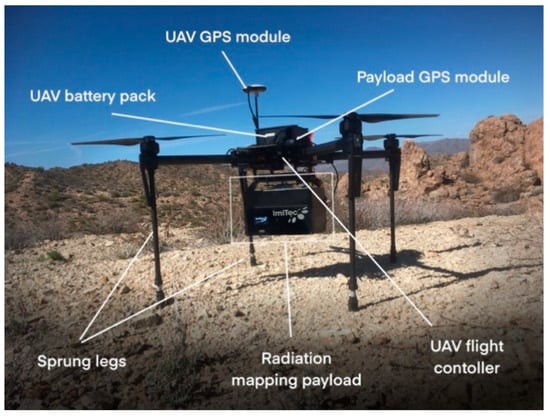
Figure 1.
Photograph of the aerial platform consisting of the DJI M100 UAV with attached radiation mapping payload (comprising SIGMA-50 detector, external GPS module, radio datalink, single-point range-finger and associated control electronics).
Following rapid in-field plotting and interpolation of raw CPS data, ‘ground-truthing’ samples were collected from vein outcrops indicated to have elevated radioactivity levels versus local background (an image of the sampling location is shown in Figure S2, contained within this articles Supplementary Information). The arising samples, each of approximately 100 g mass (the locations of which are shown in Figure 3b), were subsequently annotated, packaged and recovered to the laboratory for elemental, species, radiological and mineralogical analysis/assessment.
2.3. Data Processing
Following collection, data processing was performed to allow for the potential sub-surface ore body distribution to be assessed. To produce a map of gross activity at 1 m above the ground, the total count rate measured every 0.1 s by the detection platform was first converted into counts per second (CPS) before being height corrected (using altitude measurements obtained by the onboard laser rangefinder) by applying previously derived normalization factors associated with radiation emitted from planar (non-point) sources [22]. Following the export of the raw data from the Imitec Ltd. capture software, the display of the data was performed using either the contour plot function within OriginLab Pro or gnuplot (using Python), with smoothing and interpolation factors of 0.05 and 1.0, respectively, displaying the output within ArcGIS—a schematic of the workflow is shown in Figure S3a, contained in this manuscripts accompanying the Supplementary Information. The use of ArcGIS represents an entirely arbitrary step in the process (with the potential of being replaced with additional Python modules or the use of any open-source GIS program, e.g., QGIS or GRASS GIS), and can hence be easily substituted within the workflow presented.
The analysis of the gamma-ray energies recorded by the spectroscopic detection system, over just the sum total of detection events, provided an enhanced fingerprint of ore deposits and their location/distribution, based upon the characteristic radiation they emit. Within a custom Python program, a ‘window’ function was applied to the spectral data obtained from across the entire site for specific gamma energies of isotopes associated with the U, Th and K series decay chains, the established and widely adopted gamma-ray energies and associated bins/windows are shown in Table 1 [23]. It should be noted, however, that the primary photopeak emission energies for K, (40K—1460 keV), U (214Bi—1765 keV), and Th (208Tl—2614 keV) were all outside of the energy range of the SIGMA-50 detector used as part of this proof-of-concept study. Therefore, lower energy emissions and the associated windows (including those of other radionuclides) from the U and Th decay chains were used to attribute the existence of such elements. To improve the signal–noise ratio, typical of airborne surveys, and yield spectra with discernible peaks for quantitative analysis, a background subtraction and smoothing filter was applied to the UAV-derived data, producing a plot consisting solely of the characteristic emission peaks (energy and intensity/magnitude).

Table 1.
Gamma-ray energies and associated spectral windows utilised for natural radionuclide mapping, modified from [23]. The primary windows typically used for spectroscopic identification of K, U and Th are all indicated (*).
Aerial imagery obtained from the downward-pointing camera installed on the UAV was post-processed using Agisoft™ Photoscan software to derive a highly accurate (sub-cm resolution) 3D model of the area, using the image reconstruction and analysis methodology detailed in (Connor et al. 2018b)—a summary of the process is additionally shown schematically in the Supplementary Figure S3b. A total of 247 images were rendered to obtain the topographic reconstruction of the 36,000 m2 site, with the methodology using the overlapping regions between each of the two-dimensional aerial images to extract a three-dimensional point cloud. Subsequently, an interconnect mesh is interpolated between these extracted points and imagery applied, using established mosaicking and image reconstruction methods [24,25]. This 3D model is then converted into a digital elevation model (DEM) and a textural overlay (from the aerial photos), then imported into ArcGIS to overlay the radiation data. The resultant DEM exhibits a spatial resolution of 1.36 cm/pixel with an RMS reprojection error of 1.64 pixels.
2.4. Laboratory Analysis
To calibrate and ‘ground-truth’ the aerially derived results with on-ground composition, a number of standard laboratory analytical techniques were applied to physical samples of ore material collected in the field, including the use of both a High Purity Germanium (HPGe) detector (for gamma-ray spectroscopy) and a scanning electron microscope (SEM) for compositional/elemental quantification. Supporting phase determination was determined via Raman spectroscopy. Details of the methodologies associated with these techniques are presented in the accompanying Supplementary Information.
3. Results
3.1. Radiation Distribution
A 2D contour map depicting the radiation intensity distribution (total counts) across the Wooley Mine site is shown in Figure 2a,b, contoured and un-contoured (for the 1 m grid), respectively. This contouring was supported by a number of on-ground measurements and transects to calibrate the aerial measurements/define the local variations and appropriate degree of associated interpolation. Owing to the general underlying lithology of the region (composed of magmatically evolved intrusive granitic rocks) the background count-rate (circa 200 CPS) is elevated in comparison to levels associated with elsewhere in much of the USA and UK. From this plot, however, despite the raised background levels, areas with elevated radioactivity are observed to be associated with three discrete regions on the site. The maximum activity detected on the mine site was found at the center of the site and survey areas, at 382 CPS—corresponding to a dose-rate of 0.80 µSv/hr, albeit highly localized in its spatial extent. Such a strong degree of localisation is to be expected from the surface manifestation of an ore deposit, having been intersected by steep surface topography.
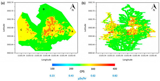
Figure 2.
(a) Radiation intensity (total counts) contour plot, and (b) un-contoured radiation intensity plot for the Wooley Mine site, derived using the unmanned aerial vehicles (UAV) at a survey height of 35 m above site minimum.
The results of post-processing the aerial imagery obtained by the UAV to derive a surface topographic render are displayed in Figure 3a, with the same 3-dimensional volumetric model overlain with the radiometric data shown in Figure 3b. An overview map detailing the respective locations of the figures contained within this manuscript is shown in Figure S4 (presented within this manuscripts accompanying the Supplementary Information), with the radiometric data comprising both Figure 2 and Figure 3b derived from the same raw dataset obtained in the field via the UAV radiation mapping platform. In Figure 3a, the topographic relief of the Wooley Mine site is evidenced, with a number of steep features delineated by narrow valleys and access roadways—the location of these local topographic features is seen to relate to the areas of elevated radioactivity, formerly identified. This localized association is illustrated through the product of rendering the ‘flat’ 2-dimensional radiation map of the site, as shown in Figure 2, over this 3-dimenstional reconstruction, to yield the plot shown in Figure 3b. Apparent from this plot is the distribution of radiation associated with regions several hundred meters in spatial extent on both the eastern and western border of the central topographic maximum on the site. Together with Figure 2, Figure 3b illustrates the elevated radiation levels, however, as not being correlated with linear features, as is typical, in general, of ore bodies and those within the region [17], which are more widespread and diffuse in their nature. Such a distribution is to be anticipated in this instance, as this below-surface mine and its formerly linear ore deposit(s) have since been significantly worked and disrupted—with the extracted (radioactive) ore material and tailings dispersed across the area. The absence of a statistical relationship between radiological intensity (CPS and µSv/hr) and landscape topography (here defined as mean altitude above sea level, ASL) is signified through an r-squared (r2) value of 0.0055.
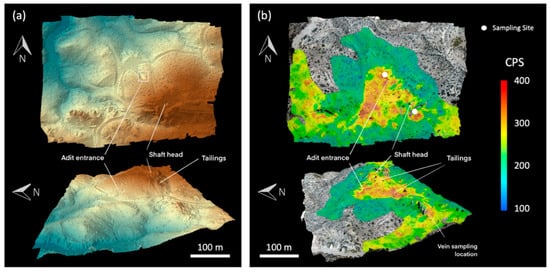
Figure 3.
(a) 3-dimensional photogrammetry reconstruction of the Wooley Mine site and survey area detailing the localized topographic features. (b) Photogrammetry model of the site (from (a)) rendered with the aerially derived radiation mapping results shown in Figure 2. The locations at which ore samples were obtained for subsequent mineralogical analysis are shown in (b).
Owing to the primary species mined at the Wooley Mine site being copper, rather than uranium, ores not containing economically appreciable Cu content (and potentially significant uranium load), were discarded downslope of the main shaft and adit, alongside extensive volumes of bulk (rock) spoil and ‘gangue’ minerals, on spoil heaps and also sporadically across the site. As such, the surface manifestation of radioactivity in this instance is ascribed predominantly to ‘anthropogenically derived’ tailings materials, alongside a surface-running vein outcrop, of lower but discernible radioactivity versus background. This vein outcrop, being physically harder than the surrounding country rock, stands proud in the terrain and can be distinguished in the digital elevation model.
The DEM also indicates the exact location of the main (vertical) shaft and the entrance to the horizontal adit, with coinciding downslope aprons of radiologically distinct spoil material which was deposited as a by-product/waste of the primary copper extraction process (a photograph of which is shown in Figure S5, available as part of this manuscript’s accompanying Supplementary Information). The delineation of such radiogenic ore material via aerial system is, therefore, shown.
3.2. Survey Spectral Analysis
To attribute the elevated radiation levels associated with the three formerly identified regions on the Wooley Mine site to uranium exploration, an analysis of the gamma-ray spectra derived from the composite surveys was undertaken. Resulting from the collection of over 38,000 individual gamma-ray spectra (obtained every 0.1 s) during the UAVs aerial mapping transects of the site, it was possible to derive/assay the contributing radionuclides from specific areas of interest across the Mine site. The background-removed (peak-isolated) spectra mathematically derived to highlight the specific photo-peak contributions within the full gamma-ray spectra obtained from each the four regions identified in Figure 2 (labelled A, B, C and D) are shown in Figure 4. These spectra correspond to the locations of the three regions of elevated activity (A, B, C) alongside a portion of the site to the south (D), where near-background (non-elevated) count rates were observed.
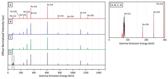
Figure 4.
Gamma-ray spectra (A, B, C and D) from the four regions identified within Figure 2, corresponding the three areas of elevated activity (A, B, C) alongside a portion of the mine site (D) to the south, where background (non-elevated) count rates were measured. Inset; low-energy region (0–300 keV) of the gamma-ray spectra (regions A, B, C and D) illustrating the Pb and Ra peaks.
Observable in Figure 4 is the similarity of the peak-isolated spectra derived for the three regions of elevated activity: A, B and C. Although a number of the higher-energy and more characteristic emissions (as shown formerly in Table 1) are likely to exist above the maximum detectable energy of the SIGMA-50 device of 1500 keV (1.5 MeV), the peaks (of varying intensities) measured by their UAV-mounted detector are those of 226Ra, 214Bi, 211Bi, 214Pb, 224Ra and 212Pb. The contributions within the three spectra from 214Bi, 214Pb and 226Ra are all emissions associated with the 238U decay chain, the main and most abundant isotope of uranium. An additional contribution to the 214Pb peak at 350 keV (resulting in a very minor broadening) is a consequence of the emission from 211Bi—a decay chain product of the considerably less abundant isotope of uranium: 235U. The further peaks evident within each of the spectra (224Ra and 212Pb) are not the result of the gamma emissions of daughter products from uranium series decay chains, but are instead from the 232Th decay series. Such thorium series emissions are not entirely unexpected from a site such as Wooley Mine. Despite being known as a copper prospect with trace uranium mineralization, as both uranium and thorium are commonly associated with one another and ions of each element readily substitute within a minerals’ lattice, thorium-containing minerals would have likely occurred to a minor extent alongside the more common copper and uranium composition material.
The processed (peak-isolated) spectrum derived from the summation of aerial measurements collected from region D in Figure 2, is shown also in Figure 4. Like the spectrum derived from regions A, B and C, the peaks present within this intensity normalised spectrum of a region approximately 100 m north from the highest levels radioactivity are the result of emissions from the same radioisotopes; 226Ra, 214Bi, 211Bi, 214Pb, 224Ra and 212Pb. While the activity of region D is 50% of that evidenced at positions A, B and C (190 CPS vs. 382 CPS), a combination of (i) lower-activity material outcropping or having been distributed at this location, and (ii) the detection of highly penetrating gamma-ray emissions from the elevated activity regions to the south, together contribute to the spectral signal, with the primary contributions from species within the 238U series decay chain, whereas the peak-isolated spectrum of D is largely identical to those of A, B and C—one difference that does exist is associated with the lower-energy region of the spectrum (highlighted), below 100 keV. This signal is ascribed to result from an increased background contribution and greater Compton (elastic) Scattering within the detector volume, a consequence of the more indirect and diffuse nature of the photons incident onto the detector, following increased prior interaction events.
3.3. Laboratory Gamma-Ray Spectroscopy
To support in-field spectroscopy measurements, a complementary laboratory derived gamma-ray spectroscopy analysis was also made of 100 g of bulk sample obtained from the region of elevated activity at the center of the site, as marked in Figure 3b. The results of this laboratory analysis on an example ore deposit sample (‘B’ in Figure 2a) are shown in Figure 5. In contrast to spectra derived from contamination events such as Fukushima and Chernobyl, which are associated with anthropogenically derived isotopes such as 134Cs and 137Cs that emit mono-energetic gammas, the spectrum of the representative ore sample shown in Figure 5, contains a large number of peaks, from the formerly identified suite of decay chain isotopes. As previously depicted within Figure 4, The largest number of peaks and those with the greatest intensity are associated with 214Bi and 214Pb, short-lived nuclides within the 238U decay chain. A minor peak contribution at 350 keV/351 keV, shown in Figure 4, is also observed within this laboratory characterization, resulting from the 211Bi emission, a gamma-emitting radionuclide in the less abundant 235U decay chain.
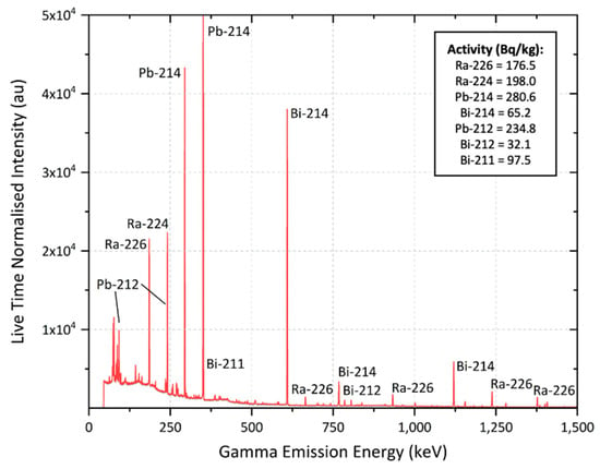
Figure 5.
Gamma-ray spectrum (normalised to the system live time) of an ore sample obtained from Wooley Mine, analysed using the laboratory cryogenically cooled HPGe system. Inset; activity contributions (in Bq/kg) of the ingrown daughter species.
While the peaks (both occurrence and intensity) observed within the laboratory derived spectrum presented in Figure 5 largely match the aerially produced results (Figure 4), minor differences are observed at lower energies. Resulting from the suppressed Compton continuum/scattering within the HPGe spectrum, additional low-energy 212Pb peaks are now observed, associated with the decay of 232Th, further supporting the aerial results and their occurrence alongside U (and Cu) at the Wooley Mine site. Such a gamma-ray spectra is indicative of uranium mineralogies such as uraninite (pitchblende), autunite, torbernite and coffinite, although further compositional information is required to ascribe the correct mineral species.
3.4. Electron Microscopy and Energy Dispersive Spectroscopy
Confirmation of the composition and mineralogy of the physical ore material was provided by subsequent electron microscopy characterisation of the sample examined previously via laboratory HPGe gamma-ray spectroscopy, with the sample embedded in an epoxy resin mount, sectioned and polished in preparation for microscopy analysis—the results of which are shown in Figure 6 and Figure 7. Figure 6a,b show mixed backscattered electron (BSE) and secondary electron (SE2) images of white uranium-rich grains, each approximately 2.5–5 µm in maximum dimension, contained within the surrounding (darker colored) bulk matrix. The composition of these grains, constituted by uranium and oxygen, in contrast to the majority Si, Cu and O groundmass that encompasses them, is illustrated by the EDS elemental maps shown in Figure 6c–f.
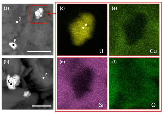
Figure 6.
(a) and (b) Mixed Backscattered electron (BSE) and Secondary electron (SE2) images showing a typical U composition (high Z number) mineral grain (white) against the surrounding (low Z number) matrix (dark), EDS compositional maps of the mineral grain identified in (a), detailing the distribution of (c) U, (d) Si, (e) Cu, and (f) O. Scale bars = 5 µm. The locations at which EDS point analysis results (A–E) were also obtained and identified, as shown in Figure 7.
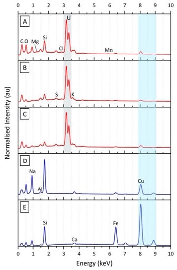
Figure 7.
EDS compositional spectra of three of the mineral grains (A–C) identified formerly in Figure 6, showing their combined U and Cu composition, alongside the other common rock-forming constituents comprising the surrounding bulk matrix (D,E). The composition of these “accessory phases” (D,E) is subsequently elucidated via Raman spectroscopy analysis, the results of which are presented in Figure 8.
An EDS spectrum of the uranium mineral grains, shown as A, B and C in Figure 6, is presented in Figure 7, with a compositional quantification of A detailed in Table 2. As anticipated and evidenced by both the EDS spectrum and the results of Table 2, uranium and copper are observed to occur at the greatest abundances outside of the typical low Z-number, rock-forming, elements (e.g., Si, Al, K, O, Ca). Despite the size of the incident electron beam (of high accelerating voltage and associated probe current) being focused down to a diameter of approximately 1 μm, a contribution to the compositional (characteristic X-ray) signal of the U material will result from the surrounding bulk sample due to inherent scattering/secondary interactions within the material. This will, therefore, manifest in a degree of variation across the (in-situ) U grains, with varying light element components.

From this EDS analysis (both point and mapping) of the uranium component (points A, B and C), it is possible to ascribe a mineralogy to the material. The absence of P as a constituent within the uranium mineral signifies that it is not the common green hydrated copper uranyl phosphate mineral torbernite (Cu(UO2)2(PO4)2·8-12H2O). A lack of Si associated with the U abundance alongside appreciable levels of O (as highlighted by the EDS maps of Figure 6) suggests that the U mineral grains are not a uranium-silicate mineral, but rather simply composed of just U and O, as the major uranium ore of uraninite (UO2—U3O8). In contrast to the accessory phases that accompany the U mineral grains (Figure 7D,E) which contain markedly higher Si and Cu content, as formerly stated, such light element signals are likely to result from interactions with the surrounding matrix material—which are greater following interactions with high Z number species.
As is shown in the elemental maps of Figure 6d–f, in addition to the EDS spectra of points D and E (Figure 6a,b) shown in Figure 7, the bulk minerology surrounding the uranium minerals is composed of Si, Cu, Fe and O, alongside a number of other constituent light elements at lower concentrations. This non-uranium mineralogical assemblage likely represents one of the mine’s ore (or gangue) phases, known to occur at the site [17,18]—such as Chalcocite, Chalcopyrite, Chrysocolla, Malachite, Hematite or Quartz.
3.5. Raman Spectroscopy
Further to the EDS compositional analysis, complimentary Raman spectroscopy results derived from two discrete regions of the crushed Wooley Mine ore sample (surrounding D and E in Figure 6) are shown in Figure 8a,b, analysed between 100 and 1500 cm−1. Within Figure 8a, the characteristic peaks at 400, 677 and 1328 cm−1 of hematite (α-Fe2O3); 461 cm−1 of quartz (SiO2); 1010 cm−1 of gypsum (CaSO4·H2O); and 1117 cm−1 of phosphate ([PO4]3−) are observed, aligning with the EDS elemental analysis results (Figure 7) of the regions surrounding the uranium inclusions. This low-intensity emission signal is in contrast to the Raman signatures observed for two further (sub) regions of the sample shown in Figure 8b. From this plot, clear spectra from both quartz (SiO2) and hematite (α-Fe2O3) are observed—corresponding to optically light and dark regions within the vein sample, respectively. Such mineral identification corroborates the EDS elemental analysis undertaken, with Si, Cu, Ca, (Na) and Fe identified via EDS assigned via Raman spectroscopy.
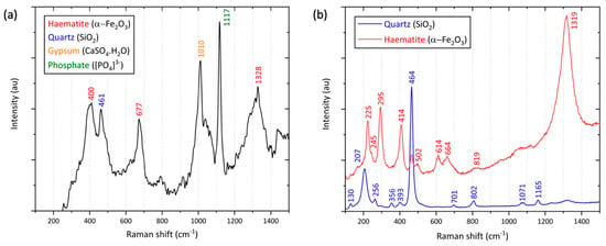
Figure 8.
(a) and (b) Raman spectra of two regions within the crushed ore sample, illustrating the additional iron (haematite), quartz, gypsum and phosphate mineral phases that exist alongside the uranium and copper components identified via EDS, in Figure 7.
While EDS was able to identify and attribute the U to a specific mineral (likely uraninite), it was not possible to confirm this via Raman spectroscopy, however, Raman was capable of fingerprinting a number of the accompanying accessory mineral phases, with the mineralogy not assignable via EDS analysis. Although not the full suite of mineral species known to exist at Wooley Mine (chrysocolla, malachite, chalcocite, chalcopyrite, quartz, hematite, and limonite [19]), Raman spectroscopy has definitively identified two such minerals from a small, surface-exposed vein sample, alongside signatures from sulphate and phosphate-containing mineral species, assigning phases to the elemental constituents identified via EDS analysis.
4. Discussion
This study sought to establish whether an existing and established UAV and radiation mapping compliment more typically applied to emergency response and monitoring scenarios could be applied to the prospecting of sub-surface ore deposits. Resulting from such metallic (in this instance, Cu) deposits exhibiting a radiogenic signature as a consequence of their association with naturally occurring radionuclides (U and Th) from the same igneous precursor material, it has been shown that this aerial technology is capable of accurately assessing the spatial distribution and associated radiogenic signatures of commercially valuable surface/near-surface ore bodies—albeit, in this instance, the areas of most significant radiological anomaly were anthropogenic in origin (TNORM), related to mine waste tailings.
It is, however, notable that the surface outcrop of a copper-containing quartz vein, running linearly across the site, is delineated by the 3D radiation map and informed the location of in-field rock/vein sampling. A comparative overlay of historic mine records with both the radiation map and DEM derived from this work is shown in Figure 9 to confirm the results of this concept-driven study, illustrating the strong degree of correlation between such legacy records of the subsurface ore body deposit and current in-field observations obtained with the UAV, therefore illustrating the applicability of this low-cost and eminently deployable field-based prospecting tool.
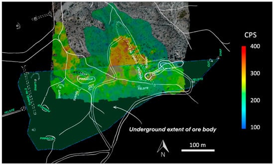
Figure 9.
Overlay comprising the historic mine plan (from Arizona Department of Mines and Mineral Resources Mining Collection, (2002)) with the UAV-derived DEM and radiation intensity maps.
Following earlier studies utilizing UAVs to investigate contamination distribution and evolution associated with historic UK mine operations [14] and radiocesium fallout from Japan’s Fukushima Daiichi Nuclear Power Plant accident [26,27], these results advocate that this low-cost aerial system can be deployed as a valuable and rapidly deployable component of the wider exploration ‘toolkit’—namely on more local scales, by non-specialist users and those without significant financial means to undertake more costly regional-scale mapping. Such highly automated and user-intuitive devices specifically represent a ‘gate-way capability’ for less economically developed countries to survey and evaluate their potentially exploitable mineral wealth that was formerly inaccessible owing to the prohibitive costs of conventional (manned fixed-wing and helicopter) aerial survey platforms. The total capital costs of this UAV system are estimated at <5% of manned aerial equivalents, with ongoing operational expenses, personnel training and platform maintenance additional costs not associated with the UAV capability developed and deployed in this work.
5. Conclusions and Future Work
This work has shown that there is an eminently translatable application of multi-rotor UAV’s, formerly used for emergency response scenarios and anthropogenic applications, to mineral resource detection and mapping. Such a platform presents numerous advantages over existing survey methodologies, including reduced costs, enhanced on-ground spatial resolution and an ability to undertake such monitoring with significantly reduced operator training.
Future work in this area will seek to transition autonomous fixed-wing airframes equipped with miniaturised radiation mapping payloads and the next generation of detectors (such as those recently used to determine the distribution of radiation within the Chernobyl Exclusion Zone [28]), to resource exploration. Operating at higher altitudes and greater survey velocities than the multi-rotor UAVs deployed in this exploratory work (hence avoiding topographic features), these fixed-wing systems can additionally attain considerably greater flight durations, therefore covering larger survey areas per flight and charge of its batteries. Future work will also seek to utilise scintillator detector materials with higher density and quantum efficiency to enable measurement of gamma photons at energies up to 3 MeV, which would enable direct measurement of the primary photo-peaks for K, (40K—1460 keV), U (214Bi—1765 keV) and Th (208Tl—2614 keV), thereby allowing more efficient spatial discrimination of emissions from the different radioelements.
Supplementary Materials
The following are available online at https://www.mdpi.com/2072-4292/12/21/3562/s1. Supplementary Methods. Figure S1: Satellite maps detailing the location of the Wooley Mine site in relation to nearby population centers. Figure S2: Photograph of the surface mineral vein, exhibiting elongated quartz-rich regions alongside associated Cu-rich green inclusions. Figure S3: (a) Flow chart of the radiological data processing undertaken to convert UAV-derived measurements into standard (altitude corrected) values of activity and dose rate. (b) Flow chart of the aerial imagery processing undertaken to convert to overlapping photos into a 3-dimensional photo-realistic topographic site model. Figure S4: Overview aerial map of the Wooley Mine site, illustrating the relative locations of the figures presented within this manuscript. Figure S5: Photograph (facing north) of the topographic high on the Wooley Mine site, comprising the tailings piles and the former vertical (main) shaft entrance on the top of the hillside.
Author Contributions
P.G.M.: conceptualization, methodology, validation, investigation, formal analysis, writing—original draft, writing—review and editing, project administration. D.T.C.: software, validation, methodology, formal analysis, writing—original draft, data curation. N.E.: formal analysis, data curation, writing—original draft. A.E.-T.: investigation, formal analysis, writing—original draft. D.M.-S.: investigation, formal analysis, software. C.P.J.: investigation, formal analysis. D.K.K.: resources, writing—original draft, writing—review & editing, resources. T.B.S.: funding acquisition, project administration, resources, supervision, conceptualization, writing—original draft, writing—review & editing. All authors have read and agreed to the published version of the manuscript.
Funding
The authors wish to acknowledge the funding received by the Engineering and Physical Sciences Research Council, EPSRC (grant references: EP/R02572X/1 and EP/R026084/1). The electron microscope used in this analysis was funded by the EPSRC (grant reference: EP/K040340/1).
Acknowledgments
P.G.M. wishes to acknowledge the Royal Academy of Engineering for the Research Fellowship under which this work was undertaken. T.B.S. wishes to acknowledge the funding received from the Royal Academy of Engineering for his Research Chair at the University of Bristol.
Conflicts of Interest
The authors declare no conflict of interest. The funders had no role in the design of the study; in the collection, analyses, or interpretation of data; in the writing of the manuscript, or in the decision to publish the results.
Data Availability Statement
The raw and processed data required to reproduce these findings are available to download from; Martin, Peter (2020), “Radiological identification of near-surface mineralogical deposits using low altitude unmanned aerial vehicle”, Mendeley Data, V1, doi: 10.17632/bydr4bkns3.1.
References
- Jowitt, S.M.; Werner, T.T.; Weng, Z.; Mudd, G.M. Recycling of the rare earth elements. Curr. Opin. Green Sustain. Chem. 2018, 13, 1–7. [Google Scholar] [CrossRef]
- Ridley, J. Ore Deposit Geology; Cambridge University Press: Cambridge, UK, 2013; ISBN 9781107022225. [Google Scholar]
- Gadallah, M.R.; Fisher, R. Exploration Geophysics, 1st ed.; Springer-Verlag Berlin Heidelberg: Heidelberg, Germany, 2009; ISBN 978-3-540-85159-2. [Google Scholar]
- Kearey, P.; Brooks, M.; Hill, I. An Introduction to Geophysical Exploration, 3rd ed.; Blackwell Science: Hoboken, NJ, USA, 2002; ISBN 9780632049295. [Google Scholar]
- Beamish, D. Environmental radioactivity in the UK: The airborne geophysical view of dose rate estimates. J. Environ. Radioact. 2014, 138, 249–263. [Google Scholar] [CrossRef] [PubMed]
- Moon, C.J. Geochemical exploration in Cornwall and Devon: A review. Geochem. Explor. Environ. Anal. 2010, 10, 331–351. [Google Scholar] [CrossRef]
- Moxham, R.M. Airborne radioactivity surveys in geologic exploration. Geophysics 1960, 25, 408–432. [Google Scholar] [CrossRef][Green Version]
- IAEA. Radioelement Mapping; International Atomic Energy Agency: Vienna, Austria, 2010. [Google Scholar]
- Grasty, R. Environmental Monitoring by Airborne Gamma Ray Spectrometry, Experience at the Geological Survey of Canada. Appl. Uranium Explor. Data Tech. Environ. Stud. 1995. [Google Scholar]
- Minty, B.R.S. Fundamental of airborne gamma-ray spectrometry. J. Aust. Geol. Geophys. 1997, 17, 39–50. [Google Scholar]
- Connor, D.; Martin, P.G.; Scott, T.B. Airborne radiation mapping: Overview and application of current and future aerial systems. Int. J. Remote Sens. 2016, 37, 5953–5987. [Google Scholar] [CrossRef]
- Fortin, R.; Hovgaard, J.; Bates, M. Airborne gamma-ray spectrometry in 2017: Solid ground for new development. In Proceedings of the Exploration 17: Sixth Decennial International Conference on Mineral Exploration, Toronto, ON, Canada, 22–25 October 2017; pp. 129–138. [Google Scholar]
- Muchiri, N.; Kimathi, S. A review of applications and potential applications of UAV/proceedings of sustainable research and innovation conference. In Proceedings of the Sustainable Research and Innovation Conference, Seville, Spain, 14–16 November 2016; pp. 280–283. [Google Scholar]
- Martin, P.G.; Payton, O.D.; Fardoulis, J.S.; Richards, D.A.; Scott, T.B. The use of unmanned aerial systems for the mapping of legacy uranium mines. J. Environ. Radioact. 2015, 143, 135–140. [Google Scholar] [CrossRef] [PubMed]
- Salek, O.; Matolin, M.; Gryc, L. Mapping of radiation anomalies using UAV mini-airborne gamma-ray spectrometry. J. Environ. Radioact. 2018, 182, 101–107. [Google Scholar] [CrossRef] [PubMed]
- Malehmir, A.; Dynesius, L.; Paulusson, K.; Paulusson, A.; Johansson, H.; Bastani, M.; Wedmark, M.; Marsden, P. The potential of rotary-wing UAV-based magnetic surveys for mineral exploration: A case study from central Sweden. Lead. Edge 2017, 36, 552–557. [Google Scholar] [CrossRef]
- Arizona Department of Mines and Mineral Resources Mining Collection AZMILS Data—ABC Group; Phoenix; 2002. Available online: http://docs.azgs.az.gov/OnlineAccessMineFiles/A-B/ABCgroupPinal333a.pdf (accessed on 21 September 2020).
- USGS Wooley Mine (MRDS #10046284) CU. Available online: https://mrdata.usgs.gov/mrds/show-mrds.php?dep_id=10046284 (accessed on 30 March 2020).
- The Diggings Wooley Copper Mine Near Kelvin, Arizona. Available online: https://thediggings.com/mines/15717 (accessed on 1 April 2020).
- Connor, D.T.; Martin, P.G.; Pullin, H.; Hallam, K.R.; Payton, O.D.; Yamashiki, Y.; Smith, N.T.; Scott, T.B. Radiological comparison of a FDNPP waste storage site during and after construction. Environ. Pollut. 2018, 243, 582–590. [Google Scholar] [CrossRef] [PubMed]
- Martin, P.G.; Connor, D.; Payton, O.D.; Leal-Olloqui, M.; Keatley, A.C.; Scott, T.B. Development and validation of a high-resolution mapping platform to aid in the public awareness of radiological hazards. J. Radiol. Prot. 2018, 38, 329–342. [Google Scholar] [CrossRef] [PubMed]
- Connor, D.T.; Martin, P.G.; Smith, N.T.; Payne, L.; Hutton, C.; Payton, O.D.; Yamashiki, Y.; Scott, T.B. Application of airborne photogrammetry for the visualisation and assessment of contamination migration arising from a Fukushima waste storage facility. Environ. Pollut. 2018, 234, 610–619. [Google Scholar] [CrossRef] [PubMed]
- Minty, B.R.S.; Luyendyk, A.P.J.; Brodie, R.C. Calibration and data processing for airborne gamma-ray spectrometry. J. Aust. Geol. Geophys. 1997, 17, 51–62. [Google Scholar]
- Li, X.; Feng, R.; Guan, X.; Shen, H.; Zhang, L. Remote Sensing Image Mosaicking: Achievements and Challenges. IEEE Geosci. Remote Sens. Mag. 2019, 7, 8–22. [Google Scholar] [CrossRef]
- Wan, Y.; Wang, D.; Xiao, J.; Wang, X.; Yu, Y.; Xu, J. Tracking of vector roads for the determination of seams in aerial image mosaics. IEEE Geosci. Remote Sens. Lett. 2012, 9, 328–332. [Google Scholar] [CrossRef]
- Martin, P.G.; Payton, O.D.; Fardoulis, J.S.; Richards, D.A.; Yamashiki, Y.; Scott, T.B. Low altitude unmanned aerial vehicle for characterising remediation effectiveness following the FDNPP accident. J. Environ. Radioact. 2016, 151, 58–63. [Google Scholar] [CrossRef] [PubMed]
- Martin, P.G.; Kwong, S.; Smith, N.T.; Yamashiki, Y.; Payton, O.D.; Russell-Pavier, F.S.; Fardoulis, J.S.; Richards, D.A.; Scott, T.B. 3D unmanned aerial vehicle radiation mapping for assessing contaminant distribution and mobility. Int. J. Appl. Earth Obs. Geoinf. 2016, 52, 12–19. [Google Scholar] [CrossRef]
- Connor, D.T.; Wood, K.; Martin, P.G.; Goren, S.; Megson-Smith, D.; Verbelen, Y.; Chyzhevskyi, I.; Kirieiev, S.; Smith, N.T.; Richardson, T.; et al. Radiological Mapping of Post-Disaster Nuclear Environments Using Fixed-Wing Unmanned Aerial Systems: A Study From Chornobyl. Front. Robot. AI 2020, 6, 14. [Google Scholar] [CrossRef]
Publisher’s Note: MDPI stays neutral with regard to jurisdictional claims in published maps and institutional affiliations. |
© 2020 by the authors. Licensee MDPI, Basel, Switzerland. This article is an open access article distributed under the terms and conditions of the Creative Commons Attribution (CC BY) license (http://creativecommons.org/licenses/by/4.0/).