Abstract
Unmanned Aerial Vehicles (UAVs), although hardly a new technology, have recently gained a prominent role in many industries being widely used not only among enthusiastic consumers, but also in high demanding professional situations, and will have a massive societal impact over the coming years. However, the operation of UAVs is fraught with serious safety risks, such as collisions with dynamic obstacles (birds, other UAVs, or randomly thrown objects). These collision scenarios are complex to analyze in real-time, sometimes being computationally impossible to solve with existing State of the Art (SoA) algorithms, making the use of UAVs an operational hazard and therefore significantly reducing their commercial applicability in urban environments. In this work, a conceptual framework for both stand-alone and swarm (networked) UAVs is introduced, with a focus on the architectural requirements of the collision avoidance subsystem to achieve acceptable levels of safety and reliability. The SoA principles for collision avoidance against stationary objects are reviewed and a novel approach is described, using deep learning techniques to solve the computational intensive problem of real-time collision avoidance with dynamic objects. The proposed framework includes a web-interface allowing the full control of UAVs as remote clients with a supervisor cloud-based platform. The feasibility of the proposed approach was demonstrated through experimental tests using a UAV, developed from scratch using the proposed framework. Test flight results are presented for an autonomous UAV monitored from multiple countries across the world.
1. Introduction
We live in the ‘era’ of Unmanned Aircraft Systems (UAS), an all-encompassing term that includes the aircraft or the UAV, the ground-based controller (the person or software agent operating the machine), and the communications systems connecting the two [1]. Furthermore, new solutions are being proposed, allowing one to interconnect the different components of this system using cloud-oriented architecture [2].
Today, the UAVs are revolutionizing the world and businesses in a way that hardly anyone could have ever imagined [3,4]. This rapid evolution of UAVs and more importantly their commercial application in an ever-larger spectrum of scenarios, increases the need for safer and more reliable solutions [5,6,7,8]. At the same time, the incremental developments of sensing technologies (e.g., thermal, multispectral, and hyperspectral) in multiple areas may change parts of society by creating new solutions and applications [9,10,11,12,13].
In order to safely deploy UAVs in an urban environment, UAVs must reach the same level of reliability and safety as cars [14]. This level of safety and reliability must be assured regardless of the operation conditions and occurrence of unexpected events. This leads to the obvious conclusion that, just as for other autonomous vehicles, it is required to develop a collision avoidance architecture that is agnostic of the environment constrains, and is capable of finding solutions to unexpected events in real-time. The lack of such robust architectures has led to multiple disasters in the past [15,16,17,18,19,20,21], which will naturally increase with the expected exponential growth in the number of UAVs that will be deployed (both by consumers and companies). In this paper, a robust architecture, part of a complete Framework for Fully Autonomous UAVs (FFAU) is proposed along with complete implementation (both software and hardware) that satisfy the functional and technical requirements of the proposed architecture. The increased safety of the proposed framework allows new and interesting usage scenarios such as the long distance remote control of UAVs. Furthermore, a novel Dynamic Collision Avoidance algorithm is proposed, which utilizes a Convolutional Neural Network (CNN) to extract features from video frames, and a Recursive Neural Network (RNN) that takes advantage of the video temporal characteristics capable of estimating if there is an incoming collision, such as the one depicted in Figure 1. This figure illustrates two frames from a video, retrieved from the ColANet dataset [22], that presents a kid kicking a ball into a UAV.
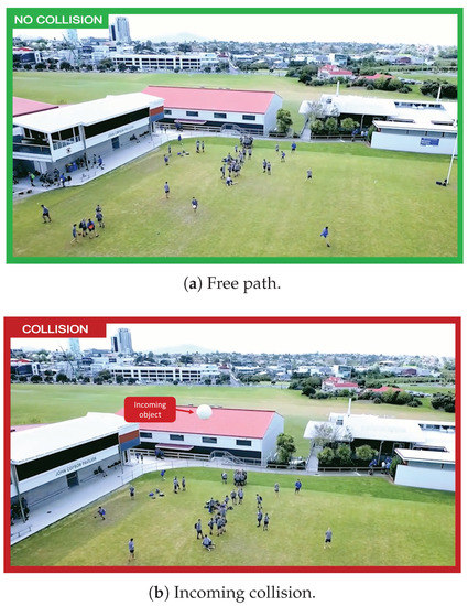
Figure 1.
Novel Dynamic Collision Avoidance Detection. The images represent two frames from the same video, where a boy kicks a ball into a UAV.
There are quite a few attempts to integrate UAVs into an architecture that links different UAVs modules and a cloud platform. The architecture presented in [23] covers three main topics: Air traffic control network, cellular network, and the Internet. The layered architecture provides services for different UAV applications, such as surveillance or search and rescue. The paper does not present any implementation of the proposed architecture and only outlines general concepts of the IoD (Internet-of-Drones), which later had a partial implementation [2]. Neither papers gave much importance to a key factor: The UAV itself. Contrarily, this paper analyzes in greater depth the UAV functional blocks without disregarding the equally important cloud connection.
A model of UAV usage in natural disasters was presented by Apvrille [24]. It helps rescuers find victims after a disaster. The proposed system addresses the development of autonomous UAV missions based on onboard image processing rather than controlling the UAV over the cloud or offloading computation to a remote server.
Mahmoud et al. proposed a model for collaborative UAVs [25] that maps cloud computing resources to the UAVs’ resources. Additionally, essential services and customized services were proposed, as the option to access UAVs resources over the Internet and control their mission. A high-level description of the system architecture, components, and services are presented, but it lacks detail on the implementation and results. Continuing this work, a Resource-Oriented Architecture (ROA) approach that represents the resources and services of UAVs was developed [26,27]. A prototype was implemented using an Arduino that emulates a UAV and its resources. However, this approach is very distant from a true experimental prototype and does not represent a sufficient proof of concept of real UAVs, and therefore does not demonstrate the feasibility of the approach.
Out of the scope of this related work are detailed descriptions of some concepts which the authors consider to be prior knowledge both in the areas of Robotics and Cloud, such as MAVLink protocol [28], Robotic Operation System (ROS) [29], Back-End (BE) [30], Web Application (WA) [30], docker [31], and kubernetes [32,33].
The rest of this paper is structured in the following sections: Section 2 introduces a framework for the safe operation of UAVs. The main novelties of this framework are collision avoidance and cloud blocks, which are detailed respectively in Section 3 and Section 4 respectively. Section 5 describes the experimental testing of concrete implementation (both software and hardware) of the proposed framework, and analyzes the data collected, which validates our approach and implementation. The paper presents its main conclusions and possible future research work in Section 6.
2. Framework for Fully Autonomous UAVs
This paper proposes the architecture depicted in Figure 2. The core elements are implemented on top of the ROS framework and make use of its abstractions and message passing systems to implement all necessary features [29]. The communication between blocks is done throughout ROS topics using the publisher/subscriber paradigm. The cloud platform, named Beyond Skyline, is a cloud platform that mimics a UAV Radio Command with the advantage that the pilot can control a UAV remotely through the internet. The pilot and the UAV need only an internet connection to the platform.
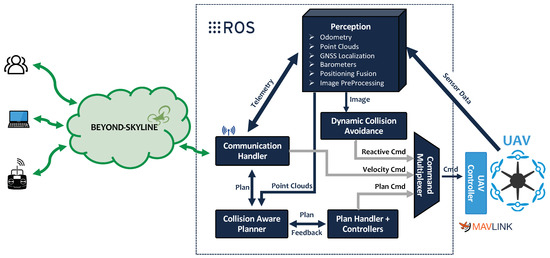
Figure 2.
Architecture of the framework for fully autonomous Unmanned Aerial Vehicles (UAVs).
Multiple software components are necessary for the development of a desirable (i.e., safe and reliable) UAV system. The ROS libraries were used for the modules running in the UAV, since it allows high flexibility and easier integration of future additional features. Moreover, it provides several off-the-shelf nodes that can be adjusted or reused to fit new purposes. The remainder of this section uses some of the terms intrinsic to ROS to explain each component represented in Figure 2. Additional details can be found alongside the source-code (at https://gitlab.pdmfc.com/drones/ros1/heifu).
2.1. Perception
Perception is the core block of the presented architecture. It encapsulates a set of functionalities that can be broken down into several nodes (usually one per each sensor), and higher-level nodes take input data from those that are directly handling the physical sensors.
The nodes that handle sensors directly are the following:
- Camera Node: Receives data from the camera and publishes it in a sensor image message format. This looks like a rather simple node, but it can be extremely complex. ROS passes images in its own message format, but many developers use images nodes bundled with different image processing libraries such as OpenCV [34];
- Odometry Node: This node can estimate the UAV position relative to its starting point. This can be done by using the UAV motion sensors data, performing estimations via visual odometry, or by using any sort of fusion algorithm that mixes methods. The data from this node is published on a message format denominated navigation odometry messages;
- IMU Node: The Inertial Measurement Unit (IMU) is responsible for handling the IMU sensors (accelerometer, gyroscope, magnetometer, and barometer) and periodically publishes sensor IMU messages to the ROS network;
- GNSS Node: Obtains data from the Global Navigation Satellite System (GNSS) and periodically publishes navigation messages on the ROS network.
In each node, filtering algorithms can be applied before publishing the data on the ROS network. It is important to filter erroneous readings from sensors and avoid polluting the top-level nodes with noise. Thus, on top of the first set of perception nodes, additional nodes can be developed, which use the filtered data. Some examples are positioning nodes [35], 3D nodes [36] (using structure from motion), or depth images to point cloud nodes [37].
2.2. Collision Aware Planner
The Collision Aware Planner (CAL) module is responsible for establishing a safe path. This module receives one or multiple coordinates and generates a path between those coordinates, taking into account the data from the perception layer (obstacles point-clouds). In a long autonomous mission, the CAL creates a trajectory between the two waypoints of the global mission. These trajectories are its output and consist of an array of georeferenced trajectory waypoints.
There are multiple forms to approaching the planning problem, as described by Galceran et al. [38]. The majority of SoA algorithms assume that the world can be modeled as a simple planar surface. Hert et al. [39] applied 2D knowledge to the 3D environment and some other methods to approach navigating with obstacle avoidance. Another method consists on interpolating the goal points given by the user and setting escape callbacks that enter in play whenever an obstacle is detected [40]. Section 3 will add additional detail regarding this topic. The CAL produces a trajectory that is a sequence of points with distance tolerances and updates the plan handler.
2.3. Plan Handler
Based on the CAL output, the plan handler interpolates the trajectory points with movement constraints and command actions. The plan handler node receives as input the joint state data from the UAV actuator’s encoders and an input set point. It uses a generic control feedback loop mechanism, typically a PID controller, to control the output. Since the number of joints of a UAV is usually simple, it is possible to create a standard action controller to translate the trajectory produced by this CAL into commands for the UAV controller.
2.4. Command Multiplexer
Prioritizing safety and control topics is a mandatory precaution in nowadays’ UAVs. Safety requires one to be able to automatically switch from autonomous behavior to manual control when pushing any button of a remote controller. Therefore, all input sources must be multiplexed into a single convergence point that communicates with the hardware controller.
The Command Multiplexer (CM) subscribes to a list of topics, which are publishing commands and multiplexes them according to a priority criteria. The input with the highest priority controls the UAV, becoming the active controller. The active controller can be changed by timeout (no response from an input) or topic locking (some inputs might be locked, being discarded). In practice, the node will take multiple input topics from different issuers and output the messages of the issuer with the highest priority (blocking the others). This is particularly useful when the UAV is flying autonomously and the pilot wants to take control of the UAV. Any command of the pilot will make him the active controller if the pilot is set with the highest priority.
2.5. Dynamic Collision Avoidance
The Dynamic Collision Avoidance (DCA) node is a novelty that distinguishes the FFAU from SoA frameworks, by improving safety. The core idea is that it implements the logic associated with unplanned actions that require immediate attention. For instance, if someone throws an object at the UAV while it is executing an autonomous mission, this node is responsible for forcing the UAV to change its trajectory and avoid the obstacle.
To accomplish this, it receives the live video stream information from the perception block and when an incoming collision is detected, it sends commands to the CM with high priority. On the proposed DCA algorithm, a set of Deep Neural Networks (DNN) are combined to achieve this result.
The collision avoidance algorithms require the UAV positioning to be coupled with image processing, since the motion drift caused by inertia can easily lead the DCA node to miscalculate a safe trajectory around an incoming object.
This paper introduces a novel DCA node for moving object detection and a collision avoidance algorithm that uses data from a standard camera, fully described in Section 3. The node is optional to the architecture and will only handle incoming collisions.
2.6. Communication Handler
In order to communicate with this framework, a communication module translates ROS publisher/subscriber into websockets. By doing this, it is possible to control a fleet of UAVs from any distance from the Beyond Skyline platform (the developed Beyond-Skyline platform can be accessed by the link—https://beyond-skyline.com/). The module also handles the handover between WiFi, 4G, and 5G. This is done by creating a stream in all available communication channels and by always using the one with the best connectivity. When the UAV is authenticated, it receives a dedicated channel to stream video and audio data using the Real-time Transport Protocol (RTP) [41].
3. Collision Avoidance
Creating a path planning from location A to location B, while simultaneously avoiding obstacles and reacting to environment changes are simple tasks for humans but are not so straightforward for a UAV. These tasks present challenges that each UAV needs to overcome to become fully autonomous. A UAV uses sensors to perceive the environment (up to some degree of certainty) and to build or update its environment map. To determine motion actions that lead to the desired goal location, it can use different decision and planning algorithms. In the process of path planning, the UAV’s kinematic and dynamic constraints should be considered.
Shortest paths discovery is used to solve problems in different fields, from simple spatial route planning to the selection of an appropriate action sequence that is required to reach a certain goal. Since the environment is not always known in advance, this type of planning is often limited to the environments designed in advance and described accurately enough before the planning process. It is possible to calculate routes in fully known or partially known environments, as well as in entirely unknown environments where sensed information is used to define the desired UAV motion.
Planning in known environments is an active research area and presents a foundation for more complex scenarios where the environment is not known a priori. This section presents an overview of the most common path planning approaches applicable to UAVs.
In this work, the problem of collision avoidance is divided into two categories:
- Static collision —Represents collisions between the UAV and any obstacle that moves considerably slower than the UAV. It is considered that by using the world as a referential, an object will produce a static collision if it is moving slower than 5% the UAV maximum speed ;
- Dynamic collision —Represents collisions between the UAV and any obstacle that is moving faster than the computing of point clouds for the path planner to plan a safe path in avoiding the collision. It is considered that by using the world as a referential, an object will produce a dynamic collision if it is moving faster than 5% .
Denoting the object current speed as , the two collision categories can be formulated as:
It is important to note that the heuristic of 5% maximum speed is not critical because the Static Collision Avoidance (SCA) algorithm, used in the framework by the CAL block, can handle obstacles that are moving at faster speeds (from 0% to 25% of its maximum speed) without being eluded into erroneous paths. In the same way, the dynamic collision avoidance algorithm handles all sorts of collisions, even if the path planner fails to detect a static object and does not generate a trajectory that avoids the obstacle.
3.1. Static Collision Avoidance
As stated by Marr in [42], most of the structures in the visual world are rigid or at least nearly so. This statement is the starting point for most of the collision avoidance algorithms. The core concept is that the planner should try to create a plan that maximizes the distance to obstacles while heading towards the waypoint.
A vast number of methods have been proposed to automate air traffic Conflict Detection and Resolution (CDR) [43]. Most of the methods can be separated by: Dimensions of state information (vertical, horizontal, or three-dimensional, 3D), dynamic state propagation method (nominal, worst case, or probabilistic), conflict resolution method (planned, optimized, force field, or manual), maneuvering dimensions (speed change, lateral, vertical, or combined maneuver), and multiple aircraft conflicts management (pairwise or global).
This section focuses specifically on multi-rotor UAV solutions using real-time obstacle avoidance algorithms with the most common sensorial configurations, namely monocular cameras [44], LiDARs [45,46], stereo cameras [45], or a combination [45].
Global shutter cameras can provide a snapshot of the environment for a given instant and generate dense 3D depth information, with an RGB color map to each point in space, which enables the possibility of detecting distant objects. The main disadvantage of using this solution is the dependency on the conditions of the visual environment and the necessary computing power for processing. Besides that, its range accuracy decreases with range squared [47]. There are other solutions [44,48,49,50] that use monocular cameras and radars to generate 3D maps to prevent collisions with static structures.
The obstacles can be represented on a map by a simple point cloud containing the measurements given by range or depth sensors. However, this is memory expensive and is processing and computationally costly, which can compromise real-time requirements. Data clustering can be used for reducing this cost, resulting in a sparser representation. Another disadvantage of this representation method is that it is hard to distinguish between free and unknown spaces. Using a point cloud as input, the memory space required for storing map information can be reduced using voxel-based techniques, like Octomaps [51] or GPU Voxels [52]. Other ways of representing occupancy maps are analyzed and summarized in [53].
For a better understanding of all the presented concepts, Figure 3 depicts a Hexacopter UAV, simulated using Gazebo [54] and ROS. In this example, the UAV processes the environment using a depth camera and filling an octree from Octomaps. Afterwards, a destination waypoint is added and the path planned for the UAV is represented with the UAV model with higher transparency (Figure 3d). The path planning with environment awareness was done with methods based on the traditional Probabilistic Roadmap (PRM) [55], and Rapidly-exploring Random Tree (RRT) [56].
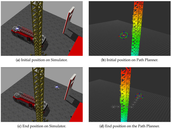
Figure 3.
Hexacopter navigation on a simulated environments with Static Collision Avoidance awareness, using Framework for Fully Autonomous UAVs (FFAU).
Another obstacle avoidance algorithm is presented in [57]. In this case, the vehicle is considered as a sphere, which simplifies the collision-free paths calculations and constructs a safety volume around it. Whenever an obstacle enters the safety volume, it constructs an ellipsoid volume around the obstacle and searches for a point that allows a free path. This is calculated from the current position to the escape point, ensuring no collisions through a defined distance from the escape point on the direction to the way-point. If no safe path is found, it increases the ellipse radius (a certain number of times) and performs another search. If no free path is found until a maximum ellipse radius, the UAV will alert the pilot and remain in the same position until the pilot takes control.
This method has the advantage of allowing an uninterrupted flight for avoiding the obstacle while having considerable low processing without a necessity to recalculate the trajectory considering arbitrary avoidance points.
Having this line of thought, Sabatini et al. [58] implemented an obstacle avoidance ellipsoid-shaped safety zone around obstacles, taking into account the UAV’s dynamics. For example, when the UAV is moving at high velocity and/or acceleration, the time to find an alternative path and the distance to the obstacle are the major inputs of the cost function, as they are the main parameters to be considered in critical situations.
3.2. Dynamic Collision Avoidance
To avoid a collision with a dynamic obstacle (such as an animal) or an incoming object (such as a thrown ball), a UAV needs to detect and execute a safe maneuver to avoid them. Perception latency is the time used to perceive the environment and process the captured data to generate control commands [59,60,61]. The higher the relative speed between the UAV and object, the more critical the role of perception latency becomes.
Compared to SCA algorithms, the DCA algorithms have not been much explored, which makes the task much harder. There are a few works such as the one from Poiesi and Cavallaro [62] where multiple image processing algorithms that estimate the time of collision of incoming objects are explored. The detection is accurate, but the algorithm takes approximately 10 seconds to process each frame (on an Intel i7-10750H Hexa-Core), making the solution not applicable in real-time scenarios. In addition, Faland et al. [63] delved into the event cameras to generate a computing efficient sensing pipeline that was capable of avoiding a ball thrown towards a quadcopter at speeds up to 9 m/s similar to the work done in [60]. However, these types of cameras are not common on commercial UAVs.
In this article, a novel solution that uses Deep Learning (DL) is proposed. In order to simplify the task, the problem was divided into three blocks. The first block is the Feature Extraction (FE), which utilizes a CNN to generate feature vectors for the video frames. The second block handles the video temporal information (stream) with RNNs and the input of multiple feature vectors. Finally, the third block receives the result of the last and uses a Feedforward Neural Network (FNN) to output a decision, which can be the collision detection or an escape trajectory. The proposed architecture is represented in Figure 4. These blocks will be further detailed in the following subsections. Implementations, visualization functions, and further information can be found at https://github.com/dario-pedro/uav-collision-avoidance/tree/master/train-models.
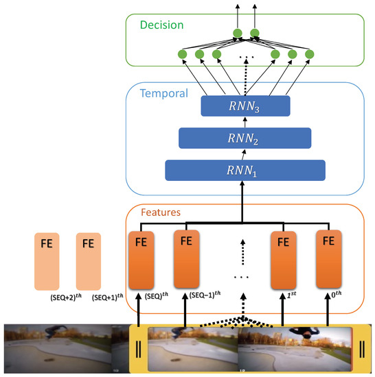
Figure 4.
Proposed dynamic collision avoidance neural networks architecture.
3.2.1. Feature Extraction
The FE is applied on each frame and generates a feature vector. For this, a CNN is used, namely a MobileNetV2 (MNV2) [64]. The architecture is based on an inverted residual structure where the input and output of the traditional residual block are thin bottleneck layers opposite to residual models that use expanded representations in the input and uses lightweight depth-wise convolutions to filter features in the middle expansion layer [64]. This model was selected because at the moment, it achieves the best trade-off between accuracy and computation for a low-power processor as the present in UAVs [64,65,66], achieving 72.8% top-1 accuracy on ImageNet with only 2.2 M parameters. The model receives a image and returns as output a matrix, which is converted into a 1280 feature vector by applying a 2D Global Average Pooling [67].
3.2.2. Temporal Correlation and Decision
The temporal correlation of the features data extracted from each frame is obtained by applying a RNN. In this paper, a 3-depth blocks Long Short Term Memory (LSTM) architecture is proposed, which receives a sequence of 25 input vectors, representing around 1 second of video at a 25 frame rate (the average video framerate of the selected dataset, the ColANet). The first layer has eight LSTMs, the second and the third has two LSTMs each. Both three layers are followed by dropout and batch normalization. Moreover, the last RNN layer is connected into a FNN with four neurons that are finally connected to two output neurons.
In a live scenario, the architecture is executed using a sliding window approach where the feature queue always contains the last 25 features vectors and is fed into the RNN. Whenever a new video frame is available, the frame is processed by the FE and the new feature vector is added to the features queue by shifting the previous values. Furthermore, the result of the RNN and FNN for a set of 25 feature vector array is the prediction for the last frame. Algorithm 1 presents the necessary sequential actions to process a new video frame, where it is assumed that all models have been previously loaded.
| Algorithm 1: Dynamic Collision Avoidance—processing the latest video frame. |
|
The processing is optimized when compared with solutions such as conv3d [68], which apply convolutions to a 3D space. In the proposed architecture, only the last frame needs to be processed by the CNN and introduced with a shift into a queue that is passed to the RNN. Afterward, the RNN and FNN are triggered, which will output a prediction.
3.2.3. Training and Results
To train the proposed architecture, the dataset ColANet (at https://colanet.qa.pdmfc.com/) was used [22], which contains around 100 videos that result to 18,872 images. This is a video dataset of collisions and has the possibility to output a classification target (collision or no collision) or a regression target. To simplify, in this paper the training and results are oriented to the classification problem. However, using the proposed architecture, working on the regression problem just requires the addition of four additional output neurons and target each output for an avoidance axis. The machine learning frameworks Tensorflow and Keras were used to facilitate the construction and training of such networks [69].
Initially, the MNV2 model was obtained using Tensorflow by using the transfer learning approach [70], with the weights pre-trained on the ImageNet dataset, which is a large dataset of 1.4 M images and 1000 classes of web images [71]. ImageNet has a fairly arbitrary research training dataset with categories like plane and eagle, but this base of knowledge helps in feature extraction tasks and the general world perception is transferred.
Firstly, the layer of MNV2 to be used for FE is chosen. The last classification layer (on “top”, like most diagrams of machine learning models go from bottom to top) is not useful. Instead, it is common practice to use the last layer before the flatten operation. This layer is called the “bottleneck layer”. Bottleneck features retain much generality as compared to the final/top layer. This can be done by loading a network that does not include the classification layers at the top, which is ideal for FE.
Afterward, all layers are frozen before compiling the model, which prevents weights from being updated during training. Then, a classification block is added, which is composed of a global average pooling 2D layer to convert the features to a single 1280-element vector per image, and a dense layer to convert these features into a single prediction per image. It is not necessary to add an activation function because this prediction will be treated as a raw prediction value. Positive numbers predict ‘collision’, negative numbers predict ‘no collision’. This last classification layer was trained to give some knowledge of the objective goal, using a binary cross-entropy loss and an Adam optimizer [72] with a learning rate and a decay rate. For the classification problem in study, the loss can be depicted as Equation (2),
where w refers to the model parameters (weights), N are the number of images, is the target label, and is the predicted label. The accuracy metric is given by Equation (3):
The training results of the added classifier is illustrated in the first 20 epochs of Figure 5 (before fine-tuning). At the end of the 20 epochs, using only single frames information, the model managed to predict collisions with 62.02% accuracy (validation accuracy). Afterward, a fine-tuned version of the MNV2 base model was trained. To do this, all layers were unfrozen. It is important to note that the first step is mandatory, because if a randomly initialized classifier is added on top of a pre-trained model and attempt to train all layers jointly, the magnitude of the gradient updates will be too large (due to the random weights from the classifier) and the pre-trained model will forget what it has learned (the transferred knowledge). The training results of the fine-tuned FE are the last 20 epochs of Figure 5 and achieved a final validation accuracy of 74.18%. On the last epochs, the difference between training and validation started to increase, which indicates the beginning of over-fitting, and for that reason, no further epochs were trained.
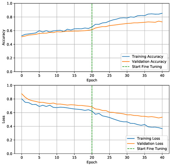
Figure 5.
Training Feature Extraction (FE) based on MobileNetV2 model. On the first 20 epochs, only output neurons are trained. Afterwards, the entire model is fine tuned.
The fine-tuning of the MNV2 network gives a model that is highly oriented to the collision classification problem. On one hand, this is good because it allows the CNN to prioritize some features, but on the other hand it is bad because it generalizes less (potentially leading to overfitting data), giving more importance to features present in the dataset. For this reason, the training of the RNN+FNN blocks will be presented in two versions. The first version uses the MNV2 with pre-trained weights from ImageNet. The second version uses the MNV2 with pre-trained weights from ImageNet and fine-tuned in the ColANet dataset.
Initially, the RNN+FNN blocks are trained with feature data from the CNN which has not been fine-tuned with ColANet data. In order to prepare the data for the second block, some constraints must be added:
- The input data must be an array of SEQ length. A value of 25 was considered in this paper, however any value between 20 and 50 yielded similar results;
- The generated sequences must only contain frames from a single video. To work with video data on GPUs is not a trivial task and generating video sequences adds an overhead. The dataset is seen by the model as a continuous stream of data, and this constrain must be enforced to avoid having the model learning jumps between videos (false knowledge);
- The last frame target label is the target for the entire sequence.
The Adam optimizer [72] with a learning rate and decay rate was used. The training result of the RNN with the FNN classification layer with the transferred FE weights and fine-tuned FE can be found at Figure 6 respectively.
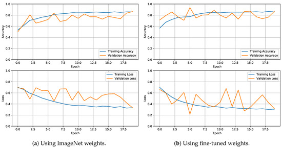
Figure 6.
Training evolution graph of the Dynamic Collision Avoidance (DCA) model with the FE.
The results of all the models are summarized in Table 1. It is possible to conclude that it is a valid approach for the DCA problem, but some additional developments and tests should be conducted. The image data trained CNN produced a score of accuracy on unseen data, whereas the RNN managed to use temporal features from an untrained MNV2 and reached an accuracy of above . This leads to the belief that temporal information has more importance in the collision avoidance problem, or even in any video related classification problem. Comparing the results on Table 1, it is concluded that the DCA model scores are quite similar. This suggests that in the worse case, the fine-tune of the MNV2 increased the values by pointing a worse RNN+FNN into the right direction, but on the top results when the key is generalization, it did not make much difference. The ColANet is a rather recent dataset and still has a low number of UAV collision videos (less than 100). This makes the training task harder due to the tendency of the model to overfit. As the number of available videos increases, the models will generalize better and produce better results.

Table 1.
Dynamic collision avoidance models’ comparison results.
The algorithm was deployed in a Jetson Nano on the DCA module of the proposed FFAU. The Jetson Nano managed to run the entire algorithm pipeline at an average of 182 ms, proving that it is a valid solution for SoA UAVs.
For the model to estimate the collision probability, instead of a classification problem, the last two neurons of the FNN would perform a regression for each axis.
4. Beyond Skyline
To integrate all UAVs in a platform, the Beyond Skyline platform was developed. It is a cloud-based platform that allows UAVs to be remote controlled. This platform has five main functionalities:
- Communication in real-time with the UAVs, receiving telemetry, video data, and transmitting commands;
- Actuate over these UAVs by uploading missions, with designated waypoints;
- Orchestrate a swarm missions with multiple UAVs;
- Collect and analyze data produced by several UAVs during each flight, with the possibility of replaying a given flight/mission;
- Parallel running computational heavy Artificial Intelligence (AI) algorithms facilitating user decisions.
The platform is the final piece of the overall architecture presented in Figure 2, which envisions a safe long distance control of multiple autonomous UAVs. This platform is composed by a BE, a relational database for non-temporal data (such as the UAV identities and users with permissions for that UAV), a time-series database for high rate temporal data (such as UAV flight telemetry), a Media-Gateway server for incoming video from the UAV, and finally a WA.
In the developed platform, the BE was developed in NestJS, the relational database in MySQL, the time-series database in InfluxDB, the Media-Gateway server using WebRTC, and the WA in Angular 8. The BE also implements service layers in order to simplify further integration with external APIs. All components are developed as docker images, which are then run in Kubernetes, making this approach easy to scale.
Whenever a UAV is switched on, it tries to establish a connection to the BE using websockets via 5G, WiFi, or 4G (by this order).
5. Field Tests Results
In order to fully demonstrate the safety and reliability features of the proposed framework, a custom hexacopter was developed, which was named Hexa Exterior Intelligent Flying Unit (HEIFU), and is illustrated in Figure 7. The hexacopter layout was chosen due to his inherent higher safety characteristics over the more common quadcopters. Hexacopters offer a significant advantage due to its six propellers. Even if one of those propellers fail, the other five can keep the UAV flying. This means that a motor failure does not mean the UAV will crash, damaging the equipment attached to it. Even if two propellers fail, although the UAV will not be able to fly, there is a chance that it remains stable enough to reach the ground safely.
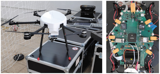
Figure 7.
Hexa Exterior Intelligent Flying Unit (HEIFU)—Custom developed hexacopter (left: Full shot of the UAV; right: Printed circuit board with the components).
The HEIFU weighs 6.5 kg with a battery and has an hovering time of around 35 min (without extra payload). It is composed of a PixHawk running Ardupilot, a Jetson Nano running Ubuntu 18.04 with ROS Melodic creating a bridge to Mavlink messages. Furthermore, a GPS-RTK Zed-F9P was integrated to enhance positioning, which provides 2 cm precision accuracy while under RTK corrections and 40 cm without. The positioning precision is of utter importance when the UAV is being controlled from a far distance (i.e., more than 4 km, when the pilot starts losing sight of the UAV). The modules presented in the previous sections are running in the Jetson Nano and the Communication Handler is capable of using WiFi, 3G, 4G, or 5G links within the UAV.
The communications performance between the UAV and platform was ascertained by analyzing the Round Trip Time (RTT). It was considered the time from the client on Beyond Skyline WA at the right side of Figure 8, to the UAV.
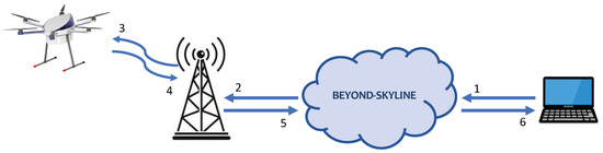
Figure 8.
Round trip time tests setup.
A complete RTT is the time it takes to complete the following six steps:
- The client, from the WA, sends a counter number and the name of the destination UAV for the RTT topic. The timestamp associated with this message is saved;
- The BE receives, analyzes the message structure and permissions, and sends this number to the UAV. Furthermore, a timestamp is added to the message;
- The UAV receives the message;
- The UAV re-sends a copy of the received message;
- The BE receives this message and sends it to all connected clients that have permission to receive information from this UAV. Additionally, it calculates the RTT between the server and UAV by using the timestamp registered in step 2;
- The server receives this message, verifies its value, creates a new timestamp from which it decreases the one saved in step (1) and calculates the RTT. It increments the counter and repeats from step (1).
The UAV flight capabilities were tested near Lisbon. The WA interface iterated over the RTT measurements in a vertical mission where the UAV took-off and went to 120 m altitude and then descended to the ground at 4 autonomously, starting a landing routine at 10 m with a descending speed of 1 . This was planned in the Beyond Skyline Mission Builder, which is illustrated in Figure 9. The UAV mission was repeated 15 times on the same day, with the WA controller running in different cities across the world. The summarized results are depicted in Table 2. The takeoff time of each flight was recorded and is presented in the second column of the table. Moreover, the average RTT () and standard deviation are presented for the different links. The table is sorted by the and it is composed of nine columns, which are the location where the user was located, the time the autonomous mission started, the total , the UAV-BE, BE-WA, the total BE-WA, UAV-BE, BE-WA, and the 99th percentile.
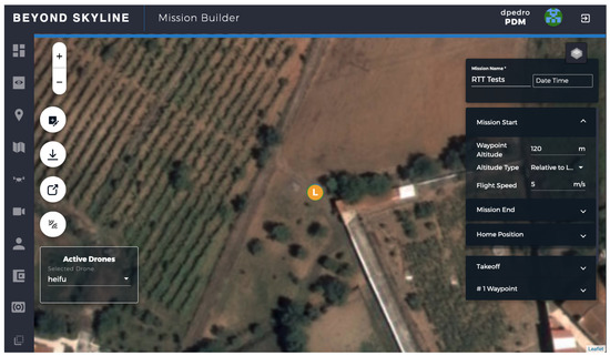
Figure 9.
Round Trip Time (RTT) tests missions planning on the Beyond Skyline web-interface.
Table 2.
RTT between the UAV and the Beyond Skyline platform analyzed by varying the web application location.
Discussion of Results
The common link on the tests was the connection between the UAV and BE. The RTT was stable on this link, varying between ≈61 and 80 ms. The difference is in the link between the BE and WA. When the user was closer to the BE facilities, the RTT was ≈13 ms (from Lisbon), and when it was approximately 18,000 km away, it took ≈352 ms (from Sydney). In aviation, the maximum RTT delay from a flying handling perspective is of approximately 300 ms [73]. Wang et al. tested the latency influence on pilots [74] and suggest that with up to 360 ms of delay the task can be accomplished.
By looking at the results on Table 2, it is also possible to conclude that connectivity is a key factor in the performance of the visualization part. In Portugal, four tests were performed from different locations. Lisbon and Caparica were the closest locations to the server and achieved similar results to Porto, which is in the north of the country. Additionally, Beja and Porto are approximately the same distance from the test site, and Porto presented better performance. Figure 10a presents the RTT readings in relation to the UAV altitude relative to the takeoff. The X-axis presents approximated intervals of altitude using the data from the test realized with the WA in Lisbon. A RTT measurement request was done every 250 ms, but the number of measurements varies with the environment conditions (the wind might affect the speed of the UAV).
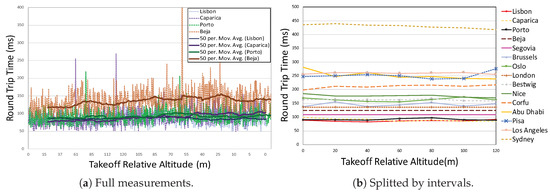
Figure 10.
RTT in function of the UAV take off relative altitude.
In Figure 10 it is possible to observe the variation of RTT measurements with the UAV relative altitude. It is possible to conclude that on the test location the relative altitude does not have a clear correlation with the RTT, presenting a similar performance on any altitude. Table 3 presents the conditional by the altitude intervals Lisbon test, where this conclusion is also possible to verify. The same analyses were performed for all tests, obtaining similar results. An airborne communication relay was tested in [75], and also presented no variability latency from 5 to 15 m.
Table 3.
Variation of round trip time in function of the UAV relative altitude by intervals, using the Lisbon measurements data.
The graph of Figure 11 illustrates the RTT Cumulative Distribution Function (CDF). Most of the tests present similar curves, with the exception of Corfu and Pisa, where there was a higher RTT variance. From the UAV control point of view, reliable low latency is more important than the average delay. The UAV control algorithms have to be designed to tolerate a delay that is defined by the maximum delay in the channel and fit the Ultra Reliable Low Latency Communications (URLLC) requirements [76]. In this paper, the 99% percentile is considered as a measurement of the URLLC performance of the measured channels. In Figure 11 it is also possible to conclude that the connectivity on the WA side is more important than the distance itself. The 99th percentile is lower in Sydney than in Pisa.
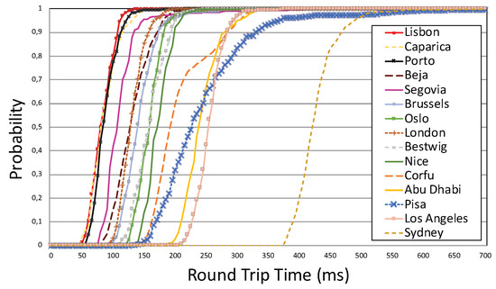
Figure 11.
RTT Cumulative Distribution Functions (CDF).
As far as the authors know these are innovative test results and there is no similar analysis that can be directly compared. Nevertheless, some related works correlations are discussed. A 4G remote control of a ground vehicle between antipodes was tested in [77], but no quantitative results were displayed and the tests indicate around a 1 s delay and the necessity of Secure Socket Shell (SSH) tunnels. In [78] a cloud-based application for UAVs was developed and tested, which indicates the proposed FFAU is scalable. If no cellular communication is available, it is also possible to use the WiMax connectivity [79].
Finally, it is presented a heat map on Figure 12. The colleagues doing the test were asked to pilot the UAV from the application and asserted that it felt like a real-time experience, and they could do it without difficulties.
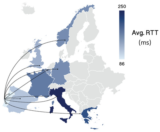
Figure 12.
Average RTT in the tested of countries in Europe.
The collision avoidance algorithms have also been tested, but no significant data has been saved for quantitative analysis. In future, the authors will work on this topic, perform additional tests, and identify some metrics that will allow comparison with algorithms in literature.
6. Conclusions and Future Work
In this work, a framework for fully autonomous UAVs was proposed. The authors believe that safety and reliability are the two key factors for UAVs’ autonomous navigation. Thus, the collision avoidance problem was explored in depth and a novel solution for dynamic obstacle avoidance, composed of DNNs blocks was proposed, showing a high accuracy on the classification problem using the ColANet dataset. In this article, the first version of the proposed module was developed, targeting the collision classification task. The network was presented in a way that is simple to adapt to the escape vectors regression task.
All the modules presented in the framework for remote and fully autonomous UAVs were developed and integrated in a custom hexacopter, connected to a cloud-based platform, named Beyond Skyline. The proposed architecture enabled remote control of UAVs via Internet, in a portable, extensible, open-source platform that manages containerized workloads and services, which facilitated scalability, configuration, and automation. The actions were sent thought the platform, while safety was enforced by the FFAU, providing constant feedback and telemetry to the pilot, which could take control of the autonomous UAV when desired.
A communication testbed was developed and the framework was tested by receiving the UAV telemetry from different locations around the world, registering connectivity metrics. The results proved that with a standard Internet connection, it is possible to pilot or manage UAVs remotely, regardless of the location. Moreover, with the proposed framework, sending missions to the UAVs was safe and allowed real-time monitoring.
This work will be continued with further developments on the modules presented in this paper. As guidelines for future work, the list below enumerates some of the main topics that will provide novel contributions:
- Optimized DCA. The DCA module can be explored in greater depth, as this area still have many unsolved problems. The dataset must be amplified and the proposed algorithm needs to be optimized to run faster. The concept can be optimized by exploring different features extractors, variations on the sequence size with which the RNN is ran and different types of RNN;
- Testing the DCA algorithm on real UAVs in autonomous missions;
- Edge multi-tenant computing. Whenever a UAV is flying in a different country, the BE and WebRTC server should be instantiated in the proximity, minimizing the RTT, providing better control of the UAVs;
- Framework modules variants. Different implementations of the proposed framework should be developed, allowing a performance evaluation and comparison.
Author Contributions
Conceptualization, D.P.; Funding acquisition, L.M.C.; Investigation, D.P., J.P.M.-C., F.A., R.S.-M., L.B. and A.M.; Resources, L.M.C.; Software, D.P., J.P.M.-C., F.A. and R.S.-M.; Supervision, L.C., J.M.F. and A.M.; Validation, D.P., J.P.M.-C., L.B. and L.C.; Writing—original draft, D.P. and J.P.M.-C.; Writing—review & editing, D.P., J.P.M.-C., F.A., R.S.-M., L.B., L.C., J.M.F. and A.M. All authors have read and agreed to the published version of the manuscript.
Funding
This work is supported by the European Regional Development
Fund (FEDER), through the Regional Operational Programme of Lisbon (POR
LISBOA 2020) and the Competitiveness and Internationalization
Operational Programme (COMPETE 2020) of the Portugal 2020 framework
[Project 5G with Nr. 024539 (POCI-01-0247-FEDER-024539)]. This project
has also received funding from the ECSEL Joint Undertaking (JU) under
grant agreement No 783221. The JU receives support from the European
Union’s Horizon 2020 research and innovation programme and Austria,
Belgium, Czech Republic, Finland, Germany, Greece, Italy, Latvia,
Norway, Poland, Portugal, Spain, Sweden. This work was also supported by
Portuguese Agency “Fundação para a Ciência e a Tecnologia” (FCT), in the
framework of project UIDB/00066/2020.
Acknowledgments
The authors would like to thank the Beyond Vision Research Group and PDMFC Research and Development Team. Furthermore, the authors would like to thank a set of colleagues that helped testing the platform from different points around the world, namely India, Kike, Didier, Diogo, Vale, Kate, Miguel, Haris, Rita, André, Gonçalo, Max and Oz.
Conflicts of Interest
The authors declare no conflict of interest.
References
- Patias, P. Introduction to Unmanned Aircraft Systems. Photogramm. Eng. Remote. Sens. 2016, 82, 89–92. [Google Scholar] [CrossRef]
- Koubaa, A.; Qureshi, B.; Sriti, M.F.; Javed, Y.; Tovar, E. A service-oriented Cloud-based management system for the Internet-of-Drones. In Proceedings of the 2017 IEEE International Conference on Autonomous Robot Systems and Competitions, ICARSC 2017, Coimbra, Portugal, 26–28 April 2017. [Google Scholar] [CrossRef]
- Alvarez-Vanhard, E.; Houet, T.; Mony, C.; Lecoq, L.; Corpetti, T. Can UAVs fill the gap between in situ surveys and satellites for habitat mapping? Remote Sens. Environ. 2020, 243, 111780. [Google Scholar] [CrossRef]
- Navarro, A.; Young, M.; Allan, B.; Carnell, P.; Macreadie, P.; Ierodiaconou, D. The application of Unmanned Aerial Vehicles (UAVs) to estimate above-ground biomass of mangrove ecosystems. Remote Sens. Environ. 2020, 242, 111747. [Google Scholar] [CrossRef]
- Shakhatreh, H.; Sawalmeh, A.H.; Al-Fuqaha, A.; Dou, Z.; Almaita, E.; Khalil, I.; Othman, N.S.; Khreishah, A.; Guizani, M. Unmanned Aerial Vehicles (UAVs): A Survey on Civil Applications and Key Research Challenges. IEEE Access 2019, 7, 48572–48634. [Google Scholar] [CrossRef]
- Weibel, R.E.; Hansman, R.J. Safety Considerations for Operation of Unmanned Aerial Vehicles in the National Airspace System; MIT International Center for Air Transportation: Cambridge, UK, 2005. [Google Scholar]
- Zhong, Y.; Hu, X.; Luo, C.; Wang, X.; Zhao, J.; Zhang, L. WHU-Hi: UAV-borne hyperspdectral with high spatial resolution (H2) benchmark datasets and classifier for precise crop identification based on deep convolutional neural network with CRF. Remote Sens. Environ. 2020, 250, 112012. [Google Scholar] [CrossRef]
- Meinen, B.U.; Robinson, D.T. Mapping erosion and deposition in an agricultural landscape: Optimization of UAV image acquisition schemes for SfM-MVS. Remote Sens. Environ. 2020, 239, 111666. [Google Scholar] [CrossRef]
- Bhardwaj, A.; Sam, L.; Akanksha; Martín-Torres, F.J.; Kumar, R. UAVs as remote sensing platform in glaciology: Present applications and future prospects. Remote Sens. Environ. 2016, 175, 196–204. [Google Scholar] [CrossRef]
- Yao, H.; Qin, R.; Chen, X. Unmanned Aerial Vehicle for Remote Sensing Applications—A Review. Remote Sens. 2019, 11, 1443. [Google Scholar] [CrossRef]
- Gerhards, M.; Schlerf, M.; Mallick, K.; Udelhoven, T. Challenges and Future Perspectives of Multi-/Hyperspectral Thermal Infrared Remote Sensing for Crop Water-Stress Detection: A Review. Remote Sens. 2019, 11, 1240. [Google Scholar] [CrossRef]
- Messina, G.; Modica, G. Applications of UAV thermal imagery in precision agriculture: State of the art and future research outlook. Remote Sens. 2020, 12, 1491. [Google Scholar] [CrossRef]
- Gaffey, C.; Bhardwaj, A. Applications of unmanned aerial vehicles in cryosphere: Latest advances and prospects. Remote Sens. 2020, 12, 948. [Google Scholar] [CrossRef]
- Rödel, C.; Stadler, S.; Meschtscherjakov, A.; Tscheligi, M. Towards autonomous cars: The effect of autonomy levels on Acceptance and User Experience. In Proceedings of the Automotive UI 2014—6th International Conference on Automotive User Interfaces and Interactive Vehicular Applications, in Cooperation with ACM SIGCHI, Seattle, WA, USA, 17–19 September 2014. [Google Scholar] [CrossRef]
- Caron, C. After Drone Hits Plane in Canada, New Fears About Air Safety. 2017. Available online: https://www.nytimes.com/2017/10/17/world/canada/canada-drone-plane.html (accessed on 19 May 2019).
- BBC. Drone’ Hits British Airways Plane Approaching Heathrow Airport. 2016. Available online: https://www.bbc.com/news/uk-36067591 (accessed on 19 May 2019).
- Canada, C. Drone That Struck Plane Near Quebec City Airport Was Breaking the Rules|CBC News. 2017. Available online: http://www.cbc.ca/news/canada/montreal/garneau-airport-drone-quebec-1.4355792 (accessed on 19 May 2019).
- BBC. Drone Collides with Commercial Aeroplane in Canada. 2017. Available online: https://www.bbc.com/news/technology-41635518 (accessed on 19 May 2019).
- Goglia, J. NTSB Finds Drone Pilot at Fault for Midair Collision with Army Helicopter. 2017. Available online: https://www.forbes.com/sites/johngoglia/2017/12/14/ntsb-finds-drone-pilot-at-fault-for-midair-collision-with-army-helicopter/ (accessed on 19 May 2019).
- Rawlinson, K. Drone Hits Plane at Heathrow Airport, Says Pilot. 2016. Available online: https://www.theguardian.com/uk-news/2016/apr/17/drone-plane-heathrow-airport-british-airways (accessed on 19 May 2019).
- Tellman, J.; News, T.V. First-Ever Recorded dRone-Hot Air Balloon Collision Prompts Safety Conversation. 2018. Available online: https://www.postregister.com/news/local/first-ever-recorded-drone-hot-air-balloon-collision-prompts-safety/article_7cc41c24-6025-5aa6-b6dd-6d1ea5e85961.html (accessed on 19 May 2019).
- Pedro, D.; Mora, A.; Carvalho, J.; Azevedo, F.; Fonseca, J. ColANet: A UAV Collision Avoidance Dataset. In Technological Innovation for Life Improvement; Springer: Cham, Switzerland, 2020. [Google Scholar]
- Gharibi, M.; Boutaba, R.; Waslander, S.L. Internet of Drones. IEEE Access 2016, 4, 1148–1162. [Google Scholar] [CrossRef]
- Apvrille, L.; Tanzi, T.; Dugelay, J.L. Autonomous drones for assisting rescue services within the context of natural disasters. In Proceedings of the 2014 31th URSI General Assembly and Scientific Symposium, URSI GASS 2014, Beijing, China, 16–23 August 2014. [Google Scholar] [CrossRef]
- Mahmoud, S.; Mohamed, N. Collaborative UAVs cloud. In Proceedings of the 2014 International Conference on Unmanned Aircraft Systems, ICUAS 2014, Orlando, FL, USA, 27–30 May 2014. [Google Scholar] [CrossRef]
- Mahmoud, S.; Mohamed, N. Broker architecture for collaborative UAVs cloud computing. In Proceedings of the 2015 International Conference on Collaboration Technologies and Systems, CTS 2015, Atlanta, GA, USA, 1–5 June 2015. [Google Scholar] [CrossRef]
- Mahmoud, S.; Mohamed, N.; Al-Jaroodi, J. Integrating UAVs into the Cloud Using the Concept of the Web of Things. J. Robot. 2015, 2015, 631420. [Google Scholar] [CrossRef]
- Introduction. 2005. Available online: https://mavlink.io/en/ (accessed on 19 May 2019).
- ROS. Powering the World’s Robots. 2007. Available online: https://www.ros.org/ (accessed on 19 May 2019).
- La, H.J.; Kim, S.D. A service-based approach to designing cyber physical systems. In Proceedings of the 9th IEEE/ACIS International Conference on Computer and Information Science, ICIS 2010, Yamagata, Japan, 18–20 August 2010. [Google Scholar] [CrossRef]
- Combe, T.; Martin, A.; Di Pietro, R. To Docker or Not to Docker: A Security Perspective. IEEE Cloud Comput. 2016, 3, 54–62. [Google Scholar] [CrossRef]
- Cloud Native Computing Foundation. What Is Kubernetes—Kubernetes. 2019. Available online: https://kubernetes.io/docs/concepts/overview/what-is-kubernetes/ (accessed on 27 October 2020).
- Acuña, P.; Acuña, P. Kubernetes. In Deploying Rails with Docker, Kubernetes and ECS; Apress: New York, NY, USA, 2016. [Google Scholar] [CrossRef]
- Bowman, J.; Mihelich, P. Camera Calibration—ROS Wiki. 2014. Available online: http://wiki.ros.org/camera_calibration (accessed on 27 October 2020).
- Kalman, R.E. A New Approach to Linear Filtering and Prediction Problems. Trans. ASME-Basic Eng. 1960, 82, 35–45. [Google Scholar] [CrossRef]
- Turner, D.; Lucieer, A.; Watson, C. An automated technique for generating georectified mosaics from ultra-high resolution Unmanned Aerial Vehicle (UAV) imagery, based on Structure from Motion (SFM) point clouds. Remote Sens. 2012, 4, 1392. [Google Scholar] [CrossRef]
- Keselman, L.; Woodfill, J.I.; Grunnet-Jepsen, A.; Bhowmik, A. Intel(R) RealSense(TM) Stereoscopic Depth Cameras. In Proceedings of the IEEE Computer Society Conference on Computer Vision and Pattern Recognition Workshops, Honolulu, HI, USA, 21–26 July 2017. [Google Scholar] [CrossRef]
- Galceran, E.; Carreras, M. A survey on coverage path planning for robotics. Robot. Auton. Syst. 2013, 61, 1258–1276. [Google Scholar] [CrossRef]
- Hert, S.; Tiwari, S.; Lumelsky, V. A terrain-covering algorithm for an AUV. Auton. Robot. 1996, 3, 91–119. [Google Scholar] [CrossRef]
- Azevedo, F.; Oliveira, A.; Dias, A.; Almeida, J.; Moreira, M.; Santos, T.; Ferreira, A.; Martins, A.; Silva, E. Collision avoidance for safe structure inspection with multirotor UAV. In Proceedings of the 2017 European Conference on Mobile Robots, ECMR 2017, Paris, France, 6–8 September 2017. [Google Scholar] [CrossRef]
- Paul, S.; Paul, S. Real-Time Transport Protocol (RTP). In Multicasting on the Internet and Its Applications; Springer: Boston, MA, USA, 1998. [Google Scholar] [CrossRef]
- Marr, D. Visual information processing: The structure and creation of visual representations. Philos. Trans. R. Soc. Lond. Ser. B Biol. Sci. 1980, 290, 199–218. [Google Scholar] [CrossRef]
- Kuchar, J.K.; Yang, L.C. A Review of Conflict Detection and Resolution Modeling Methods. IEEE Trans. Intell. Transp. Syst. 2000, 1, 179–189. [Google Scholar] [CrossRef]
- Kovacs, L. Visual Monocular Obstacle Avoidance for Small Unmanned Vehicles. In Proceedings of the IEEE Computer Society Conference on Computer Vision and Pattern Recognition Workshops, Las Vegas, NV, USA, 26 June–1 July 2016. [Google Scholar] [CrossRef]
- Hrabar, S. An evaluation of stereo and laser-based range sensing for rotorcraft unmanned aerial vehicle obstacle avoidance. J. Field Robot. 2012, 29, 215–239. [Google Scholar] [CrossRef]
- Merz, T.; Kendoul, F. Beyond visual range obstacle avoidance and infrastructure inspection by an autonomous helicopter. In Proceedings of the IEEE International Conference on Intelligent Robots and Systems, San Francisco, CA, USA, 25–30 September 2011. [Google Scholar] [CrossRef]
- Hrabar, S. 3D path planning and stereo-based obstacle avoidance for rotorcraft UAVs. In Proceedings of the 2008 IEEE/RSJ International Conference on Intelligent Robots and Systems, IROS, Nice, France, 22–26 September 2008. [Google Scholar] [CrossRef]
- Magree, D.; Mooney, J.G.; Johnson, E.N. Monocular visual mapping for obstacle avoidance on UAVs. J. Intell. Robot. Syst. Theory Appl. 2014, 74, 17–26. [Google Scholar] [CrossRef]
- Yang, Z.; Gao, F.; Shen, S. Real-time monocular dense mapping on aerial robots using visual-inertial fusion. In Proceedings of the IEEE International Conference on Robotics and Automation, Singapore, 29 May–3 June 2017. [Google Scholar] [CrossRef]
- Li, C.J.; Ling, H. Synthetic aperture radar imaging using a small consumer drone. In Proceedings of the IEEE Antennas and Propagation Society, AP-S International Symposium (Digest), Vancouver, BC, Canada, 19 July 2015. [Google Scholar] [CrossRef]
- Hornung, A.; Wurm, K.M.; Bennewitz, M.; Stachniss, C.; Burgard, W. OctoMap: An efficient probabilistic 3D mapping framework based on octrees. Auton. Robot. 2013, 34, 189–206. [Google Scholar] [CrossRef]
- Hermann, A.; Drews, F.; Bauer, J.; Klemm, S.; Roennau, A.; Dillmann, R. Unified GPU voxel collision detection for mobile manipulation planning. In Proceedings of the 2014 IEEE/RSJ International Conference on Intelligent Robots and Systems, Chicago, IL, USA, 14–18 September 2014; pp. 4154–4160. [Google Scholar]
- Burgard, W.; Bennewitz, M.; Tipaldi, D.; Spinello, L. Introduction to Mobile Robotics: Techniques for 3D Mapping. 2019. Available online: http://ais.informatik.uni-freiburg.de/teaching/ss14/robotics/slides/17-3dmapping.pdf (accessed on 19 May 2019).
- Koenig, N.; Howard, A. Design and use paradigms for Gazebo, an open-source multi-robot simulator. In Proceedings of the 2004 IEEE/RSJ International Conference on Intelligent Robots and Systems (IROS), Sendai, Japan, 28 September–2 October 2004. [Google Scholar] [CrossRef]
- Kavraki, L.E.; Svestka, P.; Latombe, J.; Overmars, M.H. Probabilistic roadmaps for path planning in high-dimensional configuration spaces. IEEE Trans. Robot. Autom. 1996, 12, 566–580. [Google Scholar] [CrossRef]
- Lavalle, S.M. Rapidly-Exploring Random Trees: A New Tool for Path Planning; Technical Report; Computer Science Department, Iowa State University: Ames, IA, USA, 1998. [Google Scholar]
- Hrabar, S. Reactive obstacle avoidance for rotorcraft UAVs. In Proceedings of the IEEE International Conference on Intelligent Robots and Systems, San Francisco, CA, USA, 25–30 September 2011. [Google Scholar] [CrossRef]
- Sabatini, R.; Gardi, A.; Richardson, M.A. LIDAR Obstacle Warning and Avoidance System for Unmanned Aircraft. Int. J. Mech. Aerosp. Ind. Mechatronics Eng. 2014, 8, 718–729. [Google Scholar]
- Gallup, D.; Frahm, J.M.; Mordohai, P.; Pollefeys, M. Variable baseline/resolution stereo. In Proceedings of the 26th IEEE Conference on Computer Vision and Pattern Recognition, CVPR, Anchorage, AK, USA, 23–28 June 2008. [Google Scholar] [CrossRef]
- Mueggler, E.; Forster, C.; Baumli, N.; Gallego, G.; Scaramuzza, D. Lifetime estimation of events from Dynamic Vision Sensors. In Proceedings of the IEEE International Conference on Robotics and Automation, Seattle, WA, USA, 26–30 May 2015. [Google Scholar] [CrossRef]
- Andrew, A.M. Multiple View Geometry in Computer Vision; Cambridge University Press: Cambridge, UK, 2001. [Google Scholar] [CrossRef]
- Poiesi, F.; Cavallaro, A. Detection of fast incoming objects with a moving camera. In Proceedings of the British Machine Vision Conference, London, UK, 4–7 September 2017. [Google Scholar] [CrossRef]
- Falanga, D.; Kim, S.; Scaramuzza, D. How Fast Is Too Fast? the Role of Perception Latency in High-Speed Sense and Avoid. IEEE Robot. Autom. Lett. 2019, 4, 1884–1891. [Google Scholar] [CrossRef]
- Sandler, M.; Howard, A.; Zhu, M.; Zhmoginov, A.; Chen, L.C. MobileNetV2: Inverted Residuals and Linear Bottlenecks. In Proceedings of the IEEE Computer Society Conference on Computer Vision and Pattern Recognition, Salt Lake City, UT, USA, 18–22 June 2018. [Google Scholar] [CrossRef]
- Ma, N.; Zhang, X.; Zheng, H.T.; Sun, J. ShuffleNet V2: Practical Guidelines for Efficient CNN Architecture Design. In Proceedings of the The European Conference on Computer Vision (ECCV), Munich, Germany, 8–14 September 2018. [Google Scholar]
- Howard, A.G.; Zhu, M.; Chen, B.; Kalenichenko, D.; Wang, W.; Weyand, T.; Andreetto, M.; Adam, H. MobileNets: Efficient Convolutional Neural Networks for Mobile Vision Applications. arXiv 2017, arXiv:1704.04861. [Google Scholar]
- Boureau, Y.L.; Ponce, J.; Lecun, Y. A theoretical analysis of feature pooling in visual recognition. In Proceedings of the ICML 2010—27th International Conference on Machine Learning, Haifa, Israel, 21–24 June 2010. [Google Scholar]
- Tran, D.; Bourdev, L.; Fergus, R.; Torresani, L.; Paluri, M. Learning spatiotemporal features with 3D convolutional networks. In Proceedings of the IEEE International Conference on Computer Vision, Santiago, Chile, 7–13 December 2015. [Google Scholar] [CrossRef]
- Shanmugamani, R. Deep Learning for Computer Vision: Expert Techniques to Train Advanced Neural Networks Using TensorFlow and Keras; Packt Publishing Ltd.: Birmingham, UK, 2018. [Google Scholar] [CrossRef]
- Pan, S.J.; Yang, Q. A survey on transfer learning. IEEE Trans. Knowl. Data Eng. 2010, 22, 1345–1359. [Google Scholar] [CrossRef]
- Russakovsky, O.; Deng, J.; Su, H.; Krause, J.; Satheesh, S.; Ma, S.; Huang, Z.; Karpathy, A.; Khosla, A.; Bernstein, M.; et al. ImageNet Large Scale Visual Recognition Challenge. Int. J. Comput. Vis. 2015, 115, 211–252. [Google Scholar] [CrossRef]
- Kingma, D.P.; Ba, J.L. Adam: A method for stochastic optimization. In Proceedings of the 3rd International Conference on Learning Representations, ICLR 2015—Conference Track Proceedings, San Diego, CA, USA, 7–9 May 2015. [Google Scholar]
- de Vries, S.C. UAVs and Control Delays; TNO Rep.; TNO: The Hague, The Netherlands, 2005. [Google Scholar]
- Wang, F.; Qi, S.; Li, J. An Analysis of Time-delay for Remote Piloted Vehicle. MATEC Web Conf. 2017, 114, 04012. [Google Scholar] [CrossRef]
- Guo, W.; Devine, C.; Wang, S. Performance analysis of micro unmanned airborne communication relays for cellular networks. In Proceedings of the 2014 9th International Symposium on Communication Systems, Networks and Digital Signal Processing, CSNDSP 2014, Manchester, UK, 23–25 July 2014. [Google Scholar] [CrossRef]
- Popovski, P.; Stefanovic, C.; Nielsen, J.J.; de Carvalho, E.; Angjelichinoski, M.; Trillingsgaard, K.F.; Bana, A.S. Wireless Access in Ultra-Reliable Low-Latency Communication (URLLC). IEEE Trans. Commun. 2019, 67, 5783–5801. [Google Scholar] [CrossRef]
- Burke, P.J. 4G Antipode: Remote Control of a Ground Vehicle From Around the World. IEEE J. Miniaturization Air Space Syst. 2020. early access. [Google Scholar] [CrossRef]
- Itkin, M.; Kim, M.; Park, Y. Development of cloud-based UAV monitoring and management system. Sensors 2016, 16, 1913. [Google Scholar] [CrossRef] [PubMed]
- Dusza, B.; Wietfeld, C. Performance evaluation of IEEE 802.16e mobile WiMAX for long distance control of UAV swarms. In Proceedings of the 2010 IEEE International Conference on Wireless Information Technology and Systems, ICWITS 2010, Honolulu, HI, USA, 28 August–3 September 2010. [Google Scholar] [CrossRef]


Publisher’s Note: MDPI stays neutral with regard to jurisdictional claims in published maps and institutional affiliations. |
© 2020 by the authors. Licensee MDPI, Basel, Switzerland. This article is an open access article distributed under the terms and conditions of the Creative Commons Attribution (CC BY) license (http://creativecommons.org/licenses/by/4.0/).