Article

Design Study for the Construction of Turbo Roundabouts under Constrained Site Conditions

by
Alicja Sołowczuk
* and
Stanisław Majer
Department of Roads and Bridges, West Pomeranian University of Technology in Szczecin, 71-311 Szczecin, Poland
*
Author to whom correspondence should be addressed.
Sustainability 2023, 15(17), 13220; https://doi.org/10.3390/su151713220
Submission received: 31 July 2023 / Revised: 28 August 2023 / Accepted: 31 August 2023 / Published: 3 September 2023

Abstract

:
Turbo-roundabouts are one of the most frequently recommended road junction design options when it comes to increasing traffic capacity and traffic safety. This is in particular true of suburban areas, with dominant traffic flow on the main road and moderate traffic flow on the side road. Other intersections handling local traffic and considerably constricting the availability of space are usually located in the vicinity of such intersections. Another factor contributing to the limited availability of land for construction in these locations is the presence of surrounding residential housing. Then, choosing the suitable turbo-roundabout type becomes the main issue. The article presents a case study for the selection of a type of turbo roundabout under the conditions of considerably constricted land availability based on the analysis of the provision of a swept path for the chosen design vehicles. The article considers the standard egg-type turbo-roundabouts, “look-a-like” type turbo-roundabouts, non-standard “flattened” turbo-roundabouts and ellipse-based roundabouts, with non-standard geometries of the truck apron and central island. For each of the analysed roundabout types, setting-out methods were described in detail, allowing the designer to quickly select a type of roundabout suitable for the specific constrained site conditions. This article analyses the applicability of non-standard turbo roundabouts for three area types: LUDA low urbanisation degree area, BA built-up area and CDA highly commercially developed area along the side road, wherever standard roundabouts are not practicable due to constraints imposed by existing buildings, canals or any other obstacles found at the project site.

1. Introduction

The recent years have seen a remarkable growth in the use of motor vehicles in many countries as a consequence of their on-going economic growth, posing the challenge of how to ensure the required capacity of road junctions without compromising traffic safety. Turbo roundabouts are considered a solution to this problem by offering a higher traffic handling capacity as compared to conventional junctions [1,2]. Their main benefits include [1,2,3,4,5,6,7,8]:
A higher capacity by 150–250%, as compared to conventional single- or even double-lane roundabouts. They are also superior to the signalised junctions by eliminating waiting time at traffic lights.
Traffic safety improvement by eliminating traffic conflicts and intersecting flows in particular. Worth noting is the reduction of fatalities or injuries by approximately 70% as compared to right-of-way intersections and by approximately 50% as compared to signalised intersections or conventional two-lane roundabouts. In addition, turbo-roundabouts reduce the total number of road incidents by 85% and rear-end collisions by 95%.
Land takes a comparable approach to double-lane approach and exit signalised intersections, accommodating the simultaneous movement of two tractor-trailer units in any direction during one signal cycle.
Lower future maintenance costs and lower environmental and social costs of the project compared to signalised intersections, with only a slightly higher project cost.
There are four standard turbo-roundabout designs, as described in [3,9,10]: basic, egg, knee and rotor. Turbo roundabouts are typically designed where a busy major road crosses a secondary local road. In these situations, an egg turbo-roundabout is the recommended design option [1,3,4,5]. In suburban locations, the biggest engineering challenge is the limited availability of land. In the case of small egg turbo-roundabouts, scarcity of land or close proximity of intersections on the approach legs may pose a challenge to designing a proper, standard turbo-roundabout. Locations on the outskirts or near downtown areas aggravate the problem due to the constraints caused by the existing road network. When looking for a solution to increase capacity and ensure road safety, the designer must also consider the vehicle-swept path requirement. This is not uncommon in engineer’s practice; one will not find in the literature turbo roundabout layout and design guidelines for situations where only some of the design principles detailed in [1] and given in the web portal of Dirk de Baan [10] may be satisfied. Examples of successfully completed standard turbo roundabouts despite various local constraints are shown in the following figures: Figure 1—homes or valuable sacral buildings located in close proximity, Figure 2—presence of natural obstacles such as lakes or canals. Figure 3, in turn, shows a non-standard “flattened” turbo-roundabout in an area with site constraints, including apartment buildings located on the outskirts and large public buildings.
Four design principles have been developed for standard turbo-roundabouts [1,10] (based on Dirk de Baan’s web portal [10]):
Vehicles that are about to enter the roundabout through any leg are not obliged to give way to the vehicles navigating through the roundabout on any of the two traffic lanes of the roundabout carriageway.
Having to give way to vehicles riding on all the three traffic lanes of the roundabout carriageway is complicated and impracticable for many road users. For this reason, larger turbo-roundabouts should be provided with traffic lights as an additional traffic control measure.
A raised curb installed in the separation lane allocates a specific lane for each vehicle, which shall not change while navigating through the roundabout. There are no traffic conflicts due to weaving or crossing. Turbine roundabouts do not allow driving in circles from any direction.
Vehicles are gradually shifted from the inside to the outside, following spiral paths without any crossing movements. The smooth path of travel between the raised kerb separation lanes allows driving through the roundabout at a maximum speed of 35 to 40 km/h.
Dirk de Baan provides two more design principles for standard turbo roundabouts, including a separation lane featuring a raised concrete kerb (based on Dirk de Baan’s web portal [10]):
Dual-lane exits should be provided on the main legs to maximise the roundabout capacity. However, in the case of moderate straight-through traffic, a single exit lane may suffice.
At each leg, a road user riding in the outer lane must have the option to exit or continue navigating through the turbo-roundabout. A road user driving in the inner lane will have this choice in the next segment.
The above-mentioned Dutch standard turbo-roundabout design principles have been mostly departed from by Prof. Tollazzi et al. [12,13,14,15] and in the article of Ciampo et al. [7] in the case of non-standard turbo-roundabouts described by them. The departures concern the shape of the turbo roundabout, “flattened” along the side legs axes (Figure 3), an irregular truck apron shape and a different central island shape (e.g., a standard circle, ellipse or other).
Another departure from the above-mentioned Dutch guidelines are elliptical turbine roundabouts with a layout based on the theory of ellipses, as described by Prof. Grabowski [16]. In his article [16], Prof. Grabowski describes how to lay out an elliptical turbo roundabout recommended for crossings between roads carrying considerably different traffic volumes, in particular where most traffic is handled by the main road. In the conclusions of the described analysis, Prof. Grabowski [16] recommends “flattening” the roundabout shape along the side road axis in proportion to the magnitude of this traffic volume difference. However, there are no definite guidelines for the relationship between these two parameters. That said, in analyses where swept path is considered a design requirement, it appears to take precedence over any requirement resulting from the as-yet indefinite flattening/ volume difference relationship.
Yet another issue is maximising the junction capacity in constrained areas by choosing the appropriate turbo roundabout type. The capacity traffic capacity issue problem has been dealt with by a number of researchers [2,13,17,18,19,20,21,22,23]. They adopted various hypotheses and simulation models with the purpose of calibrating the already existing methods and adjusting them for various analyses, with the overall objective of demonstrating the superiority of turbo roundabouts over standard roundabouts in terms of traffic handling capacity. Some authors point to the importance of full equilibrium traffic allocation among the approach legs and sometimes also the traffic lanes, e.g., [7,22,23]. Others considered varied traffic flow scenarios for turning movements and analysed the effect of this variation on the final capacity. A different approach was taken in the articles [7,8], where traffic flow variation on the main road depending on the effect of adjacent crossings was considered alongside different traffic flow scenarios on the lanes and movements on the roundabout approach legs. The main factors considered in the capacity analyses were: driving behaviour, gap acceptance distribution, delay suffered by the road users about to enter, loss of time, queue length, etc. There are also a few articles dealing with the capacity of roundabouts “flattened” along the side leg axes [7,14,15,22]. These studies showed that with a smaller traffic volume on the main approach legs, standard turbo-roundabouts offered, in all cases, a higher capacity than conventional ones. Gallelli and Vaiana [24] demonstrated the relevance of the traffic composition of the respective movements, which should be considered in traffic capacity analyses alongside approach leg traffic volumes and different traffic flow allocation scenarios. Additionally, interesting in this context is the article by Liu et al. [6], in which four- and five-leg turbo-roundabouts were superimposed on the existing large multi-lane conventional roundabout Lujiazui in Shanghai. In this case study, in situ measurements of different traffic flow scenarios were used to investigate the effect of the roundabout diameter, which varied from 30 m to 80 m for both layouts under analysis, along with the total incoming traffic volume and traffic allocation as the factors relevant to the turbo roundabout capacity. Additionally, the relationship between the above-mentioned design parameters, traffic volume and flow allocation on the roundabout legs, on the one hand, and the accident potential and traffic safety indicators, on the other hand, was analysed.
The above literature review allowed us to pinpoint a gap in the currently available design guidelines and studies that do not provide roundabout design guidelines maximising the capacity and traffic safety for situations where standard turbo roundabouts are not practicable due to size constraints imposed by existing buildings, canals or other obstacles found at the project site. These issues are addressed in this article. The adopted method of analysis is presented in the diagram (Figure 4). Section 2 uses a case study to characterise the chosen intersection area and gives the parameters of the design vehicles applied in the swept path analysis. The adopted research method, including the pre-determined determinants, is also presented in this section. Section 3 presents proposed layouts of the analysed turbo roundabouts of different types and selected fragments of the conducted swept path analysis. It also describes turbo blocks, defining the layout of the selected turbo roundabouts. Section 4 defines the primary determinants for facilitating the selection of the most adequate turbo roundabout type and presents a discussion of the swept path analysis results obtained for six turbo roundabouts differing in terms of land take. Pros and cons are given for each roundabout type based on the adopted determinants. Section 5 provides the design guidelines for the respective turbo roundabout types, depending on the site constraints.

2. Materials and Methods
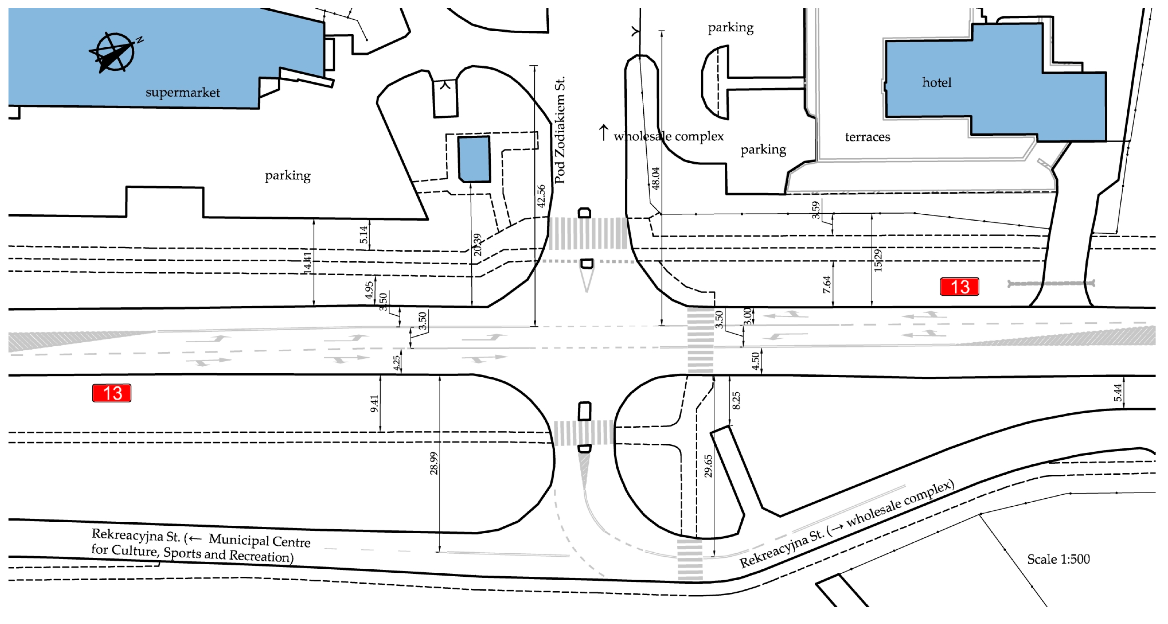
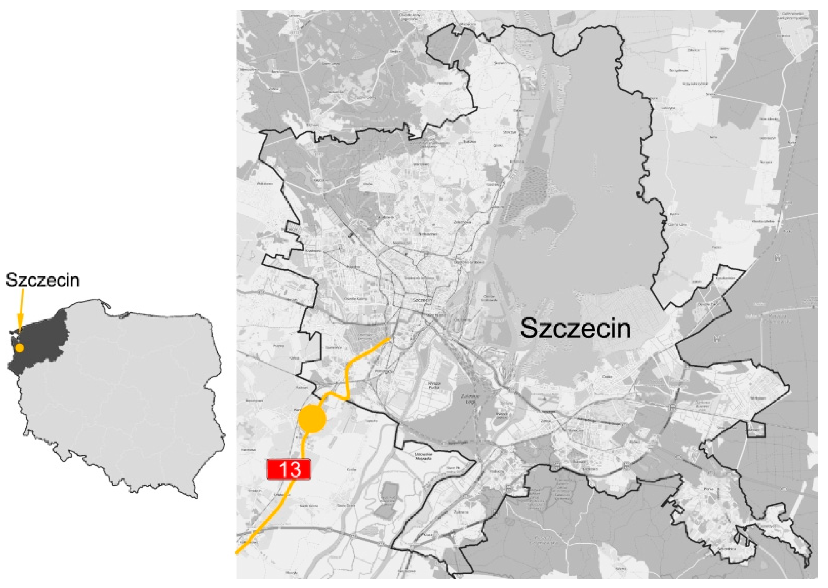
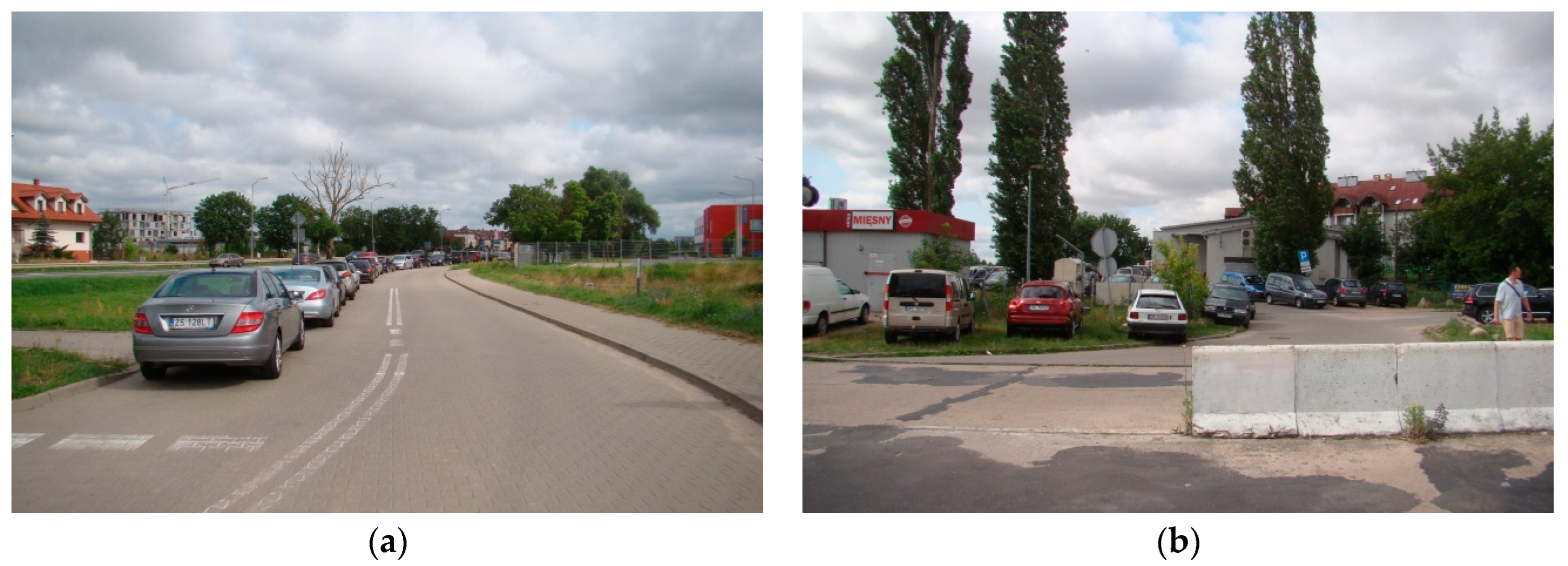
2.1. Study Area

The site chosen for the case study concerning turbo roundabout type selection for constrained project sites was a junction between the DK13 national road and a local street located in the suburbs of Szczecin, Poland (Figure 5). The layout plan of the junction under analysis is given in Figure A1 in Appendix A.
The streets intersected by DK13 serve as neighbourhood driveways. However, they are also used by articulated trucks serving the Biedronka supermarket and large and busy warehouses located nearby. The side streets are ca. 6 m wide, single, two-lane carriageways, widened to ca. 12 m just before the entrance to the warehouse to accommodate ticket gates. Additionally, DK13 is a single two-lane carriageway with additional left-turn lanes at the existing junctions. The DK13 carriageway is ca. 10.70 m wide. DK13 includes a foot and cycle path on the west side of the section along the residential area. On the east side of DK13 runs only a footpath, the same as along Rekreacyjna side street. Therefore, it was necessary to provide pedestrian and cycle crossings in the turbo roundabouts to be designed as part of this study. On the west side, the nearest exits that limit land availability are located ca. 37 m from the DK13 centreline. To the east runs Rekreacyjna St., which serves mostly as a driveway carrying heavy traffic to rapidly expanding warehouses. It runs approximately 32 m from the DK13 centreline.
A high heavy traffic volume was noted on the turn movements of the junction, including mainly articulated trucks delivering goods to the supermarket and warehouses. A traffic count cartogram based on data provided in [26] and our own traffic count data is shown in Figure A2 in Appendix B. Illustrative hourly traffic volumes are given in Table A1 in Appendix B. Figure A3 and Figure A4 in Appendix C, in turn, show the junction traffic growth charts for years 2010, 2023 and 2043, the last defining the junction upgrading project timespan. The biggest traffic flow challenge is the growing volume of heavy traffic on DK13, with a remarkable increase in the number of turning vehicles heading to the nearby warehouses. This resulted in the formation of queues on the side approach legs, which was the primary reason for choosing a turbo roundabout in place of the current junction.
Parking spaces are also in great need, as currently customers visiting the supermarket and warehouses park on the local street or choose illegal parking sites entered through the pedestrian crossing (Figure 6). The benefits of the turbo roundabout project include higher capacity than offered by the existing channelised junction, elimination of queues on the side approach legs and traffic safety improvements.

2.2. Design Vehicles and Swept Path

Based on data reported in [26] and our own traffic count data, the authors chose the following design vehicles (DV) for the swept path analysis: articulated truck DV1 semi-trailer and DV2 municipal service vehicles. The main DV parameters are given in Table 1. According to observations made during local visions, DV1 should be provided with a swept path for traffic from any approach leg, while DV2 swept path was required only for the Rekreacyjna St. leg from the south, leading to the Municipal Centre for Culture, Sports and Recreation in Przecław. The combined DV1 and passenger car swept paths vehicles and passenger cars should be checked for right-turn movements from the main road only in the case of wide entry or exit from the main road for the purpose of determining the mountable apron surface area and the appropriate road surface marking layout.

2.3. Standard Turbo Roundabout in a Constrained Site

The design process of a standard turbo roundabout should start with choosing the roundabout design type and size. Based on the guidelines of [1,28] a small roundabout with the smallest diameter defined by the outer edge of the roundabout carriageway at 45.18 m should be pre-selected for the suburban location and traffic volume of the junction under analysis. In the case under analysis, the traffic volumes on the main and side legs (see Appendix B and Appendix C) suggests selection of egg roundabout having one entry and one exit lane on the side approach legs.
Therefore, a standard turbo roundabout should be an option of choice, with the input design parameters adopted in compliance with the guidelines of [1], summarised in Appendix D (Table A2). As the first step of the analysis, a small Egg turbo roundabout was designed. In Poland, the special concrete kerbs separating the truck apron from the roundabout carriageway are elevated to just 3–4 cm above the surface and this height was used in the analyses. Yet another departure from the Dutch guidelines [1] was to allow the trucks to go onto the truck apron, in compliance with [28].
Figure 7 shows the roundabout drawn on an ortophotomap background, to demonstrate impracticability of a standard turbo roundabout with two entry lanes (Figure 7a) and non-standard turbo roundabout with one exit lane (Figure 7b) on the DK13 main road approach legs. In the first case, a 0.7 m wide raised separation lane width was used, (consisting of two pavement marking lines and a 0.30 m wide raised concrete curb), a design in line with the Dutch guidelines [1]. In the second case a narrower separation lane was used, of the width defined by the marking lines width.
Concerning the limited availability of land narrow separation lane (Figure 8) recommendation of [28] solely the 0.24 m wide separation lane was considered in further analyses. In Poland, narrow separation lanes are used on “look-a-like” turbo roundabouts, composed of line markings (Figure 8a) or raised U-25 recycled rubber featuring a reflective tape adhered to both sides, mechanically fixed to the pavement in the line markings area (Figure 8d). Therefore, whenever the term “separation lane” appears in the further part of this article, it shall mean the above-mentioned U-25 traffic separator located on the horizontal line marking (Figure 8d), thus avoiding repeated detailed descriptions.
The land take analysis showed that an egg turbo-roundabout would not fit within the project site, despite adopting the minimum design parameters. In addition, a splitter island, not to mention the required pedestrian/ cycle crossing, would not fit on the eastern side leg due to the supermarket exit and the hotel parking located there. At the eastern leg, the availability of land is effectively limited by the service road running there.
The DV1 swept path analysis for the supermarket exit showed impracticability of this movement, should an Egg roundabout be designed there (Figure 7). Similar conclusions can be drawn with regard to the second side approach leg on the east side and the Rekreacyjna St. junction, where a splitter island and pedestrian crossing are not practicable. The geometrical analysis of the two turbo-roundabouts shown in Figure 7 showed that with one exit lane on the main approach leg and the traffic separation feature limited to the U-25 separator placed on the line marking (Figure 7b) it would not be possible to design a proper turb- roundabout. This is because the maximum spacing of the side splitter islands, measured along the side legs had decreased to just ca. 0.5 m. One exit lane would reduce the land take only along the main road legs (Figure 7b). This being so, the authors conducted a case study later in the article and proposed the following non-standard turbo-roundabouts with one or two traffic lanes on the main approach legs:
  • “flattened” egg turbo-roundabouts,
  • elliptical turbo-roundabouts with a central island shape typically for a turbo-roundabout,
  • elliptical turbo roundabouts with an elliptical central island.

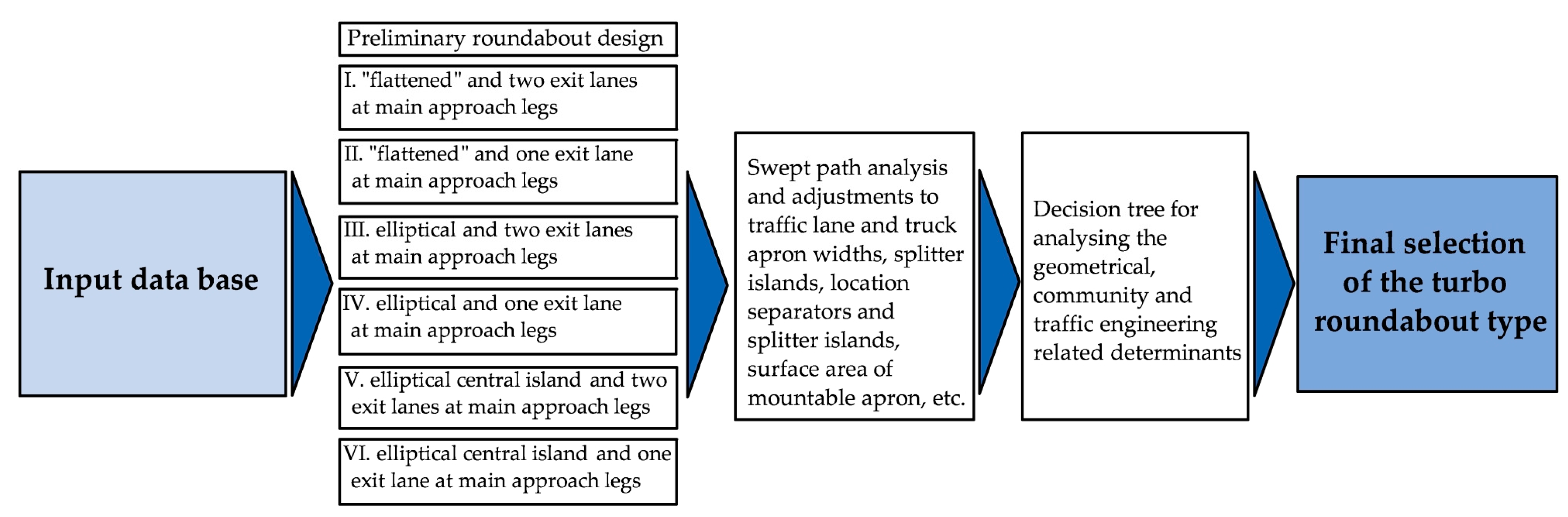
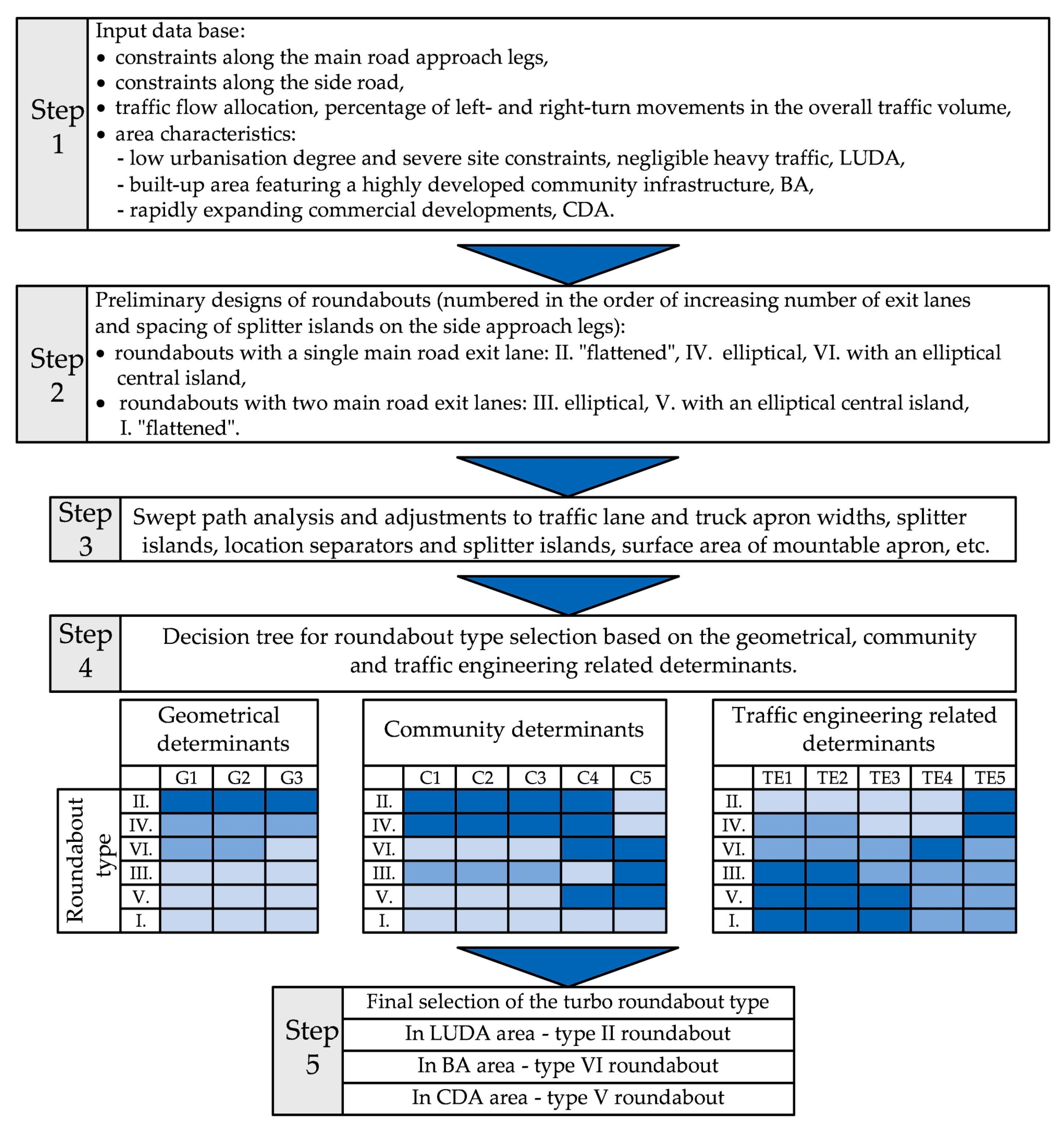
2.4. Non-Standard Turbo-Roundabout Selection Method for Constrained Areas

The first step of the constrained site analysis was to define the input requirements and pre-design different roundabout types, considering the swept path requirement. For this purpose, the method of selecting the appropriate roundabout type in a given location has been developed, as schematically represented in Figure 9. Figure 9 provides also the numbering and naming of the pre-selected roundabouts.
The following conditions were initially included in the input database:
constraints located sideways on the main road, having a determining effect on the limitation of the number of exit lanes on the main road approach legs to one,
distance of the existing side road constraints, measured along the side road from the main road centreline, having a determining effect on the practicable design of vehicle turn movements and splitter island design (i.e., length and type: nontraversable or traversable),
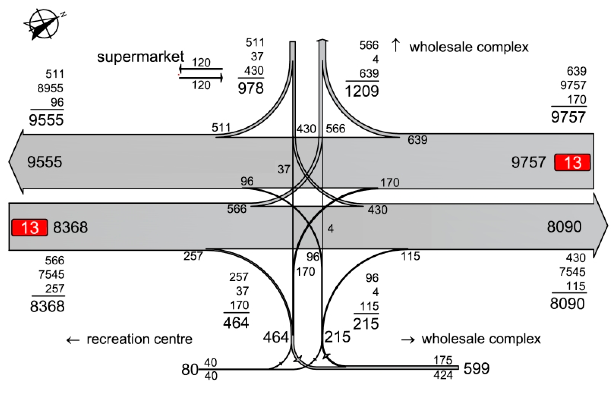
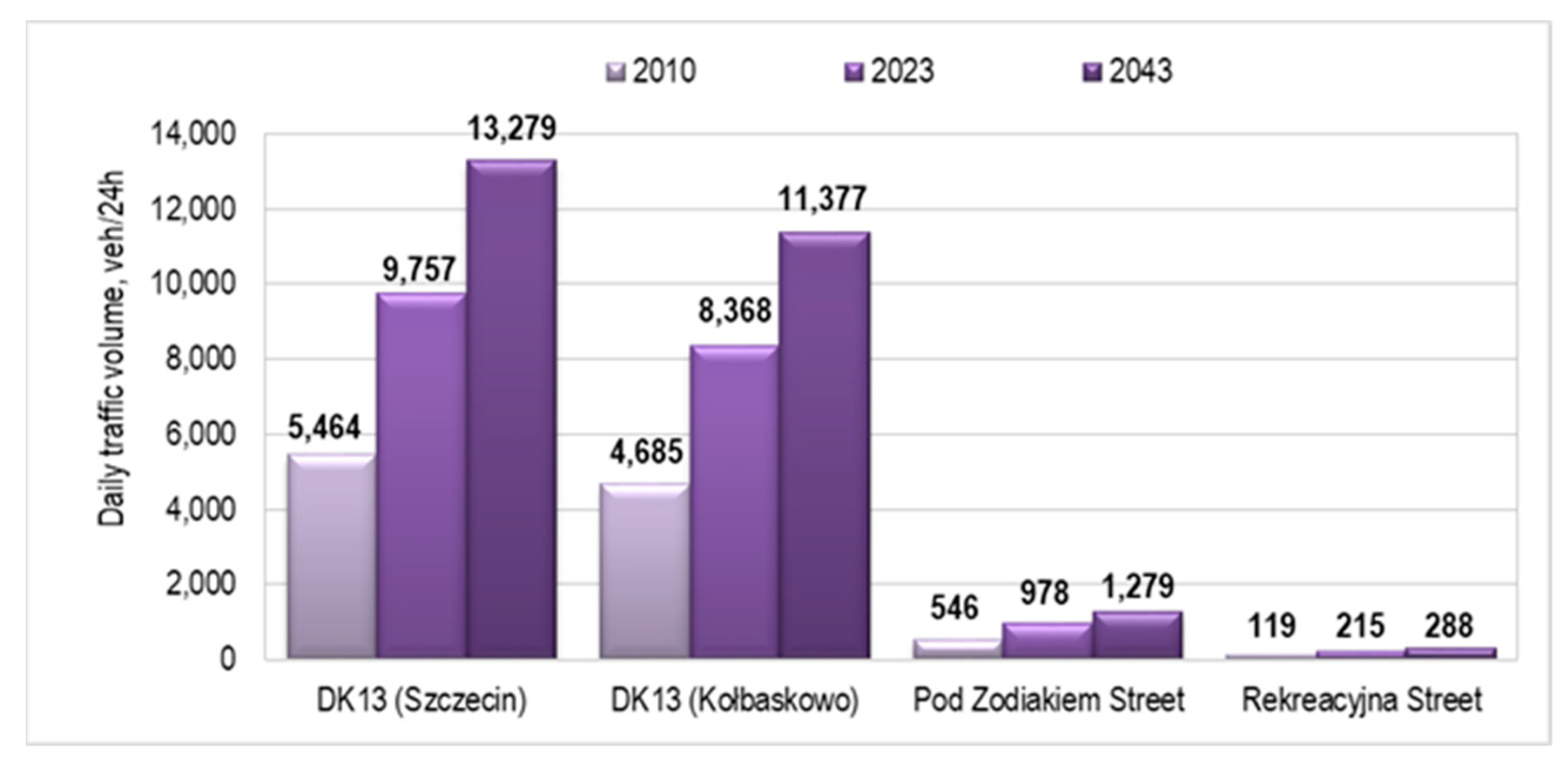
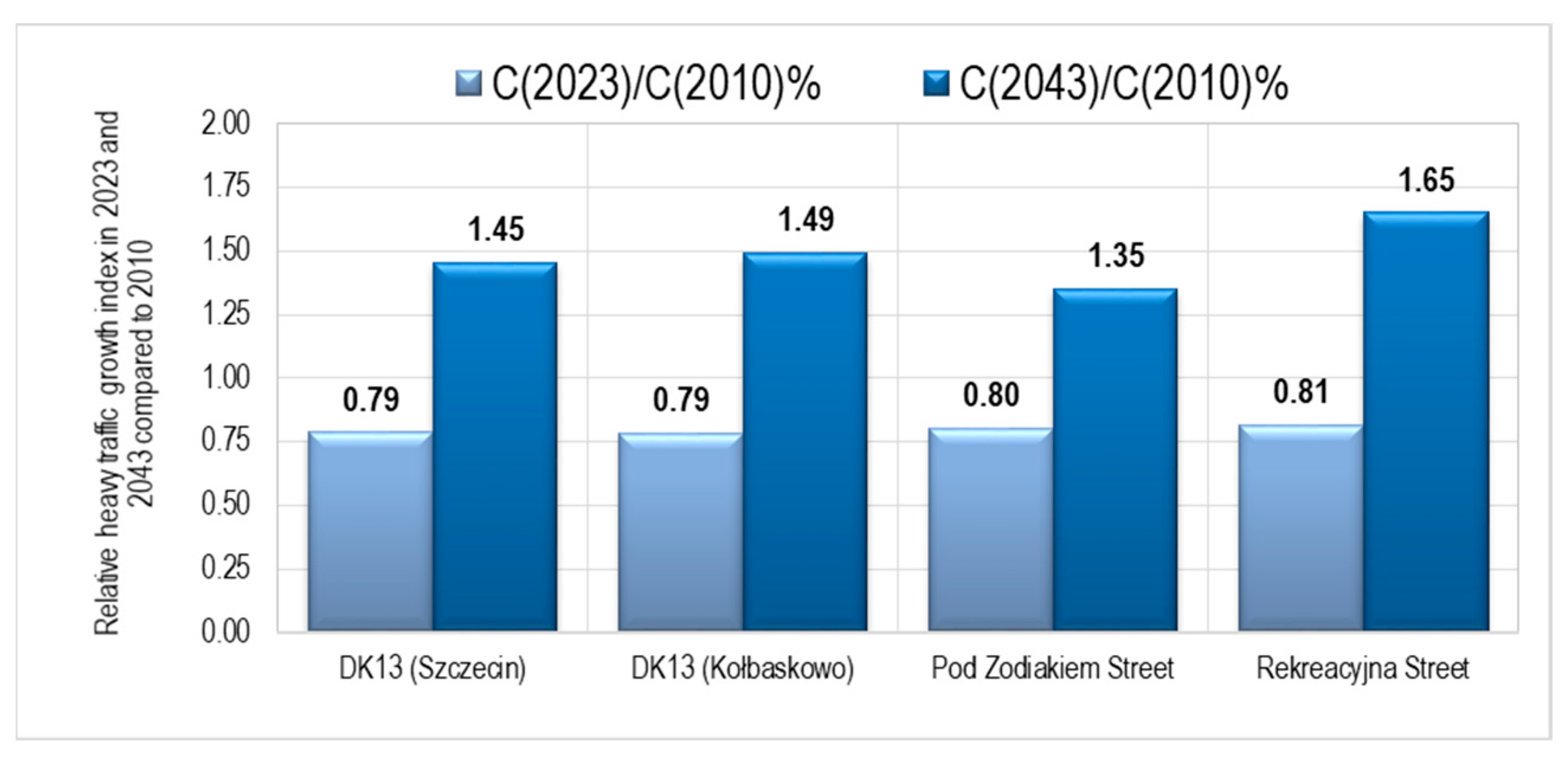
total current and projected traffic volumes, traffic flow allocation on both roads and traffic composition indicating the expected heavy traffic volume on the turn movements of the analysed legs,
type of developments around the planned roundabout location.
The identified determinants were to be refined following the analyses of the roundabout geometry, swept paths and mountable apron requirements. The final, defined determinants are described in detail in Section 4.

3. Results

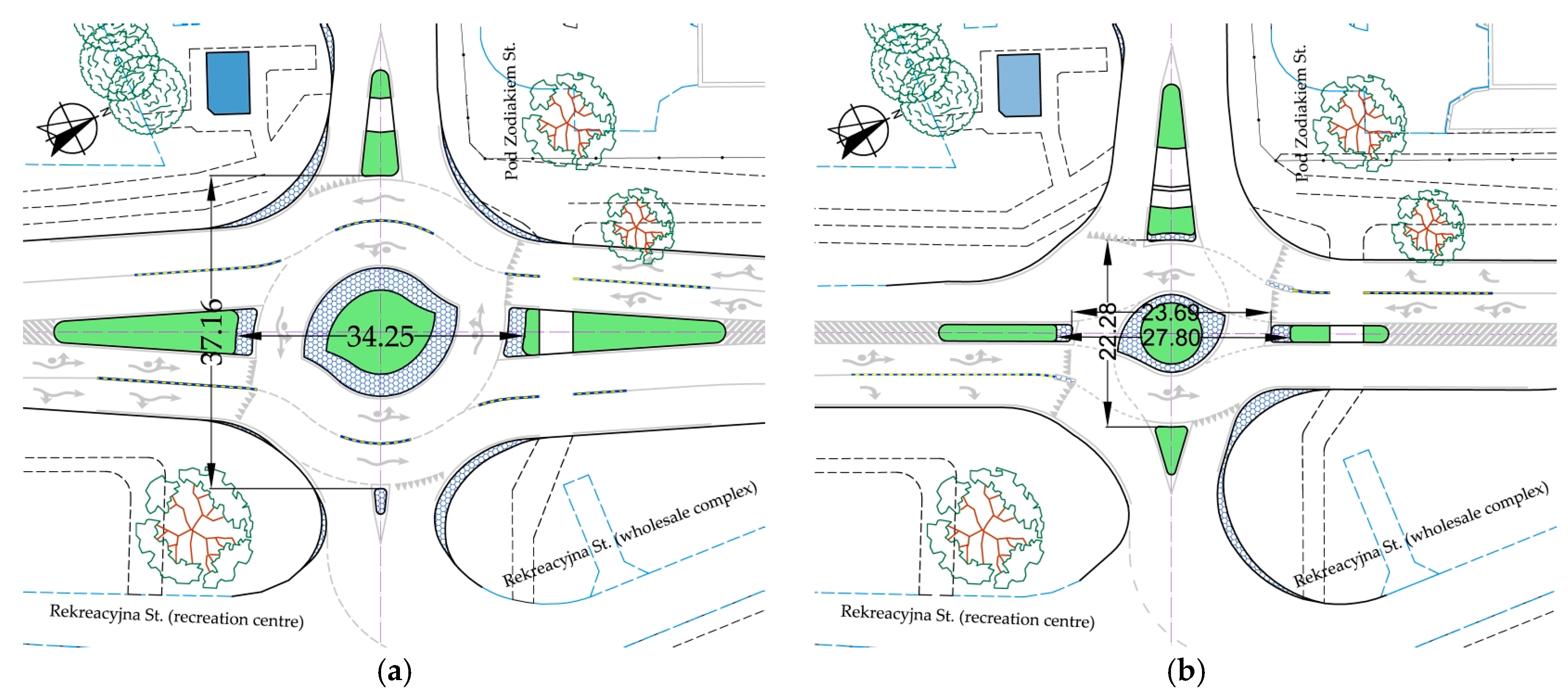
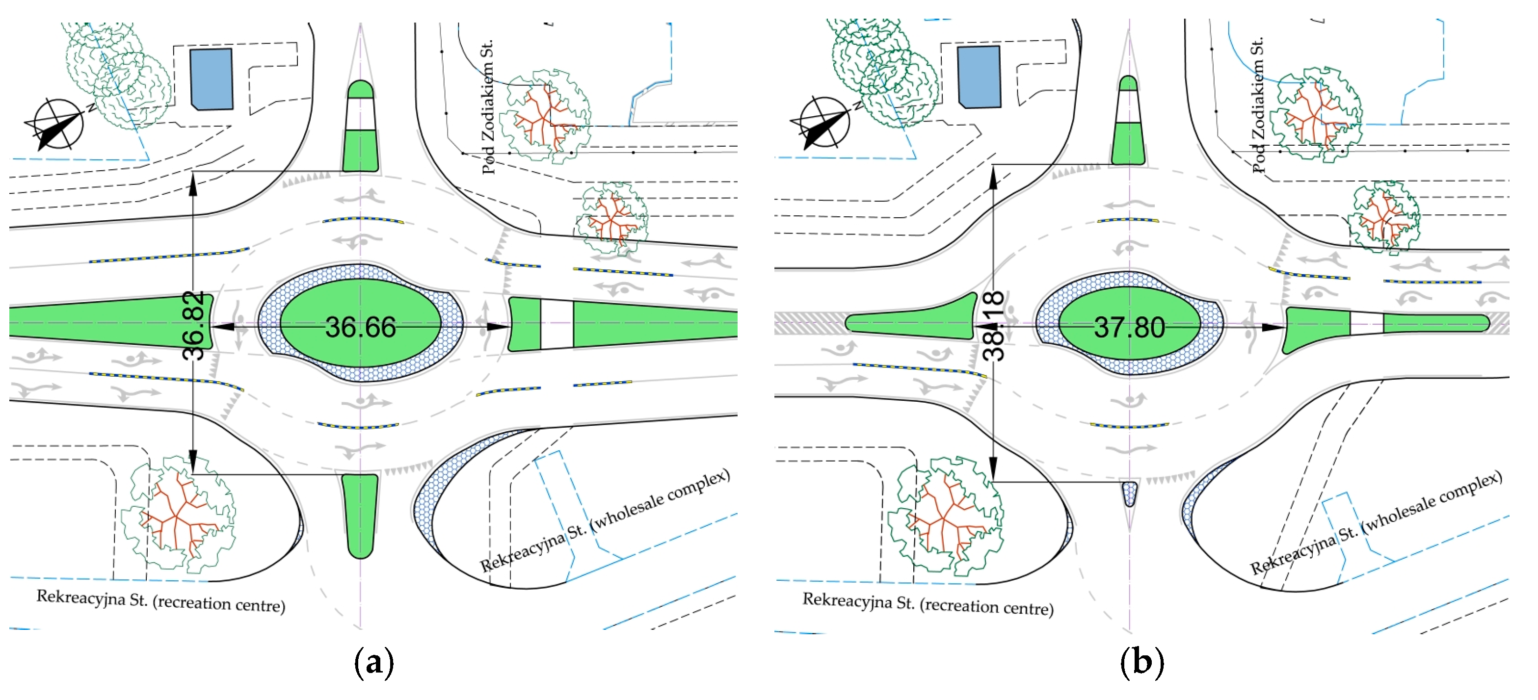
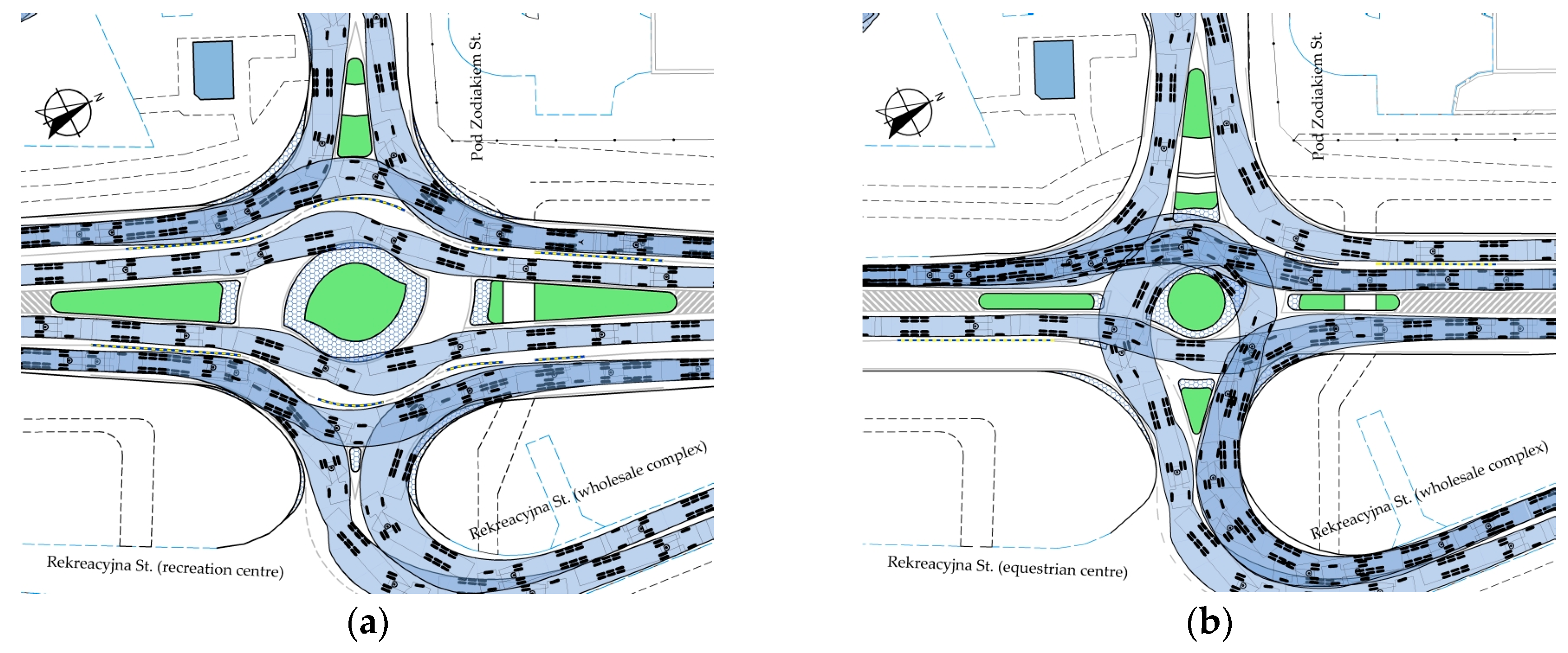
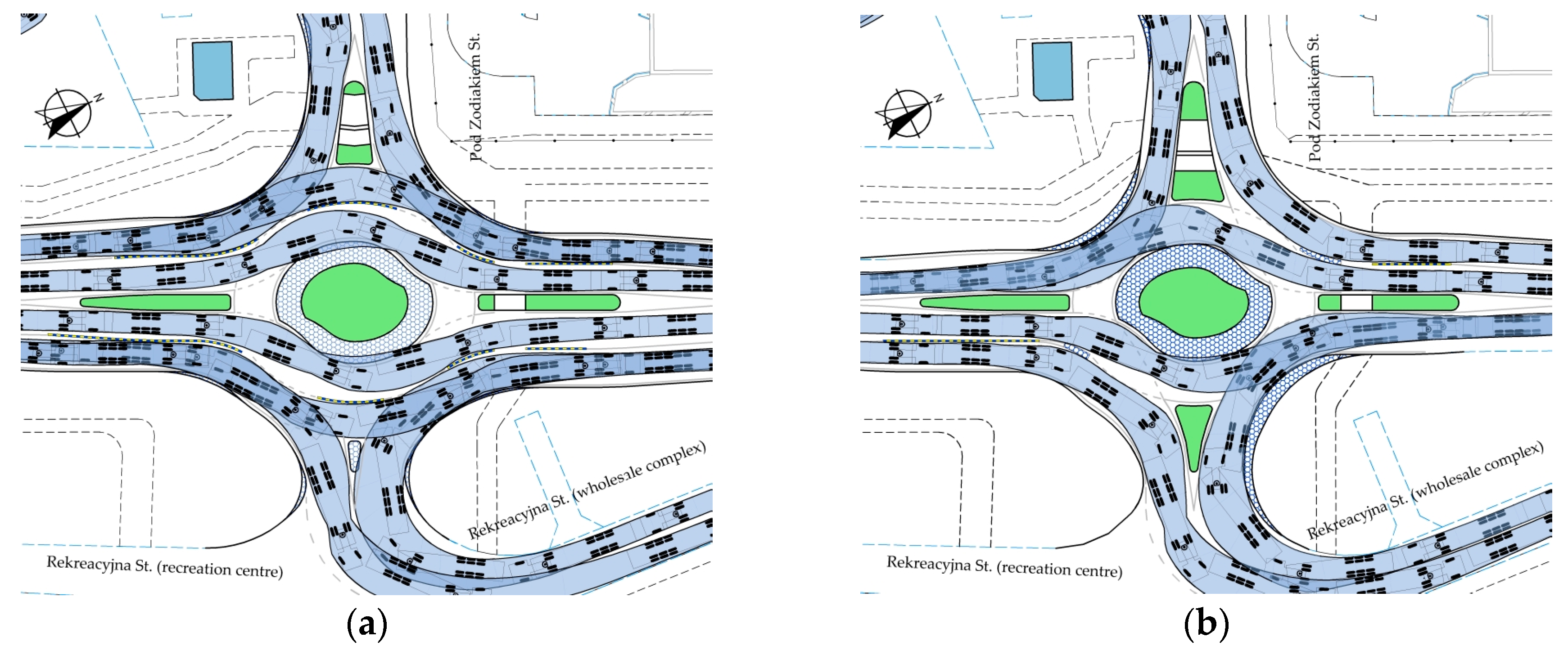
3.1. “Flattened” Turbo-Roundabout Featuring a 0.24-m-Wide Separation Lane

Only “flattened” shape turbo-roundabouts were considered in the case under analysis, as standard turbo-roundabouts were precluded by the existing land constraints. These preselected roundabouts could have one or two traffic lanes on the main approach legs, as appropriate to the land constraints in question. This could be decided using the so-called turbo blocks used to layout a “flattened” turbo-roundabout (Figure 10), with the roundabout carriageway traffic lanes separated solely by a U-25 separator (see Figure 8). The information given in the turbo block in Figure 10 is limited to the radii designations with colour-marked feature points of the respective curves. The values of the respective radii and lane widths should be based primarily on the site constraints and design vehicles’ swept path analyses, taking account of the line marking width. Set a priori were only the central island and truck apron radii (Table A2Appendix D—mini roundabout).
The design with one exit lane on the main approach leg considerably reduces the roundabout size (i.e., the spacing of the splitter islands measured along the side leg centrelines, measured along the axis of the side legs), which is most desirable in constrained sites (Figure 10b). In the case of the turbo block shown in Figure 10b, featuring one exit lane on the main approach leg, only fragments of ellipses were shown in the first and third quarters of the Cartesian system. This is so because two lanes will be drawn only in this part of the designed roundabout. In the first and third quarters, the outermost lane will be dedicated exclusively to the right-turn movement from the main road to the side road.
The entry curve radii are 12 m and the exit curve radii are 15 m. The curves in Figure 10 of the following radii: Ra, Rb, Rc, Rd, Re and Rf (are laid out from the approach leg centre line intersection point), and the other curves (with R1R6 radii) are laid out from the appropriate translation axis, as is the case in a standard turbo-roundabout design. The initially adopted truck apron outer special kerb radius for the mini roundabout was R1—10.5 m, as per Table A2 (see Appendix D). The radii of the ellipses shown in Figure 10b and roundabout lane widths should be based on the design vehicle swept path analysis, taking account of the existing site constraints.
All the entry lanes were 3.5 m wide and the exit lanes were 4.5 m wide; 5 m wide exit lanes were designed only in the case of single exit lane main approach legs. The above input assumptions follow the recommendations of the Dutch guidelines [1] and the outputs of the Corriere and Guerrieri [29] and Chan and Livingston [30,31] studies, indicating that these widths should not be set a priori but rather should follow from the design vehicle swept path analyses. The Polish guidelines [28] allow 5-m-wide exit lanes where heavy traffic plays a big role in the traffic composition.
The parallel splitter island on the main approach legs was initially 2 m wide. In the case under analysis, the parallel splitter islands requirement of [1,31,32,33,34] did not, unfortunately, ensure the required swept path. In the subsequent iterative steps of the design process, the DV1 swept path was ensured only when 1:15 tapers were adopted for all the roundabout elements (i.e., splitter islands and lane edges). Considering the obtained roundabout shapes, it was decided to use hatched areas along with the splitter islands (Figure 11). This assumption took into account the short distances to adjacent junctions located along the main road, requiring the provision of an additional left- or right-turn lane. The final layouts of these roundabouts are shown in Figure 11.
The analysis of the obtained “flattened” roundabout geometric data (Figure 11) showed that lower values of the key roundabout parameters may be obtained as compared to standard turbo-roundabout layouts (Figure 7). In constrained sites, the most important parameter is the front-end spacing of the side leg splitter island, measured along the side leg centrelines. Figure 11 shows examples of “flattened” roundabouts with highly varied splitter island front-end spacing.
The swept path analysis showed (Figure 12) that for both roundabouts, the determinants of acceptance or adjustment requirements of the main parameters are the left-turn movements from the side and main approach legs. For example, the swept path analysis showed the need to adjust both entry and exit curves on the west side leg and provide mountable apron areas reaching up to the cycle or pedestrian crossings. Mountable apron encroachment on the pedestrian crossing area is a major obstacle for people in wheelchairs (Figure 12a). Therefore, roundabouts free of mountable aprons should be a preferred option in heavily pedestrian-trafficked areas. Very wide entry and exit lanes and large mountable aprons are required on the eastern side leg due to the high volume of articulated trucks heading to the nearby warehouses located at Rekreacyjna St. In addition, the DV1 swept path required a wide inner lane of the roundabout carriageway, despite the allowed trafficking of the truck apron (Figure 12a). The other DV2 swept paths are shown in Appendix E (Figure A6).
A specific feature of the “flattened” roundabout with one exit lane was the requirement of U-25 separators at the ends of separator traversable parts resulting from the swept path analyses (Figure 12b and Appendix E Figure A6). These solutions are applied in the engineering practice of various semiturbo-roundabouts, as shown in Figure 8b.

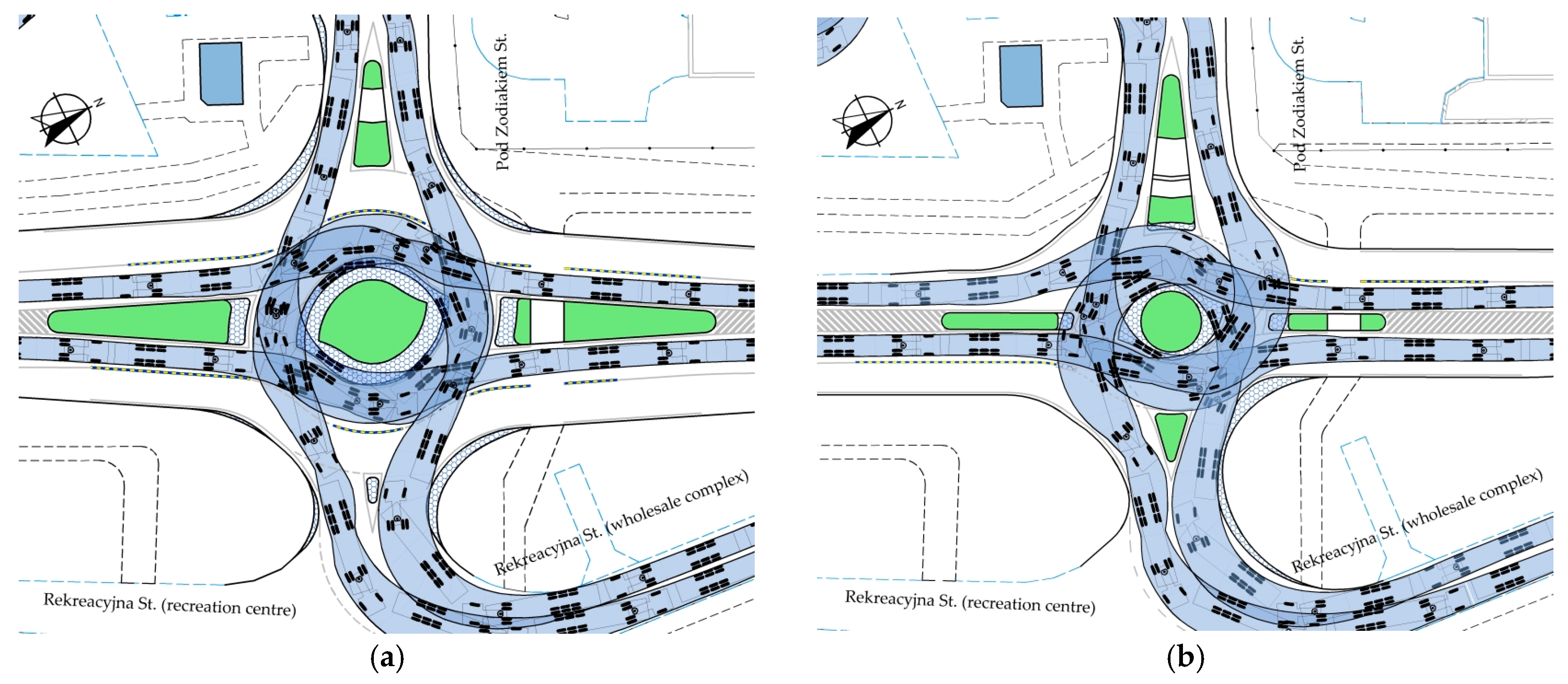
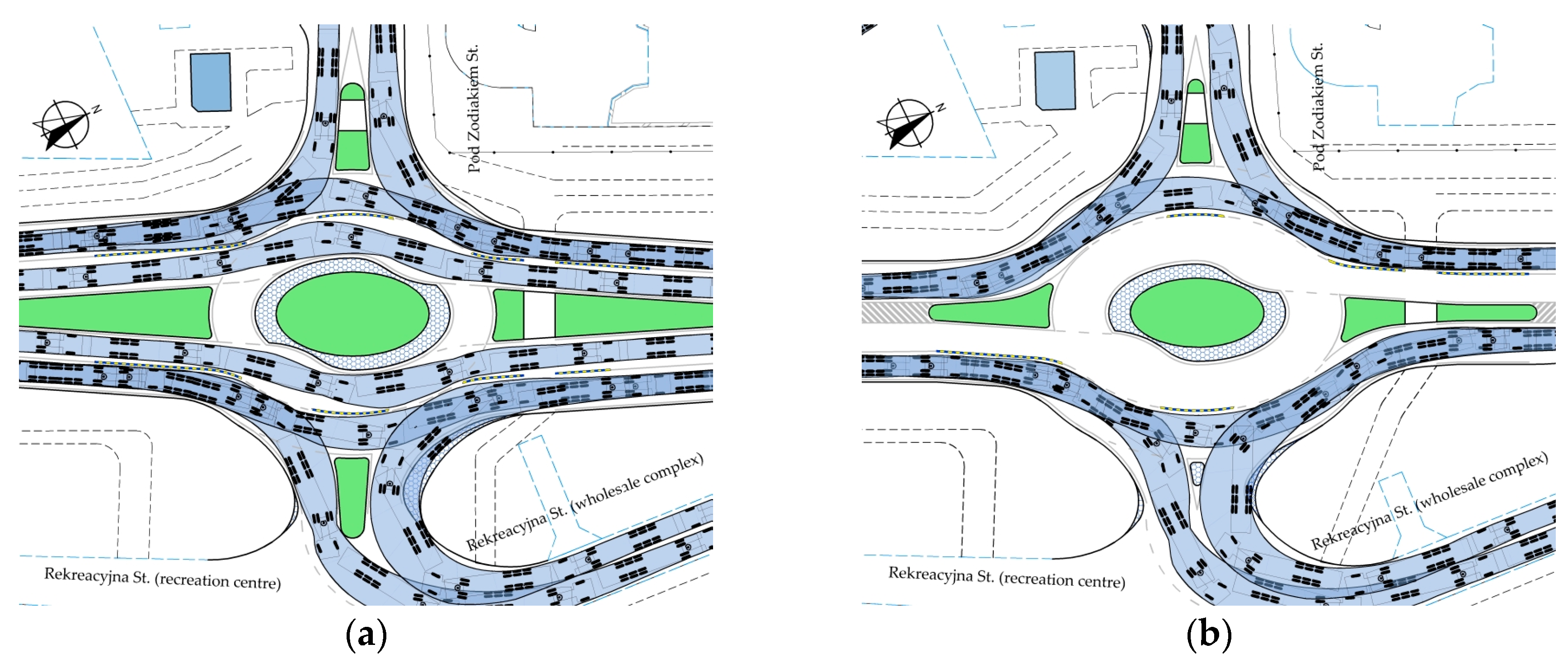
3.2. Elliptical Turbo-Roundabout Featuring a 0.24-m-Wide Separation Lane and a Standard Shape Central Island

Next, elliptical turbine roundabouts were analysed, laid out on the basis of the theory of ellipses, described by Prof. Grabowski [16]. In this case, the design process included DV1 swept path analysis for sensitive movements. Carrying out the swept path analysis during roundabout layout planning ensured adequate widths for both the truck apron and the roundabout carriageway lanes. This method follows from the mentioned studies of Corriere and Guerrieri [18] and Chan and Livingston [30,31]. In the turbo block design, the authors proposed sequential adoption of ellipses for a given roundabout element, based on the swept path analyses with iteratively determined small and large ellipse radii, as per Figure 13. In the case of the turbo block shown in Figure 13b featuring one exit lane on the main approach leg, only fragments of ellipses were shown in the first and third quarters of the Cartesian system. This is so because two lanes will be drawn only in this part of the designed roundabout. The outermost lane of the main approach legs will be dedicated exclusively to the right-turn movement from the main road to the side road. Figure 13 shows a turbo block of a mini elliptical turbo-roundabout. The initial value of the truck apron outer kerb radius was based on the DV1 swept path analysis for the main approach leg left-turn movement. All the entry and exit lane curve radii and widths were taken in the same way as described in Section 3.1 above. The parallel splitter island on the main approach legs was 2 m wide. The curves in Figure 13 of the following radii: Ra, Rb, Rc, and all ellipses are laid out from the point of intersection of the approach leg centrelines, labelled “O” in Figure 13. The radii of the ellipses shown in Figure 13b were taken based on the land constraint and design vehicle swept path analyses treated on an equal basis.
The analysis of the elliptical turbo-roundabout geometrical data showed that this type allows obtaining smaller values of the most important roundabout parameter, that is, the front-end spacing of the side leg splitter islands, measured along the side leg centrelines (Figure 14).
Figure 14 shows examples of elliptical turbine roundabouts with highly varied side (by ca. 10 m) side leg splitter island spacing due to using only one lane on the roundabout carriageway with additional right-turn lanes in quarters I and III.
Mountable aprons were required by the result of the critical (i.e., left-turn) swept path analysis (Figure 15). These may vary in the shape and surface area, being very long and only up to 0.30 m wide at the two main leg exit lanes (Figure 15a) or shorter and up to 1–2 m wide at the main exit lane of single-lane roundabouts (Figure 15b). Large mountable aprons on single exit lane roundabouts are associated primarily with the swept path requirement of the side leg right-turn entry lane (Appendix E, Figure A7). Note that both elliptical turbo-roundabout designs entail higher investment and future maintenance or repair costs for the roundabout pavements and mountable aprons. In addition, as was the case with single exit lane “flattened” turbine roundabouts (Figure 11b), widened traversable areas are required at the ends of U-25 separators (Figure 15b).

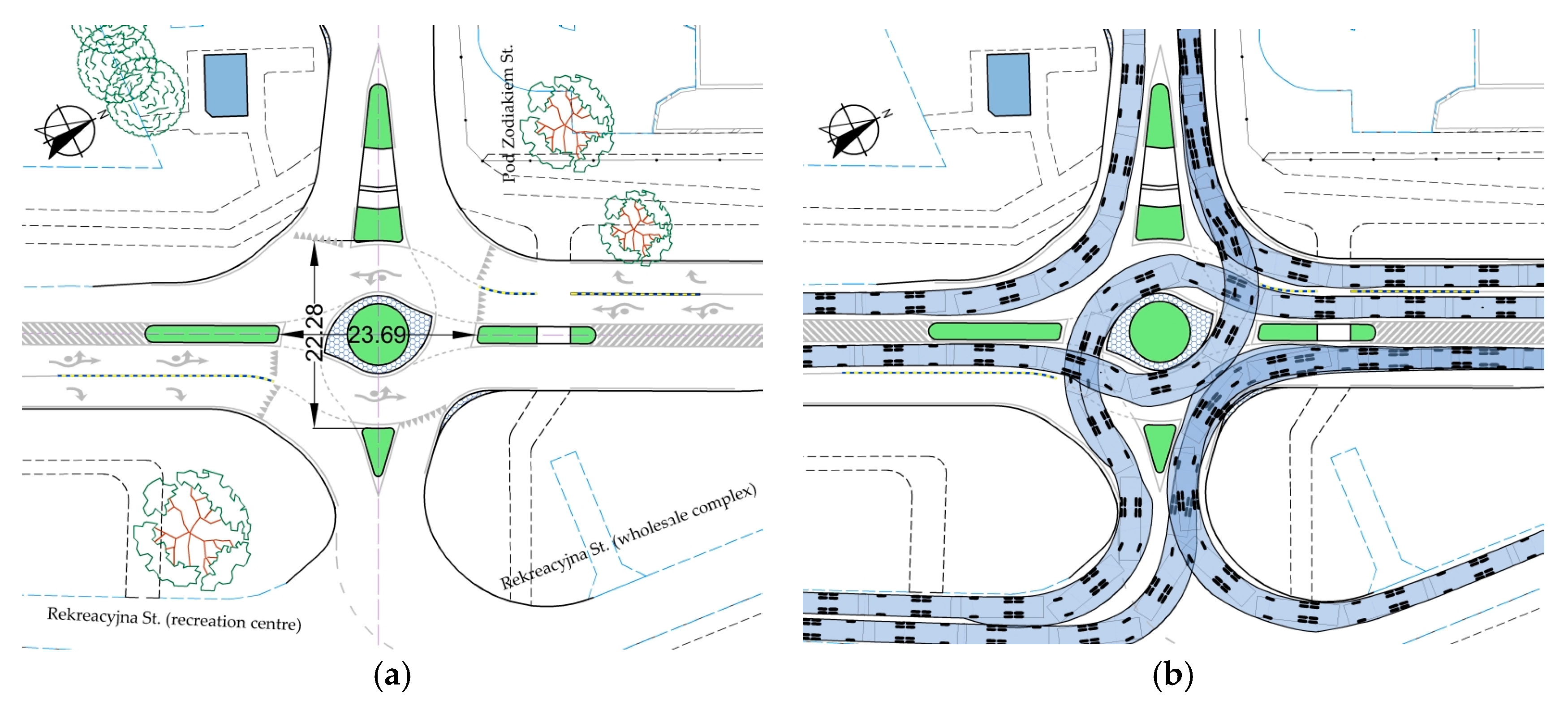
3.3. Elliptical Turbo-Roundabout Featuring a 0.2-m-Wide Separation Lane and an Elliptical Central Island

The next, in turn, are elliptical roundabouts with an elliptical central island. In the previous analyses described in Section 3.1 and Section 3.2, the swept path analysis required adjustments to individual roundabout elements. Dedicated right-turn lanes on roundabouts with a single exit lane on the main legs are likely to mislead or confuse the road users (Figure 11b and Figure 14b). Therefore, in the following roundabouts, the outer lane will be used for straight-through and right-turn movements, while the inner lane will be dedicated to left-turn movements. This traffic organisation is in line with the analyses of various traffic flow scenarios described in Section 1. The various roundabout designs are proposed considering an increase in the roundabout capacity, as may be required. The proposed turbo blocks for laying out elliptical roundabouts featuring an elliptical central island are shown in Figure 16 below. Figure 16 shows a turbo block of an elliptical turbo-roundabout. The initial value of the truck apron outer kerb radius was based on the DV1 swept path analysis for the main approach leg left-turn movement. All the entry and exit lane curve radii and widths were taken in the same way as described in Section 3.1 and Section 3.2 above. The curves in Figure 16 for the following radii: Ra, Rb and all ellipses are laid out from the point of intersection of the approach leg centrelines. The parameters and radii of the ellipses shown in Figure 16 are based on DV1 swept path analysis.
Initially, 2-m-wide parallel splitter islands were adopted on the main approach legs, the same as in “flattened” roundabouts, which were subsequently, following the swept path analysis, changed to triangular 1:15 taper islands. Additionally, the splitter island spacing was increased considerably, based on the swept path analysis, to avoid mountable aprons on the main approach legs. Considering the close proximity of any adjacent main road, junctions with hatched areas have been used after splitter islands to accommodate additional left- or right-turn lanes before these junctions. The final layouts of these roundabouts are shown in Figure 17.
The analysis of the geometrical data of the analysed roundabouts (Figure 17) showed that, compared to the roundabouts analysed in Section 3.1 and Section 3.2 above (Figure 11 and Figure 14), the turbo-roundabouts with an elliptical central island and the adopted traffic organisation had greater values of the key design parameters. These parameters are critical for design in constrained sites, as the decisive parameters in this case were the required inner (Figure 18a) and outer (Figure 18b) lane widths determined by the output of the DV1 swept path analysis for the left-turn movement. The other swept paths are shown in Figure A8 in Appendix E.

4. Discussion

The analysis of the obtained turbo-roundabout design, presented in Section 3 above, showed high geometrical diversity, a requirement for traversable splitter islands, and different surface areas of the required mountable aprons. Worth noting is also the unusual requirement for traversable parts after U-25 separators between the pedestrian crossing and at the beginning of the roundabout carriageway (Figure 11 and Figure 14). In “flattened” roundabouts, traversable parts were also required at the beginning of splitter islands to avoid considerable widening of the roundabout carriageway lane (Figure 11). Apart from the key parameters, the proposed roundabouts have considerably different traffic organisation, specifically the division of the roundabout carriageway into traffic lanes (Figure 11 and Figure 14 and Figure 17). Therefore, it is not possible to recommend a specific roundabout design from among the proposed ones as an option of choice for severely constrained sites based solely on the dimensional and swept path analyses.
Consequently, additional input conditions were defined by the authors in relation to the side road site characteristics using the diagram in Figure 9:
(a)
LUDA low urbanisation degree areas—single family housing estates or woonerf: the side road handles the local traffic composed mainly of the residents’ passenger cars and municipal service vehicles if appropriate,
(b)
BA built-up area with a developed community infrastructure, requiring the provision of pedestrian and cycle crossings running through splitter islands on the side approach legs,
(c)
CDA highly commercially developed area along the side road, including primarily wholesale complexes, very big warehouses and wholesale markets, resulting in high volumes of articulated trucks on turn movements.
For the adopted input conditions, following roundabout geometry and swept path analyses, geometrical, community and traffic engineering determinants were derived, the last related to the traffic organisation adopted for the roundabout carriageway and the respective approach legs. The determinant analysis results and recommended roundabout type are represented in Figure 19.
In Figure 19, the following colour coding system was implemented for rating the determinants:
Dark blue means a good score, i.e., lower cost, bigger pedestrian and cycling amenities, better handling of traffic in the roundabout area by adequate traffic flow allocation: two traffic lanes for the straight movements for high traffic volumes on the main road or a dedicated turn lane for a high, heavy traffic volume for this movement, etc.
Light blue means the opposite score, i.e., less pedestrian and cyclist amenities, no dedicated right- or left-turn lanes despite a high heavy-traffic volume, etc.
Blue designates an intermediate score.
The geometrically related key determinants of the roundabout size in constrained sites include:
number of straight-through lanes on the roundabout carriageway, G1,
number of traffic lanes on the main approach legs, G2,
spacing of splitter islands dividing, measured along the side road, G3.
The highest score was given to a determinant if the factor was found to be highly relevant to the roundabout size reduction. Lower scores were given to the size-increasing determinants.
The community-related determinants include:
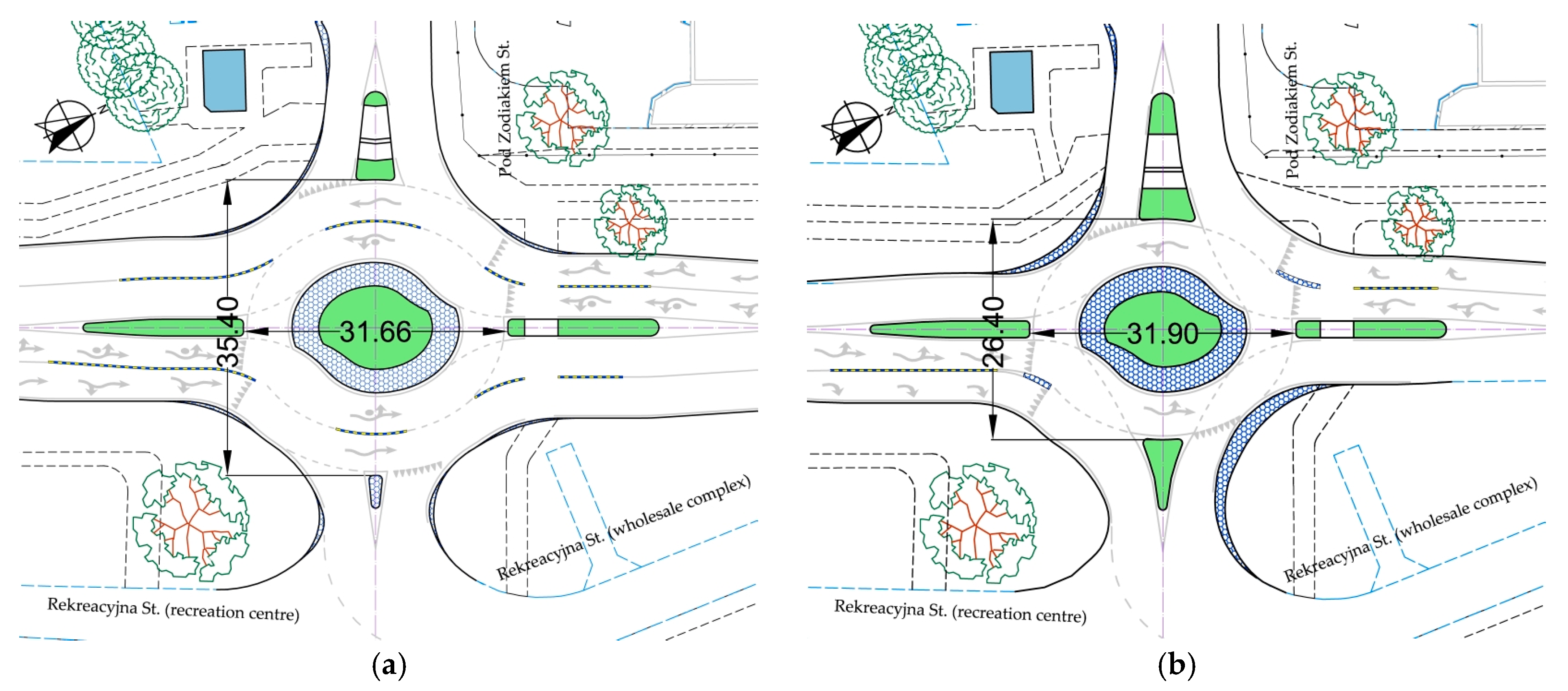
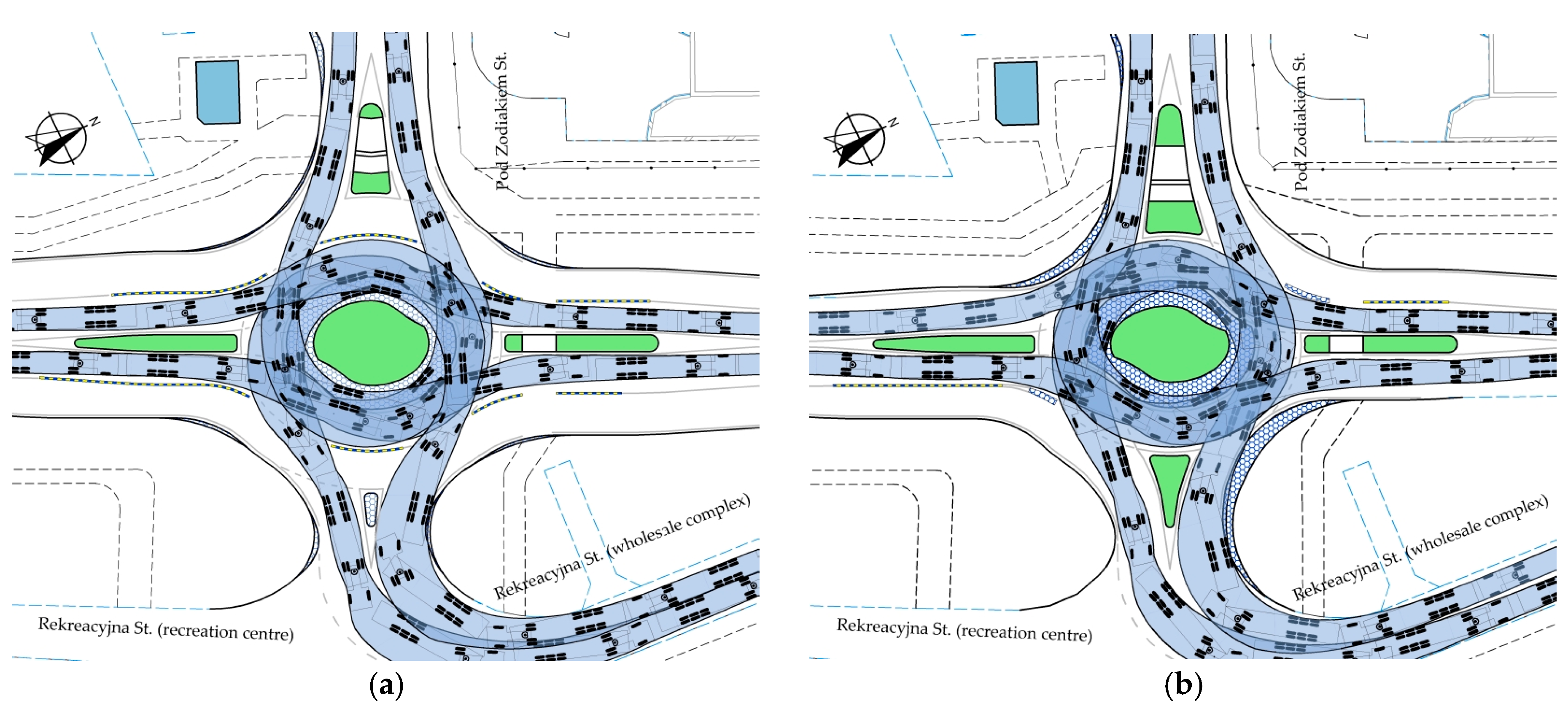
spacing of splitter islands on the main road approach legs, which, upon exceeding a certain limit, may require reconstruction of the bus stops, as may be located, for example, near the analysed intersection, or longer pedestrian travel distances to these bus stops, C1; this increases the cost as a result (Figure 11a and Figure 17),
the spacing of splitter islands on the main road approach legs increases the pedestrian travel distances to the pedestrian crossings and the nearby parking areas, S2, at the main approach legs, resulting in longer pedestrian crossings and longer accesses to nearby C2 car parks; this increases the cost as a result (Figure 11a and Figure 17),
spacing of splitter islands on the side legs, which, upon exceeding a certain limit in a constrained site, may preclude provision of a cycle crossing through the side road, C3, and thus the roundabout type may get the lowest score and may be discouraged for highly urbanised areas featuring a highly developed cycling infrastructure (Figure 11a and Figure 17),
requirement of mountable apron areas over pedestrian crossing width C4, causing disturbance to pedestrian traffic, especially for people on wheelchairs, and thus this roundabout type may get the lowest score and may be discouraged for highly urbanised areas featuring a highly developed community infrastructure,
requirement for traversable parts at the beginning of splitter islands C5, which increases the travel distance to pedestrian crossings and possibly affects traffic safety, thus resulting in a lower score given for this roundabout.
In the community-related criterion, the lowest scores were given to all the determinants that increase cost, compromise amenities, and increase pedestrian travel distances. In regards to mountable apron areas, it was assumed that in urban areas over the pedestrian crossing widths, the mountable apron surface areas should be minimised to avoid inconvenience to pedestrians with baby prams and people in wheelchairs. Thus, the determinants resulting in improved pedestrian and cyclist amenities, including shorter travel distances and small, if any, mountable apron area facilities for pedestrians and cyclists, i.e., shorter access times and the lack of or smaller areas of dirt mountable apron areas, were given the highest scores.
The third criterion is related to the adopted traffic organisation and has a major effect on the final traffic handling capacity of the roundabout under analysis. However, focusing on the method of selection of roundabouts for constrained sites, this article does not deal with capacity issues as such. The issue of turbo-roundabout capacity estimation is presented in Section 1, which is the literature review report. In deriving the traffic engineering determinants, in accordance with the conclusions of [7,8,20,22,35], it was concluded that the roundabout type selection should be based primarily on the local site conditions and traffic flow requirements on the main or side roads, taking into account the site characteristics and the adopted traffic flow allocation. Therefore, the following traffic engineering determinants were adopted:
the required number of straight-through traffic lanes on the roundabout carriageway has a considerable effect on the roundabout capacity when dealing with high traffic volumes carried by the main road, TE1,
the number of main road exit lanes has a considerable effect on the roundabout capacity when dealing with high traffic volumes carried by the main road, TE2,
distance to adjacent junctions on the main road requires provision of additional traffic lanes before them, which, in the case of close proximity of such junctions, has a considerable bearing on the carriageway division into traffic lanes on the approach to the analysed roundabout and the installation of appropriate road surface markings, TE3,
high left-turning traffic volume, requires, for example, the provision of a dedicated traffic lane on the roundabout carriageway TE4,
high right-turning traffic volume, requires, for example, the provision of a dedicated traffic lane on the roundabout carriageway TE5.
It should also be checked whether a coordinated traffic management scheme has been applied on the main road between subsequent intersections. Where signalised junctions are in close proximity to the roundabout, two straight-through lanes on the roundabout carriageway and a hatched area after the splitter island on the main approach legs were considered the best ways to avoid roundabout entry queues. Then, appropriate lanes should also be provided before the next signalised junction.
Figure 19 represents the assessment of the adopted determinants, as defined above, in accordance with the roundabout selection chart in Figure 9 for constrained project sites. The analysis of these determinants using three different assessment criteria allowed the recommendation of the roundabout type depending on the site features.
Thus, in the most constrained, low urbanisation degree areas of LUDA, where the side road handles generally local traffic with DV1 design vehicles occurring only incidentally, a type II roundabout (“flattened” turbo-roundabout with a single lane on the main road approach leg) would be recommended as the option of choice. This choice will minimise the size, and thus also the project cost, and keep interference with the existing pedestrian and cycle infrastructure at a reasonable level. This means no mountable aprons on pedestrian and cycle crossings and the same travel distance to the roundabout, subject to correct placement. In addition, the type II turbo-roundabout considerably improves the flow of traffic turning from the main road to the side road, resulting in a considerable increase in capacity as compared to the existing junction. Figure 20a shows a modified roundabout type II with no mountable aprons and smaller in size, as appropriate for traffic composed of passenger cars and municipal service vehicles DV2 only. Figure 20b, in turn, shows the DV2 swept paths.
For built-up areas featuring well-developed community infrastructure, BA requires pedestrian and cycle crossings to run through splitter islands on the side legs, with less severe site constraints and a considerable share of heavy traffic on the left- and right-turn movements, type VI roundabout (elliptical turbo-roundabout with an elliptical central island and one exit lane on the main road approach leg) is recommended as the option of choice. This roundabout also provides all the pedestrian and cyclist amenities, i.e., it can be designed without mountable aprons encroaching on the pedestrian or cycle crossings. This roundabout is significantly larger (with almost two times greater splitter island spacing) than the type II roundabout, thus requiring fewer severe site restrictions.
In areas with rapidly growing commercial developments, a CDA type III roundabout (an elliptical roundabout with two lanes on the main road approach leg) would be the option of choice owing to the smaller spacing of splitter islands on the side legs. Its only advantage over the other roundabouts featuring two exit lanes on the main road approach leg is the smallest spacing of the side leg splitter islands, which in the case under analysis allows accommodating a cycle crossing on the western approach leg. The disadvantage of this option is that 0.30–0.45-m-wide mountable apron areas encroach on the pedestrian crossing. However, type V roundabouts were identified as the most recommended option for CDA sites when the roundabouts with two exit lanes were analysed for the three predetermined criteria. Despite the greatest spacing of splitter islands on the main approach legs, this option provides high capacity, smoother DV1 swept paths on turning movements, a lack of mountable aprons on pedestrian crossings, and much larger soft landscaping areas, considered an environmentally friendly feature. That said, one drawback can be noted in this particular case: cycle crossings cannot be provided in quarter I due to the existing hotel car park fence. However, as mentioned, the elliptical roundabout with an elliptical central island may be an option of choice only for areas with less severe constraints, this is due to the large splitter island spacing (Figure 11 and Figure 14 and Figure 17).

5. Conclusions

The following final conclusions can be drawn to summarise the findings of the analyses presented in this article:
The currently available turbo-roundabout design guidelines do not include turbo blocks that could be used for designing such roundabouts where site constraints are an issue.
The proposed turbo blocks for designing six types of turbo roundabouts of different shapes and roundabout carriageway divisions offer new turbo roundabout design options for constrained sites.
Based on predetermined criteria and determinants, three turbo roundabout types were recommended for constrained site projects, with the final choice depending on the adjacent land characteristics:
  • In low urbanisation degree areas LUDA (single family neighbourhoods or woonerf) with negligible heavy traffic volume and most severe site constraints, a “flattened” turbo roundabout featuring one lane on the main road approach leg should be the option of choice.
  • In built-up areas featuring well-developed community infrastructure, BA requires pedestrian and cycle crossings to run through splitter islands on the side legs. With less severe site constraints and a considerable share of heavy traffic on the left- and right-turn movements, the option of choice is an elliptical turbo roundabout with an elliptical central island and one exit lane on the main road approach leg.
  • In areas with rapidly growing commercial developments, a CDA along a side road featuring an elliptical roundabout featuring an elliptical central island and two lanes on the main road approach leg should be considered.
As the authors plan to continue the research with capacity analyses for different traffic flow allocations, new findings and roundabout selection guidelines may be expected.

Author Contributions

Conceptualization, A.S.; methodology, A.S. and S.M.; software, S.M.; validation, A.S. and S.M.; formal analysis, A.S. and S.M.; investigation, A.S. and S.M.; data curation, A.S. and S.M.; writing—original draft preparation, A.S.; writing—review and editing, A.S. and S.M.; visualization, A.S. and S.M.; supervision, A.S. All authors have read and agreed to the published version of the manuscript.

Funding

This research received no external funding.

Institutional Review Board Statement

Not applicable.

Informed Consent Statement

Not applicable.

Data Availability Statement

The data presented in this study are available upon reasoned request addressed to the corresponding author.

Conflicts of Interest

We wish to confirm that there are no known conflicts of interest associated with this article title “Design study for the construction of turbo-roundabouts under constrained site conditions”. We confirm that the manuscript has been read and approved by all named authors and that there are no other persons who satisfied the criteria for authorship but are not listed.

Appendix A

Figure A1. Illustrative junction layout plan showing site constraints—case study; distance to the junction to the south—184 m; distance to the junction to the north—234 m (all distances are in metres).
Sustainability 15 13220 g0a1

Appendix B

Figure A2. Year 2023 traffic cartogram, veh/24 h.
Sustainability 15 13220 g0a2
Table A1. Volume of traffic by vehicle, veh/h.
ApproachLeft TurningStraight ThroughRight Turning
PHGVTSUBPHGVTSUBPHGVTSUB
Volume of traffic by vehicle in hours 14–15
A2934693111249636
B6443942413044224
C981141024
D242972
Volume of traffic by vehicle in hours 5–6
A38202403388155524
B483252801892122435
C32281818
D17742827
Where: P—passenger cars; HGV—heavy goods vehicles; TSU—tractor-semitrailer units; B—buses.

Appendix C

Figure A3. Variation of daily traffic volume in years 2010, 2023, and 2043.
Sustainability 15 13220 g0a3
Figure A4. Variation of relative heavy traffic growth index in years 2010, 2023, and 2043.
Sustainability 15 13220 g0a4

Appendix D

Standard design values for egg mini and small turbo roundabouts according to Dutch guidelines [1], (Figure 6 and Figure A5).
Figure A5. Turbo block of a standard small egg turbo roundabout.
Sustainability 15 13220 g0a5
Table A2. Design values for standard egg turbo roundabouts as per Dutch guidelines [1] and “look-a-like” turbo roundabouts designed for the purposes of this article.
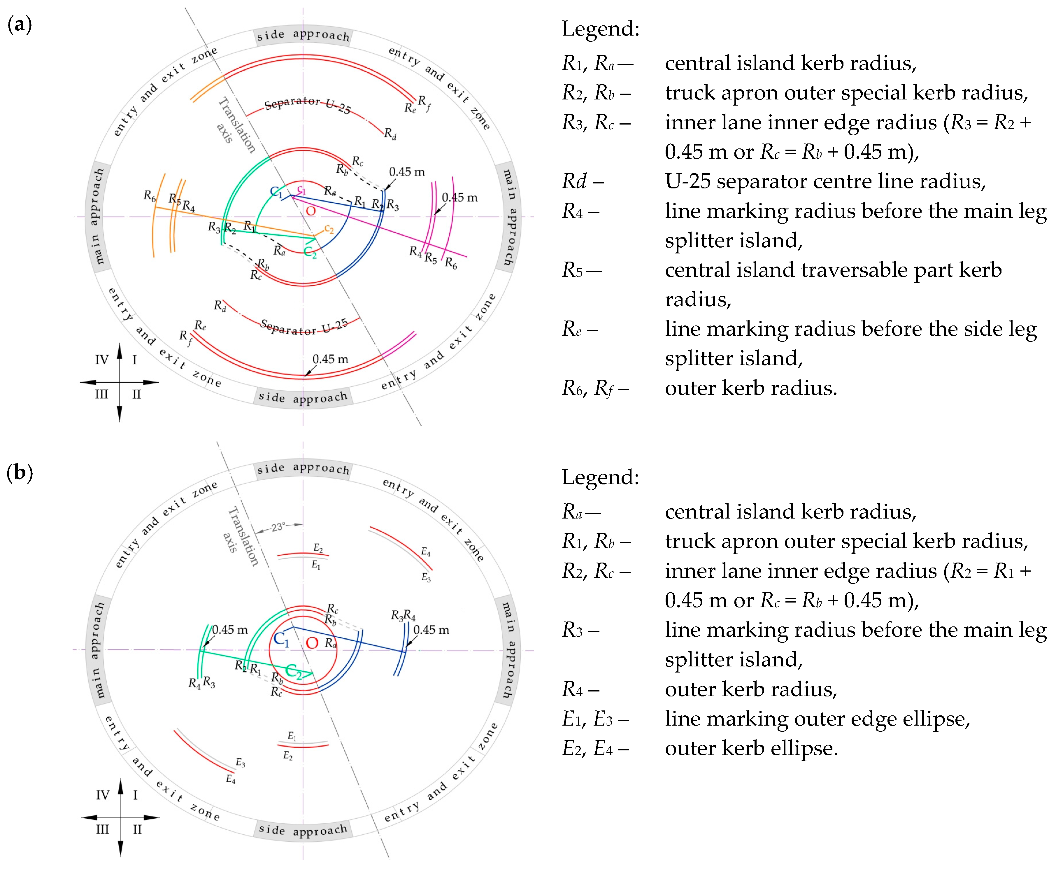
Main Elements of a Transverse Cross-Section of the RoundaboutMathematical DesignationRadius and Measurement in m
Fastest path speed for a passenger car in km/hv37–4137–39
Mini roundaboutSmall roundabout
Figure 7a and Figure A4Figure 7b
Lane divider between driving lanes 0.700.240.700.24
Radii
Inner radius of the inner laneR110.5010.5012.0012.00
Outside radius of the inner laneR215.8515.6517.1516.95
Inner radius of the outside laneR316.1515.8917.4517.19
Outside radius of the outside laneR421.1520.6922.4521.99
Curve lane divider entry Rt12121212
Curve lane divider exit Ra14141414
Widths
Overrun area (truck apron) width 5.005.005.005.00
Width, inside lanebu4.704.704.504.50
Width, outside lanebv4.354.354.354.35
Shift of inner arc centres along the translation axis(stakeout: R2, R3, R4)v5.755.755.355.35
Shift of outer arc centres along the translation axis(stakeout: R0, R1)u5.055.055.055.05

Appendix E

Figure A6. Examples of swept path analysis for “flattened” roundabouts with straight-through movements from the main approach legs plus right-turn movements: (a) with two exit lanes on the main approach legs—I type; (b) with one lane on the main approach legs—II type. Source: own work.
Sustainability 15 13220 g0a6
Figure A7. Examples of swept path analysis for elliptical turbo roundabouts with straight-through movements from the main approach legs plus right-turn movements: (a) with two exit lanes on the main approach legs—III type; (b) with one lane on the main approach legs—IV type. Source: own work.
Sustainability 15 13220 g0a7
Figure A8. Examples of swept path analysis for elliptical turbo roundabouts featuring an elliptical central island with straight-through movements from the main approach legs plus right-turn movements: (a) with two exit lanes on the main approach legs—V type; (b) with one lane on the main approach legs—VI type. Source: own work.
Sustainability 15 13220 g0a8

References

  1. Overkamp, D.P.; van der Wijk, W. Roundabouts—Application and Design, A Practical Manual; Royal Haskoning DHV, Dutch Ministry of Transport, Public Works and Water Management, Partners for Roads: Hague, The Netherlands, 2009. [Google Scholar]
  2. Fortuijn, L.G.H. Turborotonde En Turboplein: Ontwerp, Capaciteit En Veiligheid. Trail Thesis series T 2013/1. Ph.D. Thesis, Trail Research School, Dissertation of Delft University of Technology, Delf, The Netherlands, January 2013. [Google Scholar]
  3. CROW. Turborotondes; CROW Publication No. 257; CROW: Hague, The Netherlands, 2008. [Google Scholar]
  4. Fortuijn, L.; Salomons, A.M. Capacity Increase through connectivity for the i-Roundabout and i-Turbo roundabout. In Proceedings of the 2020 Forum on Integrated and Sustainable Transportation Systems (FISTS), Delft, The Netherlands, 3–5 November 2020. [Google Scholar] [CrossRef]
  5. Gallelli, V.; Vaiana, R. Safety improvements by converting a standard roundabout with unbalanced flow distribution into an egg turbo roundabout: Simulation approach to a case study. Sustainability 2019, 11, 466. [Google Scholar] [CrossRef]
  6. Liu, Q.; Deng, J.; Shen, Y.; Wang, W.; Zhang, Z.; Lu, L. Safety and Efficiency Analysis of Turbo Roundabout with Simulations Based on the Lujiazui Roundabout in Shanghai. Sustainability 2020, 12, 7479. [Google Scholar] [CrossRef]
  7. Ciampa, D.; Diomedi, M.; Giglio, F.; Olita, S.; Petruccelli, U.; Restaino, C. Effectiveness of unconventional roundabouts in the design of suburban intersections. Eur. Transp. Trasp. Eur. 2020, 80, 1–16. [Google Scholar] [CrossRef]
  8. Silva, A.B.; Mariano, P.; Silva, J.P. Performance assessment of turbo-roundabouts in corridors. Transp. Res. Procedia 2015, 10, 124–133. [Google Scholar] [CrossRef]
  9. CROW. Eenheid in Rotondes; CROW Publication: Ede No. 126; CROW: Hague, The Netherlands, 1998. [Google Scholar]
  10. De Baan, D. Aantal ‘Gespotte’ Turborotondes. Available online: https://www.dirkdebaan.nl/types.html (accessed on 2 July 2023).
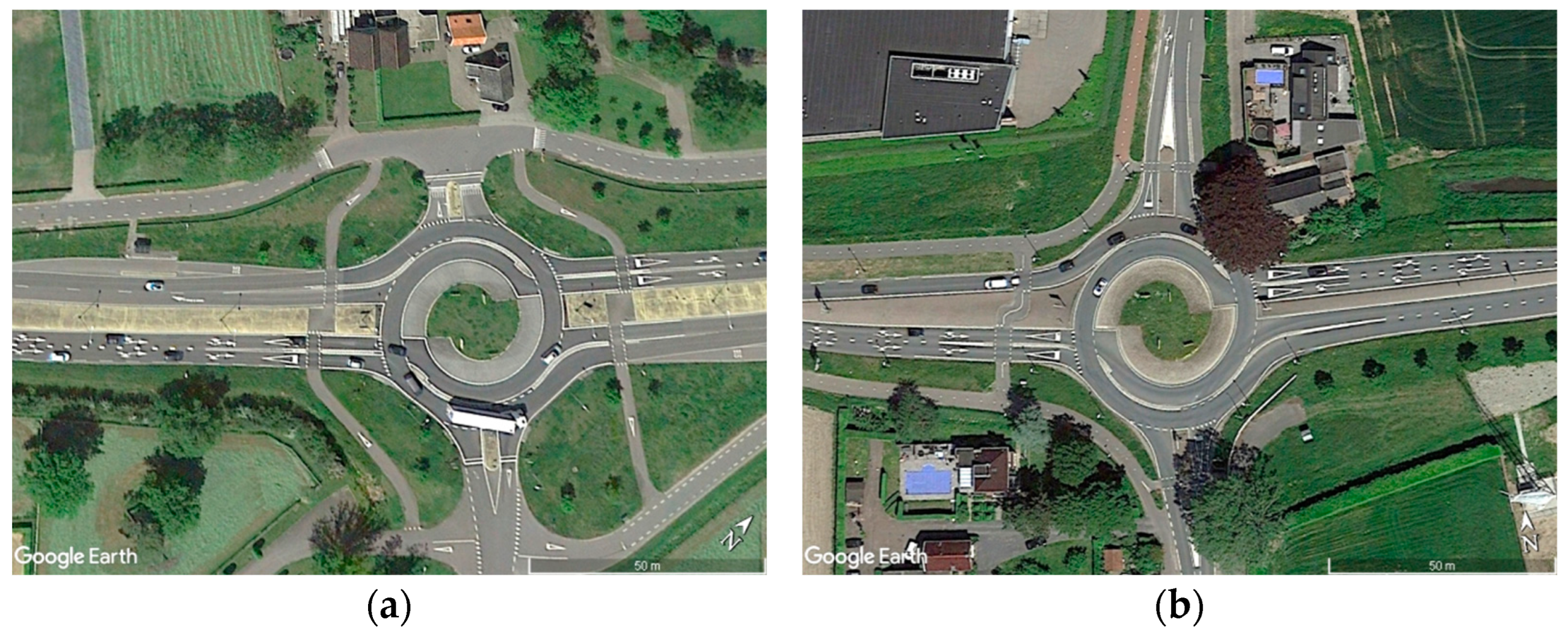
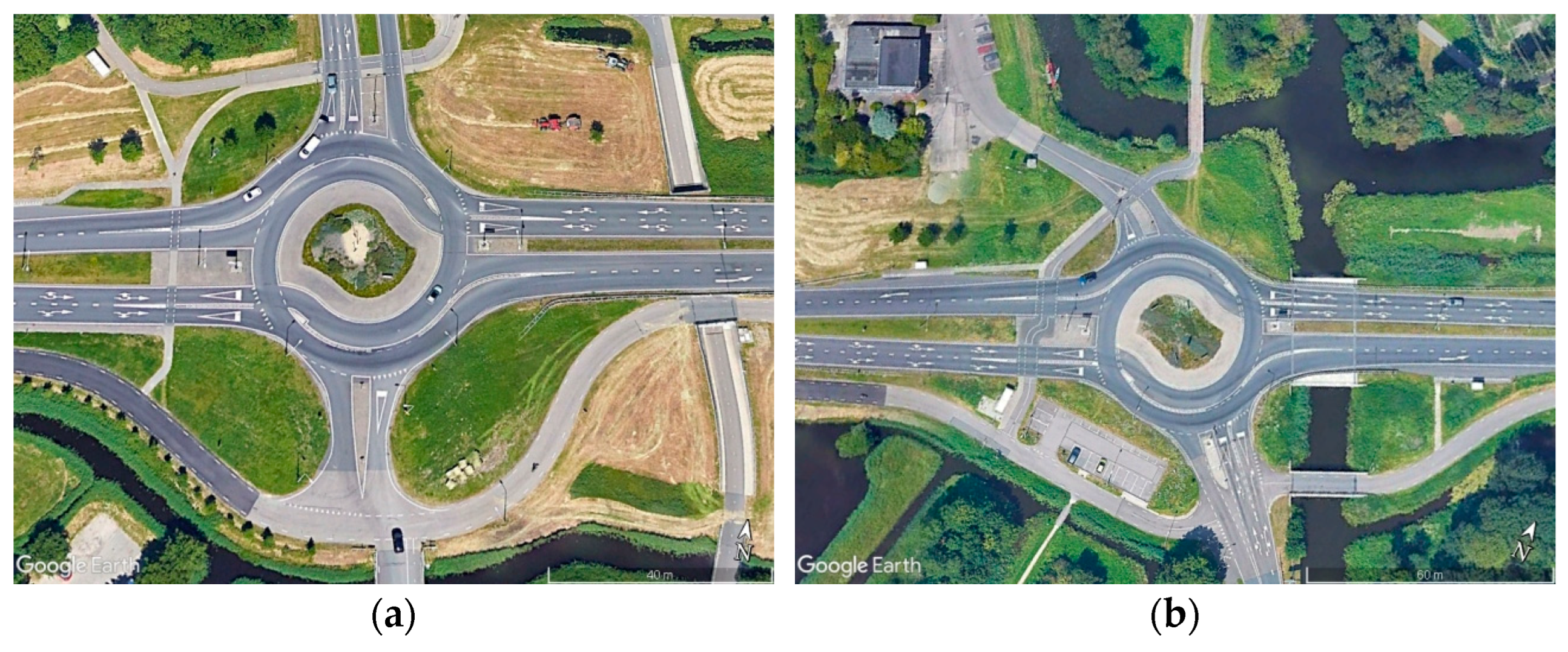
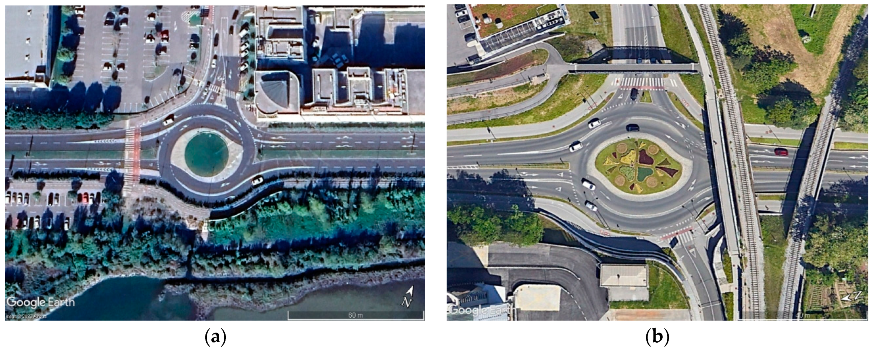
  11. Google Earth. Available online: http://www.earth.google.com (accessed on 2 July 2023).
  12. Tollazzi, T. “Turbo” Krožišča: Krožna Križišča s Spiralnim Potekom Krožnega Vozišča; Ministrstvo za Promet, Direkcija Republike Slovenije za Ceste: Ljubljana, Slovenia, 2008.
  13. Tollazzi, T.; Mauro, R.; Guerrieri, M.; Rencelj, M. Comparative analysis of four new alternative types of roundabouts: “turbo”, “flower”, “target” and “four-flyover” roundabout. Period. Polytech. Civ. Eng. 2015, 60, 51–60. [Google Scholar] [CrossRef]
  14. Tollazzi, T. Alternative Types of Roundabouts. An Informational Guide; Springer Tracts on Transportation and Traffic STTT; Springer: Berlin/Heidelberg, Germany, 2015; Volume 6. [Google Scholar] [CrossRef]
  15. Tollazzi, T. Experiences with Alternative Types of Roundabouts in Slovenia. In Proceedings of the Conference European Road Assessment (EuroRAP), Brussels, Belgium, 3–5 January 2020; Available online: https://eurorap.org/wp-content/uploads/2020/01/3-5-Tollazzi-Konferenca-o-prometni-varnosti-2016.pdf (accessed on 2 July 2023).
  16. Grabowski, R. Turbo-roundabouts as an alternative to standard roundabouts with the circular centre island. Roads Bridges Drog. Mosty 2012, 11, 215–231. [Google Scholar]
  17. Leonardi, S.; Distefano, N. Turbo-Roundabouts as an Instrument for Improving the Efficiency and Safety in Urban Area: An Italian Case Study. Sustainability 2023, 15, 3223. [Google Scholar] [CrossRef]
  18. Guerrieri, M.; Tollazzi, T. Analysis of Kinematic Parameters and Driver Behavior at Turbo Roundabouts. J. Transp. Eng. Part A Syst. 2018, 144, 04018020. [Google Scholar] [CrossRef]
  19. Vasconcelos, L.; Silva, A.B.; Seco, A.M.; Fernandes, P.; Coelho, M.C. Turboroundabouts: Multicriterion Assessment of Intersection Capacity, Safety, and Emissions. J. Transp. Res. Rec. 2014, 2402, 28–37. [Google Scholar] [CrossRef]
  20. Vasconcelos, L.; Silva, A.B.; Seco, A.M. Capacity of normal and turbo-roundabouts: Comparative analysis. Proc. Inst. Civ. Eng. Transp. 2014, 167, 88–99. [Google Scholar] [CrossRef]
  21. Pitlova, E.; Kocianova, A. Case Study: Capacity Characteristics Comparison of Single-lane Roundabout and Turbo-roundabouts. Procedia Eng. 2017, 192, 701–706. [Google Scholar] [CrossRef]
  22. Šarić, A.; Lovrić, I. Multi-lane Roundabout Capacity Evaluation. Front. Built Environ. Sec. Transp. Transit Syst. 2017, 3, 42. [Google Scholar] [CrossRef]
  23. Kocianova, A. Capacity Limits of Basic Turbo-Roundabouts. Commun. Sci. Lett. Univ. Zilina 2016, 18, 90–98. [Google Scholar] [CrossRef]
  24. Gallelli, V.; Perri, G.; Vaiana, R. Operational and safety management at intersections: Can the turbo-roundabout be an effective alternative to conventional solutions? Sustainability 2021, 13, 5103. [Google Scholar] [CrossRef]
  25. Urząd Miasta Przestrzenny Plan Zagospodarowania Przestrzennego Miasta, Urząd Miasta w Szczecinie. 2022. Available online: https://bip.um.szczecin.pl/chapter_11424.asp (accessed on 19 May 2022).
  26. GDDKiA. Generalny Pomiar Ruchu GPR 2020/2021. Available online: https://www.gov.pl/web/gddkia/generalny-pomiar-ruchu-20202021 (accessed on 25 May 2023).
  27. Rozporządzenie Ministra Infrastruktury z dnia 24 czerwca 2022 r. w sprawie przepisów techniczno-budowlanych dotyczących dróg publicznych. Dziennik Ustaw 2022. Warszawa, z dnia 20 lipca 2022 r., poz. 1518. Available online: https://isap.sejm.gov.pl/isap.nsf/DocDetails.xsp?id=WDU20220001518 (accessed on 25 May 2023).
  28. Bąk, R.; Gaca, S.; Ostrowski, K.; Tracz, M.; Woźniak, K. Wytyczne Projektowania Skrzyżowań Drogowych WR-D-31-3. Ronda; Ministerstwo Infrastruktury: Warszawa, Poland, 2022. [Google Scholar]
  29. Corriere, F.; Guerrieri, M. Performance analysis of basic turbo-roundabouts in urban context. Procedia Soc. Behav. Sci. 2012, 53, 622–632. [Google Scholar] [CrossRef]
  30. Chan, S. Radial, left or right offset alignment and roundabout vehicle speeds. Roundabouts Now 2017, 3, 24–27. [Google Scholar]
  31. Chan, S.; Livingston, R. Design Vehicle’s Influence to the Geometric Design of Turbo Roundabouts. Teach America. Retrieved 17 October 2017. 2015. Available online: http://teachamerica.com/RAB14ppr147_Chan.pdf (accessed on 25 April 2021).
  32. Campbell, D.; Jurisich, I.; Dunn, R. Improved Multi-Lane Roundabout Designs for Urban Areas; Research Report 476; NZ Transport Agency: Wellington, New Zealand, 2012. [Google Scholar]
  33. Džambas, T.; Ahac, S.; Dragčević, V. Design of turbo roundabouts based on the rules of vehicle movement geometry. J. Transp. Eng. 2016, 142, 05016004. [Google Scholar] [CrossRef]
  34. Džambas, T.; Dragčević, V.; Korlaet, Ž. Optimizing geometric design of standard turboroundabouts. KSCE J. Civ. Eng. 2020, 24, 3034–3049. [Google Scholar] [CrossRef]
  35. Severino, A.; Pappalardo, G.; Trubia, S. Safety evaluation of turbo roundabout considering autonomous vehicles operation. Arch. Civ. Eng. 2021, LXVII, 439–460. [Google Scholar] [CrossRef]
Figure 1. Examples of standard egg turbo-roundabouts located in constrained areas in the vicinity of buildings in The Netherlands: (a) Wierden (52°20′39.79” N, 6°34′23.27” E); (b) Krimpen aan den IJssel (51°48′36.17” N, 4°26′7.30” E). (Source: Google Earth [11]).
Sustainability 15 13220 g001
Figure 2. Examples of standard egg turbo-roundabouts located in constrained areas near lakes or canals in The Netherlands: (a) Wierden (51°54′43.29” N, 4°38′34.10” E); (b) Krimpen aan den IJssel (51°54′29.61” N, 4°37′23.73” E). (Source: Google Earth [11]).
Sustainability 15 13220 g002
Figure 3. Examples of non-standard “flattened” turbo-roundabouts located in a constrained, built-up area in Slovenia: (a) Koper (45°32′33.37” N, 13°44′21.78” E); (b) Maribor (46°33′4.09” N, 15°38′59.64” E). (Source: Google Earth [11]).
Sustainability 15 13220 g003
Figure 4. The turbo roundabout selection method for constrained areas is presented in the diagram.
Sustainability 15 13220 g004
Figure 5. Location of the selected junction on DK13 national road in the suburbs of Szczecin. Source: own work using the Szczecin Master Plan image [25].
Sustainability 15 13220 g005
Figure 6. Discouraged parking options: (a) parking on the local street; (b) improper parking near Biedronka supermarket; (c) entry to the “illegal” parking site from the pedestrian crossing; (d) illegal parking site. (Photo by: A. Sołowczuk).
Sustainability 15 13220 g006aSustainability 15 13220 g006b
Figure 7. Constraints and selected parameters of Egg turbo roundabout located in the outskirts of Szczecin—A case study: (a) 0.7 m wide raised separation lane, inner lane started in the old manner; (b) 0.24 m wide separation lane, inner lane started in a new manner. Source: own work on a satellite image background, roundabout site example from Google Earth [11].
Sustainability 15 13220 g007
Figure 8. Examples of different separation lanes used in Poland: (a) Szczecin (53°25′16.84” N, 14°31′40.99” E)—“look-a-like” turbo-roundabout—separation lane consisting of line markings only; (b) Dziwnówek (54° 1′56.65” N, 14°48′26.53” E)—non-standard turbo-roundabout (whit single, two and three circulating lanes—traversable splitter island and line marking as the approach separation; (c) 0.24 cm wide separation consisting of a line marking and U-25 raised separator; (d) detail of U-25 separator attached to the pavement on the line marking. (Photo by A. Sołowczuk).
Sustainability 15 13220 g008
Figure 9. Nonstandard turbo-roundabout step-by-step selection diagram for constrained project sites.
Sustainability 15 13220 g009
Figure 10. Turbo block to layout “flattened” roundabouts: (a) with two exit lanes on the main approach legs—I type; (b) with one lane on the main approach legs—II type. Source: own work. The icon Sustainability 15 13220 i003
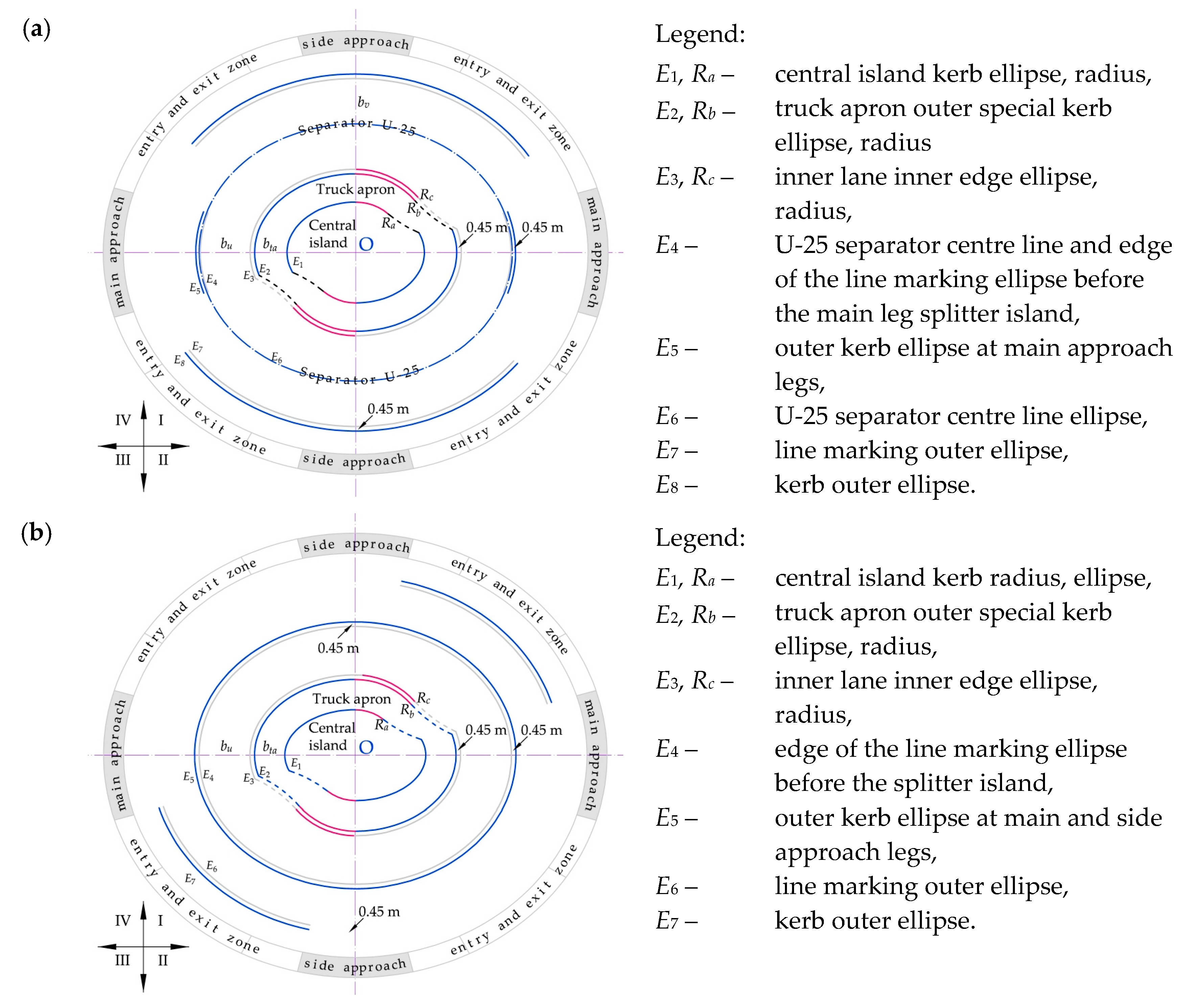
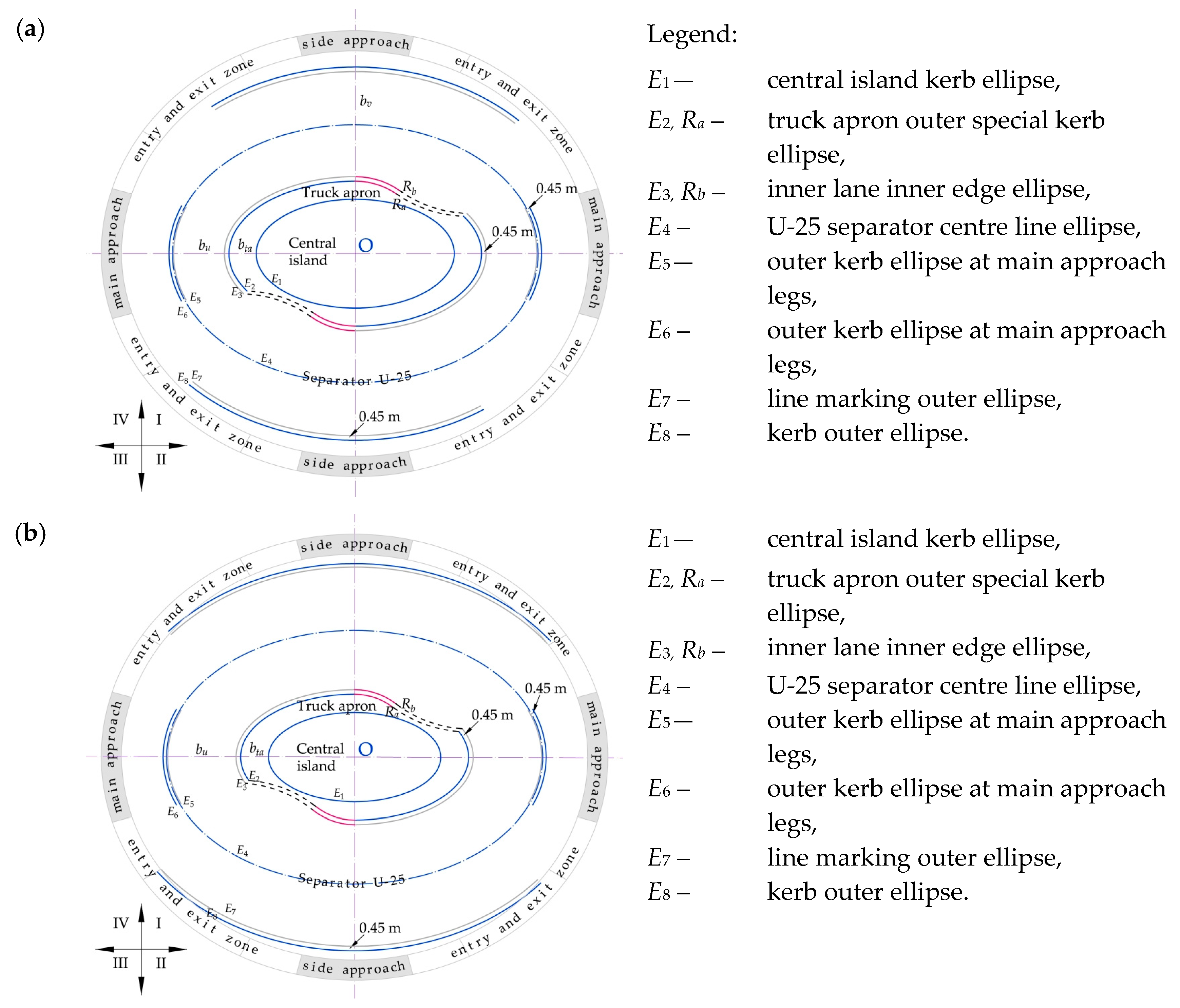
shows the Cartesian quadrants.
Sustainability 15 13220 g010
Figure 11. Examples of “flattened” roundabouts: (a) with two exit lanes on the main approach legs—I type; (b) with one lane on the main approach legs—II type. Source: own work.
Sustainability 15 13220 g011
Figure 12. Examples of swept path analyses for “flattened” roundabouts left-turn movements: (a) with two exit lanes on the main approach legs—I type; (b) with one lane on the main approach legs—II type. Source: own work.
Sustainability 15 13220 g012
Figure 13. One exit lane at main approach legs. Turbo block for laying out elliptical turbo-roundabouts: (a) with two exit lanes on the main approach legs—III type; (b) with one lane on the main approach legs—IV type. Source: own work.
Sustainability 15 13220 g013
Figure 14. Examples of elliptical turbo-roundabouts: (a) with two exit lanes on the main approach legs—III type; (b) with one lane on the main approach legs—IV type. Source: own work.
Sustainability 15 13220 g014
Figure 15. Examples of swept path analyses for elliptical roundabout left-turn movements: (a) with two exit lanes on the main approach legs—III type; (b) with one lane on the main approach legs—IV type. Source: own work.
Sustainability 15 13220 g015
Figure 16. Turbo block for laying out elliptical turbo- roundabouts featuring elliptical central island: (a) with two exit lanes on the main approach legs—V type; (b) with one lane on the main approach legs—VI type. Source: own work.
Sustainability 15 13220 g016
Figure 17. Examples of elliptical turbo-roundabouts with an elliptical central island: (a) with two exit lanes on the main approach legs—V type; (b) with one lane on the main approach legs—VI type. Source: own work.
Sustainability 15 13220 g017
Figure 18. Examples of swept path analyses for elliptical roundabouts featuring an elliptical central island: (a) with two exit lanes on the main approach legs—V type; (b) with one lane on the main approach legs—VI type. Source: own work.
Sustainability 15 13220 g018
Figure 19. Analysis of the adopted determinants and selection of the turbo-roundabout type for constrained site projects.
Sustainability 15 13220 g019
Figure 20. Example of “flattened” turbo-roundabout with a single traffic lane on the main road approach leg, recommended for areas of low urbanisation degree LUDA—single-family neighbourhoods or woonerf: (a) roundabout; (b) swept path DV2. Source: own work.
Sustainability 15 13220 g020
Table 1. Parameters of the selected DVs based on the guidelines of [27].
Design Vehicle DataVehicle Details
LMABS 1L2FWBB2WB2
DV1 Sustainability 15 13220 i00116.507013.431.624.813.926.15
DV2 Sustainability 15 13220 i0029.901.534.77
1 Max angle between segments, °.
Disclaimer/Publisher’s Note: The statements, opinions and data contained in all publications are solely those of the individual author(s) and contributor(s) and not of MDPI and/or the editor(s). MDPI and/or the editor(s) disclaim responsibility for any injury to people or property resulting from any ideas, methods, instructions or products referred to in the content.

