


Design of Turbo-Roundabouts Based on the Rules of Vehicle Movement Geometry on Curvilinear Approaches


Abstract
1. Introduction
2. Materials and Methods
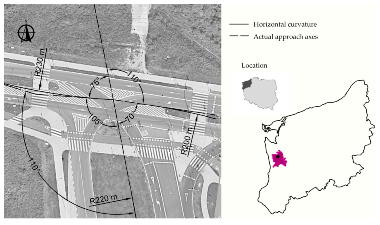
2.1. Study Area
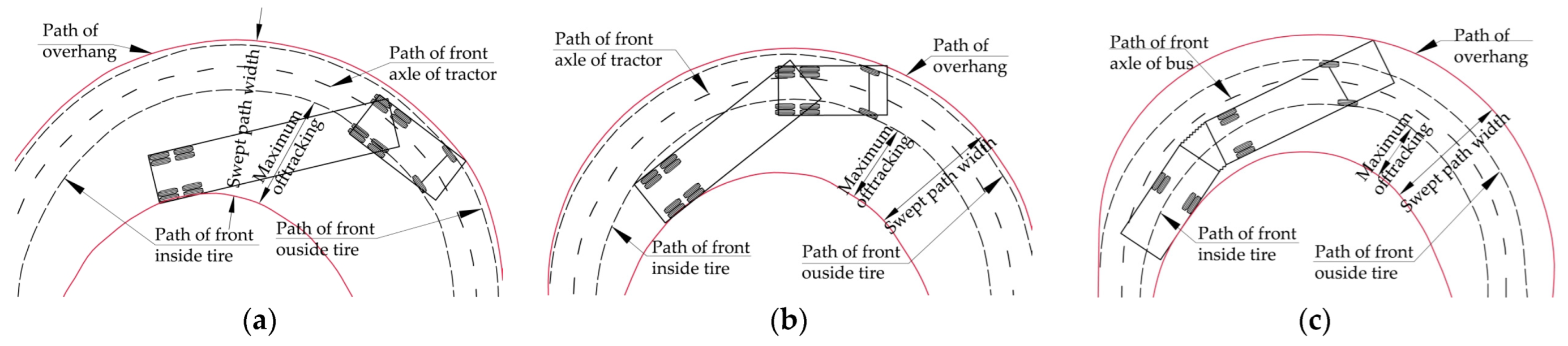
2.2. Design Vehicles and Swept Path
2.3. Methods
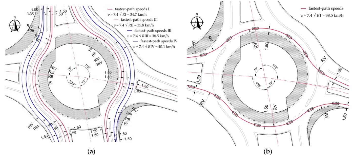
2.4. Fastest Path Passenger Car Speed Analysis
3. Results
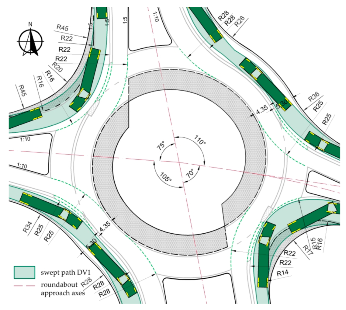
3.1. An Analysis of Vehicle Swept Paths on the Basic Turbo-Roundabout with Standard Geometry Parameters
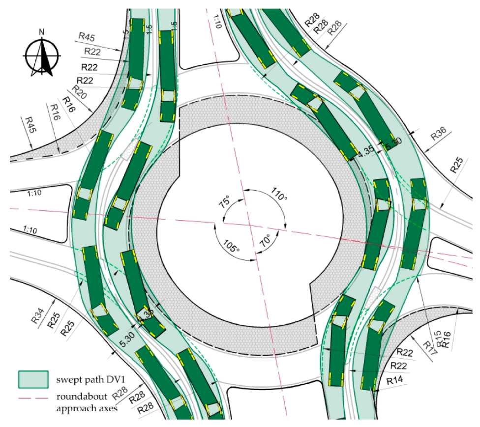
3.2. An Analysis of the Swept Paths on a Basic Turbo-Roundabout after the Widening of Circulatory Lanes
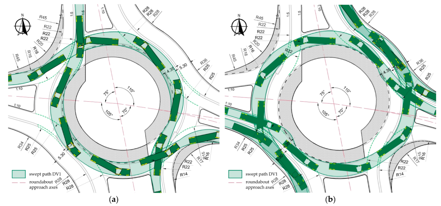
3.3. An Analysis of the Swept Paths on the Basic Turbo-Roundabout following Changes in the Roundabout Parameters
4. Discussion
5. Conclusions
- −
- Any design of a turbo-roundabout should include the swept paths analysis and the speed analysis for a passenger car travelling along the fastest path through the roundabout in order to verify the correctness of its geometric design essential for ensuring traffic safety;
- −
- The swept path analysis should be a basis for the adjustment of the basic parameters of a turbo-roundabout with curvilinear approaches at a non-right angle;
- −
- In every case, the process of turbo-roundabout design should involve a strict selection of possible design vehicles on the basis of traffic surveys conducted at the location in question, as their parameters significantly influence the roundabout geometry parameters and, consequently, the required land take area;
- −
- The use of only the 16.5 m-long design vehicle in each roundabout design case has a significant effect on the circulatory lane widths and on the so-called “opening width” of the roundabout;
- −
- In the case of curvilinear approaches oriented non-perpendicular to each other, detailed vehicle-swept path analyses should be carried out on each approach and for each movement, as the approach geometry parameters depend on its curvature,
- −
- for curvilinear approaches, a swept path analysis for the movements using the inner lane should be carried out in the first step, and the vehicle swept paths for movements using the outer lane should be examined next;
- −
- Given the positive effects of the widening of both circulatory lanes, further analyses of the swept paths should be carried out accordingly for all entries and exits and the values of splitter island and raised separation lane curvature radii and outer curb radii should be adjusted accordingly to the curvature of the respective approach;
- −
- On approaches oriented to each other at ca. 70–75°, the necessity of installing a large mountable apron should be taken into account. Its size will depend on the width of the designed splitter island;
- −
- If the design provides for 3 m-wide splitter islands, as recommended in the guidelines, and even if straight approaches are designed, there is a need for significant deflection of the edge of the splitter island and the traffic lanes at the entry to the roundabout to satisfy swept path requirements, i.e., to ensure that wheels of the travelling vehicles overrun neither the truck apron nor the raised separation lanes;
- −
- In the case of curvilinear approaches oriented to each other at the angle of ca. 105–120°, installation of the mountable apron may be avoided if larger curve radii are used.
Author Contributions
Funding
Institutional Review Board Statement
Informed Consent Statement
Data Availability Statement
Conflicts of Interest
Appendix A


References
- Fortuijn, L.G.H. Turborotonde en Turboplein: Ontwerp, Capaciteit en Veiligheid. Ph.D. Thesis, Delft University of Technology, Delf, The Netherlands, 2013. (In Dutch). [Google Scholar]
- CROW. Eenheid in Rotondes; Publication Ede No. 126; CROW: The Hague, The Netherlands, 1998. (In Dutch) [Google Scholar]
- De Baan, D. Aantal ‘Gespotte’ Turborotondes. Available online: https://www.dirkdebaan.nl/locaties.html (accessed on 2 July 2022). (In Dutch).
- CROW. Turborotondes; Publication No. 257; CROW: The Hague, The Netherlands, 2008. (In Dutch) [Google Scholar]
- Overkamp, D.P.; van der Wijk, W. Roundabouts—Application and Design—A Practical Manual; Royal Haskoning DHV, Dutch Ministry of Transport, Public Works and Water Management, Partners for Roads: Hague, The Netherlands, 2009. [Google Scholar]
- Engelsman, J.C.; Uken, M. Turbo roundabouts as an alternative to two lane roundabouts. In Proceedings of the 26th Southern African Transport Conference (SATC 2007), Pretoria, South Africa, 9–12 July 2007. [Google Scholar]
- Fortuijn, L.G.H. Turbo roundabouts: Design principles and safety performance. J. Transp. Res. Board 2009, 2096, 16–24. [Google Scholar] [CrossRef]
- Guerrieri, M.; Ticali, D.; Corriere, F. Turbo roundabouts: Geometric design parameters and performance analysis. GSTF J. Comput. 2012, 2, 227–232. [Google Scholar]
- Bastos Silva, A.; Santos, S.; Gaspar, M. Turbo-roundabout use and design. In Proceedings of the CITTA 6th Annual Conference on Planning Research Responsive Transports for Smart Mobility, University of Coimbra, Coimbra, Portugal, 17 May 2013; Available online: https://www.dec.uc.pt/~abastos/Outputs/congressos%20nacional/Citta2013_turbo.pdf (accessed on 12 December 2022).
- Fortuijn, L.G.H. Stand van zaken Turborotonde. In Proceedings of the Conference “Turbo Traffic Solutions” TU, Delft, The Netherlands, 8 October 2015; Available online: http://www.verkeersnetacademy.nl/wp-content/uploads/2015/06/Stand-van-zaken-turborotonde-Hand-out-print.pdf (accessed on 12 December 2022). (In Dutch).
- Grandpierre, R.; Maillarda, P.; D’Herve, S.; del Carmen Arias Lopez, M.; Robyr, K.; Revaz, P.; Fenart, M.A. Planification et Conception des Turbo-Giratoires; Projet de Recherche VSS 2018/230; Département Fédéral de L’environnement, des Transports, de L’énergie et de la Communication—DETEC: Zürich, Switzerland, 2022. (In French) [Google Scholar]
- The European Parliament and the Council of the European Union. Directive 2002/7/EC of the European Parliament and of the Council of 18 February 2002. Off. J. Eur. Commun. 2002, 47–67. [Google Scholar]
- Robinson, B.W.; Rodegerdta, L.; Scarboroungh, W.; Kittelson, W.; Troutbeck, R.; Brilon, W.; Bondzio, L.; Courage, K.; Kyte, M.; Mason, J.; et al. Roundabouts: An Informational Guide, Publication No. FHWA-RD-00-067; Federal Highway Administration Kittelson & Associates, Inc.: Portland, OR, USA, 2000. [Google Scholar]
- Rodegerdts, L.; Bansen, J.; Christopher Tiesler, C.; Julia Knudsen, J.; Myers, E.; Johnson, M.; Moule, M.; Persaud, B.; Lyon, C.; Hallmark, S.; et al. Roundabouts: An Informational Guide NCHRP Program Report 672, 2nd ed.; Transportation Research Board: Washington, DC, USA, 2010. [Google Scholar]
- Haller, W. Arbeitspapier Turbokreisverkehre; Technische Regelwerke Issue Number FGSV 242/1; Forschungsgesellschaft für Straßen- und Verkehrswesen FGSV Verlag GmbH: Köln, Germany, 2015. (In German) [Google Scholar]
- Porter, R.; Gooch, J.; Peach, K.; Chestnutt, C.; Moore, B.; Broeren, P.; Tigelaar, J. Advancing Turbo Roundabouts in the United States: Synthesis Report, No. FHWA-SA-19-027; Federal Highway Administration Office of Safety: Washington, DC, USA, 2019. [Google Scholar]
- Highways England. Geometric Design of Roundabouts CD116; Highways England: London, UK, 2020. [Google Scholar]
- Tollazzi, T. “Turbo” Krožišča: Krožna Križišča s Spiralnim Potekom Krožnega Vozišča; Ministrstvo za Promet, Direkcija Republike Slovenije za Ceste: Ljubljana, Slovenia, 2008. (In Slovenian) [Google Scholar]
- Ministrstvo za Infrastrukturo in Prostor. Krozna Krizisca TSC 03.341; Ministrstvo za Infrastrukturo in Prostor, Direkcija Republike Slovenije za Ceste: Ljubljanja, Slovenia, 2011. (In Slovenian) [Google Scholar]
- Tollazzi, T. Alternative types of roundabouts. An informational guide. In Springer Tracts on Transportation and Traffic; Springer: Berlin/Heidelberg, Germany, 2015; Volume 6. [Google Scholar] [CrossRef]
- Tollazzi, T.; Mauro, R.; Guerrieri, M.; Rencelj, M. Comparative analysis of four new alternative types of roundabouts: “turbo”, “flower”, “target” and “four-flyover” roundabout. Period. Polytech. Civ. Eng. 2015, 60, 51–60. [Google Scholar] [CrossRef]
- ISAP. Rozporządzenie Ministra Infrastruktury z dnia 24 czerwca 2022 r. w sprawie przepisów techniczno-budowlanych dotyczących dróg publicznych, z dn. 20 lipca 2022, Poland. Dz. Ustaw 2022, 1518. (In Polish) [Google Scholar]
- Bąk, R.; Gaca, S.; Ostrowski, K.; Tracz, M.; Woźniak, K. Wytyczne Projektowania Skrzyżowań Drogowych, Część II: Ronda, WR-D-31-3; Ministerstwo Infrastruktury: Warszawa, Poland, 2022. (In Polish) [Google Scholar]
- Campbell, D.; Jurisich, I.; Dunn, R. Improved Multi-Lane Roundabout Designs for Urban Areas, Research Report 476; NZ Transport Agency: Wellington, New Zealand, 2012. [Google Scholar]
- Chan, S.; Livingston, R. Design vehicle’s influence to the geometric design of turbo-roundabouts. In Proceedings of the International Roundabout Conference, Seattle, WA, USA, 7–10 April 2014; pp. 1–17. [Google Scholar]
- American Association of State Highway and Transportation Officials. A Policy on Geometric Design of Highways and Streets; American Association of State Highway and Transportation Officials: Washington, DC, USA, 2011. [Google Scholar]
- Uprava za Putevje Srbije. Prirucnik za Projektovanje Puteva u Republici Srbiji, Dio 5.3 Kruzne Raskrisnice; Uprava za Putevje Srbije: Belgrade, Serbia, 2012. (In Serbian) [Google Scholar]
- Hrvatske Ceste d.o.o. Zagreb Smjernice za Projektiranje Kruznih Raskrizja sa Spiralnim Tokom Kruznog Kolnika na Drzavnim Cestama; Hrvatske Ceste d.o.o.: Zagreb, Croatia, 2014. (In Croatian) [Google Scholar]
- Džambas, T.; Ahac, S.; Dragčević, V. Design of turbo roundabouts based on the rules of vehicle movement geometry. J. Transp. Eng. 2016, 142, 05016004. [Google Scholar] [CrossRef]
- Džambas, T.; Ahac, S.; Dragčević, V. Geometric design of turbo roundabouts. J. Teh. Vjesn. Tech. Gaz. 2017, 24, 309–318. [Google Scholar] [CrossRef][Green Version]
- Smělý, M.; Patočka, M.; Radimský, M.; Apeltauer, J. Metodika Pro Navrhování Turbo-Okružních Křižovatek; Vysoké Učení Technické v Brně, Fakulta Stavební: Brno, Czech Republic, 2015. (In Czech) [Google Scholar]
- Smělý, M.; Radimský, M.; Patočka, M. Projektování Okružních Křižovatek na Silnicích a Místních Komunikacích; Technické Podmínky TP 135; Ministerstvo Dopravy: Brno, Czech Republic, 2017. (In Czech) [Google Scholar]
- Petru, J.; Krivda, V. An analysis of turbo roundabouts from the perspective of sustainability of road transportation. Sustainability 2021, 13, 2119. [Google Scholar] [CrossRef]
- Džambas, T.; Dragčević, V.; Korlaet, Ž. Optimizing geometric design of standard turboroundabouts. KSCE J. Civ. Eng. 2020, 24, 3034–3049. [Google Scholar] [CrossRef]
- Godavarthy, R.; Russell, E.R.; Landman, E.D. Accommodating oversize/overweight vehicles at roundabouts: Survey results and preliminary designs. In Proceedings of the 53rd Annual Transportation Research Forum, Tampa, FL, USA, 15–17 March 2012; p. 207115. [Google Scholar] [CrossRef]
- Russell, E.R.; Landman, E.D.; Godavarthy, R. Accommodating Oversize/Overweight Vehicles at Roundabouts; Report No. K- TRAN: KSU-10; Kansas State University Transportation Center: Kansas, MO, USA, 2013. [Google Scholar]
- Ihonen, J.; Grzelec, A.; Wiberg, E.; Aronsson, B.; Skúlason, J.B.; Fenne, E.; Wilhelmsen, I.T.; Eriksen, J. Next nordic green transport wave—Large vehicles. In Nordic Transport Regulations for Large-Scale Hydrogen Transport; Deliverable 2.3; Nordic Innovation: Oslo, Norway, 2020. [Google Scholar]
- Urząd Miasta w Szczecinie. Przestrzenny Plan Zagospodarowania Przestrzennego Miasta; Urząd Miasta w Szczecinie: Szczecin, Poland, 2022; Available online: https://bip.um.szczecin.pl/chapter_11424.asp (accessed on 19 May 2022). (In Polish)
- GDDP. Wytyczne Projektowania Skrzyżowań Drogowych WPSD cz. II; GDDP: Warszaw, Poland, 2001. (In Polish) [Google Scholar]
- Google Earth. Available online: http://www.earth.google.com (accessed on 19 September 2022).
- Benedysiuk, W. Preliminary Design of Łączna, Królewskiego and Wkrzańska Street Junction in Szczecin. Master’s Thesis, West Pomeranian University of Technology, Szczecin, Poland, 2022. (In Polish). [Google Scholar]
- CadTools. Available online: https://cad-tools.software.informer.com/1.1/ (accessed on 20 December 2022).
- Highways Agency. Geometric Design of Roundabouts, TD 16/07; Section 2, Part 3; Highways Agency: London, UK, 2007; Volume 6. [Google Scholar]


| Country, Year | Brief Overview of Recommendations in Selected Guidelines and Scientific Studies |
|---|---|
| Basic guidelines and studies for turbo-roundabouts with approaches oriented perpendicular to each other | |
| South Africa [6] 2007, Netherlands [4] 2008, Netherlands [5] 2009, Netherlands [7] 2009, Italy [8] 2012, Netherlands [1] 2013, Portugal [9] 2013, Netherlands [10] 2015, Switzerland [11] 2022 | Basic types of turbo-roundabouts are defined, and step-by-step design principles are given. Three types of roundabouts were distinguished based on the traffic design used at the roundabout [4]: classic turbo-roundabouts (with a physical lane separation with raised curbs and meeting four basic design criteria), partial turbo-roundabouts (which do not meet any of the four design principles applicable to classic turbo-roundabouts) and the look-a-like type roundabouts (roundabouts on which lane separation is achieved only with the use of road markings). Later publications [10] also allowed roundabouts with fewer streamlined elements and special shape roundabouts, e.g., with a single exit lane and two or three circulating lanes. In addition, two basic assumptions were formulated: First—approaches to the roundabout should be oriented perpendicular to each other; second—passenger cars cannot pass through the raised separation lane and the truck apron. The truck apron may be a maximum of 5 m wide and can be overrun by vehicles longer than 22 m, negotiating the roundabout in the inner lane. The use of a lane raised separation lane, 0.7 m or 1 m wide, and the use of separator islands. A method was developed for staking a turbo-roundabout based on an Archimedes spiral and plotting incremental radii of arcs from selected points on the translation axis offset from the main axes of the main approaches by angles of 30° or 60°, depending on the type of roundabout. The recommendations did not include analysing the simultaneous movement of design vehicles in adjacent circulatory lanes on the roundabout. However, it was recommended to check the possible speed of a passenger car through the roundabout when moving along the so-called fastest vehicle path. The guidelines [11] assumed a length of 15.5 m for the design vehicle and the use of mountable aprons where necessary and later adopted a length of 16.5 m [10], as recommended in the 2012 European Directive [12]. |
| US [13] 2000, US [14] 2010, Germany [15] 2015, US [16] 2019, UK [17] 2020 | It was recommended that conventional multi-lane roundabouts should use spiral traffic rules that mimic the traffic at conventional turbo-roundabouts, bearing in mind the safety of motorcyclists, without the need for a raised separation lane, i.e., look-a-like type roundabouts were recommended. Various types of road markings were introduced on the circulatory carriageway, taking into account the characteristics of the horizontal road markings used in each country. The guidelines did not indicate that roundabout approaches should be designed at a right angle to each other, but in all the examples illustrating roundabouts, the roundabout approaches were oriented to each other at right angles. It was recommended that swept paths of design vehicles should not encroach into the adjacent lanes. In addition, it was recommended that the design speed on the roundabout should be determined depending on the value of the roundabout path radius, the coefficient of adhesion and the transverse gradient on the circulatory carriageway. |
| Slovenia [18] 2008, Slovenia [19], 2011 Slovenia [20] 2015, Slovenia [21] 2016 | No detailed recommendations regarding the location and geometry of roundabout approaches were given in the guidelines. However, in the provided illustrations of completed roundabout projects, in many cases and especially in built-up areas, curved approaches intersecting at other than perpendicular angles were depicted. Numerous modifications of the shape of the central island of the roundabout were proposed, introducing, for instance, a central island circular or elliptical. In addition, the use of variable widths of the truck apron of the roundabout was recommended, achieving different versions of its “flattening” so that it could be used in traffic layouts constrained in terms of available area. The innovative solution proposed for the central island with variable width also provides a good basis for the design process, as it allows for designing roundabouts under very territorially constrained urban conditions, which can contribute to increasing traffic safety and capacity. A different method of staking four-approach roundabouts was developed due to the suggested different position of the translation axis, located along the axes of the main approaches and not, as recommended in the Dutch guidelines [5], in the clockwise direction “at five to five”. Other shapes of splitter islands were also proposed, and it was permitted to position the approaches to each other at angles deviating by 5–10° from right angles. |
| Poland [22] 2022, Poland [23] 2022 | Roundabouts with raised separation lanes and roundabouts with nothing but road markings on the circulatory carriageway were permitted. If a raised separation lane was planned for the roundabout, a different shape of a separator island was proposed, and a 0.6 m-wide separation lane was recommended. In addition, it was recommended that the existing conventional two-lane roundabouts should be converted to turbo-roundabouts with two uniform half-rings (truck apron) of 1–2.5 m width each. Traffic of design vehicles was allowed on this truck apron. Greater ring widths were only allowed in cases where passing over the separation lane in emergency situations is not possible. The spiral movement provides a shift of half of the existing conventional two-lane roundabout with respect to the translation axis aligned with that of the opposite main approaches. The offset of the half-rings (truck apron) was recommended to be equal to the width of the outer circulatory lane and half the width of the separation lane. |
| Design of a turbo-roundabout based on the analysis of vehicle swept path on the circulatory carriageway. | |
| New Zealand [24] 2012 | Considering the length of the design vehicles of 17.9 m (with a four-axle semitrailer), adjustments to the location of the separator island on the roundabout carriageway were proposed. The design recommendations allowed encroachment on the traversable separator island and on the truck apron of the roundabout during left-turning movement. Swept paths were also analysed for a simultaneous passage of design vehicles in both lanes during straight-ahead movements and during the combination of a left turn and straight-ahead movement. However, simultaneous straight and right turn movements were excluded from the analyses, as the vehicle entering the inner lane would overrun the traversable separator island as assumed. |
| US [25] 2014 | The authors of the research study under description mainly analysed look-a-like roundabouts and referred to them as multi-lane roundabouts with spiral transitions. On roundabouts designed according to the parameters recommended in the Dutch guidelines [5], required lane widths were analysed for three different design vehicles adopted: a heavy goods vehicle of 9.14 m length, a bus of 12.36 m length and a semitrailer tractor of 15.5 m length. A 0.30 m-wide lane divider between driving lanes was included in the analyses by analogy to the width of the raised curb recommended in the Dutch guidelines [5]. In accordance with guidelines [26], the distance between the edge of the swept path envelope and the face of the curb was also assumed to be 0.3 m. In addition, the notion of “opening width” was introduced, which was directly related to the widened circulatory lanes that were being analysed. For four sizes of roundabouts (mini, small, medium and large), the publication analysed the circulatory lane widths accommodating the swept paths of the three aforementioned design vehicles on the Basic, Egg and Knee turbo-roundabouts. The research study results obtained demonstrated a close relationship between the swept path of a specific design vehicle and the width of the circulatory lanes, and it was recommended that the geometric design of a turbo-roundabout should take into account the actual design vehicles travelling on the roundabout. |
| Design of a turbo-roundabout based on an analysis of the swept paths on the approaches and on the circulatory carriageway of the roundabout. | |
| Serbia [27] 2012, Croatia [28] 2014, Croatia [29] 2016, Croatia [30] 2017 | The publications consider Croatian and Serbian road marking rules and assume the width of both strips of 0.5 m instead of the 0.45 m width proposed by the Dutch guidelines [5]. The Serbian [27] and Croatian [28] guidelines recommend a width from 2.0 m up to 2.5 m for the truck apron and allow special emergency vehicles and regular vehicles to stop on it only in emergencies. Different dimensions and designs of the separator island were introduced. Publication [29] analyses different locations of the separator island in terms of accommodation of the swept paths of the design vehicles (of 16.5 m length with a three-axle semitrailer) and shows some inaccuracies in the staking of the truck apron of the roundabout and the resulting staking errors of up to 5 cm. Based on an analysis of the swept paths of the adopted design vehicles, revised parameters of the turbo block were proposed, depending on the type of roundabout and the adopted exit diameter, and much larger roundabout entry and exit radii, instead of the 12 m radii proposed in the Dutch guidelines [5]. |
| Czech Republic [31] 2015, Czech Republic [32] 2017, Czech Republic [33] 2021 | Various country-specific designs of turbo-roundabouts were taken into account, with a particular focus on roundabout entry conditions. The analyses primarily considered the geometric layout of the turbo-roundabout elements (the shape of the turbo-roundabout, separation lane and separator islands) that ensure physical separation of the traffic on the circulatory lanes and effectiveness of the proposed innovative changes to the entry section (e.g., the use of basket arcs), compared to the recommendations of the design guidelines in force in other countries. In addition, it was allowed, given insufficient traffic lane widths, for the driving corridor of a long design vehicle to partially encroach into the adjacent lane. Based on an analysis of the swept paths of the adopted design vehicles, it was proposed to use the following:
|
| Croatia [34] 2020 | Conclusions from previous studies [29,30] demonstrated that existing roundabout design procedures, in which trajectory analyses are carried out at the end of the design process, contain some flaws and understatements that can lead to unsatisfactory roundabout geometries, low capacity, little improvement in traffic safety, poor driving comfort and high construction costs. For the hypothetically formulated new design proposals, in situ verification studies were conducted to confirm the initial hypotheses. |
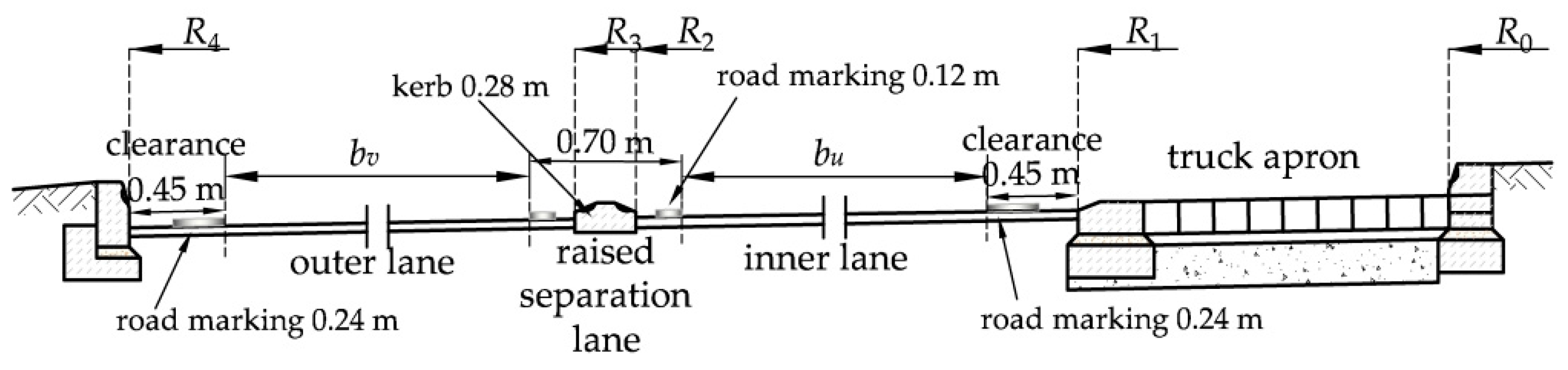
| Main Elements of a Transverse Cross-Section of the Roundabout | Mathematical Designation | Radius and Measurement in m |
|---|---|---|
| Fastest path speed for a passenger car in km/h | v | 40 |
| Radii | ||
| Inner radius of the inner lane | R1 | 20.00 |
| Outside radius of the inner lane | R2 | 24.90 1 |
| Inner radius of the outside lane | R3 | 25.20 2 |
| Outside radius of the outside lane | R4 | 29.90 |
| Curve lane divider entry | Rt | 12 |
| Curve lane divider exit | Ra | 14 |
| Widths | ||
| Overrun area (truck apron) width (R1 − R0) | 5.00 | |
| Raised separation lane between driving lanes | 0.70 | |
| Width, inside lane | bu | 4.25 |
| Width, outside lane | bv | 4.05 |
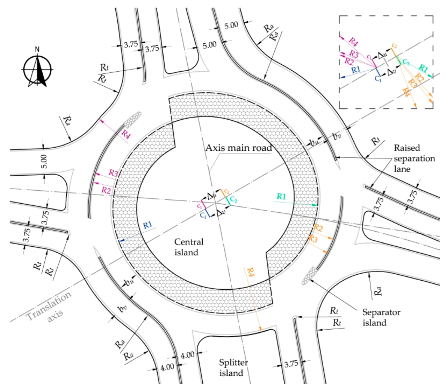
| Shift of inner arc centres along the translation axis (stakeout: R2, R3, R4) | ∆v | 5.15 |
| Shift of outer arc centres along the translation axis (stakeout: R0, R1) | ∆u | 4.75 |
| Approach | Volume of Traffic by Vehicle Category, veh./h | |||||
|---|---|---|---|---|---|---|
| O | D | C | CP | A | Ap | |
| North | 683 | 28 | – | 2 | – | 22 |
| South | 683 | 28 | – | 2 | – | 22 |
| Western | 441 | 80 | 4 | 5 | 7 | 18 |
| Eastern | 630 | 19 | 8 | 5 | 7 | 18 |
| Design Vehicle Data | Vehicle Details | |||||||||
|---|---|---|---|---|---|---|---|---|---|---|
| L | MWTA 1 | MABS 2 | F | WB | B | WB2 | B2 | H | F2 | |
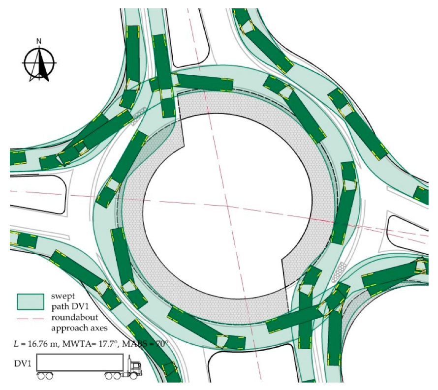
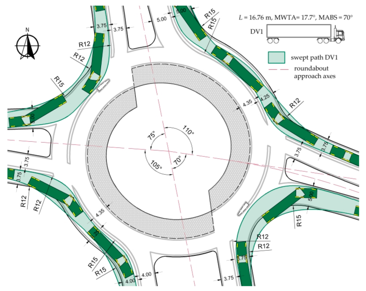
DV1  | 16.76 | 17.7 | 70 | 0.91 | 3.81 | 1 | 10.82 | 1.22 | 0 | 0.91 |
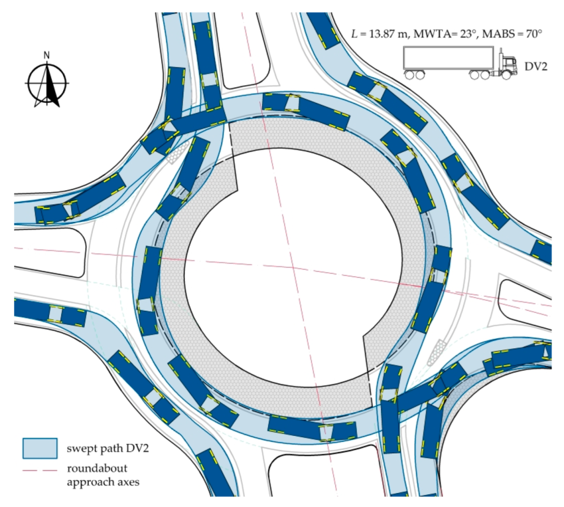
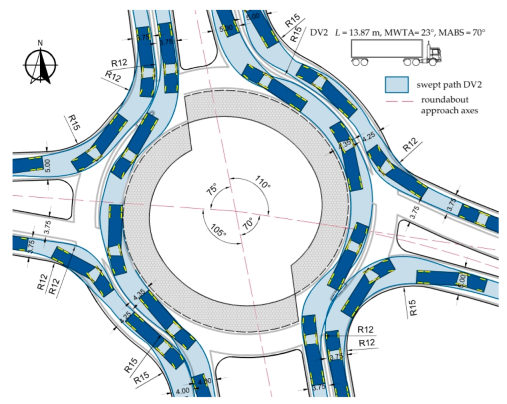
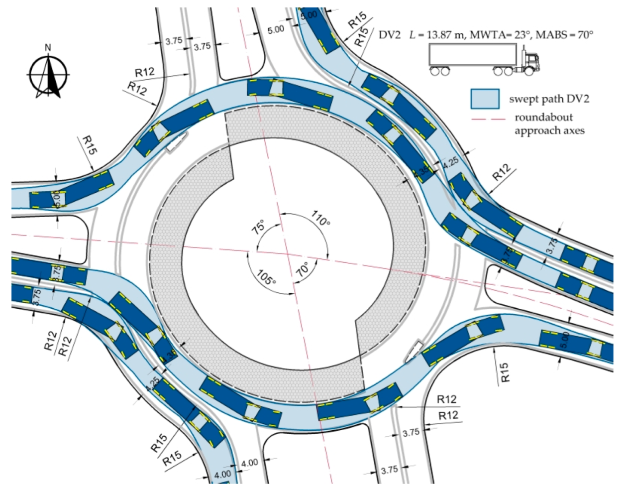
DV2  | 13.87 | 20.3 | 70 | 0.91 | 3.81 | 1 | 7.7 | 1.45 | 0 | 0.91 |
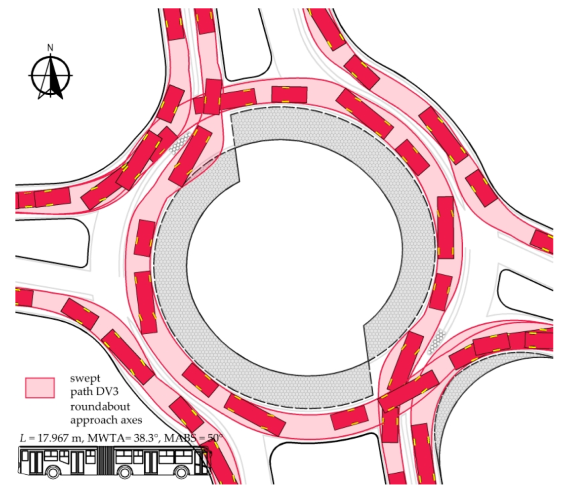
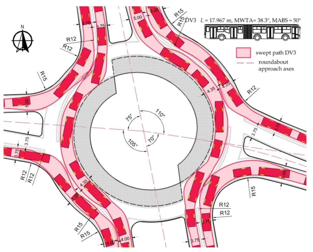
DV3  | 17.967 | 38.3 | 50 | 2.65 | 5.95 | 1.2 | 2.997 | 3.37 | 3 | 0.8 |
| Main Elements of a Transverse Cross-Section of the Roundabout | Mathematical Designation | Radius and Measurement in m |
|---|---|---|
| Radii | ||
| Outside radius of the inner lane | R2 | 25.10 |
| Inner radius of the outside lane | R3 | 25.40 |
| Outside radius of the outside lane | R4 | 30.20 |
| Curve lane divider entry | Rt | 12 or 14 |
| Curve lane divider exit | Ra | 16 |
| Widths | ||
| Width, inside lane | bu | 4.35 |
| Width, outside lane | bv | 4.55 |
| Main Elements of a Transverse Cross-Section of the Roundabout | Mathematical Designation | Radius and with Measurement in m |
|---|---|---|
| Radii | ||
| Outside radius of the outside lane | R4 | 31.35 |
| Curve lane divider entry | Rt | 14, 22, 25 1 |
| Curve lane divider exit | Ra | 16, 28 2 |
| Radius of raised separation lane at entry | 22, 25 3 | |
| Radius of raised separation lane at exit | 28 4 | |
| Widths | ||
| Width, outside lane | bv | 5.30 5 |
| Location | Feature (Radii: R1, R2, R3 and R4—see Figure 3) | Measurement in m |
|---|---|---|
| Inner lane, entry from the main approaches | RI = R1 1 + 0.45 2 + 1.5 = 20.00 + 0.45 2 + 1.5 | 21.95 |
| RII = R2 3 − 0.21 4 − 1.5 = 25.10 − 0.21 − 1.5 | 23.39 | |
| Outer lane, entry from the main approaches | RIII = R3 5 + 0.21 4 + 1.5 = 25.40 + 0.21 + 1.5 | 27.11 |
| RIV = R4 6 − 0.45 7 − 1.5 = 31.35 − 0.45 − 1.5 | 29.40 | |
| Inner lane, entry from the side approaches | RV = R1 1 + ∆v 8 + 0.45 2 + 1.5 = 20.00 + 5.15 + 0.45 + 1.5 | 27.10 |
Disclaimer/Publisher’s Note: The statements, opinions and data contained in all publications are solely those of the individual author(s) and contributor(s) and not of MDPI and/or the editor(s). MDPI and/or the editor(s) disclaim responsibility for any injury to people or property resulting from any ideas, methods, instructions or products referred to in the content. |
© 2023 by the authors. Licensee MDPI, Basel, Switzerland. This article is an open access article distributed under the terms and conditions of the Creative Commons Attribution (CC BY) license (https://creativecommons.org/licenses/by/4.0/).
Share and Cite
Sołowczuk, A.B.; Benedysiuk, W. Design of Turbo-Roundabouts Based on the Rules of Vehicle Movement Geometry on Curvilinear Approaches. Sustainability 2023, 15, 13882. https://doi.org/10.3390/su151813882
Sołowczuk AB, Benedysiuk W. Design of Turbo-Roundabouts Based on the Rules of Vehicle Movement Geometry on Curvilinear Approaches. Sustainability. 2023; 15(18):13882. https://doi.org/10.3390/su151813882
Chicago/Turabian StyleSołowczuk, Alicja Barbara, and Weronika Benedysiuk. 2023. "Design of Turbo-Roundabouts Based on the Rules of Vehicle Movement Geometry on Curvilinear Approaches" Sustainability 15, no. 18: 13882. https://doi.org/10.3390/su151813882
APA StyleSołowczuk, A. B., & Benedysiuk, W. (2023). Design of Turbo-Roundabouts Based on the Rules of Vehicle Movement Geometry on Curvilinear Approaches. Sustainability, 15(18), 13882. https://doi.org/10.3390/su151813882