Abstract
The development of automotive components with reduced greenhouse gas (GHG) emissions is needed to reduce overall vehicle emissions. Life Cycle Engineering (LCE) based on Life Cycle Assessment (LCA) supports this by providing holistic information and improvement potentials regarding eco-efficient products. Key factors influencing LCAs of automotive components, such as material production, will change in the future. First approaches for integrating future scenarios for these key factors into LCE already exist, but they only consider a limited number of parameters and scenarios. This work aims to develop a method that can be practically applied in the industry for integrating prospective LCAs (pLCA) into the LCE of automotive components, considering relevant parameters and consistent scenarios. Therefore, pLCA methods are further developed to investigate the influence of future scenarios on the GHG emissions of automotive components. The practical application is demonstrated for a vehicle component with different design options. This paper shows that different development paths of the foreground and background system can shift the ecological optimum of design alternatives. Therefore, future pathways of relevant parameters must be considered comprehensively to reduce GHG emissions of future vehicles. This work contributes to the methodological and practical integration of pLCA into automotive development processes and provides quantitative results.
1. Introduction
To achieve the goals of the Paris Climate Agreement and to comply with resulting legislation such as the European Climate Law, significant reductions in greenhouse gas (GHG) emissions are necessary [1]. In addition, increasing customer and financial market requirements regarding environmental sustainability as well as rising energy and raw material prices make sustainable products and production processes an economic success factor for companies [2]. The transport and industrial sectors accounted for 15% (8.7 Gt CO2 eq) and 24% (14 Gt CO2 eq) of the global GHG emissions, respectively, in 2019 [3]. As the automotive industry is an important part of both sectors, the reduction of the global warming potential (GWP) of vehicles plays an increasingly important role in the development of future cars [4]. Original equipment manufacturers set ambitious targets to decrease the GWP of their products which can be seen, among other things, in the transition from internal combustion engines to battery electric vehicles (BEV) aiming to decrease GHG emissions during vehicle usage. Subsequently, the production process of BEVs plays a crucial role when considering the complete life cycle of a car. In addition to the production of the traction battery, which accounts for a large share of total vehicle emissions, the production of structural components in the body and chassis also contributes significantly and needs to be decarbonized [5].
During the use stage of BEVs, the GHG emissions are mainly influenced by the energy demand of the vehicle and the emission intensity of the electricity mix used for the charging of the vehicle [6]. The energy demand and with this the GHG emissions are influenced through the vehicle’s weight [7]. A lightweight design is established in the automotive industry to reduce the mass of vehicle components and the associated energy demand of the complete vehicle. The leverage of the lightweight design to directly reduce energy demand depends mainly, but not exclusively, on the vehicle powertrain and its efficiency [8]. Due to the higher powertrain efficiency and recuperation of BEVs, the influence of a lightweight design on the vehicle energy demand is usually lower compared to vehicles with internal combustion engines (ICEV) [9]. A measure to quantify the change in energy demand as a result of lightweight design is the fuel reduction value (FRV for ICEV) or energy reduction value (ERV for BEV) [8]. Depending on the driving cycle and the vehicle type, energy saving potentials of up to 39.2 kWh for ICEVs and 23.4 kWh for BEVs per kilogram of mass reduction result over a typical vehicle use stage of 200,000 km, assuming FRV and ERV values provided in Kim and Wallington [9] and Del Pero et al. [10]. In addition to direct reductions in energy demand, the reduction of vehicle mass through lightweight design offers the possibility of achieving secondary mass effects that can additionally reduce energy demand and associated GHG emissions. This includes, for example, the downsizing of powertrain components without reducing performance, as well as a downsizing of the battery in BEVs without reducing the range [6,8]. Moreover, the lightweight design can increase material efficiency by using less but higher strength materials [11]. A lightweight design thus offers a lever for reducing the environmental impact of vehicles, also against the background of the technology shift towards BEVs. However, lightweight materials and the underlying production processes are often associated with higher energy consumption and GHG emissions compared to conventional materials [12]. The production of primary aluminum, for example, is associated with higher GHG emissions compared to conventional steel due to direct emissions and high energy demand during the production process [13,14]. The same applies for lightweight carbon fiber-reinforced plastics (CFRP), where high energy demands during the production of the carbon fiber lead to higher GHG emissions [15,16,17]. Due to these opposing effects, different lightweight design options must be compared holistically to identify the alternative with the lowest environmental impact.
Life cycle assessment (LCA) based on ISO 14040 [18] is an established methodology in the automotive industry and many other fields, and allows a holistic quantification and analysis of the environmental impacts of a product system considering its whole life cycle. Based on LCA, Hauschild et al. have developed a framework for life cycle engineering (LCE) where LCE is defined as “sustainable-oriented product development activities within the scope of one to several product life cycles” [19]. In the past years, many methods and tools have been developed in the field of LCE that support the development of eco-efficient products. These methods and tools allow the consideration of environmental impacts and possible mitigation options during the product development process with the aim to reduce the total environmental impact of a product while respecting planetary boundaries (e.g., a finite budget of GHG emissions) [19,20]. One typical application of LCE is the comparison of environmental impacts of different design options during the product development based on LCA.
Even though tools for the integration of LCE in product development exist, the practical application of LCE in product development is not yet established due to several challenges. Cerdas [21] groups these challenges in three categories: (1) methodological challenges, e.g., related to the complexity of the product system and the method itself, (2) applicability challenges often related to the time and resource intensity of the data collection process, and (3) interpretability challenges due to complex and uncertain results. One central issue towards the implementation of LCE in product development is that results of conventional LCAs, which are used in LCE methods, only provide retrospective information regarding the environmental impacts as the used databases contain past datasets [22]. This can be problematic given the time frame of a vehicle development and usage: between the start of the development process and the start of the series production of a vehicle component, there is a time gap of approximately three to five years [23]. In the case of radical material innovations, this can be even significantly higher. If the production period of a vehicle model series (approximately 7 years [23]) and use stage of a vehicle until its disposal (10 years and more) are also considered, this results in a time gap of more than 20 years. In the meantime, changes in production processes [24,25], changes in energy or material supply [26,27,28,29,30,31], or changes in use stage emissions, for example, through changes in the electricity grid mix [26,31,32], can have significant effects on environmental impacts. The integration of conventional LCAs in the product development phase of vehicle components, therefore, does not reflect their actual environmental impacts during production and use. This can lead to wrong decisions, for example in material selection. The integration of future-oriented LCAs within LCE is a possible option to overcome this hurdle.
In the field of future-oriented LCAs, numerous terms are used, but so far no consistent distinction has been established, as analyzed in detail by Buyle et al. [33]. The term prospective LCA (pLCA) is regularly used in literature and will be used in the context of future-oriented LCAs in this paper. PLCA is a method for estimating future environmental impacts of an object under study [22]. It is not a method to predict the future, but it allows us to explore possible future developments and to include these in the decision-making process. Even though pLCA has gained a strong momentum in current research, a methodology to practically integrate pLCA in the development process of automotive components has not been introduced so far. This is because, in addition to the challenges already described in the application of LCE, the application of pLCA suffers from challenges concerning the modeling of future product systems due to the fact that the future is inherently uncertain (epistemological uncertainty) [34]. A more detailed description of the current state of research in the field of pLCA is provided in Section 2.2.
In Ostermann et al., we have presented the methodical basis for integrating pLCA into the development process of lightweight components [35]. It is shown that the consideration of future development paths of relevant parameters can lead to a shift of the ecological optimum in a comparative LCA study. While future developments of all parameters identified as relevant are taken into account, the future development is limited to the consideration of only one best-case scenario. A consideration of less optimistic but realistic scenarios is excluded. This, in turn, would considerably increase the space of parameter projections and combinations which do not always have to be consistent with each other. To deal with the increased complexity, an extension of the methodology presented in Ostermann et al. is required.
The aim of this paper is therefore to further develop a methodology that enables the implementation of pLCA in the development process of automotive products by linking pLCA with LCE, considering all relevant LCA parameters and any number of future scenarios. In Section 2 of this paper, the state of research in the fields of LCE and pLCA is presented. Section 3 introduces the developed methodology for the integration of pLCA in LCE. Section 4 shows the application of the methodology on the case study of an automotive lightweight component based on industry data. Section 5 discusses the findings and gives an outlook on future work. Finally, Section 6 summarizes the conclusions of the paper.
2. State of Research
2.1. LCE of Automotive Components
LCE methods are used in the product development of cars to reduce the environmental impact of the product over the complete life cycle by considering impacts from the extraction of raw materials, the production of the car, the use stage and the recycling of the car [12]. On the overarching level of the complete vehicle development, for example, Broch [36] developed a concept to integrate life-cycle-based environmental assessment already in the early development of new vehicles with the help of parameterized life cycle inventory models from the perspective of an automotive OEM. During the development process of a complete vehicle, technical and environmental vehicle targets are broken down to component targets and specifications [37]. The detailed technical development that usually takes place on the component level is often carried out by automotive suppliers and influences the environmental impact of the complete car. In the component development, LCE supports the development of components with reduced environmental impacts. One component with a significant environmental impact is the traction battery of a BEV. With the concept of integrated computational life cycle engineering (ICLCE), Cerdas [21] has analyzed the effects of temporal, geographical and technological/behavioral aspects of variability on the application of batteries for electric vehicles. Furthermore, Von Drachenfels et al. [38] have developed a novel LCE approach that uses modular material and energy flow models to assess product and process innovations.
Besides the battery, the structural components of a car have a significant environmental impact. Here, LCE can be applied to asses and improve the eco-efficiency of lightweight automotive components [12]. Lightweight components are of special interest as opposing effects in the production and the use stage complicate the decision of whether a lightweight component is environmentally friendly or not. To support decision making towards the development of eco-efficient automotive components, several studies have introduced approaches towards the integration of LCE in the (lightweight) component design [4,37,39] and a general framework on LCE of lightweight components was developed by Herrmann et al. [12] following the LCA methodology according to ISO 14040 [18]. Kaluza et al. [37] have analyzed crucial decision points for the integration of LCE in the component development process and conclude that an integrated assessment of environmental, technical and economic performance is a key requirement for LCE. Such an integrated method, the concurrent engineering approach, was developed by Kaluza et al. [39], where life cycle engineering is a parallel working stream to the technical component design. Within this approach, regular information exchanges between the working streams and a joint decision-making process with the participation of both work streams are proposed. Based on this and the LCE framework, Reimers et al. [4] have developed a method that integrates LCE in the conceptual design of automotive body components and allows designers to assess different design options in terms of their GWP. The method considers different parameters affecting the GWP of body components such as different material yields, markets (for materials or electricity) and mobility concepts (e.g., different drivetrain technologies). The presented LCE methods and tools can be called “prospective”, as they try to anticipate environmental impacts of a product already in its development process. However, the methods do not consider future aspects such as changing production efficiencies or changes in the material production consistently by introducing scenarios for the fore- and background system. It is rather the variation of individual parameters that is analyzed to determine possible future effects on the system.
2.2. Prospective LCA
PLCA as defined by Arvidsson et al. refers to “studies of emerging technologies in early development stages, when there are still opportunities to use environmental guidance for major alterations. In order to capture the potential future environmental impacts of a technology in such cases, the system modeled is placed in a more distant future” [22]. However, the application of pLCA is not limited to emerging technologies. Figure 1 shows possible applications and use cases of pLCA as identified by Buyle et al. [33] and Mendoza Beltran et al. [32]. As shown pLCA can be applied to assess technology development, technological learning and technology diffusion in the foreground and background systems. By combining developments in the fore- and background system, pLCA can support decision making in several areas such as future technologies or production systems.
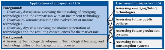
Figure 1.
Applications and scopes of prospective LCA studies (left side of the figure based on Buyle et al. [33], right side based on Mendoza Beltran et al. [32]).
The aim of pLCA is the consideration of long-term changes in the foreground and background system of the product under study. Scenarios are an effective way to consider these long-term changes [22]. A framework for the usage of scenarios in LCA was introduced by Fukushima and Hirao [40] and is shown in Figure 2. The so-called scenario development consists of two steps, the scenario generation and the scenario evaluation. In the first step, the scenario generation, different future scenarios for the system under study are generated using techniques like forecasting and back-casting. The scenarios can affect the life cycle inventory (LCI) by changing in- and output flows of the processes used and the life cycle impact assessment (LCIA) by changing the LCIA model for the calculation of a GWP. In the second step, the scenario evaluation, the generated scenarios are assessed by calculating the environmental impacts of the scenarios on the studied system.
One major challenge during scenario generation is the identification and quantification of possible future scenarios. The recent research shows a wide range of methods and techniques that have been used to generate scenarios. Arvidsson et al. [22] and Thonemann et al. [41] summarized a number of possible methods that can be used to support scenario generation for pLCA. Existing methods were also analyzed by Buyle et al. [33] in their literature review to show for which applications of pLCA which methods are used. Based on these studies, the typical methods are participatory methods, learning curves, extrapolations, or the usage of ideal systems. Furthermore, literature findings and our own assumptions are always an additional possibility to generate scenarios.
Besides the usage of future scenarios in pLCA, scenarios are also established in other scientific fields. Using additional methods from these fields can help to overcome the challenges addressed above. In the context of strategic product planning, for example, the scenario technique is used to identify future potentials for companies’ business models or product portfolios. The scenario technique developed by Gausemeier et al. [42] is shown parallel to the scenario development by Fukushima and Hirao [40] in Figure 2 as both approaches show similarities even if they originate from different scientific fields. Compared to the scenario generation step in the scenario development framework, the scenario technique describes a more detailed and structured approach. The scenario technique comprises five steps. In the first step, the scenario preparation, the scope or decision field of the scenario study is defined. Based on this, the scenario field-analysis identifies the most relevant influence factors on the decision field (key factors). For each key factor, possible future developments, called projections, are developed in the scenario prognostic and then combined into consistent projection bundles. These projection bundles form different future scenarios during the scenario building. The final step of the scenario technique, the scenario transfer, analyses the impact of the scenarios on the decision field and is similar to the scenario evaluation step of the scenario development framework by Fukushima and Hirao. Parts of the scenario technique have already been used in the field of pLCA. Spielmann et al. [43], for example, have developed an approach for scenario modelling in pLCA based on the formative scenario analysis that uses consistency analysis according to step four of the scenario technique.


Figure 2.
Two frameworks for the usage of scenarios in context: Framework for scenarios in LCA by Fukushima and Hirao [40] (top) and scenario technique by Gausemeier et al. [42] (bottom).
Figure 2.
Two frameworks for the usage of scenarios in context: Framework for scenarios in LCA by Fukushima and Hirao [40] (top) and scenario technique by Gausemeier et al. [42] (bottom).
In more recent literature, the concept of using existing scenarios for the usage in LCA has gained attention. One research result is the usage of scenarios from integrated assessment models (IAMs) in the context of future background databases for pLCA. IAMs provide interdisciplinary insights about human and natural earth systems and are defined by Edmonds et al. as “a class of models which simulate the interactions of human decision-making about energy systems and land use with biogeochemistry and the natural Earth system” [44]. Mendoza Beltran et al. [32] have shown how scenarios from IAM can be used to modify the ecoinvent database [45] to use it as a background database for pLCA studies. Based on this approach, Sacchi et al. [46] developed the Python library Premise that allows a relatively simple modification of ecoinvent with the IAMs IMAGE [47] and REMIND [48]. With the tools from this library, different future versions of ecoinvent can be built that represent different future scenarios at different times. These future versions of ecoinvent can be used as background databases for pLCA. As the usage of multiple background databases to assess different scenarios can be complicated and resource intensive when using the Python package Brightway2 [49] for LCA calculations, the superstructure approach was developed by Steubing and Koning [50]. This approach combines different future databases to one single LCI database and simplifies the application of multiple scenarios in LCA.
The approaches and tools have already been applied to some case studies. Cox et al. [51] use future versions of ecoinvent with modified electricity grid mixes based on the IAM IMAGE to assess future environmental impacts and the total cost of ownership for different powertrain configurations. A case study on hydrogen production with water electrolysis combines scenarios in the foreground and background system to assess future environmental impacts of the hydrogen production as an example for an emerging technology [52]. In this study, Schropp et al. [52] use IAM scenarios to change their background system. To develop different scenarios for the foreground system, the general morphological analysis (GMA) described by Ritchey [53] is used. The development of future scenarios for the foreground system based on GMA is also used by Delpierre et al. [54] in their study on future environmental impacts of wind-based hydrogen production. The introduced examples focus on the evaluation of emerging technologies such as hydrogen production or battery electric vehicles with focus on for example informing policy makers. However, they do not focus on the integration of pLCA in component development for vehicles.
2.3. Integration of pLCA in LCE of Automotive Components
The literature review shows that the integration of pLCA in LCE of automotive components has not been established until now. However, it has the potential to improve decision-making on how a product should be designed or produced to be environmentally friendly in the future [35,55]. Dér et al., for example, use elements of pLCA to analyze future potentials of fiber-reinforced lightweight body parts for the application in the automotive industry in comparison to steel and aluminum [55]. In their study the GWP of the electricity generation as well as some production specific parameters (e.g., material intensity) are changed in two different future scenarios. The study shows that the application of fiber-reinforced body parts can have advantages in future vehicles with very long use stages. However, the study does not introduce an approach to explore a wider variety of future scenarios and does not include changes in the materials GWP. Material production, however, is responsible for a significant share of a typical automotive and can undergo significant changes in the future as we observed in our previous paper [35].
3. Materials and Methods
As shown in Section 2.1, the existing literature already provides methods to include LCA-based LCE in the development of components. Furthermore, the field of pLCA consists of several methods to allow the integration of future perspectives in LCA (Section 2.2). However, a consistent methodology to implement several possible future developments in design decisions of automotive components within LCE for the practical application in the industry is not available. Changes in future electricity mixes can already be considered by using Premise and a future ecoinvent version [46]. However, the use of new technologies for the raw material production, such as the steelmaking via the hydrogen based direct reduction route, is not yet included in future versions of ecoinvent generated with Premise.
We have provided a first methodical basis for the integration of future scenarios in the development process for automotive components that includes changes in the foreground and background system in Ostermann et al. [35]. Using a crash management system (CMS) as an example, the study used future projections to show that significant changes in GWP are possible over time. Future projections from different sources were combined to analyze future developments of parameters previously identified as relevant, such as the generation of the electricity used, the production of raw materials and the component production itself. However, the study only provided one single future scenario and did not consider the wide range of possible future scenarios as the methodology lacks a structured approach for the identification of consistent future scenarios considering a variety of projections of each parameter. Using the findings from Section 2.1 and Section 2.2, we have therefore further developed the methodology of Ostermann et al. [35] with a focus on practical application in the automotive supply industry by (1) further detailing it with respect to the generation of consistent scenarios and (2) integrating it into the LCE framework for LCE for lightweight components proposed by Herrmann et al. [12]. The proposed methodology combines the typical elements of traditional scenario technique [42] and scenario usage in LCA [40] with the possibilities from new available tools to develop new background databases [32,46,51].
Methodology for Application of Prospective LCA in LCE of Automotive Components
Figure 3 shows the structure of the developed methodology that follows the five methodological phases of LCA-based LCE and integrates scenario development as a key element of pLCA. The phases of conventional LCE are described in detail in Herrmann et al. [12]. In this paper, we focus only on the new elements of the methodology originating from the integration of pLCA in LCE. The methodology can be understood as an iterative approach that passes through the first four phases of the LCE framework: goal and scope definition, life cycle inventory data gathering, life cycle impact assessment, and interpretation and visualization. Initially, this is carried out for one or several reference products for the present and with conventional foreground and background data. This first initial LCA of a reference product serves as the starting point for the pLCA in the LCE context where all five phases of the LCE framework are passed through. From the (1) goal and scope definition of the initial LCA, the definition of the products under study and the definition of the foreground and background system are already defined. For the pLCA, the goal of the prospective study, the possible future scenarios considered, and the future product models resulting from these scenarios must additionally be defined. Furthermore, the effect of the considered future scenarios on the (2) life cycle inventory data for the foreground and background system must be evaluated. Both, the definition of a future product model with its foreground and background system and the future life cycle inventory data are established through the scenario generation.
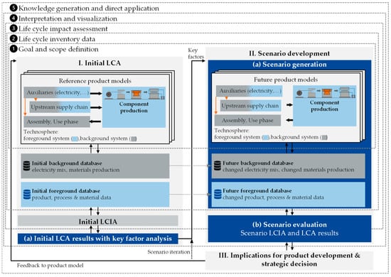
Figure 3.
Methodology for integration of pLCA in the LCE framework based on Herrmann [12], Fukushima and Hirao [40] and Ostermann et al. [35].
In the (3) life cycle impact assessment (LCIA) of the future product models, the elementary flows from the future life cycle inventory are connected to characterization factors that quantify the environmental impacts of the elementary flows in different impact categories such as the global warming potential (GWP). The results of the LCIA are further analyzed in the (4) interpretation and visualization phase and put into context with the system under study. It is important to interpret and visualize the results in a way that allows decision-makers to use the result in the last phase, the (5) knowledge generation and direct application. This last phase is the key element that differentiates LCA from LCE as the LCA results are directly used to find implications for the product development and strategic decision-making with the goal to optimize the environmental performance for the product under study [12]. The results gathered from the pLCA of the product for different possible future scenarios enrich the result compared to conventional LCE, as they allow us to consider possible future changes in the foreground and background system, thus deriving new implications for the product development and strategic decision-making. Examples are the influence of design decisions early in the development phase or the adaptation of R&D roadmaps due to observations made for future scenarios.
The decisive new aspect of the proposed methodology is the development of consistent future scenarios for the system under study considering a variety of projections of each key factor. Methodological details for the identification and evaluation of future scenarios are shown in Figure 4. Based on the first step, the initial LCA (I), the product under study is analyzed to identify important impact factors in the key factor analysis (I-a). Conventional LCA is used here to identify the biggest influence factors in the foreground system and the background system by performing a contribution analysis on different levels from the perspective of a component producer:
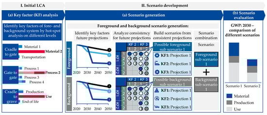
Figure 4.
Detailed description of the key factor analysis of the initial LCA and the scenario generation and evaluation steps of the scenario development.
- Cradle-to-Grave: Considering the whole product life cycle to identify general hot spots in the foreground and background systems.
- Gate-to-Gate: Considering the component production at the component producer to identify production processes with high GWP (foreground system).
- Cradle-to-Gate: Considering the upstream supply chain to analyze the contribution of materials and auxiliaries used (background system).
In the second step, the scenario development (II), scenario generation (II-a) provides future scenarios for the product under study, which are subsequently evaluated in scenario evaluation (II-b). The scenario generation step is performed separately for the foreground and the background system to allow a separate assessment of foreground key factors with a high level of influence by the producing company and background key factors that are mainly influenced externally. First, future projections are developed for each key factor identified through the key factor analysis. Possible future projections can be identified by using existing projections from literature, especially for widely used materials and processes in the background system. One possible source for the identification of projections in the background system is by using the Premise library in Python to build future versions of the ecoinvent database. For the foreground system that can contain unique or very company specific processes, our own projections must be developed. The same applies for new or emerging technologies that are part of the product system. For all key factors, where projections are not available from the literature, the methods described in Section 2.2 can be used.
Second, the developed future projections need to be analyzed concerning their consistency with each other to define consistent scenarios for the foreground and the background system. This can be carried out by using a consistency matrix, where a pairwise comparison for each projection pair is performed [42].
Third, the consistency matrix is evaluated to find the most consistent bundles of projections. Depending on the number of key factors and projections, the consistency calculation of every possible projection bundle can be very time consuming. Algorithms have been developed to optimize the assessment of the consistency matrix. One example that can be applied in this step is the usage of evolutionary algorithms in the context of consistency analysis as described by Grienitz and Schmidt [56]. Even after the consistency analysis, there can be many possible projection bundles with a high consistency. Analyzing every single projection bundle would not be efficient and would also not provide additional value. Some projection bundles are very similar as, for example, only one projection for one key factor is different. To reduce the number of projection bundles, these similar bundles can be grouped with the help of clustering algorithms such as agglomerative clustering forming a manageable number of scenarios [42].
Fourth, after the scenarios for the foreground and background system have been identified, the foreground and background scenarios are combined to scenarios for the whole product system. Again, consistency analysis can support the combination here. Depending on the number of developed scenarios, the combination can be performed manually or with a consistency matrix. For the final scenarios, LCI databases for the foreground and background system are created based on the projections for each key factor in the scenario.
In scenario evaluation (II-b), the developed future scenarios are evaluated by following the steps of a typical LCA based on the generated future LCI databases. Depending on the scope of the study, only one future year or several future years can be assessed to show the development over time. The results of the scenario evaluation can be used in a third step to derive implications for product developments and strategic decisions (III). These implications can be used to apply changes to the original product.
4. Results—Case Study
The proposed methodology is applied to the automotive component of a front crash management system (CMS) in three different material designs that also served as a case study in our previous paper [35] to provide exemplary results of a pLCA in the context of LCE and show the practical applicability of the methodology.
4.1. Goal and Scope Definition
The goal of this case study is to determine which of the material designs perform best in terms of environmental impact under different possible future scenarios, in order to answer the question of how the selection of a material design can support decarbonization, taking into account future developments. The study covers a time horizon of 30 years with 2020 serving as a base year for the scenarios developed. As decarbonization is the main aim of the study, the impact category climate change based on the midpoint indicator GWP is considered exclusively. To calculate the GWP, the LCIA method of the International Panel on Climate Change (IPCC) from 2013 (assessment report 5) with a timeframe of 100 years is used. We are aware that changes that allow mitigating climate change can influence other impact categories negatively, as shown, for example, in Schropp et al. for the increased resource depletion potential for minerals and metals through the usage of renewable energy sources [52].
The general function of a CMS is to absorb crash energy in the event of a frontal crash to reduce the impact of the crash on the passengers and to avoid damage to structures behind at low crash velocities [57]. Considering this, the functional unit of this study is a CMS that fulfills predefined crash requirements. The reference design is a state-of-the-art steel design containing high strength press-hardened steel. Two alternative designs have been developed based on finite element simulations of common crash load cases to ensure equivalent mechanical properties. The aluminum design uses 7000 series high strength aluminum in the form of extrusion profiles and the hybrid design is combining steel and CFRP to form a fiber-metal laminate (FML). FMLs that combine metals and FRPs in a layered structure are already used in series production in aviation and provide increased lightweight potential due to load-adapted thickness properties [58]. Further details on the material composition and the production routes of the respective designs can be found in Ostermann et. al. [35] and in Figure A1 of Appendix A. An exemplary picture of a CMS and details on the mass of the three design alternatives are shown in Figure 5.
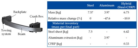
Figure 5.
Exemplary picture of a CMS [59] (left) and mass details of the three design alternatives considered in the case study from [35] (right).
4.2. Initial LCA and Key Factor Analysis
For the initial LCA, the results already presented by Osterman et al. [35] have been used as a starting point for the scenario generation. The LCA considers the production of raw materials, the processes for the component production at the component supplier and the usage of the components in a battery electric vehicle. Further production steps at the OEM are not considered due to missing data. However, it is assumed that these production steps are not material since a crash management system is typically just mounted to the rest of the car by screws. A cut-off approach is chosen for the end-of-life phase, since an equivalent shredding process with comparable GWP can be assumed for all design alternatives at the end-of-life. Due to the comparative character of the LCA, the shredding process is not further considered. For the used materials, LCI data from associations such as Worldsteel [60] and European Aluminium (EA) [61] as well as data from research literature, especially for the materials connected to the hybrid, have been used. For the component production processes, primary industry data for established processes and experimental data for the production of the hybrid components have been used. For the use stage, a mileage of 200,000 km is assumed and the electricity consumption during the use stage is estimated by using fuel reduction values according to the formula given in Ostermann et al. [35]. For the production of further auxiliaries such as compressed air and electricity generation, datasets from ecoinvent have been used. A more detailed description of used datasets can be found in Table 1.

Table 1.
Used datasets and assumptions for the initial LCA.
The result of the initial LCA is shown in Figure 6. On the left side, the emissions from input material production and the production of the component are displayed. During the production phase, the aluminum design has the highest GWP (31 kg CO2 eq.), followed by the hybrid design (28 kg CO2 eq.) and the steel design (25 kg CO2 eq.). On the right side, the emissions from the use stage are displayed assuming a linear increase in emissions over the expected lifetime of 200,000 km. During the use stage, the emissions of the aluminum and hybrid design are lower compared to the steel design due to the reduced component weight and the resulting energy savings during usage. Therefore, the higher production emissions can be partly compensated during the use stage. Considering the entire life cycle, the GWP of the aluminum design is 43 kg CO2 eq., followed by 49 kg CO2 eq. for the steel and 50 kg CO2 eq. for the hybrid design. The break-even point between the aluminum and the steel design is reached after about 101,00 km of usage. This means that higher emissions from the production stage of the aluminum design are compensated through lower use stage emissions after 101,000 km. No break-even point is reached between the hybrid design and the steel design, showing that during the considered use stage, the lightweight effect of the hybrid design is not large enough to compensate higher production emissions. The result shows that the aluminum design would be the most favorable option from today’s perspective and the given boundary conditions.
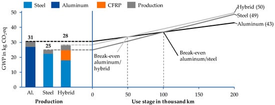
Figure 6.
Results of initial LCA from Ostermann et al. [35] for the production and use stage of all three CMS designs, showing favorable designs and possible break-even points.
Based on the initial LCA a contribution analysis for the foreground and the background system was performed. We found several key factors for the foreground system and the background system (compare Figure 7). The foreground system and background system are defined from the perspective of a component producer in the automotive supply chain. The foreground system comprises all elements of the product life cycle that can be influenced by the component producer/developer [69]. Therefore, key factors in the foreground system refer to the processes used for the component production and the energy consumption of these processes. Besides the energy consumption, the process specific material efficiency is also a relevant factor. The background system refers to all other elements of the product life cycle. The main key factors in the background system are the production of the different materials (including the usage of recycled materials in the production) as well as the usage of the vehicle and the corresponding electricity generation in all life cycle stages. The identified key factors serve as a basis for the following scenario generation.
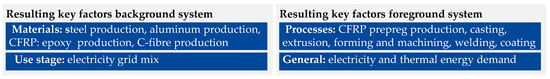
Figure 7.
Key factors for the foreground and background system resulting from the contribution analysis of the initial LCA based on Ostermann et al. [35].
4.3. Scenario Generation
The scenario generation is based on the general ideas of the scenario technique [42] as described in Section 3 and consists of the identification of future projections, consistency analysis of the future projections and the building of scenarios from consistent projection bundles. The steps are described in detail for the use case in the next three sections.
4.3.1. Identification of Future Projections
For each identified key factor, at least three possible future projections have been defined. For foreground key factors, possible future projections are developed based on expert discussions and brainstorming, as most foreground key factors are very specific and no or little literature exists on possible future developments. For background key factors, which refer to broad topics such as steel, aluminum, or carbon fiber production, the literature findings could be used to identify possible future projections. The main sources where publicly available scenarios such as scenarios for the aluminum and steel production by the International Aluminum Association (IAI), EA, and International Energy Agency (IEA) as well as scientific publications on potential improvements in carbon fiber and matrix production [15,16,17,28,30,31,62,63,70,71]. For the key factor of electricity generation, the scenarios from the IAM IMAGE have been used [47]. An excerpt of the resulting projections is shown in Figure 8. An extensive overview of all projections with a detailed description can be found in Table S1 in the Supplementary Materials based on [15,16,17,27,28,29,30,31,46,60,62,63,64,65,66,67,70,71,72,73,74,75,76,77,78,79].
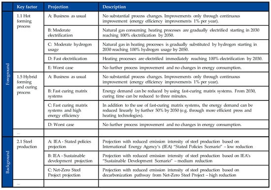
Figure 8.
Future projections for key factors in foreground and background systems (excerpt).
4.3.2. Consistency Matrix
To assess which projections are consistent with each other and can therefore be part of the same scenario, a consistency matrix for a pairwise comparison was used. Figure 9 shows an excerpt of the consistency matrix for the foreground system. The consistency of each pair of projections was rated during a workshop with the project team. The consistency was rated from 1 to 5 based on the scale defined by Gausemeier [42]. Based on this rating the consistency value C is calculated for each possible projection bundle. A bundle is a set of projections consisting of one projection from each parameter (compare Figure 9). The consistency value for one bundle is the sum of all consistency ratings in this bundle. For the foreground system 13,500 bundles were identified with a maximum consistency value of 105. The same procedure was also performed for the projections in the background system with a second consistency matrix.
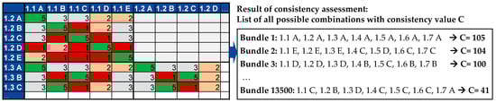
Figure 9.
Excerpt of foreground system consistency matrix (left) and possible projection bundles (right). Scale for consistency rating: 1: complete inconsistency, 2: partial inconsistency, 3: neutral or independently, 4: mutual assistance, 5: strong mutual assistance based on [42].
4.3.3. Scenario Building
To obtain a useful number of scenarios that can be evaluated, the identified projection bundles were filtered by consistency and then clustered according to their similarity. To ensure that only highly consistent projection bundles are considered for scenario building, a minimal threshold for the consistency value of C ≥ 90 was defined. Furthermore, all projection bundles containing a consistency rating of 1 (complete inconsistency) were excluded. This resulted in 23 projection bundles that were clustered in a next step. For this, an agglomerative hierarchical clustering approach was used that clusters projection bundles with similar combinations of projections according to one cluster based on the Euclidean distance. For the foreground system, five clusters of similar projection bundles were identified. For each cluster, it was analyzed which projection occurs most frequently for which parameter. The most frequent projection was defined as the decisive projection. In clusters where no clear tendency emerged (e.g., same frequency of two projections for one parameter) the cluster was split. This was, for example, the case for the “Sustainable development” scenario in the background system where neither the usage of lignin fibers (projection 2.5 E) nor the usage of biobased polyacrylonitrile (PAN) as precursor (projection 2.5 D) could be clearly identified as decisive projection. Therefore, this cluster was split into two different clusters with only parameter 2.5 differing between the clusters. The resulting clusters were finally defined as foreground- or background scenarios. The resulting scenarios with their decisive projections and short descriptions are shown in Figure 10.
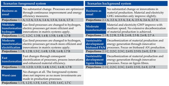
Figure 10.
Scenarios for foreground and background system.
Based on the single scenarios for the foreground and background system, combined scenarios for the complete technosphere were defined. To carry this out, the foreground and background scenarios were compared in a matrix as shown in Figure 11. In a workshop, the project team evaluated which foreground system scenarios are likely to occur with which background system and which combinations can lead to interesting results. For example, the combination of a very progressive foreground scenario (Fast transformation) with the business-as-usual scenario for the background system was rated as an unlikely scenario. The project team decided to focus on eight scenarios for further analysis.
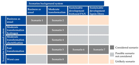
Figure 11.
Scenario matrix for simplified consistency analysis between foreground and background scenarios.
After defining the scenarios to be analyzed, the impact of these scenarios on the product model and the foreground and background databases had to be defined to create future foreground and background databases. For this, the projection bundle of each scenario was analyzed in detail and database transformation rules were defined for each parameter. The transformation rules are used to transfer the original databases for the foreground and background system (baseline 2020) to a future database in a certain future year and under a certain scenario. Figure 12 shows schematically how this conversion takes place. The transformation of the databases was carried out in Brightway2 by using the Python packages Wurst and Premise. Wurst allows the practitioner to change elements from an existing database in Brightway2 and create a new changed database. It was developed by Mendoza et al. [32]. For foreground key factors such as the hot forming process, Wurst was used to change the amount of energy used for the process or the type of energy used by shifting the energy consumption from natural gas consumption to electricity consumption depending on the chosen scenario and year. The same approach was used to change the GWP intensity of used materials according to the literature findings for future material scenarios. In parallel, Premise was used to create future ecoinvent databases that serve as background databases for the pLCA according to the transformation rules for the key factor electricity generation. By using the transformation rules, the original baseline databases were transformed to three future databases (2030, 2040 and 2050) for each of the eight scenarios, resulting in a total of 24 future foreground databases and 24 future background databases.
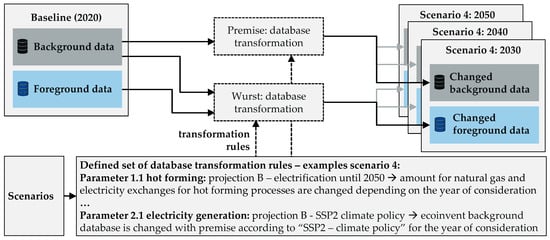
Figure 12.
Schematic illustration of the generation of future databases by transformation of the baseline databases with the Python packages Wurst and Premise.
4.3.4. Scenario Evaluation
The LCI data resulting from the scenario generation were used to calculate the future GHG emission for each design and each scenario from 2020 to 2050 in 10 years steps. The calculation was performed in Brightway2 using the LCIA method GWP (IPCC V5). The calculation results in 96 or 288 data points if different life cycle stages are evaluated separately, leading to a complex result. Cerdas et al. [80] propose the usage of heat maps to display complex results in LCA to decision makers. Following this proposal, we have customized the heat map to the scope of this study to display the GWP of each product and scenario over time with the help of a cluster heat map in Figure 13. The figure shows the GHG emission intensity separately for the life cycle stages cradle-to-gate, gate-to-gate and the cradle-to-grave. The cradle-to-gate stage involves all materials used to produce the components. The gate-to-gate stage includes the production processes and the production of auxiliaries and energy used for these processes. The cradle-to-grave perspective shows the whole life cycle including the use stage of the components in a BEV. The emission intensity is displayed using three hues with red representing the highest GWP and green representing the lowest GWP. In addition to the eight scenarios (S1–8) that have been developed in this paper, the initial scenario (S0) presented by Ostermann et al. [35] is also displayed in the graph to compare the results. The graph in Figure 13 allows several conclusions that can support decision making during product development. Some exemplary conclusions are summarized in the next sections.
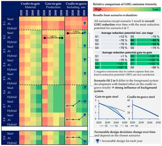
Figure 13.
Heat map with a relative comparison of future development of GHG emissions for scenarios S1–S8 in comparison to S0.
Different scenarios show different GWP reduction potentials concerning the intensity of the reduction and the speed of reduction. Scenario 1 is the only scenario not resulting in an overall decline of the GWP connected to the analyzed design alternatives for the complete life cycle including the use stage. This is mainly since the business-as-usual scenario for the background system results in an overall increase in GWP connected to the electricity generation due to the usage of the SSP2 baseline scenario from the IAM IMAGE. This development overweighs the energy efficiency measures that are assumed in the production processes over time for all three material designs. All other scenarios result in an overall decline of the GWP of up to 92% averaged over all design alternatives.
The left graph in Figure 14 shows a more detailed comparison of reduction potentials for scenarios 3 to 6 from a cradle-to-grave perspective. Scenarios 3, 4 and 5 result in similar emissions due to only limited changes in the foreground system that are overweighted by the same developments in the background system (overlapping lines for scenarios 3, 4 and 5 in the left graph of Figure 14). Scenario 6, however, shows a significant faster decarbonization and a higher overall reduction until 2050. As scenario 5 and 6 consist of the same scenario for the foreground system, the high influence of the background system becomes evident in this figure. A similar observation can be made from a gate-to-gate perspective shown on the right graph in Figure 14. Only slight differences are seen between scenarios 3, 4 and 5 even though different decarbonization strategies for the production processes in the foreground system are assumed. However, a significant change occurs in scenario 6 due to changes in the background system compared to scenario 5.
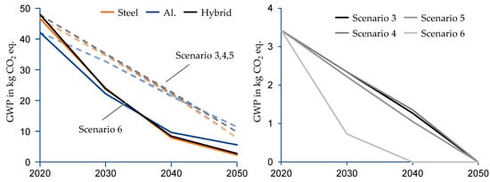
Figure 14.
(Left): Comparison of scenarios 3 to 6 from a cradle-to-grave perspective for steel, aluminum and hybrid design. (Right): Gate-to-gate perspective for hybrid design comparing scenario 3 (moderate transformation hydrogen), scenario 4 (moderate transformation electrification), and scenarios 5 and 6 (fast electrification).
Furthermore Figure 13 shows how the consideration of different future scenarios results in different proposals for favorable design decisions compared to the scenario assumed by Ostermann et al. [35]. Even though for all scenarios the aluminum version is the most favorable design in 2020, different developments can be seen for each scenario over time. For scenario 6, for example, the aluminum design is the most favorable concerning the GWP in 2020 and 2030. In 2040 and 2050, this picture changes towards the steel design, with little difference to the hybrid. In scenario 8, the aluminum design is the most favorable until 2040, and the steel design is the most favorable in 2050. The same applies for scenarios 2 to 5. Both the steel and the hybrid design show the highest relative reduction potential of 95% for steel and 94% for the hybrid design between 2020 and 2050. However, compared to the results in our earlier study, the reductions in the hybrid design are not sufficient to achieve the hybrid design being the most favorable in 2050. The reason for this is that, compared to the earlier study, no negative emissions are considered for carbon fiber production in this paper. Although, according to Hohmann [70], it is possible to produce carbon fibers with negative GWP. Therefore, the value for the best-case scenario is set to zero to avoid false conclusions such as the use of more material to reduce the GWP.
4.4. Implications for Product Development and Strategic Decisions
The scenario evaluation shows that different design decisions can be made in different scenarios for the product under study. Depending on the developments in the foreground and background system, each design can be favorable towards decarbonization in the future. The results are very much dependent on the developments in the background system, especially the development of the electricity grid mix and the development of low emission material alternatives. From the perspective of a component manufacturer, this means that the development of the GWP of its product depends mainly on parameters that can only be influenced to a limited extent by the manufacturer itself. To increase the influence on the products GWP, the component manufacturer must find ways to actively influence the background system, for example, through the active procurement of low emission energy and materials. The analysis further shows that each design alternative has high potentials for a reduction of GWP over time if certain boundary conditions are fulfilled. From the analysis, possible strategic directions can be derived for the example of a component manufacturer focusing on hybrid components to ensure that these boundary conditions are met. Exemplary approaches in the areas’ own production and materials are summarized below:
- Own production: The switch from fossil energy to renewable energy is crucial to reach a reduction in GWP from a gate-to-gate perspective. However, the analysis shows that even a very fast transformation approach from, e.g., natural gas fired processes to electrification, as shown in scenario 5, does not result in a fast decarbonization. Electrification is only useful when sufficient renewable electricity is available to substitute the fossil fuels (scenario 6). Therefore, when deciding for either the electrification of processes or the substitution of fossil fuels by other fuels such as hydrogen, the availability has to be assured. One possibility is to assure availability by investing in the production of renewable electricity or green hydrogen.
- Materials: The three main aspects of material efficiency, usage of secondary materials, and usage of sustainably produced materials have been analyzed in the context of this study to reduce the GWP from the materials used in the products. The highest potential was reached in scenarios 6 and 7, where all three aspects where applied. The first aspect is material efficiency. The efficient usage of materials in the production can reduce the GWP significantly, especially when it comes to production processes with high material losses or very GHG intensive materials like FRP. The development of material efficient production technologies is therefore one central aspect for companies. The second aspect is the usage of recycled materials to produce automotive components. The recycled materials for all materials in this study have a lower GWP than the virgin materials. Aiming at a circular economy, the recycled content should therefore be increased as far as possible without losing physical properties or the weakening the crash performance of the component. The third aspect is the sustainable production of virgin materials. Due to the increasing demand for raw materials globally, not all products can be produced with secondary materials. A certain amount of virgin material is still needed. Therefore, this virgin material needs to be produced as sustainably as possible. Investments in new technologies and partnerships with suppliers of these materials are therefore possible steps for component producers.
5. Discussion
This paper provides a methodology for integrating pLCA into the development process of automotive lightweight components and proofs the applicability of the methodology for the automotive industry with a case study. The methodology (1) combines existing methods of pLCA, scenario-based LCA and scenario technique; (2) provides a specific workflow; and is (3) embedded in the LCE framework. In comparison to previous work, any number of projections for all relevant LCA parameters of the foreground and background systems can be taken into account, and are combined to form consistent scenarios [35]. The methodology enables the identification of important influencing parameters and possibilities for their optimization towards decarbonization with the aim of practical application in the industry. In addition to considering important parameters such as used materials, the electricity grid mix and energy demands of production processes, scenarios for the use of recycled materials are also considered. The methodology thus also makes it possible to evaluate circular economy approaches and potential measures in terms of their environmental impact.
The central advantage of the proposed methodology is that by considering a range of possible future scenarios for relevant LCA-influencing parameters in the development process, the confidence of future-oriented decisions in product and strategy development can be improved. This is, for example, helpful during the component development in the automotive industry where time gaps between development and production or use of the product are observed. The developed methodology starts at this point and offers a practical way to consider future developments in product development.
Even though it is not possible to predict the future, the consideration of different potential future scenarios reduces epistemological uncertainty by quantifying the effect of different future developments on the system. This allows us to consider different potential developments in decision making. Lehman and Rillig [81] explain that if variability is explained (in our case through different results of different scenarios), uncertainty is reduced. This is also the result of other studies such as that of Mendoza Beltran et al. [32], who state that the exploration of future pathways can improve decision making, or Cerdas [21], who concludes that considering variability (e.g., temporal) can lead to more reliable solutions and better optimization strategies from LCA studies. Furthermore, the decisions made can be legitimized in retrospect based on a quantified database.
One limitation of the proposed methodology is the consistency of the developed scenarios, which can be improved through consistency analysis with the help of a consistency matrix. However, the usage of data from different sources, as proposed here, can still lead to inconsistencies. The development of Premise already addresses this issue by providing an option to generate a consistent background database for future scenarios [46]. However, for application in the automotive industry, Premise needs to be further developed to also consider a wider range of new technologies such as hydrogen-based steel making. While advances in developing consistent or even standardized background databases for future scenarios such as Premise are desirable, foreground scenario development will continue to require manual scenario development, as we propose, due to the wide-ranging differences between different companies or products.
In this study, the methodology is applied to a case study of a frontal crash management system in three material designs, estimating their GWP for the time period from 2020 to 2050 for providing quantitative results. For the initial LCA representing the year 2020, the analysis shows higher material- and production-related emissions for the aluminum and the hybrid designs compared to the steel design. In the use stage, these higher emissions can be balanced by energy savings due to the lower weight, resulting in the lowest emissions for the aluminum design over the entire lifecycle. These findings are in line with other LCA studies investigating the GWP of design alternatives for lightweight components, such as those by Del Pero et al. [82]. The authors compare a steel CMS as a reference with a lightweight aluminum design and also find that material- and production-related emissions of the aluminum design are higher than those of the steel design [82]. Although the absolute GWP values for the production of the components differ significantly from our findings (19% for the aluminum and 27% for the steel design) due to different system boundaries and underlying assumptions, the general tendencies are comparable and lead to similar conclusions.
The analysis for the future scenarios shows that the GWP of a product can evolve differently depending on the predicted development of the foreground and background systems. Overall, all material variants show a high potential for GWP reduction. However, in most scenarios, the steel variant is estimated to have the lowest GWP in 2050 (S2–S8), while in scenario 1 the aluminum variant is the most favorable one. For the case study presented, including the assumptions made, there is thus a tendency, but a generally valid statement for or against a material design cannot be derived. For example, in Ostermann et al. [35], it is shown that the hybrid design can also have the lowest life cycle GWP if taking into account that carbon fibers can be produced with negative GWP. Furthermore, it should be noted that this study only investigates the use of the components in a vehicle with a specific ERV and mileage. The use of components in vehicles of a different type and application profile, and thus other ERVs or mileages, may lead to different results. By dividing the results into cradle-to-gate, gate-to-gate, and cradle-to-grave, it becomes apparent that, in line with other literature (i.e., [32,83]), the background system, especially the material production and the electricity grid mix, is of decisive importance for the GWP of products. Nevertheless, it is necessary that foreground and background are aligned with each other as the results show, for example, that rapid electrification of processes in the foreground system is only effective in terms of GWP reduction if renewable electricity is used. Here, it must be taken into account that the availability of renewable energies is limited, at least according to the current status.
Furthermore, the case study presented in this paper focuses on GWP as an impact category in the LCA study, and shows that the GWP of a product can evolve differently depending on the predicted development of the foreground and background systems. Although the GWP is currently the focus of many studies, other impact categories and interactions between several impact categories are to be integrated into the scope of the study in the future. If sufficient data are available, the proposed methodology should also be applicable to other impact categories in LCA, which has to be validated in future research. Moreover, it is important to note that the results are specific to the assumptions made, and different results may be obtained for different products or applications. The study highlights the importance of aligning foreground and background systems with each other, and the decisive importance of the background system for the GWP of products. With regards to the scenarios for the consideration of secondary materials, it must be taken into account that these scenarios are associated with high uncertainties, particularly in the case of FRP materials [70]. Although the recovery of fibers and matrix is technologically possible and, in the case of fibers, already being used on an industrial scale, it is costly and usually associated with a restriction of the length and mechanical properties of the fibers. In this respect, it is currently difficult to assess to what extent the substitution of primary fibers and matrix with recycled material is technically possible. Further research is required in this field to enable a circular economy by, for example, increasing the recycled content of materials used in vehicles. This is also being pushed by the European Commission, who is promoting the integration of mandatory recycled content for some materials in vehicle components as part of the end-of-life vehicle directive [84]. Besides technical limitations for the usage of recycled materials, the economic viability of all assumed decarbonization measures as well as the limited availability of both sustainably produced materials and energy supply are not considered in this study. The decarbonization of production processes through the usage of alternative energy forms (e.g., electrification of natural gas fired processes), for example, is technically feasible in many cases, but it requires significant investments. Addressing these challenges should be the subject of further research.
Additional further research will focus on broadening the analysis. For the use stage, only one application is considered, namely a mid-range BEV powered by electricity from the European grid. In the future, further use cases such as other vehicle classes, but also new mobility services with other vehicles and driving profiles, are to be considered. Depending on the vehicle considered and its application profile, relevant LCA parameters of the use stage may change [4]. A further potential for optimizing the methodology lies in improving the resolution and thus the accuracy and robustness of the pLCA database. According to Zimmermann et al. [85], a possible approach for this is time-resolved LCA.
6. Conclusions
The aim of this paper was to further develop a methodology that enables the implementation of pLCA in the development process of automotive products by linking pLCA with LCE, considering all relevant LCA parameters and any number of future scenarios. Based on this aim, we have presented a new methodology for the practical application in the automotive industry and used it for a case study to provide quantitative results. The main findings considering the proposed methodology are the following ones:
- The methodology is suitable for usage in the automotive industry and provides a practical way to consider future developments in product and strategy development;
- The main advantage of the methodology is the possibility to develop different consistent future scenarios for the foreground and background systems, to analyze their influence on the GWP of the products under study, and to derive implications for future product and decarbonization strategy developments from the results;
- Scenario consistency is improved through the integration of a structured consistency analysis but remains a limitation through the unavoidable usage of data from different sources.
Furthermore, we have shown the applicability of the proposed methodology in a case study that compares the development of the GWP of three design variants of a CMS for a BEV considering eight future scenarios. The presented case study results in the following main findings for the products under study:
- A significant reduction of the GWP is possible in seven out of eight future scenarios for all product variants under study considering a time period from 2020 to 2050;
- The main levers for the decarbonization and therefore the main implications for companies are (1) the decarbonization of the own production through the efficient usage of renewable energy, and (2) the decarbonization of the upstream supply chain through the usage of sustainable materials such as secondary materials or materials produced with low GWP, and (3) the decarbonization of the use stage through the usage of renewable electricity;
- For the example under study and the made assumptions, most scenarios show an advantage for the GWP of the steel variant compared to the other design variants. However, it is important to note that the results are specific to the assumptions made, and different results may be obtained for different products or applications.
Based on our findings, future research should focus on broadening the analysis to consider further impact categories and interactions between them, as well as considering different use cases. Additionally, further research is required to address the technical limitations and economic viability of decarbonization measures, as well as the limited availability of sustainably produced materials and energy supply.
Supplementary Materials
The following supporting information can be downloaded at: https://www.mdpi.com/article/10.3390/su151310041/s1, Table S1: Detailed description of parameters and future projections used in the case study.
Author Contributions
Conceptualization, methodology, investigation and case study, visualization, writing—original draft preparation, M.O. and J.G.; methodology, K.K.; methodology, writing—review and editing, F.C. and T.M.; supervision, funding acquisition, writing—review and editing, T.T.; supervision, writing—review and editing, C.H. All authors have read and agreed to the published version of the manuscript.
Funding
We acknowledge support by the Open Access Publication Funds of Technische Universität Braunschweig. This research was funded by the Ministry of Economic Affairs, Innovation, Digitalisation and Energy of the State of North Rhine-Westphalia (MWIDE NRW), Germany, within the project Climate neutral Business in Ostwestfalen-Lippe (Climate bOWL), grant number 005-2111-0020.
Data Availability Statement
Data are contained within the article and the Supplementary Materials.
Acknowledgments
The authors acknowledge the support of BENTELER Automobiltechnik GmbH.
Conflicts of Interest
The authors declare no conflict of interest.
Appendix A

Figure A1.
Production routes of the three CMS design alternatives [35].
Figure A1.
Production routes of the three CMS design alternatives [35].

References
- EC–European Commission. Regulation (EU) 2021/1119 of the European Parliament and of the Council of 30 June 2021 establishing the framework for achieving climate neutrality and amending Regulations (EC) No 401/2009 and (EU) 2018/1999 (‘European Climate Law’): (EU) 2021/1119. Off. J. Eur. Union 2021, 243, 1–17. [Google Scholar]
- Nidumolu, R.; Prahalad, C.K.; Rangaswami, M.R. Why sustainability is now the key driver of innovation. IEEE Eng. Manag. Rev. 2015, 43, 85–91. [Google Scholar] [CrossRef]
- Lee, H. (Ed.) Synthesis Report of the IPCC Sixth Assessment Report (AR6): Longer Report; IPCC WMO: Geneva, Switzerland, 2023. [Google Scholar]
- Reimer, L.; Kaluza, A.; Cerdas, F.; Meschke, J.; Vietor, T.; Herrmann, C. Design of Eco-Efficient Body Parts for Electric Vehicles Considering Life Cycle Environmental Information. Sustainability 2020, 12, 5838. [Google Scholar] [CrossRef]
- Hirz, M.; Nguyen, T.T. Life-Cycle CO2-Equivalent Emissions of Cars Driven by Conventional and Electric Propulsion Systems. World Electr. Veh. J. 2022, 13, 61. [Google Scholar] [CrossRef]
- Egede, P. Environmental Assessment of Lightweight Electric Vehicles, 1st ed.; Springer International Publishing: Cham, Switzerland, 2017; ISBN 9783319402772. [Google Scholar]
- Koffler, C.; Rohde-Brandenburger, K. On the calculation of fuel savings through lightweight design in automotive life cycle assessments. Int. J. Life Cycle Assess. 2010, 15, 128–135. [Google Scholar] [CrossRef]
- Luk, J.M.; Kim, H.C.; de Kleine, R.; Wallington, T.J.; MacLean, H.L. Review of the Fuel Saving, Life Cycle GHG Emission, and Ownership Cost Impacts of Lightweighting Vehicles with Different Powertrains. Environ. Sci. Technol. 2017, 51, 8215–8228. [Google Scholar] [CrossRef]
- Kim, H.C.; Wallington, T.J. Life Cycle Assessment of Vehicle Lightweighting: A Physics-Based Model to Estimate Use-Phase Fuel Consumption of Electrified Vehicles. Environ. Sci. Technol. 2016, 50, 11226–11233. [Google Scholar] [CrossRef]
- Del Pero, F.; Berzi, L.; Antonacci, A.; Delogu, M. Automotive Lightweight Design: Simulation Modeling of Mass-Related Consumption for Electric Vehicles. Machines 2020, 8, 51. [Google Scholar] [CrossRef]
- Wang, J.; Li, Y.; Hu, G.; Yang, M. Lightweight Research in Engineering: A Review. Appl. Sci. 2019, 9, 5322. [Google Scholar] [CrossRef]
- Herrmann, C.; Dewulf, W.; Hauschild, M.; Kaluza, A.; Kara, S.; Skerlos, S. Life cycle engineering of lightweight structures. CIRP Ann. 2018, 67, 651–672. [Google Scholar] [CrossRef]
- Haraldsson, J.; Johansson, M.T. Effects on primary energy use, greenhouse gas emissions and related costs from improving energy end-use efficiency in the electrolysis in primary Aluminium production. Energy Effic. 2020, 13, 1299–1314. [Google Scholar] [CrossRef]
- Nunez, P.; Jones, S. Cradle to gate: Life cycle impact of primary Aluminium production. Int. J. Life Cycle Assess. 2016, 21, 1594–1604. [Google Scholar] [CrossRef]
- Hohmann, A. Ökobilanzielle Untersuchung von Herstellungsverfahren für CFK-Strukturen zur Identifikation von Optimierungspotentialen: Systematische Methodik zur Abschätzung der Umweltwirkungen von Fertigungsprozessketten. Ph.D. Dissertation, Technische Universität München, Munich, Germany, 2019. [Google Scholar]
- Arnold, U.; de Palmenaer, A.; Brück, T.; Kuse, K. Energy-Efficient Carbon Fiber Production with Concentrated Solar Power: Process Design and Techno-economic Analysis. Ind. Eng. Chem. Res. 2018, 57, 7934–7945. [Google Scholar] [CrossRef]
- Dér, A.; Dilger, N.; Kaluza, A.; Creighton, C.; Kara, S.; Varley, R.; Herrmann, C.; Thiede, S. Modelling and analysis of the energy intensity in polyacrylonitrile (PAN) precursor and carbon fibre manufacturing. J. Clean. Prod. 2021, 303, 127105. [Google Scholar] [CrossRef]
- ISO 14040:2006; Environmental Management—Life Cycle Assessment—Principles and Framework. International Standardization Organization: Geneva, Switzerland, 2006.
- Hauschild, M.Z.; Herrmann, C.; Kara, S. An Integrated Framework for Life Cycle Engineering. Procedia CIRP 2017, 61, 2–9. [Google Scholar] [CrossRef]
- Kara, S.; Herrmann, C.; Hauschild, M. Operationalization of life cycle engineering. Resour. Conserv. Recycl. 2023, 190, 106836. [Google Scholar] [CrossRef]
- Cerdas, F. Integrated Computational Life Cycle Engineering for Traction Batteries; Springer: Cham, Switzerland, 2022; ISBN 978-3-030-82933-9. [Google Scholar]
- Arvidsson, R.; Tillman, A.-M.; Sandén, B.A.; Janssen, M.; Nordelöf, A.; Kushnir, D.; Molander, S. Environmental Assessment of Emerging Technologies: Recommendations for Prospective LCA. J. Ind. Ecol. 2018, 22, 1286–1294. [Google Scholar] [CrossRef]
- Weber, J. Automotive Development Processes; Springer: Berlin/Heidelberg, Germany, 2009; ISBN 978-3-642-01252-5. [Google Scholar]
- Pfeifer, F.; Dietrich, A.; Marten, T.; Tröster, T.; Nacke, B. Investigation on Inductive Heating of Sheet Metal for an Industrial Hot Stamping Process. In Hot Sheet Metal Forming of High-Performance Steel, Proceedings of the CHS2: 7th International Conference, Luleå, Sweden, 2–5 June 2019; Oldenburg, M., Hardell, J., Casellas, D., Eds.; Verlag Wissenschaftliche Scripten: Auerbach, Germany, 2019; pp. 585–593. ISBN 9783957351043. [Google Scholar]
- Dürr Aktiengesellschaft. Sustainability in the Paint Shop. Available online: https://www.durr.com/en/company/sustainability/sustainability-in-the-paint-shop (accessed on 18 September 2022).
- Koroma, M.S.; Brown, N.; Cardellini, G.; Messagie, M. Prospective Environmental Impacts of Passenger Cars under Different Energy and Steel Production Scenarios. Energies 2020, 13, 6236. [Google Scholar] [CrossRef]
- International Energy Agency. Iron and Steel Technology Roadmap; OECD: Paris, France, 2020; ISBN 9789264441149. [Google Scholar]
- International Aluminium Institute. 1.5 Degrees Scenario: A Model to Drive Emissions Reduction; International Aluminium Institute: London, UK, 2021. [Google Scholar]
- European Aluminium. Vision 2050: European Aluminium’s Contribution to EU’s Mid-Century Low-Carbon Roadmap; European Aluminium: Woluwe-Saint-Pierre, Belgium, 2018. [Google Scholar]
- Hermansson, F.; Heimersson, S.; Janssen, M.; Svanström, M. Can carbon fiber composites have a lower environmental impact than fiberglass? Resour. Conserv. Recycl. 2022, 181, 106234. [Google Scholar] [CrossRef]
- Hohmann, A.; Frank, J. Environmental friendly fiber reinforced plastics (FRP) for high performance applications: Assessment of the global warming potential (GWP) and related levers. In Proceedings of the Composites and Sustainability by Composites United, Virtual, Composites United Switzerland, Winterthur, Switzerland, 29 June–1 July 2021. [Google Scholar]
- Mendoza Beltran, A.; Cox, B.; Mutel, C.; Vuuren, D.P.; Font Vivanco, D.; Deetman, S.; Edelenbosch, O.Y.; Guinée, J.; Tukker, A. When the Background Matters: Using Scenarios from Integrated Assessment Models in Prospective Life Cycle Assessment. J. Ind. Ecol. 2020, 24, 64–79. [Google Scholar] [CrossRef]
- Buyle, M.; Audenaert, A.; Billen, P.; Boonen, K.; Van Passel, S. The Future of Ex-Ante LCA? Lessons Learned and Practical Recommendations. Sustainability 2019, 11, 5456. [Google Scholar] [CrossRef]
- Björklund, A.E. Survey of approaches to improve reliability in lca. Int. J. LCA 2002, 7, 64–72. [Google Scholar] [CrossRef]
- Ostermann, M.; Grenz, J.; Triebus, M.; Cerdas, F.; Marten, T.; Tröster, T.; Herrmann, C. Integrating Prospective Scenarios in Life Cycle Engineering: Case Study of Lightweight Structures. Energies 2023, 16, 3371. [Google Scholar] [CrossRef]
- Broch, F. Integration von Ökologischen Lebenswegbewertungen in Fahrzeugentwicklungsprozesse; Springer Fachmedien Wiesbaden: Wiesbaden, Germany, 2017; ISBN 978-3-658-18217-5. [Google Scholar]
- Kaluza, A.; Kleemann, S.; Broch, F.; Herrmann, C.; Vietor, T. Analyzing Decision-making in Automotive Design towards Life Cycle Engineering for Hybrid Lightweight Components. Procedia CIRP 2016, 50, 825–830. [Google Scholar] [CrossRef]
- von Drachenfels, N.; Husmann, J.; Khalid, U.; Cerdas, F.; Herrmann, C. Life Cycle Assessment of the Battery Cell Production: Using a Modular Material and Energy Flow Model to Assess Product and Process Innovations. Energy Technol. 2022, 11, 2200673. [Google Scholar] [CrossRef]
- Kaluza, A.; Kleemann, S.; Fröhlich, T.; Herrmann, C.; Vietor, T. Concurrent Design & Life Cycle Engineering in Automotive Lightweight Component Development. Procedia CIRP 2017, 66, 16–21. [Google Scholar] [CrossRef]
- Fukushima, Y.; Hirao, M. A structured framework and language for scenario-based Life Cycle assessment. Int. J. Life Cycle Assess. 2002, 7, 317–329. [Google Scholar] [CrossRef]
- Thonemann, N.; Schulte, A.; Maga, D. How to Conduct Prospective Life Cycle Assessment for Emerging Technologies? A Systematic Review and Methodological Guidance. Sustainability 2020, 12, 1192. [Google Scholar] [CrossRef]
- Gausemeier, J.; Fink, A.; Schlake, O. Szenario-Management: Planen und Führen mit Szenarien, 2nd revised ed.; Hanser: München, Germany; Wien, Austria, 1996; ISBN 3446187219. [Google Scholar]
- Spielmann, M.; Scholz, R.; Tietje, O.; de Haan, P. Scenario Modelling in Prospective LCA of Transport Systems. Application of Formative Scenario Analysis (11 pp). Int. J. Life Cycle Assess. 2005, 10, 325–335. [Google Scholar] [CrossRef]
- Edmonds, J.A.; Calvin, K.V.; Clarke, L.E.; Janetos, A.C.; Kim, S.H.; Wise, M.A.; McJeon, H.C. Integrated Assessment Modeling. In Encyclopedia of Sustainability Science and Technology; Springer: New York, NY, USA, 2012; pp. 5398–5428. [Google Scholar]
- Wernet, G.; Bauer, C.; Steubing, B.; Reinhard, J.; Moreno-Ruiz, E.; Weidema, B. The ecoinvent database version 3 (part I): Overview and methodology. Int. J. Life Cycle Assess. 2016, 21, 1218–1230. [Google Scholar] [CrossRef]
- Sacchi, R.; Terlouw, T.; Siala, K.; Dirnaichner, A.; Bauer, C.; Cox, B.; Mutel, C.; Daioglou, V.; Luderer, G. PRospective EnvironMental Impact asSEssment (premise): A streamlined approach to producing databases for prospective life cycle assessment using integrated assessment models. Renew. Sustain. Energy Rev. 2022, 160, 112311. [Google Scholar] [CrossRef]
- Stehfest, E.; van Vuuren, D.; Kram, T.; Bouwman, L.; Alkemade, R.; Bakkenes, M.; Biemans, H.; Bouwman, A.; den Elzen, M.; Janse, J.; et al. Integrated Assessment of Global Environmentl Change with IMAGE 3.0; PBL Netherlands Environmental Assessment Agency: Hauge, The Netherlands, 2014. [Google Scholar]
- Luderer, G.; Bauer, N.; Baumstark, L.; Bertram, C.; Leimbach, M.; Pietzcker, R.; Strefler, J.; Aboumahboub, T.; Abrahão, G.; Auer, C.; et al. REMIND—REgional Model of INvestments and Development—Version 3.0.0. 2022. Available online: https://www.pik-potsdam.de/research/transformation-pathways/models/remind (accessed on 13 March 2023).
- Mutel, C. Brightway: An open source framework for Life Cycle Assessment. JOSS 2017, 2, 236. [Google Scholar] [CrossRef]
- Steubing, B.; de Koning, D. Making the use of scenarios in LCA easier: The superstructure approach. Int. J. Life Cycle Assess. 2021, 26, 2248–2262. [Google Scholar] [CrossRef]
- Cox, B.; Bauer, C.; Mendoza Beltran, A.; van Vuuren, D.P.; Mutel, C.L. Life cycle environmental and cost comparison of current and future passenger cars under different energy scenarios. Appl. Energy 2020, 269, 115021. [Google Scholar] [CrossRef]
- Schropp, E.; Naumann, G.; Gaderer, M. Prospective Life Cycle Assessment: A Case Study of Hydrogen Production with Water Electrolysis. Procedia CIRP 2022, 105, 92–97. [Google Scholar] [CrossRef]
- Ritchey, T. General Morphological Analysis (GMA). In Wicked Problems—Social Messes: Decision Support Modelling with Morphological Analysis; Springer: Berlin/Heidelberg, Germany, 2011; pp. 7–18. ISBN 978-3-642-19653-9. [Google Scholar]
- Delpierre, M.; Quist, J.; Mertens, J.; Prieur-Vernat, A.; Cucurachi, S. Assessing the environmental impacts of wind-based hydrogen production in the Netherlands using ex-ante LCA and scenarios analysis. J. Clean. Prod. 2021, 299, 126866. [Google Scholar] [CrossRef]
- Dér, A.; Kaluza, A.; Reimer, L.; Herrmann, C.; Thiede, S. Integration of Energy Oriented Manufacturing Simulation into the Life Cycle Evaluation of Lightweight Body Parts. Int. J. Precis. Eng. Manuf.-Green Technol. 2022, 9, 899–918. [Google Scholar] [CrossRef]
- Grienitz, V.; Schmidt, A.-M. Weiterentwicklung der Konsistenzanalyse auf Basis evolutinärer Strategien für die Entwicklung von Markt-und Umfeldszenarien. In Vorausschau und Technologieplanung, 5. Symposium für Vorausschau und Technologieplanung, Paderborn, Germany; Gausemeier, J., Ed.; Berlin-Brandenburgischen Akademie der Wissenschaften: Berlin, Germany, 2009. [Google Scholar]
- Kröger, M. Methodische Auslegung und Erprobung von Fahrzeug-Crashstrukturen. Ph.D. Thesis, Universität Hannover, Hanover, Germany, 2002. [Google Scholar]
- Camberg, A.A.; Tröster, T. Optimization-based material design of tailored stacked hybrids for further improvement in lightweight car body structures. In Proceedings of the 3rd International Conference on Hybrid Materials and Structures, Bremen, Germany, 18–19 April 2018; DGM—Deutsche Gesellschaft für Materialkunde e.V.: Sankt Augustin, Germany, 2018. [Google Scholar]
- Benteler International AG. Structures—BENTELER International AG. Available online: https://www.benteler.com/en/products/automotive-products/structures/ (accessed on 30 September 2022).
- World Steel Association. Life Cycle Inventory (LCI) Study: 2020 Data Release; World Steel Association: Brussels, Belgium, 2020. [Google Scholar]
- European Aluminium. Environmental Profile Report: Life-Cycle Inventory Data for Aluminium Production and Transformation Process in Europe; European Aluminium: Woluwe-Saint-Pierre, Belgium, 2018. [Google Scholar]
- Bachmann, J.; Hidalgo, C.; Bricout, S. Environmental analysis of innovative sustainable composites with potential use in aviation sector—A life cycle assessment review. Sci. China Technol. Sci. 2017, 60, 1301–1317. [Google Scholar] [CrossRef]
- Das, S. Life cycle assessment of carbon fiber-reinforced polymer composites. Int. J. Life Cycle Assess. 2011, 16, 268–282. [Google Scholar] [CrossRef]
- Stiller, H. Material Intensity of Advanced Composite Materials: Results of a Study for the Verbundwerkstofflabor Bremen e.V.; Wuppertal Papers No. 90. 1999. Available online: https://epub.wupperinst.org/frontdoor/deliver/index/docId/926/file/WP90.pdf (accessed on 14 September 2022).
- Suzuki, T.; Takahashi, J. Prediction of Energy Intensity of Carbon Fiber Reinforced Plastics for Mass-Produced Passenger Cars. In Proceedings of the 9th Japan International SAMPE Symposium, Tokyo, Japan, 29 November–2 December 2005. [Google Scholar]
- Witik, R.A.; Gaille, F.; Teuscher, R.; Ringwald, H.; Michaud, V.; Månson, J.-A.E. Economic and environmental assessment of alternative production methods for composite aircraft components. J. Clean. Prod. 2012, 29, 91–102. [Google Scholar] [CrossRef]
- Nothdurft, N. Integrierte Umweltkostenrechnung von Faserverbundfertigungsprozessen am Beispiel einer CFK-Flügelrippe. Ph.D. Thesis, Technische Universität Braunschweig, Brunswick, Germany, 2016. [Google Scholar]
- WorldAutoSteel. UCSB Automotive Energy & GHG Model; WorldAutoSteel: Middletown, OH, USA, 2017. [Google Scholar]
- Tillman, A. Significance of decision-making for LCA methodology. Environ. Impact Assess. Rev. 2000, 20, 113–123. [Google Scholar] [CrossRef]
- Hohmann, A. Nachhaltige Verbundwerkstoffe für Hochleistungsanwendungen. In Proceedings of the Technologietag Leichtbau—Global Lightweight Summit, Stuttgart, Germany, 9–10 November 2021. [Google Scholar]
- Hermansson, F. Assessing the Future Environmental Impact of Lignin-Based and Recycled Carbon Fibres in Composites Using Life Cycle Assessment. Ph.D. Thesis, Chalmers University of Technology, Gothenburg, Sweden, 2020. [Google Scholar]
- Hexcel Corporation. HexPly M77 Fast Curing Epoxy Resin Matrix for Prepregs: Product Data Sheet. 2022. Available online: https://www.hexcel.com/user_area/content_media/raw/HexPly_M77_EpoxyResin_DataSheet.pdf (accessed on 11 January 2023).
- International Aluminium Institute. Global Aluminium Cycle. 2021. Available online: https://alucycle.international-aluminium.org/public-access/public-global-cycle/ (accessed on 2 February 2023).
- Duflou, J.R.; de Moor, J.; Verpoest, I.; Dewulf, W. Environmental impact analysis of composite use in car manufacturing. CIRP Ann. 2009, 58, 9–12. [Google Scholar] [CrossRef]
- Wang, P.; Ryberg, M.; Yang, Y.; Feng, K.; Kara, S.; Hauschild, M.; Chen, W.-Q. Efficiency stagnation in global steel production urges joint supply- and demand-side mitigation efforts. Nat. Commun. 2021, 12, 2066. [Google Scholar] [CrossRef]
- Bataille, C.; Stiebert, S.; Li, F.G.N. Global Facility Level Net-Zero Steel Pathways: Technical Report on the First Scenarios of the Net-Zero Steel Project. 2021. Available online: http://netzerosteel.org/wp-content/uploads/pdf/net_zero_steel_report.pdf (accessed on 18 September 2022).
- La Rosa, A.D.; Greco, S.; Tosto, C.; Cicala, G. LCA and LCC of a chemical recycling process of waste CF-thermoset composites for the production of novel CF-thermoplastic composites. Open loop and closed loop scenarios. J. Clean. Prod. 2021, 304, 127158. [Google Scholar] [CrossRef]
- Ballout, W.; Sallem-Idrissi, N.; Sclavons, M.; Doneux, C.; Bailly, C.; Pardoen, T.; van Velthem, P. High performance recycled CFRP composites based on reused carbon fabrics through sustainable mild solvolysis route. Sci. Rep. 2022, 12, 5928. [Google Scholar] [CrossRef]
- Meng, F.; McKechnie, J.; Turner, T.A.; Pickering, S.J. Energy and environmental assessment and reuse of fluidised bed recycled carbon fibres. Compos. Part A Appl. Sci. Manuf. 2017, 100, 206–214. [Google Scholar] [CrossRef]
- Cerdas, F.; Kaluza, A.; Erkisi-Arici, S.; Böhme, S.; Herrmann, C. Improved Visualization in LCA through the Application of Cluster Heat Maps. Procedia CIRP 2017, 61, 732–737. [Google Scholar] [CrossRef]
- Lehmann, J.; Rillig, M. Distinguishing variability from uncertainty. Nat. Clim Chang. 2014, 4, 153. [Google Scholar] [CrossRef]
- Del Pero, F.; Delogu, M.; Kerschbaum, M. Design of a Lightweight Rear Crash Management System in a Sustainable Perspective. Sustainability 2020, 12, 5243. [Google Scholar] [CrossRef]
- Witik, R.A.; Payet, J.; Michaud, V.; Ludwig, C.; Månson, J.-A.E. Assessing the life cycle costs and environmental performance of lightweight materials in automobile applications. Compos. Part A Appl. Sci. Manuf. 2011, 42, 1694–1709. [Google Scholar] [CrossRef]
- European Commission; Directorate-General for Communication. Circular Economy Action Plan: For a Cleaner and More Competitive Europe; Publications Office of the European Union: Luxembourg, 2020. [Google Scholar]
- Zimmermann, B.M.; Dura, H.; Baumann, M.J.; Weil, M.R. Prospective time-resolved LCA of fully electric supercap vehicles in Germany. Integr. Environ. Assess. Manag. 2015, 11, 425–434. [Google Scholar] [CrossRef] [PubMed]


Disclaimer/Publisher’s Note: The statements, opinions and data contained in all publications are solely those of the individual author(s) and contributor(s) and not of MDPI and/or the editor(s). MDPI and/or the editor(s) disclaim responsibility for any injury to people or property resulting from any ideas, methods, instructions or products referred to in the content. |
© 2023 by the authors. Licensee MDPI, Basel, Switzerland. This article is an open access article distributed under the terms and conditions of the Creative Commons Attribution (CC BY) license (https://creativecommons.org/licenses/by/4.0/).