2.1. Battery and Superap
Both Li-Ion batteries and supercaps are mature technologies that have been used in various fields of application since the beginning of the 21st century. However, due to developments in recent years, Li-Ion batteries have become the energy storage device of choice for most transportation applications. Because of their popularity, a lot of scientific [
6,
7,
11] and industrial [
8,
9,
10,
12,
13,
14,
15], literature (provided by manufacturers) exists, which can be used to assess certain properties, such as cycle life, aging, etc. This paper will, hence, give only a short overview and primarily focus on the lesser-known properties of Flywheel Energy Storage Systems (FESS)—see
Section 2.2.
When it comes to “usable/achievable lifetime”, a metric is necessary to ‘measure’ the state of health of batteries. Typically, capacity and/or internal resistance are used in datasheets of cell manufacturers, giving some indicators to define the end-of-life (EOL) condition, e.g., a decrease of capacity by 20% or increase of internal resistance by a factor of two compared to the begin-of-life (BOL) values. In reality, those limits depend on the actual application, and the datasheet’s lifetime values need to be scaled accordingly. Many applications allow a much higher decrease in capacity than defined by the manufacturer. This slightly increases initial costs and weight, but tremendously extends service life, e.g., a typically used value of 33% decrease of capacity results in a BOL to EOL capacity ratio of 1.5 compared to 1.25 for the manufacturer’s 20% value. In this case, the battery would weigh (=cost) about 20% more. However, the lifetime would increase by about 65%. In other words, the battery would weight (=cost) less for a given lifetime and reach a higher over-all energy throughput. Only small benefits are gained by pushing it even further. Especially in transportation applications, the initial increase in weight is the limiting factor.
The achievable lifetime and performance of batteries and supercaps depend on many parameters, with temperature as the dominating influencing factor. Even though the values are given in
Table 1 suggest a wide operating temperature range, a closer look into actual datasheets reveals the problems within: Temperature must be kept below a certain value in order to reach the highest cycle life.
Table 2 illustrates the significant decrease in cycle life when temperatures exceed 25 °C.
Low temperatures increase the internal resistance and thereby have a detrimental effect on the performance of the system as well. In the case of supercaps, even at the lowest allowed operating temperature, the increase is typically around factor two, e.g., the company AVX states an increase of about 120% at −40 °C compared to the reference value at 25 °C [
8]. This decreased performance is still sufficient for common applications, and only the efficiency suffers slightly, but the capacity remains almost the same. Simultaneously, the (increased) losses heat up the supercap and thereby reduce the negative effects over time.
However, in the case of a battery, these effects are much more severe than in the case of supercaps. Typically, the temperature influence is already noticeable at around 10–20 °C. At temperatures below 0 °C, charging is often no longer allowed by the manufacturer. Finally, at the low end of the operating temperature range, the discharge performance of the cell is typically less than 10% compared to 20 °C values, e.g., References [
9,
13,
15]. Due to this severe decrease in performance, it is often necessary to heat up the cells before the system is put into operation. According to the Graz Public Transport Services (GVB), putting a battery electric bus into operation in the winter may take up to 30 min.
The primary significance of high temperature is the decrease of the cell’s lifetime, both calendar and cycle life. As a rule of thumb, one can assume that the calendar life is reduced by a factor of two every 10 °C increase in temperature (actual values taken from datasheets vary between 7 and 15 °C). The continuous operation at the maximum allowed temperature would reduce the lifetime to just a few months, or a year at most. An additional factor influencing the achievable lifetime is the cell voltage, and in the case of batteries also cycle count, depth of discharge (DOD), as well as charge and discharge rates.
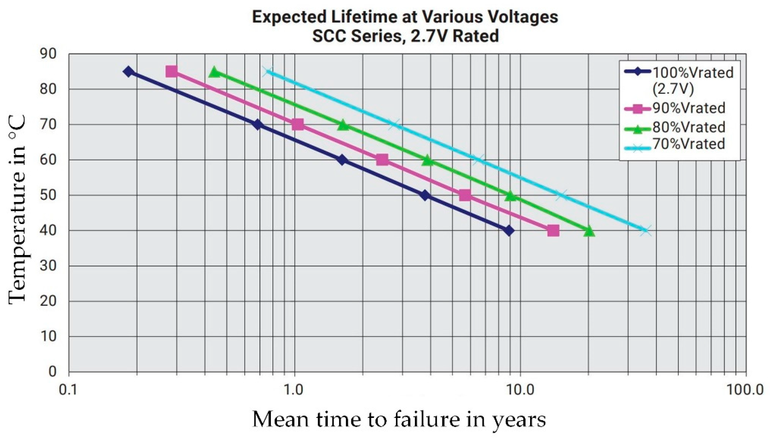
For example, an AVX-SCC series supercap [
8] has a base lifetime expectancy of 20 years at 30 °C in a fully charged state. The temperature coefficient is 8 °C per factor two in a lifetime, and the voltage dependence is 0.4 V per factor two in a lifetime (a lower voltage increases the lifetime, but reduces available capacity)—see
Figure 3.
Similar to the supercap, calendar life of batteries depends on temperature and end-of-charge (EOC) voltage. Unfortunately, in many datasheets, only sparse data sets are given. If anything, one usually finds data regarding temperature dependence. Reasonable EOC voltages for different applications are rarely mentioned in datasheets/literature, with one notable exception being [
15]. Depending on the application,
Table 3 states different suggested EOC voltages. Still, it is not mentioned how much the lifetime is improved, due to voltage reduction.
Additionally, cycling the battery reduces its lifetime. There is no simple correlation between charge/discharge cycles and occurred damage. As mentioned before, it not only depends on the cycle count, but among other factors, also state-of-charge (SOC), DOD and charge/discharge rates. Still, a few basic and generally valid statements can be made:
Just like calendar life, cycle life is influenced by cell temperature, but not necessarily with the same temperature coefficient. e.g., in Reference [
9] the calendar life temperature coefficient is 10 °C per half/double lifetime, but for cycle life, the coefficient is 14 °C.
Increasing charge/discharge rates reduce cycle life. High cycle life values, as shown in
Table 1, are typically obtained by utilizing low charge/discharge rates, e.g., 1 C (1 h charge/discharge rate) or even lower. Increasing these rates, as often necessary for high-speed charging or other heavy-duty applications, reduces lifetime. Especially when the cell is optimized for high specific energy content, which is mainly the case for most batteries used in electric vehicles, where weight is of major interest.
DOD influences the achievable energy throughput [
10,
14]. For example, Saft Evolion (NCA chemistry) reaches a cycle life of 4000 cycles for a DOD of 100% [
14]. For a DOD of 10%, the cycle life increases to 250,000, resulting in a total energy throughput equivalent to 25,000 100%-cycles.
One last comment: In the case of rectangular or pouch bag cells, special care has to be taken for correct mounting that homogeneously compresses the cell with a defined pressure. This is equally important for the proper functioning of the cell, as well as to achieve long cell life.
2.2. Flywheel Energy Storage Systems (FESS)
2.2.1. Background Information
Prices of Lithium-Ion batteries are decreasing on the global market and energy densities have reached reasonable values, allowing EVs to travel 200 km and more on one charge [
18]. However, there are still significant technical challenges, which need to be solved, or alternatives need to be found. One of the major drawbacks of chemical batteries is limited cycle life, which was described in
Section 2.1 and will be discussed in particular in this paper.
It must be stressed that sustainable transportation does not only rely on batteries inside the vehicles. The increasing primary electricity supply through volatile sources, in combination with high grid loads caused by charging power demand, requires decentralized electric energy storage [
19]. The requirements for these stationary energy storage systems may differ significantly from those of transportation applications. However, in both cases, long cycle life and negligible aging effects are usually desired. This is particularly the case when alternatives to chemical batteries come into play.
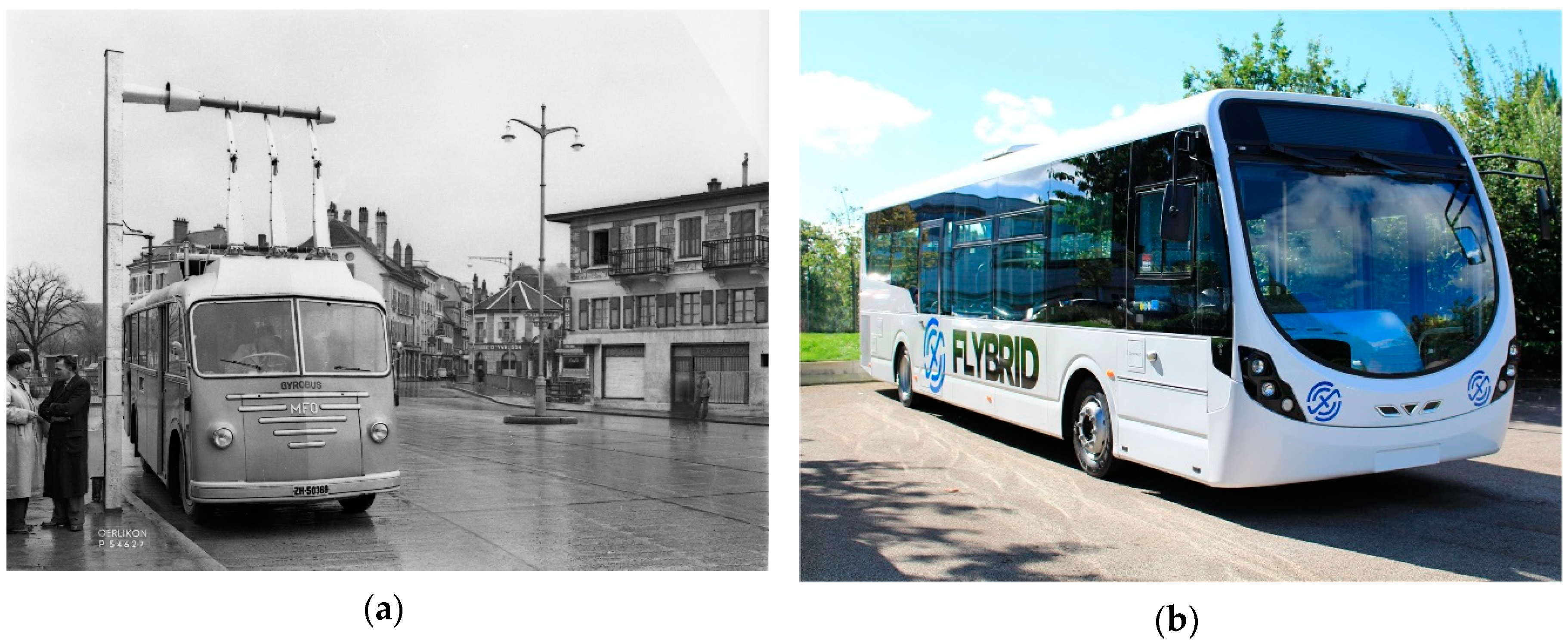
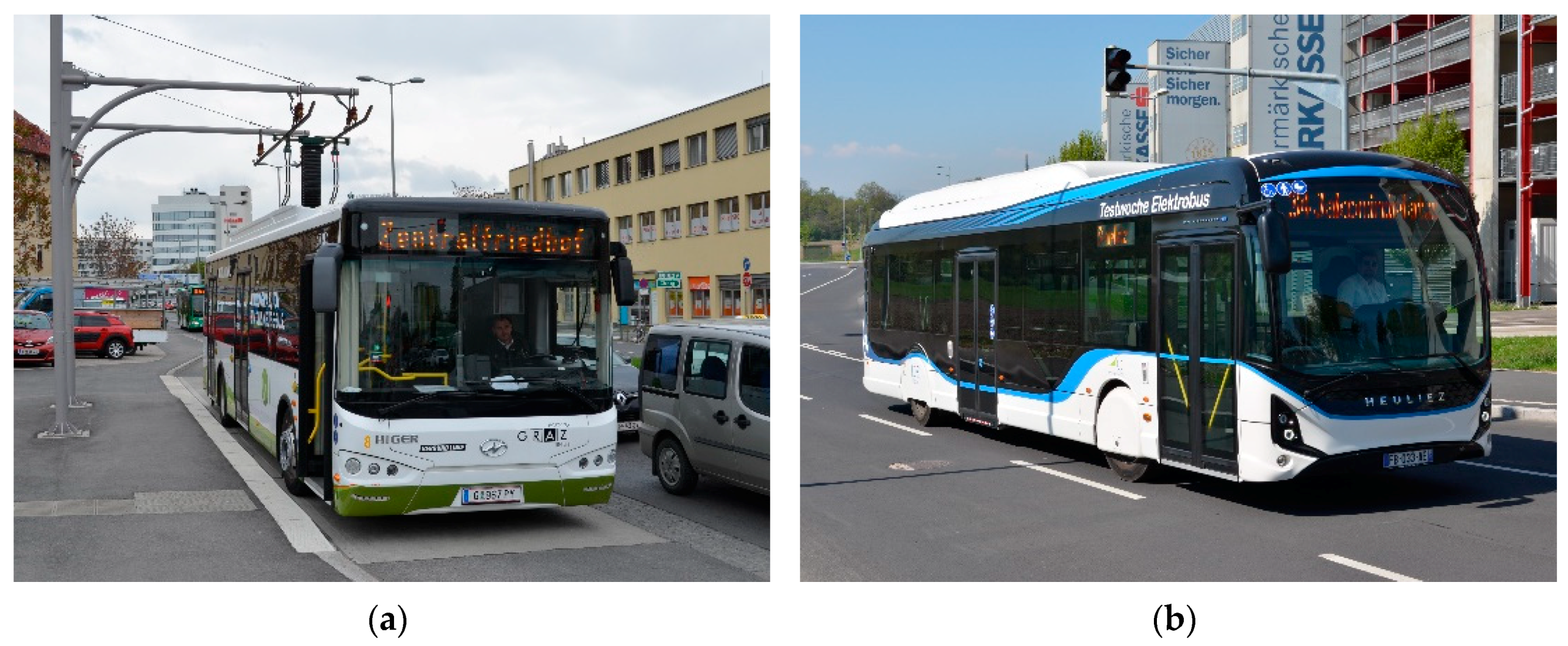
One may think immediately of gyroscopic reactions as a major disadvantage of FESS. This aspect must be considered during system design, but is an issue that can be resolved [
20] as they have been used successfully in various transportation applications (see
Figure 4).
Flywheel Energy Storage Systems (FESS) has experienced a renaissance in recent years, mainly due to some of their intriguing properties:
In principle, an unlimited number of charge/discharge cycles;
No capacity fade over time;
Power and energy content are independent of each other;
Operation at low or elevated temperature is easily possible;
Precise state of charge (SOC)/state of health (SOH) determination;
No risk during transportation/uncritical deep-discharge (flywheel stands still);
No toxicologically critical/limited resources necessarily required.
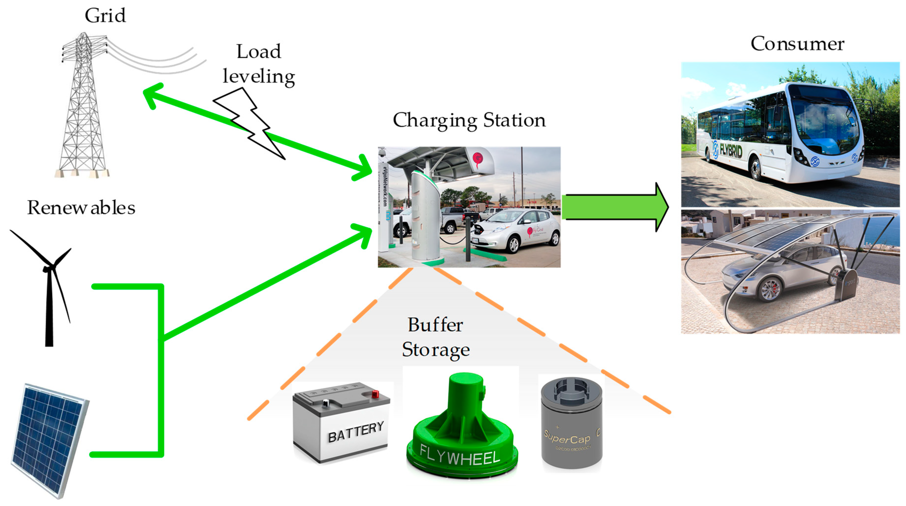
Due to the above-listed properties, FESS are increasingly used for grid stability or fast-charging applications, as proposed in References [
21,
22]. Another example is the currently ongoing Austrian research project “FlyGrid”, within which a FESS for a fully automated EV charging station will be developed. One module of this prototype will be used as the reference case and will deliver 5 kWh at 100 kW peak power.
2.2.2. FESS Working Principle
In a FESS, energy is stored in kinetic form; the working principle is based on the law of conservation of angular momentum. In electromechanical FESSs an external torque is applied to a rotor by the use of a motor/generator, hence, only an electrical and no direct mechanical connection for power transmission is required. In order to charge the FESS, the applied torque accelerates the spinning mass (rotor). If the spinning mass decelerates, energy is taken out of the system, and the motor acts as a generator. Electrical energy from the grid or other sources can be converted into kinetic energy charging the FESS. In the case of discharge, the motor/generator decelerates the spinning mass converting kinetic energy back to electrical energy. This principle is demonstrated in a video in the
Supplementary Materials, that belongs to this publication. The amount of stored energy is defined by the rotor’s moment of inertia and the rotational speed, according to Equation (1).
Kinetic Energy in J
Mass Moment of Inertia of the Spinning Mass/Rotor in kg*m2
Angular Velocity in rad/s
Different concepts for Flywheel Energy Storage Systems (FESS) exist, but within this publication, only electromechanical FESS are considered, as they are easily comparable to any other energy storage system with electric connection terminals.
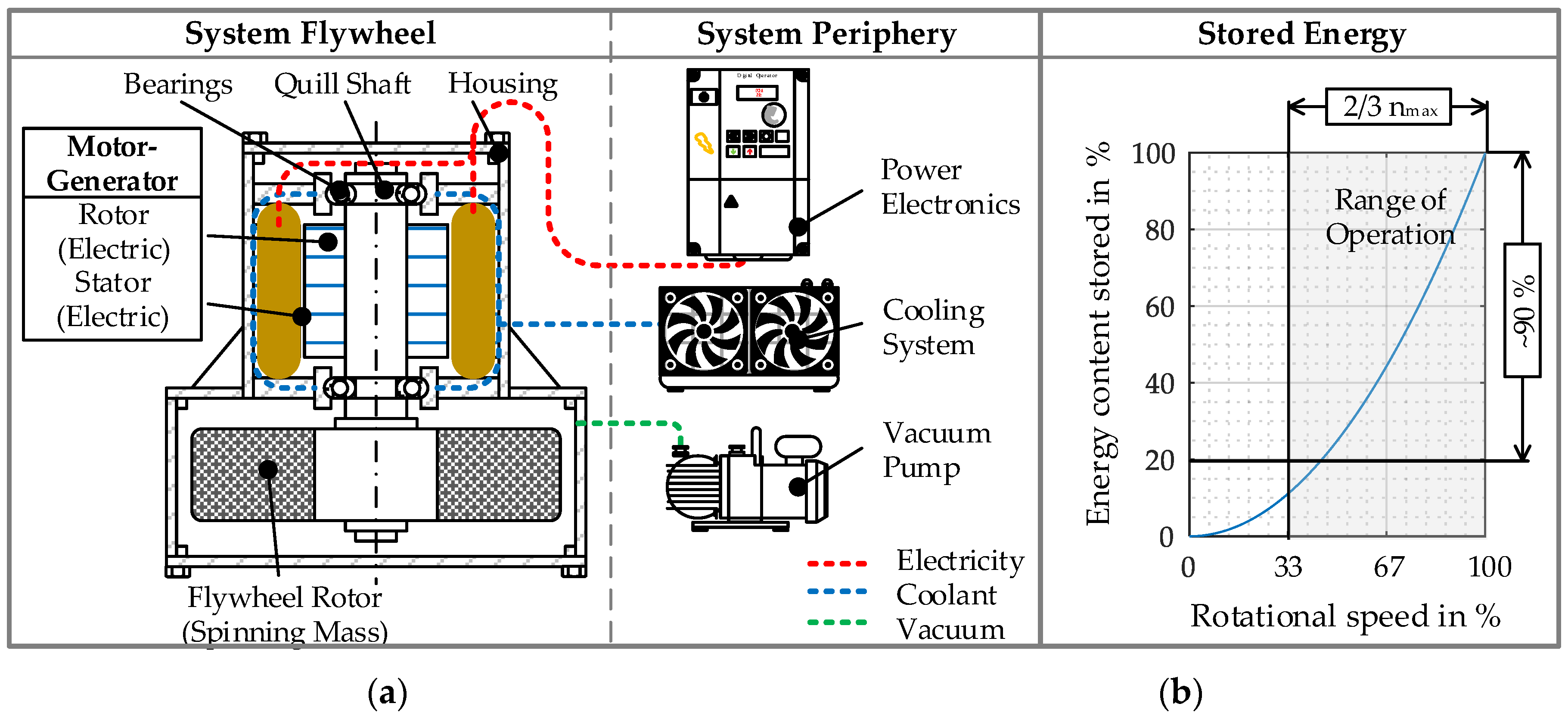
Figure 5a shows a schematic diagram of an electromechanical FESS. It consists of a motor/generator with a shaft and an attached spinning mass. The shaft is supported by bearings, which form the connection to the housing. In
Figure 5b, the energy content is plotted over rotational speed visualizing the quadratic increase of stored energy. If high specific energies are desired, FESS must operate at extremely high rotational speeds, optimally exploiting rotor material strength. Within this publication, only FESS with high specific energies is addressed. As mentioned in
Section 2.2.1 depth of discharge (DoD) does not influence FESS cycle life.
One effect, which must be considered during FESS design is based on Equation (2)—System power is proportional to motor torque and rotational speed. It can be observed that, when the constant power output is required at low rotational speeds, motor-generator torque will reach unnecessarily high values, resulting in heavier and more expensive electric machines. This is why the minimum operating speed is usually kept at around 1/3 of the maximum rpm value.
Power in W
Motor Torque in N*m
Angular Velocity in rad/s
Around 89% of the total kinetic energy of the FESS is usable when the system is operated between 33 and 100% of the maximum permissible speed. For that reason, FESS usually operate within a certain bandwidth and do not decelerate down to standstill during regular operation.
2.2.3. Self-Discharge of FESS
Losses have an important influence on the suitability of this technology for different use-cases. The following paragraph gives a short introduction to this topic, starting with the three main causes of FESS self-discharge:
Air drag losses during operation are crucial for FESS with high specific energies. Circumferential speeds beyond the speed of sound are common and exceed 1 km/s in some cases, which would cause enormous air drag during operation. This air drag would result in losses and eventually be dissipated into heat, which causes thermal issues leading to system failure. In order to reduce these losses, FESS are usually operated in a vacuum atmosphere, and pressure levels down to 1 µbar are common [
23]. At such low-pressure levels, air drag losses play only a minor role. Issues regarding lubrication arising from these vacuum qualities will be addressed in
Section 2.2.6. The power consumption of the vacuum pump and other peripheral components must be taken into account when analyzing the overall system losses. The power dissipated in the bearings also plays a crucial role and will be discussed in detail in
Section 2.2.5.
Losses do not necessarily represent a problem, when they are below a certain level, but the benchmark for this threshold depends on the actual use-case. With increasing mean power-transfer into and out of the FESS, the acceptable level of system losses increases as well.
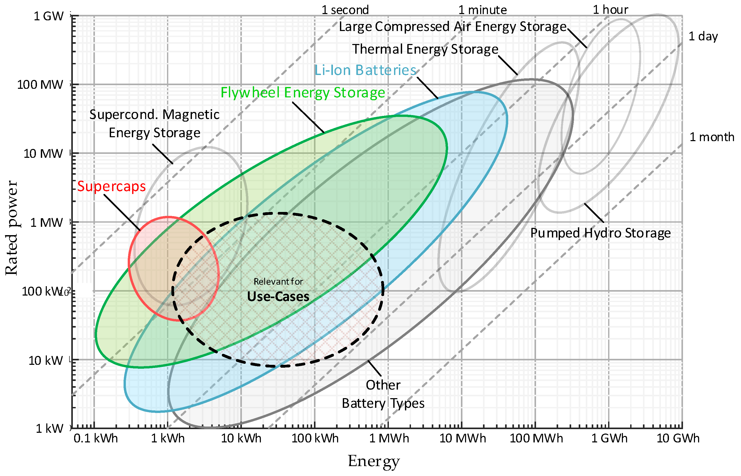
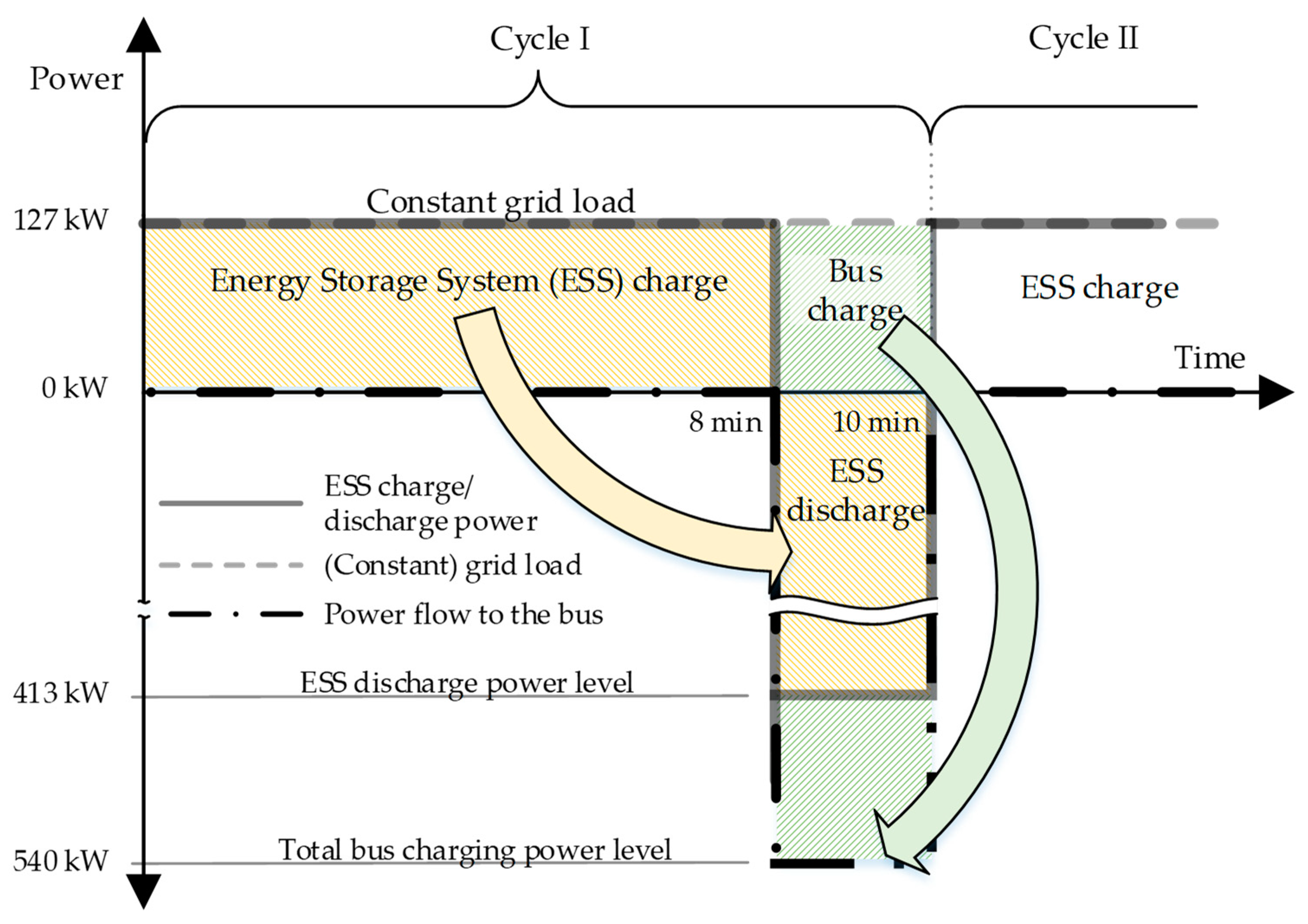
This means that for long term storage (low mean power-transfer), the power loss threshold is very low and FESS is not suitable, due to its relatively high self-discharge (hours to days at most). For highly dynamic and predictable load cycles with high mean power-transfer FESS is more suitable. This matter will be demonstrated in
Section 3 by means of different use-cases.
In the following sections, crucial FESS components will be dealt with, and details regarding their service life will be discussed.
2.2.4. Rotor Material Selection and Aging
As described in
Section 2.2.1 FESS with high energy densities are addressed. Regarding the rotor, rotational speed, and therefore, energy content is limited by permissible stresses (
in the rotor. Highest energy densities can be reached when using materials with high
ratios, like fiber composite materials [
1]. However, other materials like steel are being used in practice as well.
Table 4 compares the theoretical specific energies of different rotor materials.
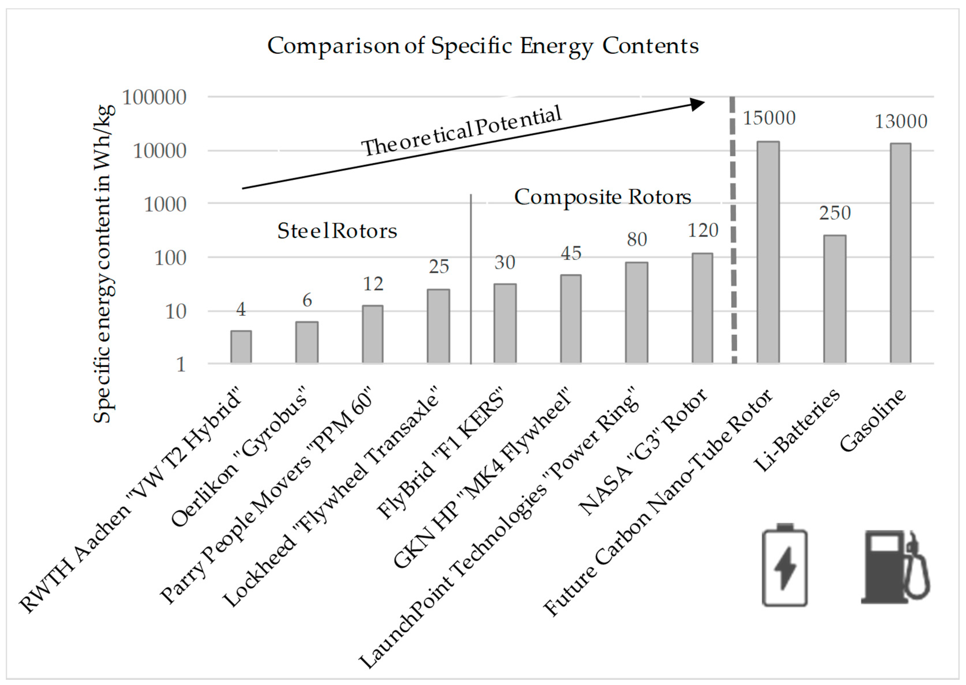
A spinning mass with a kinetic energy content of 5 kWh would weigh around 9 kg when made of carbon fiber reinforced plastic (CFRP) and 137 kg when 42CrMo4 high-strength steel is used, and the material is fully exploited regarding permissible stress. Commercially available systems reach specific energies regarding the rotor up to 50 Wh/kg when using CFRP, for steel flywheels, according to values are much lower.
However, it must be mentioned that the theoretical specific energy values are reduced by design parameters, such as safety factors, stress concentration (notching), etc.
Figure 6 depicts the specific energy content of various real flywheel rotors with Li-batteries and fossil fuels. To show the enormous future potential of FESS technology, the theoretical specific energy potential of a rotor made from a material with properties similar to carbo nano-tubes is shown as well.
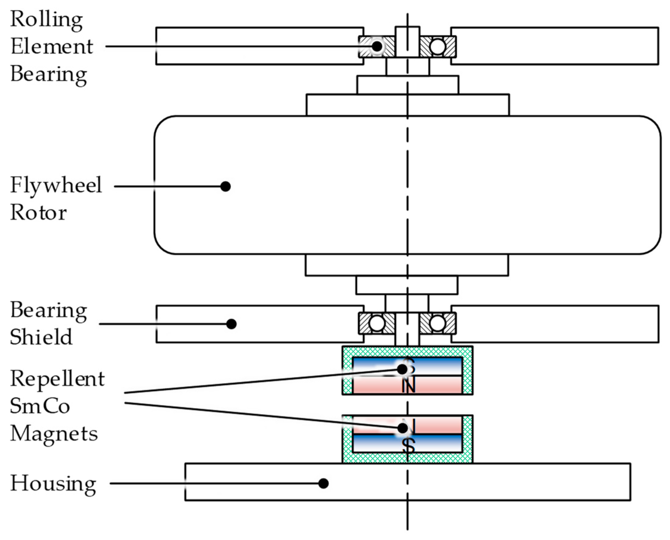
Usually, the rotor weight is being compensated using a magnet (permanent magnetic thrust bearing), so that the ball bearings are not subjected to the entire rotor weight. The influence of rotor weight compensation is discussed in detail in
Section 2.2.5.
While in theory FESS rotors are also subject to aging, due to fatigue stress (or even creep in the case of CFRP rotors) it must be mentioned that these phenomena are usually considered during the design phase by the introduction of a safety factor, and hence, do not result in the capacity fade of the system. In this regard, even rotors made of CFRP can reach high service life when they are designed accordingly, and aging of the matrix is considered [
25].
2.2.5. Bearings
In most FESS, two fundamentally different bearing concepts are used: Active magnetic bearings (AMBs) and rolling element bearings (REBs). High costs compared to competing energy storage devices represent one of the major market entry barriers for FESS. For that reason, the upcoming sections focuses on low-cost solutions using REBs.
Table 5 gives a brief overview of REBs compared to AMBs.
The REB’s service life mainly depends on the applied loads. Generally, bearing loads are caused by rotor weight and machine dynamics/imbalance forces. There are different approaches to minimize bearing loads:
Resilient bearing seat/supercritical rotor operation [
26,
27];
Passive magnetic weight compensation [
20,
28];
Precise rotor balancing [
20,
29];
Active vibration control concepts [
30].
Concepts based on active vibration control will not be considered within this publication as they have not reached readiness for marketing in FESS yet [
26]. The other three measures are considered and explained briefly in the following paragraph using an example with the specific properties stated in
Table 6:
Axial bearing loads can, in fact, be almost entirely compensated by a passive magnetic lifting system, as shown in
Figure 7, provided the system is designed with a vertical axis of rotation, which is normally the case. As shown in
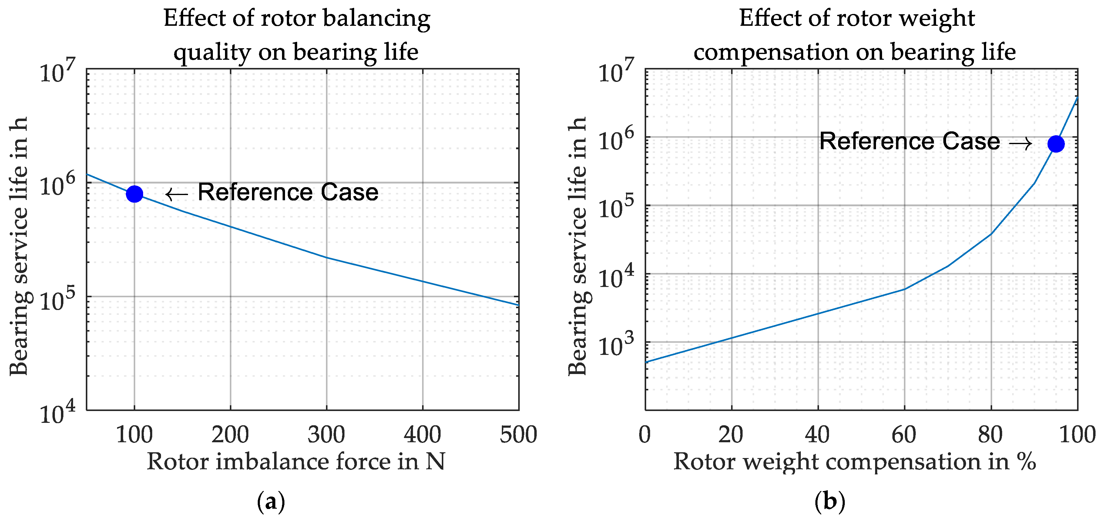
Figure 8a weight compensation is key to reach reasonable bearing service life. An attracting configuration using a ring magnet that would directly pull a ferromagnetic steel element on rotor upward has some disadvantages because of high eddy current losses at high rotor speeds. Using an additional permanent magnet on the rotor acting as a counter pole, the eddy current losses can be almost eliminated. For the remaining decision of either pulling the rotor on top or pushing it upwards from magnets mounted at the bottom, the latter configuration is preferable, due to its inherent stability of this configuration taking into account the direction of gravity. A demonstration video showing this configuration is uploaded in the
Supplementary Materials of this publication.
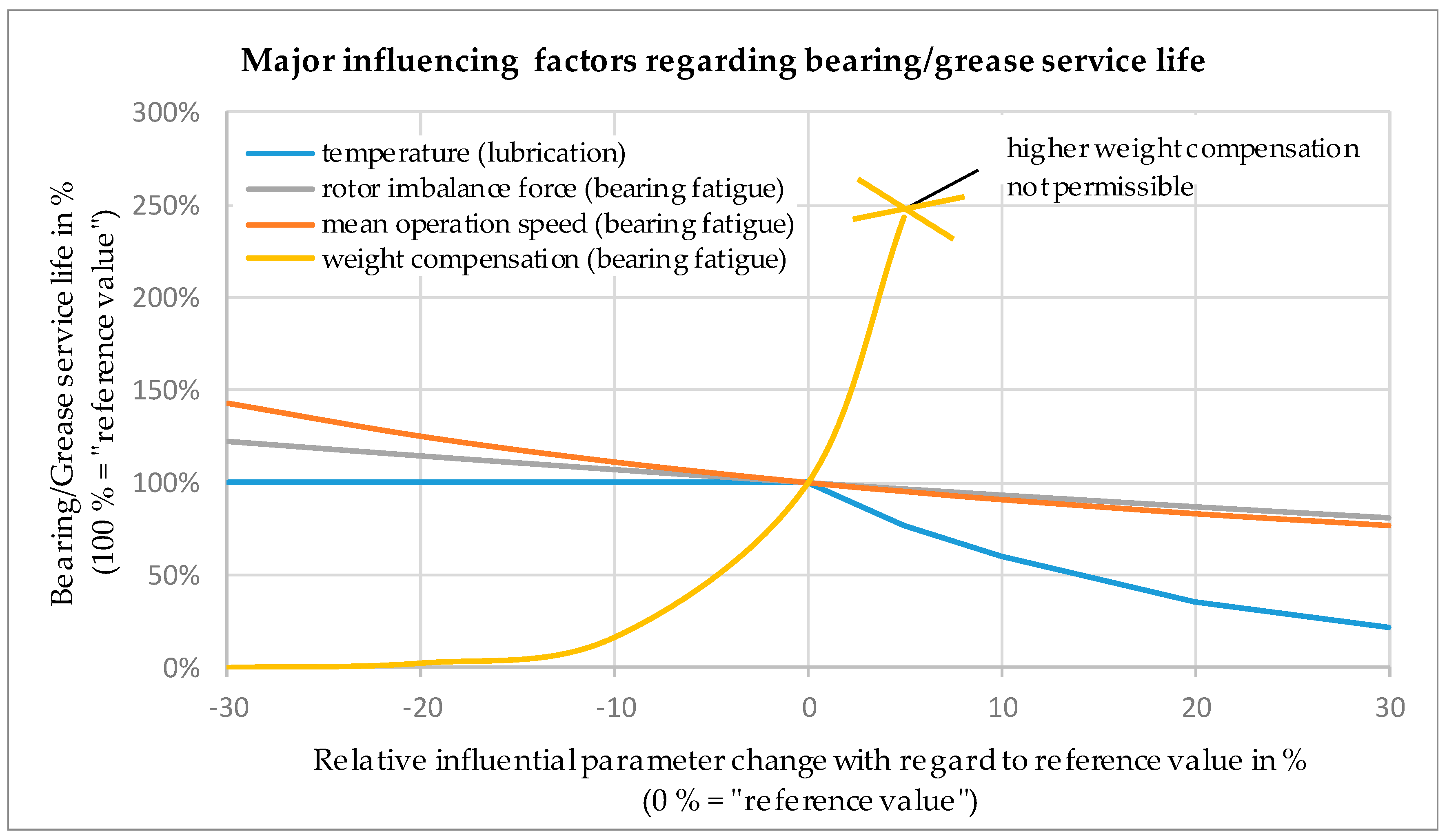
However, even if the rotor weight is nearly entirely compensated, imbalance forces remain. Based on a constant imbalance force of 100 N, bearing life for different compensation levels is shown. Without weight compensation, the bearings last only 21 days, but when 95% of the weight is compensated, bearing life increases up to more than 90 years. It must be noted that at compensation levels above 100% one bearing might be completely relieved which may cause slippage of the balls and lead to rapid system failure [
31].
A flexible bearing suspension is used to operate the rotor supercritically. This means that at least the first two eigenfrequencies are surpassed and “self-centering” of the rotor occurs. During supercritical rotor operation bearing primarily loads, depend on the bearing seat’s stiffness and the rotor imbalance and not on rotational speed [
26].
Figure 8b shows the decrease of bearing life from 90 years to 25 years, when the rotor imbalance force is increased from 100 N to 300 N. Higher imbalance requires higher axial prestress of the bearing configuration, which is taken into account. For this study a magnetic weight compensation of 95% resulting in a remaining weight load of 74 N is assumed. Still, it must be mentioned that rotor imbalance may change over time, due to creep, wear or setting of joints.
Bearing friction torque is one of the main causes of losses in FESS and is mainly influenced by the following parameters:
● Size and geometry of the bearing
● Applied loads | ● Rotational speed
● Lubrication |
In order to calculate the resulting power loss bearing friction torque must be multiplied with the rotational speed.
The influence of bearing size, cage material and weight compensation factor on torque loss is a very complex matter and outside the scope of this publication. Detailed studies on the minimization of FESS bearing losses are available in References [
1,
32,
33]. Still, as lubrication strongly affects FESS service life, the effects of lubricant viscosity and minimum quantity lubrication are discussed in the subsequent
Section 2.2.7.
2.2.6. Lubrication
Generally speaking, there are three different lubrication principles for high speed rolling element bearings in FESS:
| ● Grease | ● Oil | ● Solid lubrication |
For the considered use-cases are only oil and grease lubrication are relevant, as solid lubrication is mainly used when ambient pressures below 0.1 to 0.01 μbar are required [
34]. Furthermore, oil and grease have superior service life for application in FESS compared to solid lubrication, and both are applicable for the considered use-cases. It must be noted that special vacuum grease/oil must be used in order to avoid outgassing, which has a detrimental effect on vacuum quality and may even lead to system failure.
Grease lubrication represents the most commonly used lubricating concept because it requires the least constructive and financial effort to implement, but shows some drawbacks regarding service life compared to oil lubrication [
35]. Usually, fresh grease is stored in cartridges and extracted on demand. Standard recommended shelf life for grease in closed and sealed cartridges goes up to five years when stored properly [
36]. During operation, service life depends strongly on applied loads and temperature. Above the permissible continuous maximum temperature for a specific grease, a temperature rise of 15 °C cuts grease service life in half [
32]. Therefore, thermal management is crucial for FESS. In order to reach high service life, ongoing maintenance and grease change is required.
Oil lubrication is superior to grease with respect to service life. The used oil can be filtered continuously, thermally conditioned and may easily be changed on demand. Initial costs and effort to implement an oil lubrication circuit are significantly higher compared to grease. Due to the operation under vacuum, the lubrication concept must meet special requirements. Though the functionality of oil lubrication in FESS has been demonstrated in various research projects [
37], these systems are not available off-the-shelf.
2.2.7. FESS Service Life
Based on the reference system presented in
Table 6,
Figure 9 summarizes the main influencing factors and their effect on bearing and lubrication service life.
In this example, grease lubrication and operation at the maximum continuous temperature limit are assumed. Therefore, every increase of 15 °C decreases lubrication service life by 50% until the maximum permissible operating temperature is reached (not shown in
Figure 9). In short, FESS service life > 25 years is feasible with only minor maintenance effort.
