1. Introduction
Concrete has been applied to various types of structures worldwide, including reinforced concrete structures, dams, tunnel lining, concrete retaining walls, and pavement. However, the destruction and cracking of concrete owing to various influences of these structures as time passes has caused serious damage to human life and property. Therefore, safety inspections and evaluations of concrete structures are particularly important.
Concrete face rockfill dams (CFRDs) are relatively easy to construct and economical to manage, and have less impact from weather and earthquakes than other types of dams [
1]. The concrete face slab considered herein is a concrete plate-type structure located on the upstream face of a rockfill dam body, and is used as an anti-seepage structure. Therefore, damage occurring in the cavity behind the concrete face slab may cause a deformation and collapse of the dam body. If a cavity occurs beneath the concrete slab, cracks may occur from hydraulic pressure or a dead load, which may cause problems such as a load being applied to the lower part of the plinth owing to a decrease in frictional force between the concrete face slab and the zone materials of the dam body.
Non-destructive testing (NDT) methods such as ground penetrating radar (GPR), electric, seismic, and radioactive surveys are widely used safety inspection methods of concrete face slabs. There are also computer image analysis techniques for assessing the condition of concrete structures, such as assessing the degree of cracking of the structure [
2,
3,
4]. Other studies have analyzed CFRD stability problems through a numerical analysis or model experiment. Seo et al. conducted centrifuge model tests for simulating the behavior of CFRD with increasing water levels [
5]. Cheng and Zhang conducted a study on the dynamic response and deformation law by changing the waveform of the input wave using a centrifuge model test [
6]. Arici analyzed the state of the stress and the cracking behavior of a concrete face slab over both the short and long term during the lifecycle of a CFRD [
7]. Zhang et al. detected cavities that may exist beneath a concrete face slab of a seawall using GPR [
8].
The stability problems caused by a concrete face slab are as follows: The cracking behavior of a concrete face slab of CFRD under intense seismic excitation is not the opening of the vertical joints but rather the cracking of the concrete plate from crushing between the concrete face slab and the underlying support layer and an excessive settlement of the fill [
9,
10]. The major factors indicating the deformation characteristics after an initial impoundment are the crest and face settlements [
11]. The cracking of the concrete face slab is associated with seepage [
12]. Therefore, a concrete face slab that applies the core function of the CFRD should have mechanical properties preventing cracking from an external force, or tensile stress of the concrete from moment generation [
13]. In other words, the vulnerability of a concrete face slab adversely affects the stability of the CFRD.
In this study, we investigated the conditions of the concrete face slab and detected the cavity between the concrete face slab and underlying support layer for a safety inspection and quality control of the CFRD. As the NDT methods, we applied impulse response (IR) and electrical resistivity tomography (ERT) methods using non-destructive electrodes. IR methods are widely used in the safety inspection of concrete cracks, cavities underneath the concrete, pavement, and other elements, and are applied to investigate the conditions of the concrete based on the dynamic stiffness and average mobility. ERT methods using non-destructive electrodes have been developed to reduce the contact resistance of the concrete and prevent the destruction of the object of investigation, and are used to investigate the conditions of the concrete through a two-dimensional (2D) electrical resistivity section. Therefore, the NDT of a concrete face slab was carried out through an analysis and correlation between the two methods.
2. Study Object
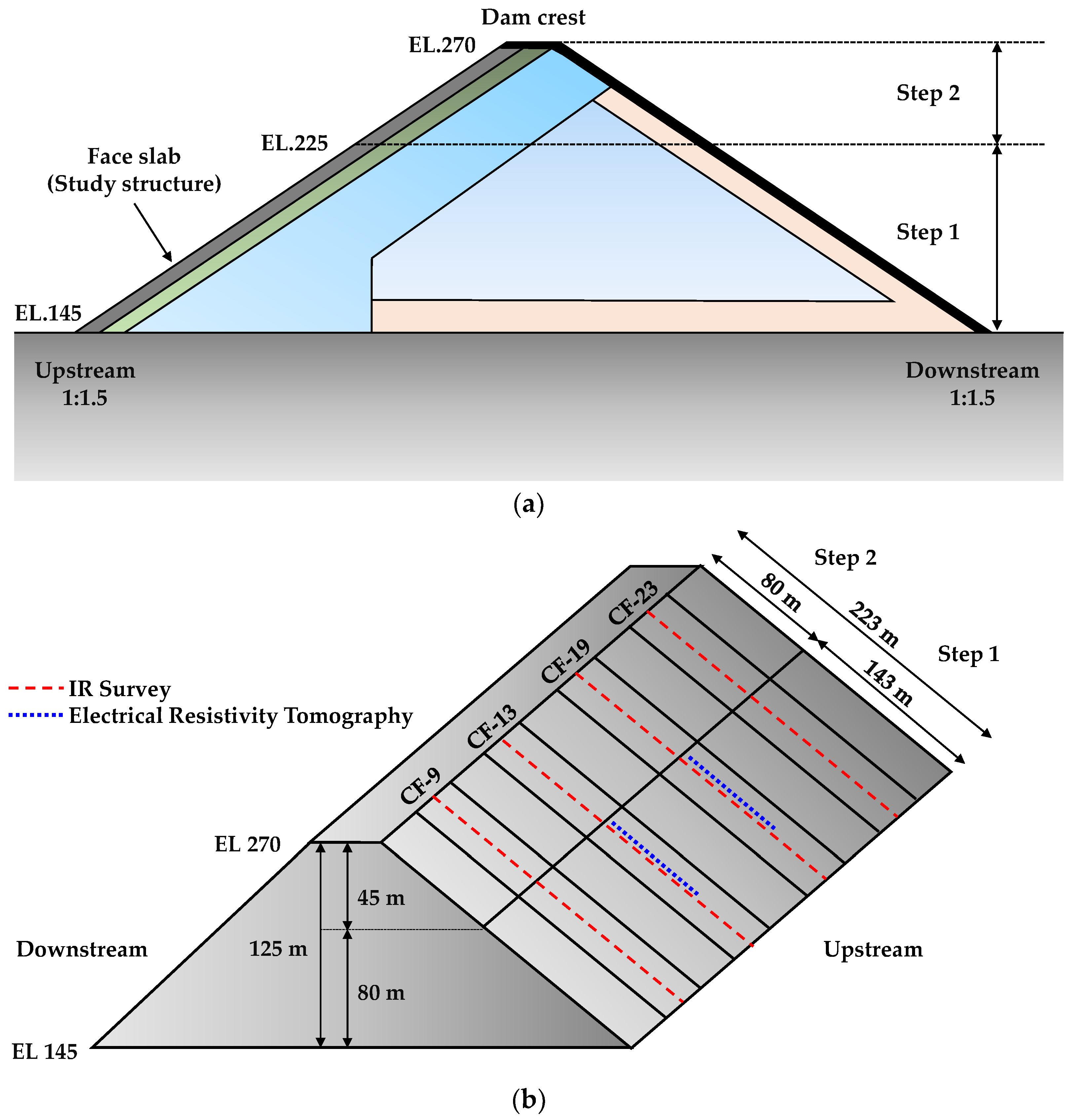
The target object was a CFRD located in the northern district of the Republic of Korea, with a dam height of 125 m, a crest length of 601 m, a maximum reservoir capacity of 2.63 billion m
3, and a ratio of upstream slope to downstream slope of 1:1.5 (
Figure 1a). Step 1 of the dam was completed in 1989, and step 2 in 2006.
In general, the thickness of the concrete face slab was 0.3 m at the top, except for the case of a low dam height, and changes according to the depth of the water (H) while descending to the bottom of the concrete face slab [
14]. Therefore, the thickness of the concrete face slab for step 1 was thicker than that of step 2. In addition, the steel reinforcements were designed using a 0.4–0.5% steel ratio to avoid cracks from the tensile stress that occurs through changes in temperature, and were arranged at intervals of 200–300 mm to cope effectively with cracks.
Figure 1b shows a schematic of the IR and ERT survey lines of the study object, namely, CF-9, -13, -19, and -23 of a concrete face slab, with a width of 15 m upstream, all of which are located at the center. The IR survey was carried out in steps 1 and 2, and the ERT survey was carried out at CF-13 and -19 in step 2. Both surveys were conducted from top to bottom. Through the IR survey, 21 stations were acquired for a length of 79 m in step 2, and 23 stations were acquired for a length of 80 m in step 1. The spacing of the stations was set to 2.5 m for the cavity estimation examined through a GPR survey [
15], and 5 m for the other section. Through the ERT survey, 32 channel cables were used, and the electrode spacing and line length were set to 1 and 31 m, respectively, when taking into account the thickness of the concrete face slab and the steel reinforcement.
3. Application of Non-destructive Testing to Test Bed
An IR survey is a method used to detect the internal defects of a structure by applying a mechanical impact to the concrete surface based on elastic waves. This technique can be widely applied to concrete structures such as bridges, roads, and dams, and can be used to quickly investigate large areas [
16]. In addition, it has the advantage of non-destructively investigating the cracks and cavities of an applied concrete structure.
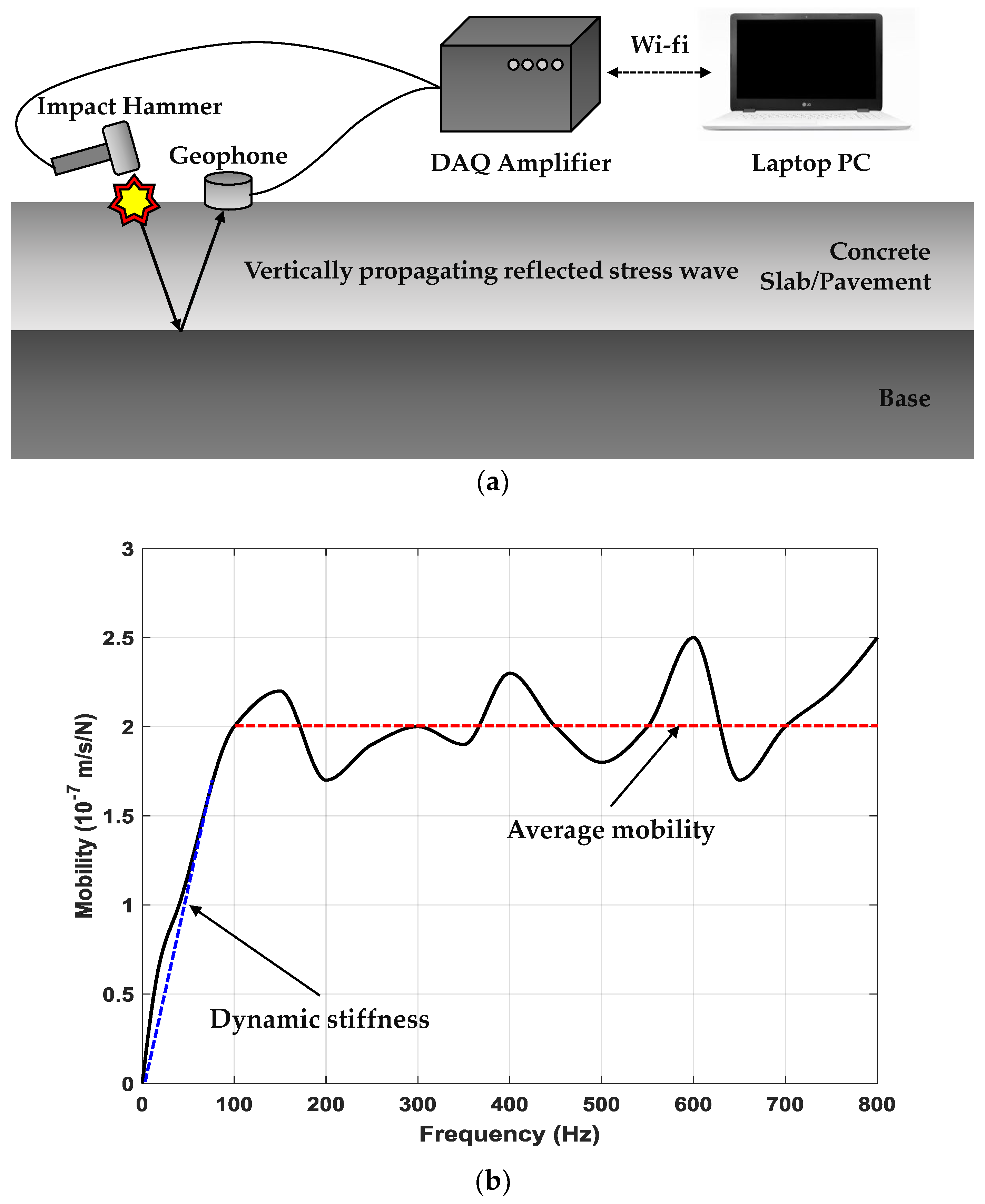
Figure 2 shows a schematic of the impact response tester developed by Chung et al. [
17] and a graph of the mobility-frequency of a plate-like object such as a typical concrete face slab.
Figure 2a shows the data acquisition device (DAQ), impact hammer with a load cell, and geophone applied. During an IR measurement, communication between the DAQ and a laptop PC is achieved through the wireless fidelity (Wi-Fi) ad hoc mode, and data are saved wirelessly. The stored data is transformed into the frequency-domain using a fast Fourier transform algorithm after applying bandpass filtering to the spectrum of the time-domain generated by the impact source and geophone velocity transducer. When an impact is applied to the study object using an impact hammer, the object on the plate reacts in bending mode within a frequency range of 0 to 800 Hz, and the geophone measures the velocity of the bending motion [
18]. The IR method obtains the transfer function from the impact force measured in the load cell attached to the impact hammer and the velocity of the bending motion measured using the geophone. The transfer function is defined as the ratio of the velocity spectrum to the force spectrum, which is called mobility. The mobility at a frequency range of 0–800 Hz also includes the parameter information based on the conditions and integrity of the concrete study object.
Figure 2b shows an example graph of the dynamic stiffness and average mobility in a plate-like object such as a concrete face slab. The dynamic stiffness is defined as the reciprocal of the slope at a frequency of less than 80 Hz where the mobility increases linearly in the mobility-frequency graph. The dynamic stiffness indicates the flexibility around the measurement point and depends on the quality of the study object, the thickness of the plate, and the supporting state of the plate. The average mobility is defined as the arithmetic mean of the mobility within the 100–800 Hz frequency range. The elastic wave caused by the applied impact source is attenuated by the intrinsic rigidity of the plate. The average mobility within the 100–800 Hz range is directly related to the plate density and thickness. The average mobility increases when the thickness of the plate becomes thinner or the distance between two layers of the specimen decreases.
Various electrical resistivity measurement techniques for concrete have been developed, including a uniaxial method and a four-point method [
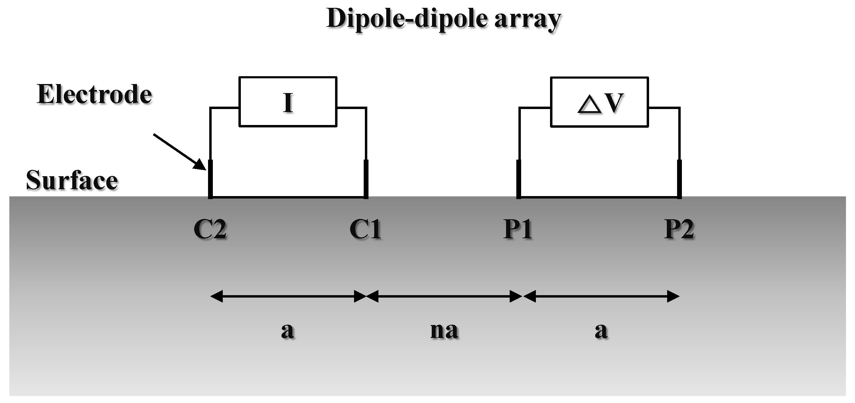
19]. These techniques are mainly for quality control and a durability evaluation of concrete. In this study, however, the ERT method of a dipole-dipole array was used to obtain a 2D section of the electrical resistivity distribution. In general, an ERT survey is applied to underground exploration, and is a geophysical exploration technique for investigating the geological structure and ground condition by measuring the potential difference between electrodes caused by the electric current flowing from the current electrode. In addition, the non-destructive electrode was used because the electrodes of the stainless steel used in the ERT survey could cause destruction of the study object.
Figure 3 shows a schematic diagram of an ERT survey using a dipole-dipole array. The potential difference (
∆V) was measured by flowing a current (
I) during the ERT survey, as characterized through Equations (1) and (2) below:
where
ρa is the apparent resistivity of an underground medium,
k is the geometrical factor,
a is the electrode spacing, and
n is the electrode separation index. However, because the measured
ρa is not the true resistivity, it must be calculated through an analysis technique. For this, DIPRO for Windows [
20] was used.
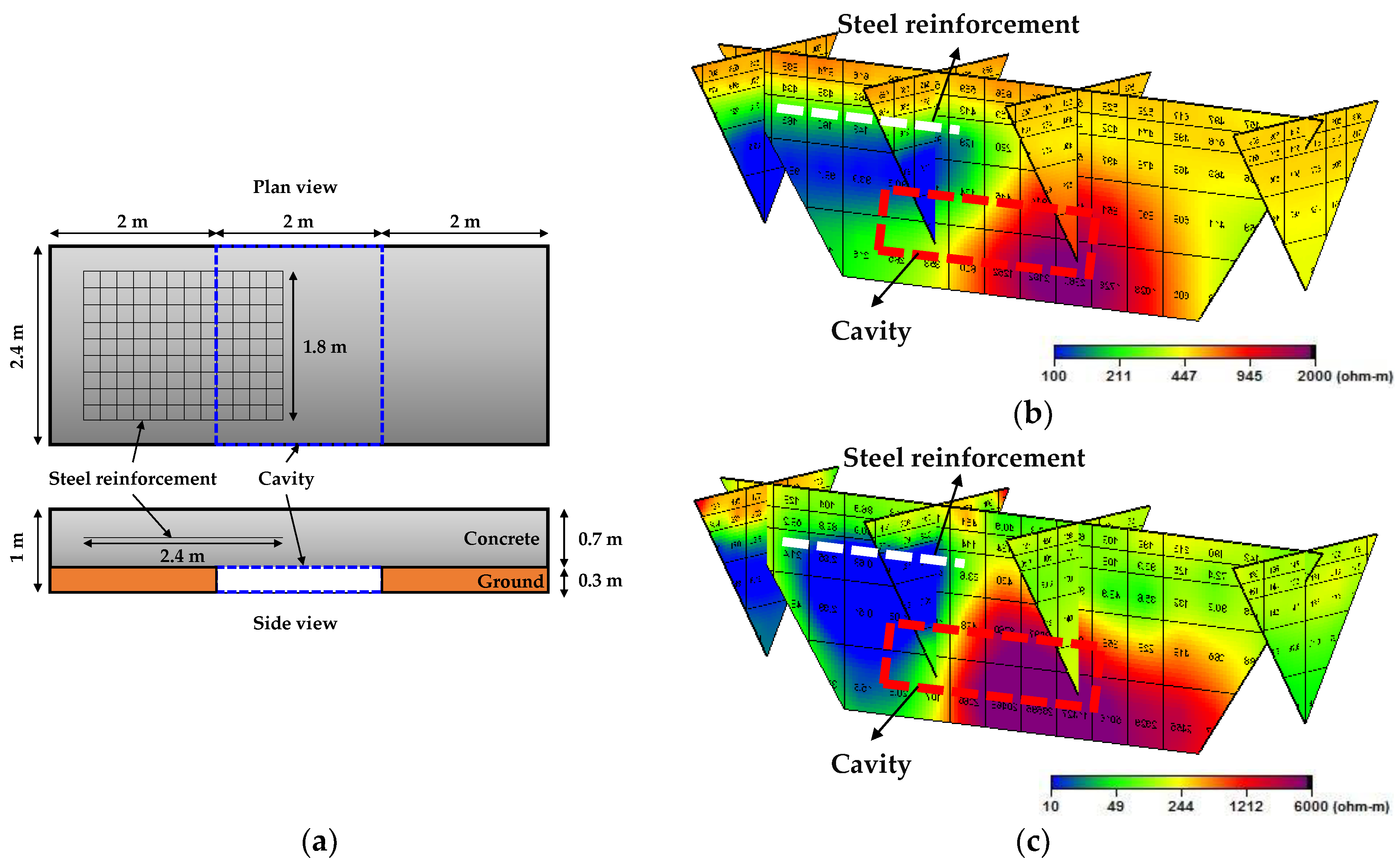
Figure 4 shows the concrete model manufactured for reviewing the applicability of an ERT survey of concrete, as well as the results of inverse and forward modeling. The concrete model was made to confirm the effects of the steel reinforcement and cavities, and was 2.4 × 6.0 × 1.0 m
3 in size (
Figure 4a). Steel reinforcements were arranged at the center of the left side of the concrete at 0.2 m intervals with a 25 mm diameter mesh. The cavity was located at the center of the bottom of the concrete and was 2.4 × 2.0 × 0.3 m
3 in size. Sand, gravel, and clay were used to support the concrete on the left and right sides of the cavity, and at the same time, to reduce the change in the height of the cavity owing to a consolidation of the ground.
Figure 4b,c show the inversion using non-destructive electrodes, and the forward modeling results, respectively. In both results, the effect of the electrical resistivity was shown through the low resistivity effect at the location of the steel reinforcement and the high resistivity effect at the location of the cavity. Both effects also fitted well with the actual location. As a result of both models, an absolute difference in the resistivity value existed, although this occurred because the resistivity value of the actual concrete was different from the resistivity value used for the forward modeling. However, an ERT survey could be applied to the concrete face slab because the effects of the steel reinforcement and cavity of the concrete were quite visible.
4. Results and Discussion
4.1. Impulse Response Results
The IR survey was applied to steps 1 and 2 of the upstream slope of the concrete face slab. The dynamic stiffness and average mobility could not be evaluated absolutely because each step had a different construction time and concrete thickness. Owing to the characteristics of the IR method, the parameters showed a difference in the average mobility as the thickness of the plate decreased. In addition, the dynamic stiffness decreased as the thickness of the reflected layer decreased. Therefore, the results of the IR survey were interpreted independently for each step.
Figure 5 shows dynamic stiffness and average mobility graphs for each step.
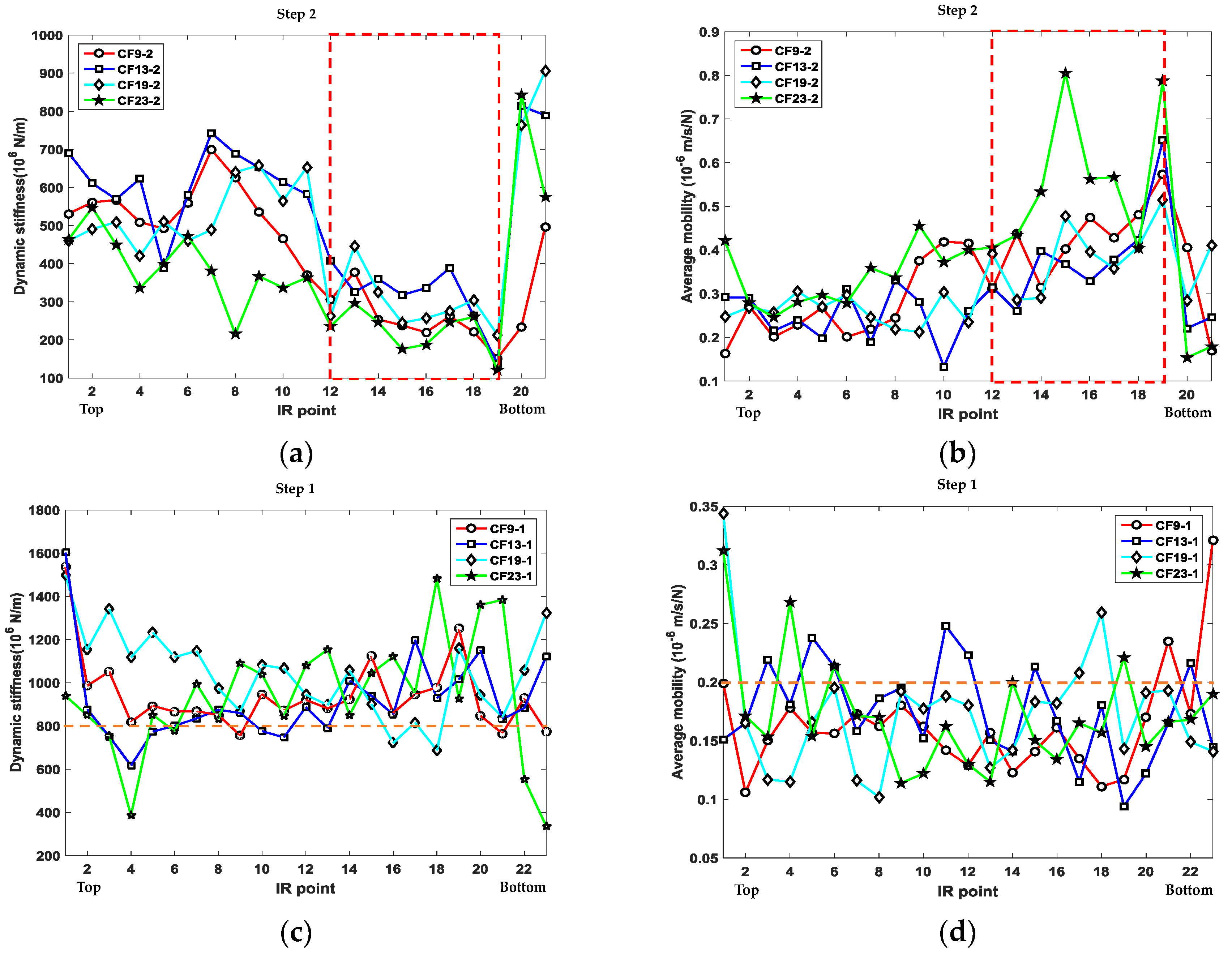
Figure 5a,b show the dynamic stiffness and average mobility at CF-9, -13, -19, and -23 of the concrete face slab. This plot shows an inverse relationship between the general dynamic stiffness and average mobility. The overall dynamic stiffness decreased from top to bottom (IR points 1–19), and then tended to increase sharply at the bottom (IR points 20 and 21). In particular, at IR points 12–19, the entire concrete face slab showed a relatively low dynamic stiffness and high average mobility (red dotted box). In addition, throughout the concrete face slab shown in this box, CF-23 was expected to be the most vulnerable. The overall upstream slope of step 2 indicated that the state between the concrete face slab and the underlying support layer was more unstable at the bottom than at the top, and that a cavity was likely to exist at the bottom. IR points 20 and 21 exhibited a sharp high dynamic stiffness and low average mobility, which was presumed to maintain the high quality of the concrete because the supporting soil in the red dotted box was lost, accumulated at the bottom, or no space existed where the supporting soil would be lost near the bottom.
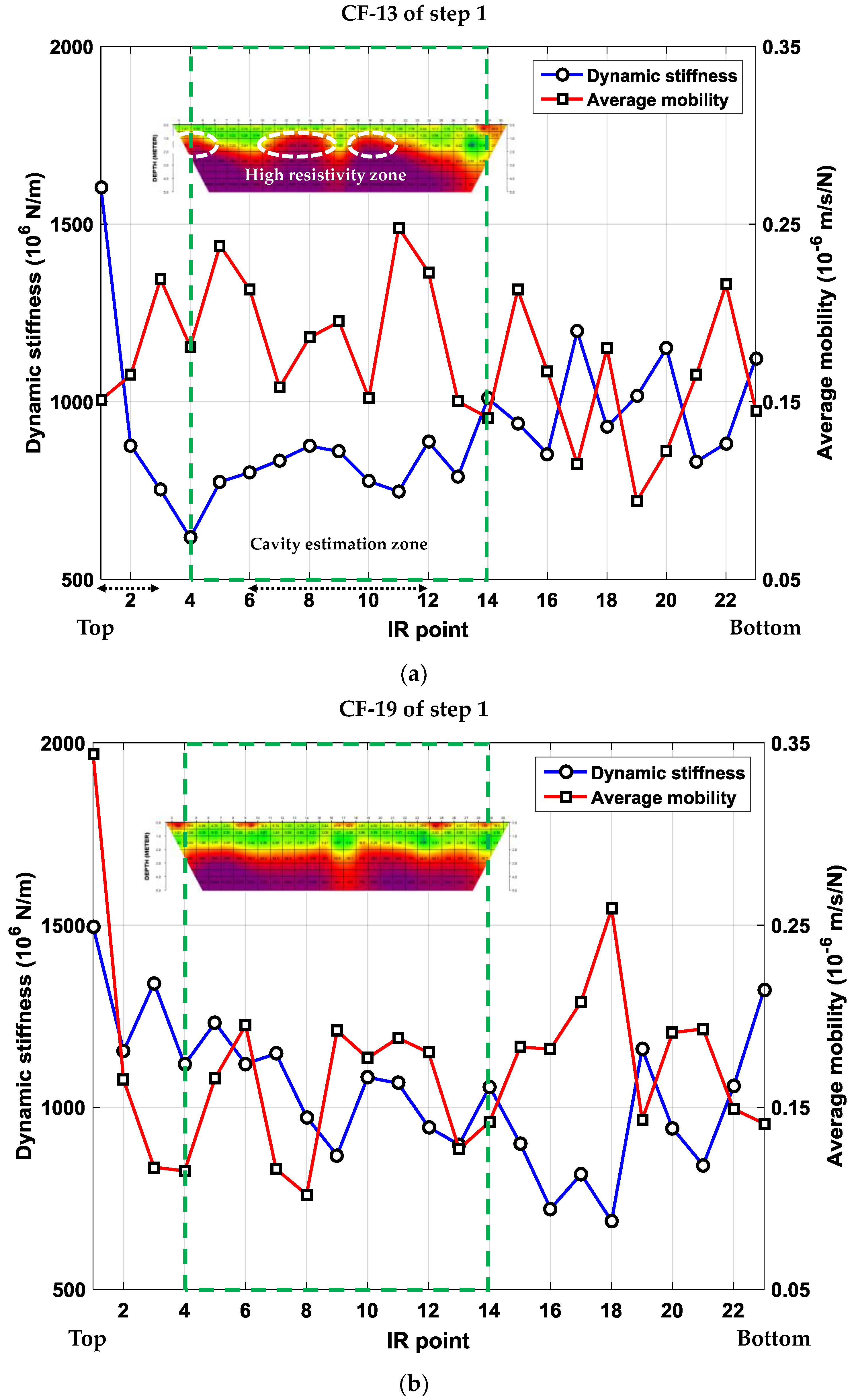
Figure 5c,d showed the dynamic stiffness and average mobility at CF-9, -13, -19, and 23 of the concrete face slab. In steps 1 and 2, the concrete face slab showed a tendency to remain relatively constant in terms of the dynamic stiffness and average mobility, the former of which tended to remain at above 800 × 10
6 N/m. The average mobility tended to remain constant, usually at below 0.2 × 10
−6 m/s/N, however, the average mobility of some of the IR points was relatively large. IR points 4, 22, and 23 showed a low dynamic stiffness and a poor concrete quality compared to the other points on the concrete face slab. In particular, IR point 4 of CF-23 tended to have a low dynamic stiffness and high average mobility. These points were relatively weak at supporting the concrete face slab and predicting potential cavities.
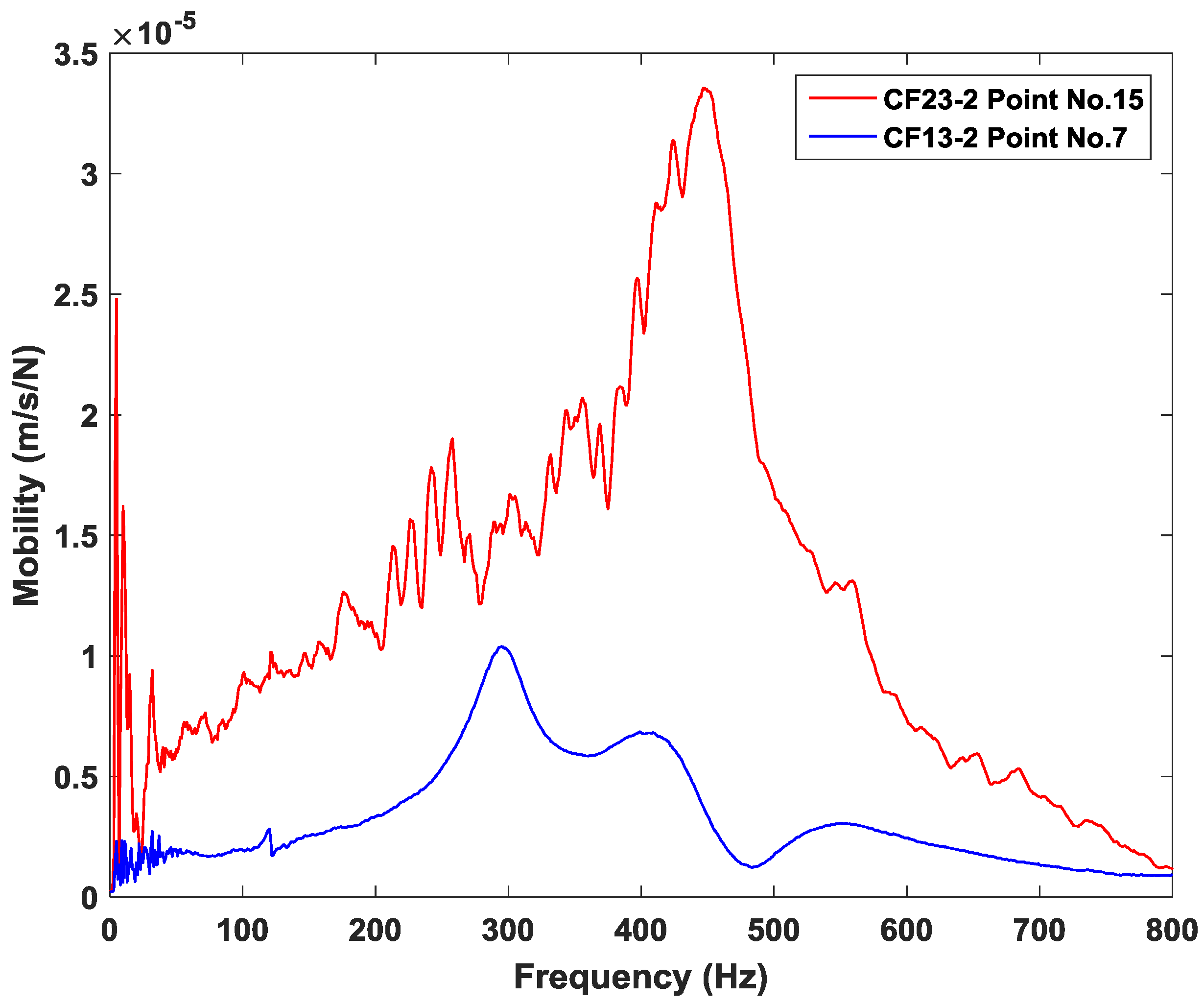
Figure 6 shows a mobility-frequency graph for the concrete face slab in step 2 according to the concrete conditions. IR point 15 of CF-23 was very low in dynamic stiffness and the highest in mobility. In contrast, IR point 7 of CF-13 was very low in average mobility and very high in dynamic stiffness. In general, the increase in mobility at below 80 Hz indicated that a cavity was likely to exist below the concrete face slab, and if a crack was present in the concrete, the mobility slope tended to increase [
21]. IR point 15 of CF-23, which showed this tendency, demonstrated a relatively poor concrete quality, whereas IR point 7 of CF-13 was relatively stable before and after 80 Hz, indicating a high concrete quality. Therefore, the concrete condition can be distinguished according to the mobility-frequency characteristics of the raw data, and an IR survey is considered to be suitable for evaluating the condition of a concrete face slab.
4.2. Electrical Resistivity Tomography Results
An ERT survey using non-destructive electrodes was applied to the concrete face slab at CF-13 and -19 in step 1. The cavity-estimated zone of CF-13 surveyed using GPR was located at 10 to 30 m from the dam berm, and no cavity was found at CF-19 [
12]. Therefore, when an ERT is applied, the existence of a cavity can be identified based on an electrical resistivity distribution, and it can be confirmed whether an anomaly exists in the actual cavity estimation zone.
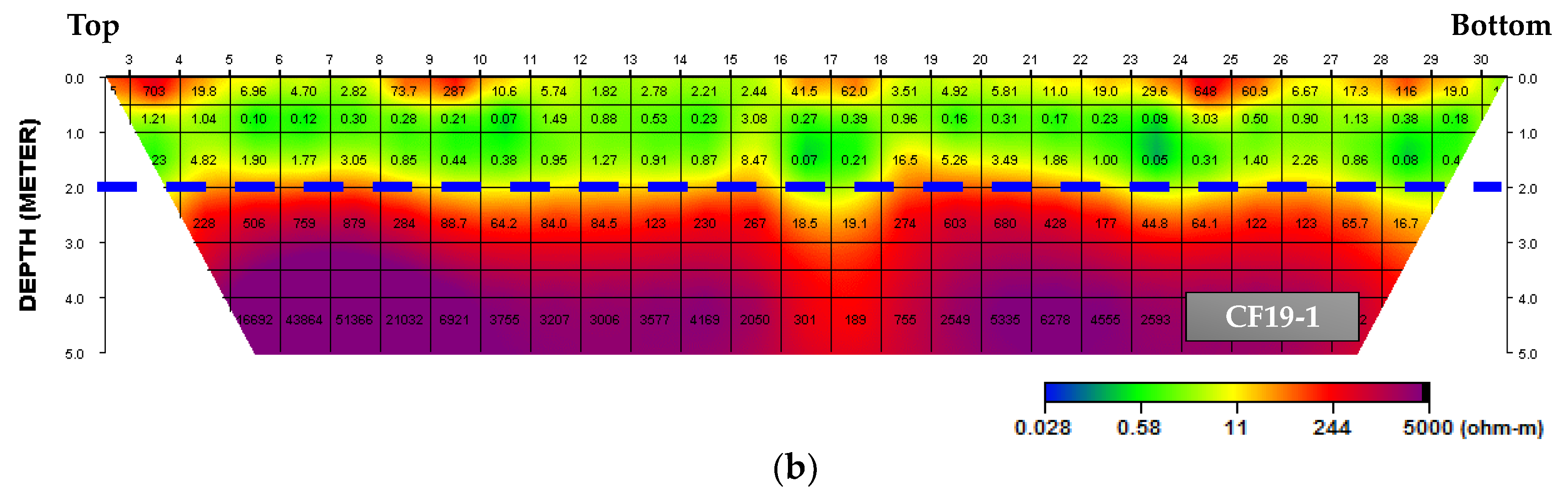
Figure 7 shows the ERT survey results of CF-13 and -19 and the cavity estimation zone using GPR. In Step 1, the thickness of the concrete face slab was 0.7–1 m, and the steel reinforcements were located at a depth 0.2–0.35 m. However, overall ERT results showed a lower resistivity range of up to 2 m in depth, the reason for which is that steel reinforcements have a greater impact. Therefore, the ERT results should be interpreted with caution in terms of depth of investigation when considering the steel reinforcements.
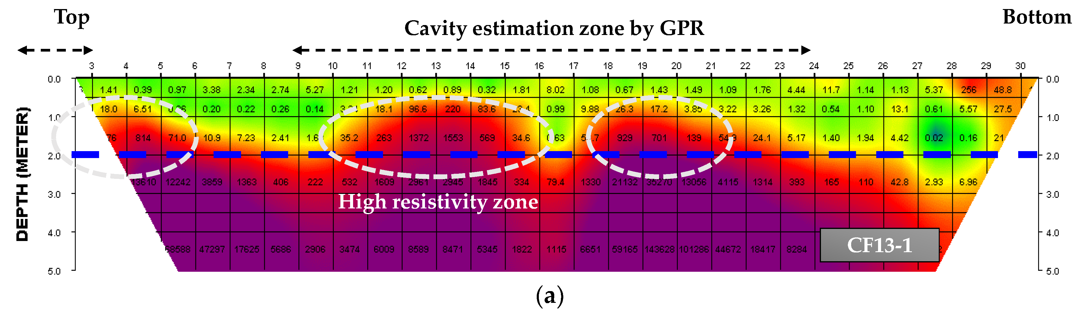
Considering the effects of the steel reinforcements, CF-13, which was in a cavity estimation zone, had a non-homogeneous high resistance effect within a depth of 2 m (
Figure 7a). In addition, it was confirmed through GPR that the high resistivity zone coincided with the cavity estimation zone. However, CF-19 without a cavity estimation zone exhibited a homogeneously low resistivity effect horizontally up to about a 2 m depth (
Figure 7b). Therefore, the effect of high resistivity within a 2 m depth can be interpreted as the possible existence of a cavity based on the ERT survey.
4.3. Correlation of Impulse Response and Electrical Resistivity Tomography Results
The correlation between the IR and ERT results were analyzed based on an electrical resistivity distribution of a 2D section, the dynamic stiffness, and the average mobility of the concrete face slab. CF-13 and -19 of step 1 were considered for all surveys of the concrete face slab. The IR survey showed that the dynamic stiffness (greater than 800 × 10
6 N/m) and average mobility (less than 0.2 × 10
−6 m/s/N) of step 1 tended to be relatively constant, but at some point an anomaly zone occurred (
Figure 5c,d). The ERT survey showed an anomaly zone with a high resistivity effect at a depth of less than 2 m. Therefore, the correlation of each survey was analyzed based on the anomaly zone, which appeared to be due to a poor concrete quality or the presence of cavities.
Figure 8 shows the IR and ERT survey results for CF-13 and -19. In
Figure 8a, the cavity estimation zone based on GPR was located at IR points 1–3 and 6–12. However, the IR points when including the IR and ERT results of the cavity estimation zone were 6–12. As a result of the ERT survey of IR points 6–12, it was possible to identify an anomaly zone with a high resistivity effect within a depth of 2 m. As a result of the IR survey in this section, it could be confirmed that the dynamic stiffness was low and the average mobility was higher than at the other points. Therefore, this section could predict the presence of cavities between the support layers and concrete with poor quality. In
Figure 8b, no cavity estimation zones appeared, and relatively stable parameters were shown. To compare the IR and ERT results, IR points 4–14 were analyzed. As the results of the ERT survey show, the low resistivity effect within a depth of 2 m tended to be homogeneous. As a result of the IR survey, this section did not represent the anomaly zone shown in
Figure 5. At certain points, the dynamic stiffness was low (IR point 9) and the average mobility was high (IR point 6), but the concrete was not of poor quality. Therefore, compared to CF-13, CF-19 could be confirmed from the results of the IR and ERT surveys to be a location of high-quality concrete.
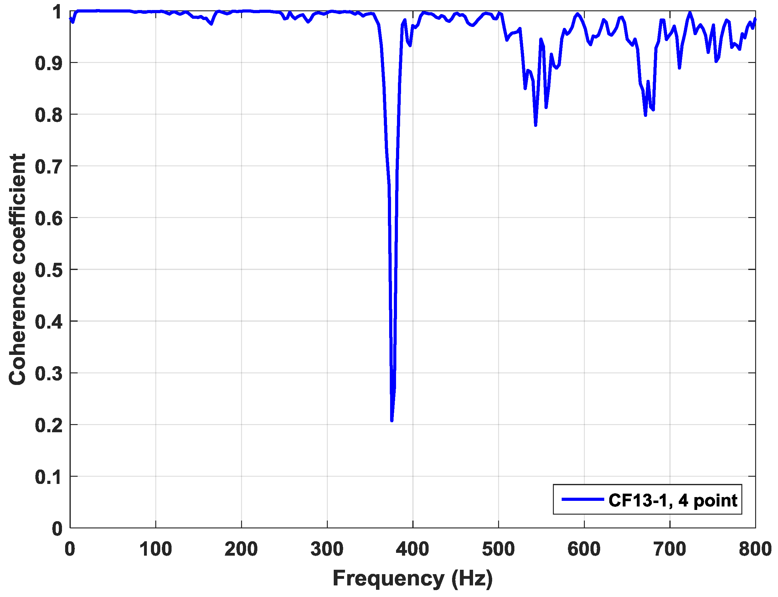
Figure 9 shows a consistency analysis of IR point 4 with the lowest dynamic stiffness at CF-13 in step 1. A consistency analysis was conducted using two measurements at the same point for statistical consistency of the frequency sounding measurement. As a result of the analysis, the coherence factor showed a high reliability with a maximum value of 0.99 and an average value of 0.96 or more. However, when the frequency was higher than 300 Hz, the coherence factor was reduced to about 0.2, and a factor of between 0.8 and 1 indicated that the reliability of the average mobility was slightly lowered. As shown in
Figure 9, the dynamic stiffness was very low, but the average mobility did not show such an anomaly. Therefore, it is expected that the average mobility will actually be higher, and poor concrete quality is expected.
5. Conclusions
IR and ERT surveys using non-destructive electrodes were applied to a concrete face slab to analyze the conditions of the concrete and investigate the presence of cavities between the underlying support layers. Unlike conventional NDT methods, an ERT survey can evaluate an area where a cavity is expected by visualizing the electrical resistivity distribution of the target object. It is also possible to analyze the vulnerability of concrete in combination with an IR survey. Each survey was analyzed by acquiring the dynamic stiffness, average mobility, and electrical resistivity distribution data using the NDT method, which could be easily measured without destroying the study object.
As the results of the IR survey indicated, step 2 showed a tendency toward a lower dynamic stiffness and higher average mobility at the bottom. This indicated the existence of a cavity or poor concrete quality between the concrete face slab and the underlying support layer. Step 1 showed a constant trend of dynamic stiffness and average mobility. However, at certain IR points, a zone judged to be an anomaly was present, and it indicated poor concrete quality. Therefore, it is possible to confirm the poor concrete quality at each step with a relatively low dynamic stiffness and high average mobility. These results indicated that a consistency analysis had high reliability and was suitable for evaluating the conditions of a concrete face slab.
The ERT survey was applied only to step 1, and the results indicated the anomaly of a high resistivity effect within a depth of 2 m. This effect was expected to be from a cavity between the concrete face slab and the underlying support layer, and was confirmed only in CF-13. In addition, it coincided with the cavity estimation zone as determined through GPR. Therefore, an ERT survey is considered suitable for investigating the presence of cavities.
As the results of the IR and ERT surveys showed, a high correlation existed between the two survey types for a cavity estimation zone because the dynamic stiffness was low and the average mobility was high in the high resistivity zone. Therefore, it is expected that cracking and a failure of the concrete face slab, as well as the loss of the underlying support layer, can be expected to be investigated in the IR and ERT method, and it is therefore appropriate to evaluate the stability of a concrete structure.
Consequentially, the application of the NDT method on a concrete face slab can provide useful information for investigating the state of the concrete and any cavities present, and it is expected that the NDT method can be used as a state and stability evaluation method for various types of concrete structures. Additionally, if it can be combined with the results of conventional NDT methods such as rebound hardness, ultrasonic pulse velocity, pull-out test, which can be applied to the assessment of the conditions of the concrete through integrated analysis of the study results, the analysis will be more confident.
Author Contributions
Investigation, J.H.; methodology, J.H.; supervision, S.O.; validation, E.I.; writing—original draft, J.H.; writing—review and editing, S.O.
Funding
This work was supported by the Nuclear Safety Research Program through the Korea Foundation Of Nuclear Safety (KoFONS) and granted financial resource from the Nuclear Safety and Security Commission (NSSC), Republic of Korea (No. 1705010).
Acknowledgments
This research was supported by the National Strategic Project, Carbon Upcycling of the National Research Foundation of Korea (NRF), funded by the Ministry of Science and ICT (MSIT), the Ministry of Environment (ME), and the Ministry of Trade, Industry, and Energy (MOTIE) (NRF-2017M3D8A2085342). This work was funded by the Korea Meteorological Administration Research and Development Program under Grant (KMI2018-09310).
Conflicts of Interest
The authors declare no conflicts of interest.
References
- Wieland, M.; Brenner, R.P. Earthquake aspects of roller compacted concrete and concrete-face rockfill dams. In Proceedings of the 13th World Conf. on Earthquake Engineering, Vancouver, BC, Canada, 1–6 August 2004. [Google Scholar]
- Szelag, M. Influence of specimen’s shape and size on the thermal cracks’ geometry of cement paste. Constr. Build. Mater. 2018, 189, 1155–1172. [Google Scholar] [CrossRef]
- Hutchinson, T.C.; Chen, Z. Improved image analysis for evaluating concrete damage. J. Comput. Civ. Eng. 2006, 20, 210–216. [Google Scholar] [CrossRef]
- Fic, S.; Szelag, M. Analysis of the development of cluster cracks caused by elevated temperatures in cement paste. Constr. Build. Mater. 2015, 83, 223–229. [Google Scholar] [CrossRef]
- Seo, M.W.; Im, E.S.; Kim, Y.S.; Ha, I.S. Centrifuge tests for simulating the behavior of CFRD with increasing water level. In Proceedings of the KGS Spring Conference, Seoul, Korea, 24-25 March 2006; pp. 784–793. [Google Scholar]
- Cheng, S.; Zhang, J. Centrifuge modeling test of dynamic response and deformation law of concrete-faced rockfill dam under different input waves. In Proceedings of the Second International Conference on Mechanic Automation and Control Engineering (MACE), Inner Mongolia, China, 15–17 July 2011; pp. 2982–2985. [Google Scholar]
- Arici, Y. Investigation of the cracking of CFRD face plates. Comput. Geotech. 2011, 38, 905–916. [Google Scholar] [CrossRef]
- Zhang, Z.; Zhao, Y.; Ge, S.; Sun, P.; Liu, C. Analysis of hollow area beneath concrete slab of seawall by means of ground penetration radar. In Proceedings of the 8th International Workshop on Advanced Ground Penetrating Radar, Florence, Italy, 7–10 July 2015; pp. 1–4. [Google Scholar]
- Arici, Y. Evaluation of the performance of the face slab of a CFRD during earthquake excitation. Soil Dyn. Earthq. Eng. 2013, 55, 71–82. [Google Scholar] [CrossRef]
- Chen, S.S.; Han, H.Q. Impact of the ‘5.12’ Wenchuan earthquake on Zipingpu concrete face rock-fill dam and its analysis. Geomech. Geoeng. 2009, 4, 299–306. [Google Scholar] [CrossRef]
- Seo, K.; Kim, Y.S. Centrifuge test for simulating behavior of CFRD during initial impoundment. J. Korean Geotech. Soc. 2007, 23, 109–119. [Google Scholar]
- Haselsteiner, R.; Ersoy, B. Seepage control of concrete faced dams with respect to surface slab cracking. In Proceedings of the 6th International Conference on Dam Engineering, Lisbon, Portugal, 15–17 February 2011; pp. 611–628. [Google Scholar]
- Ha, I.S.; Seo, M.W.; Kim, H.S. Effects of stiffness of face supporting zone on face slab behaviors of CFRD. J. Korean Soc. Civ. Eng. 2006, 26, 351–358. [Google Scholar]
- Korean Water Resources Association (KWRA). Dam Design Criteria; KWRA: Seoul, Korea, 2011. [Google Scholar]
- Korea Water Resources Corporation (K-Water). Report on the 3rd Precision Safety Diagnosis; K-Water: Deajeon, Korea, 2014. [Google Scholar]
- Davis, A.G. The non-destructive impulse response test in North America: 1985–2001. NDT&E Int. 2003, 36, 185–193. [Google Scholar]
- Chung, H.J.; Lee, H.S.; Oh, S.H.; Song, S.H. Development of the impulse response measurement system for non-destructive test of slab structure. Geophys. Geophys. Explor. 2013, 16, 45–52. [Google Scholar] [CrossRef]
- Clausen, J.S.; Zoidisand, N.; Knudsen, A. Onsite measurements of concrete structures using Impact-echo and Impulse response. In Emerging Technologies in Non-Destructive Testing V; CRC Press: Boca Raton, FL, USA, 2012; pp. 117–122. [Google Scholar]
- Layssi, H.; Ghods, P.; Alizadeh, A.R.; Salehi, M. Electrical resistivity of concrete. Concr. Int. 2015, 37, 41–46. [Google Scholar]
- Kim, J.H. DIPRO for Windows, v. 4.0.; Korea Institute of Geoscience and Mineral Resources: Daejeon, Korea, 2001. [Google Scholar]
- Clausen, J.S.; Knudsen, A. Nondestructive testing of bridge decks and tunnel linings using impulse response. In Proceedings of the 10th ACI International Conference on Recent Advances in Concrete Technology, Seville, Spain, 13–17 October 2009; SP-261-19. pp. 263–275. [Google Scholar]
Figure 1.
(a) Schematic of the concrete face rockfill dam (CFRD) that was used as the study object. The concrete face slab was located on the upstream slope and was divided into steps 1 and 2. The concrete construction time and concrete thickness of each step were different. (b) Schematic of impulse response (IR) and electrical resistivity tomography (ERT) survey lines. Each line was centrally located at CF-9, -13, -19, and -23 on the concrete face slab with a width of 15 m. The IR survey was carried out on steps 1 and 2, and the ERT survey was carried out on CF-13 and -19 of step 2.
Figure 2.
(a) Schematic of the impulse response tester. This equipment consisted of an impact hammer, a data acquisition device (DAQ) amplifier, a geophone, and a laptop PC. (b) The mobility plot of a typical concrete face slab. The dynamic stiffness was defined as the reciprocal of the slope at a frequency of less than 80 Hz. The average mobility was defined as the arithmetic mean of the mobility within the 100–800 Hz frequency range.
Figure 3.
A dipole-dipole array of a typical electrical resistivity tomography (ERT) survey. The resistivity of the study object was calculated by measuring the potential difference between two current and two potential electrodes.
Figure 3.
A dipole-dipole array of a typical electrical resistivity tomography (ERT) survey. The resistivity of the study object was calculated by measuring the potential difference between two current and two potential electrodes.
Figure 4.
(a) A schematic of the concrete model used to apply the electrical resistivity tomography (ERT) survey using non-destructive electrodes. This model was designed to investigate the effects of the steel reinforcements and cavities in the interior and bottom of the concrete. (b) ERT survey results using non-destructive electrodes, and (c) ERT results using forward modeling. In both models, the steel reinforcements showed low resistivity effects, and the cavities showed high resistivity effects.
Figure 5.
Dynamic stiffness and average mobility of the concrete face slab at CF-9, -13, -19, and -23 in steps 1 and 2. (a) The dynamic stiffness and (b) average mobility in step 2 showed a poor concrete quality owing to a low dynamic stiffness and high average mobility at the bottom (red dotted box). In step 1, (c) the dynamic stiffness was more than 800 × 106 N/m and (d) the average mobility was less than 0.2 × 10⁻⁶ m/s/N, demonstrating a constant trend but representing an unstable concrete condition at certain points.
Figure 6.
Mobility-frequency graph according to the conditions of the concrete. Impulse response (IR) point 15 of CF-23 had the highest average mobility and a low dynamic stiffness. IR point 7 of CF-13 was relatively high in dynamic stiffness and low in average mobility.
Figure 6.
Mobility-frequency graph according to the conditions of the concrete. Impulse response (IR) point 15 of CF-23 had the highest average mobility and a low dynamic stiffness. IR point 7 of CF-13 was relatively high in dynamic stiffness and low in average mobility.
Figure 7.
Results of the electrical resistivity tomography (ERT) survey of CF-13 and -19 in step 1. (a) CF-13 showed a heterogeneous high-resistivity effect in the cavity estimation zone based on ground penetrating radar (GPR). (b) CF-19 showed homogeneously low resistivity effects. Therefore, the high resistivity was expected to be due to the presence of a cavity.
Figure 8.
Impusle response (IR) and electrical resistivity tomography (ERT) survey results of CF-13 and -19 in step 1: (a) High resistivity appeared in the cavity estimation zone based on ground penetrating radar (GPR). The dynamic stiffness was relatively low, and the average mobility was high at certain points. (b) There was no cavity estimation zone and the low resistivity effect appeared to be homogeneous. In addition, the dynamic stiffness and average mobility tended to be stable.
Figure 9.
Consistency analysis results for impulse response (IR) point 4 of CF-13 in step 1.
Figure 9.
Consistency analysis results for impulse response (IR) point 4 of CF-13 in step 1.
© 2018 by the authors. Licensee MDPI, Basel, Switzerland. This article is an open access article distributed under the terms and conditions of the Creative Commons Attribution (CC BY) license (http://creativecommons.org/licenses/by/4.0/).
