Abstract
A multi-port conversion system that connects photovoltaic (PV) arrays, battery energy storage (BES), and an electric vehicle (EV) to a single-phase grid offers a flexible solution for smart homes. By integrating Vehicle-to-Grid (V2G) and Vehicle-to-Home (V2H) technologies, the system supports bidirectional energy flow, optimizing usage, improving grid stability, and supplying backup power. The proposed four-port converter consists of an interleaved bidirectional DC-DC converter for high-voltage BES, a bidirectional buck–boost DC-DC converter for EV charging and discharging, a DC-DC boost converter with MPPT for PV, and a grid-tied inverter. Its non-isolated structure ensures high efficiency, compact design, and fewer switches, making it suitable for residential applications. A state-of-charge (SoC)-based power management strategy coordinates operation among PV, BES, and EV in both on-grid and off-grid modes. It reduces reliance on EV energy when supporting V2G and V2H, while SoC balancing between BES and EV extends lifetime and lowers current stress. A 7.5 kVA system was simulated in MATLAB/Simulink to validate feasibility. Two scenarios were studied: PV, BES, and EV with V2G supporting the grid and PV, BES, and EV with V2H providing backup power in off-grid mode. Tests under PV fluctuations and load variations confirmed the effectiveness of the proposed design. The system exhibited a fast transient response of 0.05 s during grid-support operation and maintained stable voltage and frequency in off-grid mode despite PV and load fluctuations. Its protection scheme disconnected overloads within 0.01 s, while harmonic distortions in both cases remained modest and complied with EN50610 standards.
1. Introduction
Many countries worldwide are seeing considerable growth in residential solar photovoltaic (PV), battery energy storage (BES), and electric vehicles (EVs) [1]. The progress highlights a shift toward sustainable energy solutions, with significant investments in PV, BES, and EVs aimed at achieving energy security and reducing carbon emissions. According to the International Energy Agency (IEA) in [2], the global EV fleet is projected to exceed 250 million units by 2030, representing an aggregated energy storage capacity of more than 10 TWh. This enormous potential positions EVs not only as a means of transportation but also as distributed energy resources capable of supporting the grid and end-users.
The integration of Vehicle-to-Grid (V2G) and Vehicle-to-Home (V2H) technologies can transform EVs into active energy resources, rather than passive consumers; therefore, enhancing both grid stability and residential resilience [3]. V2G offers bidirectional energy flow, allowing EVs to participate in demand response, peak shaving, ancillary services such as frequency and voltage regulation, as well as facilitating renewable energy integration. These capabilities help to balance supply and demand effectively, thereby improving overall grid performance [4]. Meanwhile, V2H enables EVs to improve household/business resilience by supplying backup power during grid outages and enabling optimized energy management through smart home systems [5]. Despite these advantages, challenges such as battery degradation and user participation remain barriers to large-scale deployment.
To realize these benefits, efficient and flexible power electronic interfaces are required. Multi-port converters present an effective solution to combine those multi energy sources and the grid [6,7] which integrating sources at multiple ports can achieve weight and size reduction and efficiency improvement. Research on V2G and V2H has gained considerable attention over the last decade. Early works mainly focused on dual-port converters connecting EVs and the grid [8,9]. However, dual-port solutions lack the flexibility to integrate additional energy resources.
Three-port converters were then introduced to integrate PV or BES with EVs and the grid. A PV/EV/grid interface with V2G capabilities is proposed in [10,11], and offers significant benefits in terms of sustainable EVs and robust grid support, particularly in enhancing grid stability and integrating renewable energy. Similarly, a three-port converter that combines fuel cell/BES, EV, and grid can enhance the backup power capacity to support V2H applications [12,13]. Nonetheless, these benefits come with potential downsides such as system complexity, cost, and dependence on intermittent renewable sources.
Recently, several studies have focused on four-port converters for grid-integrated PV/BES/EV hybrid energy systems [14,15,16]. These multi-port configurations are more advantageous for integrating an increasing number of energy sources into a modern power system, which typically includes a unidirectional port for PV and three bidirectional ports for BES, EV (with V2G and V2H functionalities), and the electricity grid. Compared to dual-port or three-port designs, four-port converters offer enhanced functionality by supporting multiple bidirectional interfaces, extending backup power during outages, and improving overall efficiency. However, the existing works on four-port architectures frequently lack detailed consideration of V2G/V2H operational scenarios, as well as limited bidirectional power flow capabilities across all ports, often operating in fixed configurations with only one power flow path between ports.
Upcoming topology trends and challenges for bidirectional DC-DC and DC-AC converters are discussed in [17]. It was discovered that non-isolated DC-DC converters connect BES or EVs directly to the grid or residential loads without a galvanic isolation barrier, making them simpler and often more efficient [18]. The non-isolated configuration offers compact, higher efficiency by eliminating transformer losses, and is generally cost-effective. These benefits make them attractive for household energy applications and V2G/V2H implementations. In this work, a non-isolated four-port converter is selected to leverage these advantages, providing direct power sharing among PV, BES, EVs, and the grid with fewer conversion stages and faster dynamic response. Although the absence of isolation raises concerns regarding back-feeding and grounding, these risks are mitigated through advanced fault detection [19], the use of higher-rated components [20], and proper grounding schemes [21], ensuring compliance with safety standards such as IEEE 1547. Thus, the non-isolated architecture represents a practical trade-off, offering superior efficiency, compactness, and cost-effectiveness while maintaining safety through protective measures rather than galvanic separation.
One of the most serious concerns about V2G/V2H is the risk of increased battery degradation. As battery degradation is highly influenced by the depth of discharge (DoD) and current stress, frequent deep cycling or high rate charging/discharging can significantly decrease the number of lifetime cycles. For example, recent works in [22,23] demonstrated that increased current stress and deeper DoD are critical factors influencing lithium-ion battery aging, both fresh and second-life batteries. These stress factors, along with state of charge, cycle count, and temperature, all have an impact on battery operational efficiency and economic viability. Hence, it is important to manage the DoD of BES and EV batteries alongside managing the power flow. Power sharing, depending on the battery’s state of charge (SoC), can be an effective approach to improve battery life and reduce current stress [24]. EVs should be encouraged to provide more power to the grid or house higher than BES, due to an EV’s battery capacity (40–70 kWh) being typically much larger than that of a residential-scale BES (5–10 kWh).
Contribution: Motivated by these challenges, a single-phase four-port converter with power flow management based on SoC is implemented to support grid and home during on- and off-grid operations. The proposed non-isolated multi-port converter consists of (1) interleaved bidirectional DC-DC converter for high-voltage BES, (2) buck–boost bidirectional DC-DC converter for EV charger, (3) DC-DC boost converter with the maximum power point tracking (MPPT) for PV arrays, and (4) grid-tied DC-AC inverter to integrate with the single-phase electrical grid. The DC link voltage is controlled by the BES system which is essential for the power-balancing mechanism. The DC-AC inverter operates in grid-forming or grid-following mode through a phase lock loop (PLL) synchronization. Additionally, the SoC-based power-sharing between BES and EVs is used to avoid the high DoD during V2G and V2H operations.
The main contributions of this work are the following:
- 1.
- Design of a novel four-port topology tailored for PV/BES/EV hybrid systems with V2G and V2H functionalities, to support both on-grid and off-grid operations.
- 2.
- Development of a coordinated control strategy that ensures stable bidirectional power flow and fast dynamic response. Also, SoC-based power management can help to reduce battery degradation by reducing DoD and charge/discharge current stress.
- 3.
- Comprehensive performance evaluation through small time-step simulations, demonstrating the performance benefits of the proposed four-port converter in various operating modes.
2. Multi-Port Conversion System
The configuration of a single-phase multi-port converter is illustrated in Figure 1. Note that the direction of arrow means the positive power flow. The details of each port are as follows.
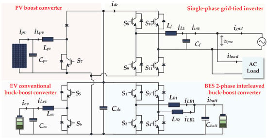
Figure 1.
A proposed single-phase four-port conversion system.
2.1. Interleaved Bidirectional DC-DC Converter for High-Voltage BES
The choice of DC-DC converter topology in a BES system depends on factors such as voltage levels, efficiency needs, cost constraints, and the desired complexity. The N-phase interleaved topologies are particularly favored in high-power applications because they distribute current evenly across multiple phases, reducing ripples and heat dissipation [25]. This leads to enhanced system efficiency, better scalability, and reduced passive component requirements, making them ideal for energy storage implementations. The basic operation of two-phase interleaved bidirectional DC-DC converter, both in charge and discharge mode, is illustrated in Figure 2.

Figure 2.
Basic operation of two-phase interleaved bidirectional DC-DC converter: (a) charging mode and (b) discharging mode.
Switches S1, S′2 and S3, S′4 are operated with a 180° phase shift and the switches on each phase (S1-S2 and S3-S4) are complementary. The change in each inductor current, , can be written as follows:
where n is 1, 2, …, N, and the symbol (′) denotes the complementary switches.
The control structure is divided into two systems: the voltage loop, which is the outer control system, and the inner loop, which is the average inductor current control system. The voltage loop regulator compares the reference DC link voltage () with the sensed voltage (), the voltage error value is eliminated by the PI controller and generates the reference battery current value () for the current loop. The block diagrams of their control are shown in Figure 3.
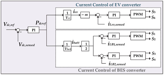
Figure 3.
BES and EV control systems with power sharing.
After is sent to the current control loop, it is split in half into the parallel circuits () which for a two-phase interleaved converter. This divided value is equal to the reference current of the inductor in each phase, and . Then, the system sends a pulse width modulation (PWM) signal to control the operation of switches to . In addition, those switches can be IGBTs, or power MOSFETs.
2.2. Buck–Boost Bidirectional DC-DC Converter for EV
The buck–boost DC-DC converter architecture was chosen to provide DC charge to EVs and give V2G/V2H capability to the grid and residential houses. This converter can step down (buck) voltage level for EV charging or step up (boost) voltage for supporting V2G/V2H function. The structure is similar to the interleave topology, but there is only one phase, making it generally simpler to design and implement when only two switches, and , are controlled. However, the current ripple is higher which requires a larger inductor. The heat and power losses are consequently increased.
The inductor current, , is regulated by PI controller as shown in Figure 3. Since the power sharing is applied to BES and EV, the DC powers contributed by BES and EV and then delivered to the DC link () are written as follows:
where is the power contribution from the BES; is the power contribution from the EV; and is a proportional gain that varies according to the SoC level of the EV battery, adjusting the power-sharing ratio.
This allows the EV to assist in supplying power based on the parameter , which determines the power-sharing ratio, as presented in Table 1. The value of ranges from 0 to 3, depending on the SoC level of the EV battery. In addition, indicates that the SoC is too low to support power, while higher values (i.e., 1, 2, or 3) offer more power-sharing contributions from the EV.

Table 1.
Power-sharing ratio of EV and BES batteries.
Although the primary power-sharing ratio is based on EV’s SoC, the BES’s SoC is monitored in parallel. The power management strategy includes conditions where the BES stops providing power support if its SoC falls below a certain threshold (e.g., 50%). In such cases, the BES only provides voltage control at the DC link, and only the PV system can deliver power to the grid and load. This indicates that while the EV’s SoC dictates the ratio of power sharing, the BES’s SoC acts as a ‘hard limit’ to prevent over-discharge and guarantee its operational reliability.
2.3. DC-DC Boost Converter with MPPT for PV
A DC-DC boost converter with MPPT algorithm is widely used in PV systems to optimize energy harvesting by raising the panel’s low voltage to a higher, stable output voltage. This design improves efficiency by adjusting the duty cycle of the boost converter to adapt to variable sunlight conditions.
The incremental conduct (IC) approach is suitable for this application since it employs the slope of the PV array power curve to determine the maximum power point (MPP), as seen in Figure 4. When the power derivative with respect to voltage () is zero, the system has reached MPP. This algorithm outperforms traditional Perturb and Observe (P&O) approaches by eliminating oscillations around MPP [26].
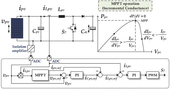
Figure 4.
The control structure of DC-DC boost converter with MPPT for PV.
The algorithm for the MPPT defines the voltage and current references, and that can extract the highest power. The and are regulated using PI controllers, resulting in a change in duty ratio (), of PMW signal to control switch .
2.4. Grid-Tied Full Bridge DC-AC Inverter
A typical single-phase grid-tied inverter consists of several key components: a DC power source, a full-bridge inverter stage for DC-AC conversion, a filter for waveform shaping, and a grid synchronization unit. The grid synchronization ensures that the inverter output matches the grid’s frequency, phase, and voltage, while the filter reduces high frequency switching noise and smooths the output waveform.
The DC-AC conversion is achieved using a full-bridge inverter circuit, which consists of four switches, to . The PWM technique is often used to refine the waveform and reduce harmonic distortion. Moreover, the LC filter, which is of low cost, easy to implement, and has a simpler design, was chosen.
The current control approach is based on the synchronous reference frame (dq), which transforms AC components in the stationary frame (αβ) to the DC signals. Steady-state errors can be eliminated by standard PI controllers. In consequence, the PI controllers output components in the dq-axes are transformed back to the αβ-axes. Only the modulation signal in the real axis mα is provided to the PWM.
Unlike the three-phase system, the single-phase system requires an extra imaginary orthogonal signal for the axis transformation. This signal is typically provided by an orthogonal signal generator (OSG), by 90° phase shifting of the measured real component. However, the OSG methods rely on filters that introduce significant signal delay, especially in tracking the fundamental component, leading to poor dynamic response.
The unbalanced synchronous reference frame technique [27] which is famous for the single-phase grid-tied inverter applications is employed as demonstrated in Figure 5. This control technique transforms control signals from the αβ axes to the dq axes without requiring the artificial quadrature signal from the OSG (extra block). In addition, the orthogonality is achieved through signal decomposition using specific transformation matrices involving the grid angle, θ, generated from the PLL.
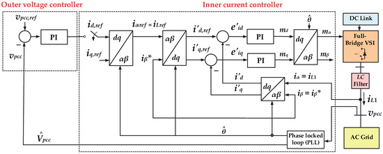
Figure 5.
The unbalanced synchronous reference frame applied in full-bridge DC-AC inverter.
The reference and feedback currents can be expressed as follows:
and
where iαref is the reference inductor current (); iα represents the feedback inductor current (iL1); and i*β is the arbitrary signal, which can be assigned as zero. The symbol (′) denotes the signals in the unbalanced synchronous reference frame.
The current error signals in dq axes, e′id and e′iq, are determined from (3) subtracted by (4), resulting in the following:
It was found that the present of i*β resulted in a zero orthogonal current error, which eiβ = 0. Applying the inverse Park transformation, the line inductor current error, eiα, can be written as follows:
where eid and eiq, are the current error components in the balanced synchronous reference frame. Substitution of (6) into (5) results in the following:
Assuming θ ≈ ωt, where ω represents the grid’s fundamental frequency. It is observed that (7) contains both DC and double-line frequency AC components. This imbalance is temporary. If the DC terms are forced to zero, the AC terms, which are oscillation components, and the physical current error will be simultaneously eliminated.
The full-bridge DC-AC inverter control is made up of an outer voltage control loop that cascades with an inner current control loop as illustrated in Figure 6a. The inductor current, , is controlled using a PI controller. During grid-support operations, only the inner current loop is engaged. The value of is adjusted according to the amount of power required from the grid. Additionally, the feed-forward compensation is also added to improve the control performance, ensuring that the inverter’s current references remain accurate despite changes in the DC link voltage.
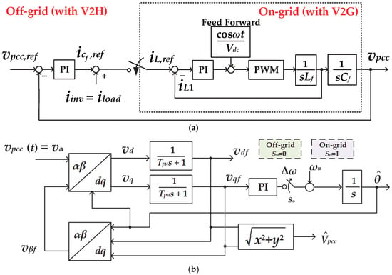
Figure 6.
The control structure of grid-tied DC-AC full bridge inverter: (a) voltage and current controls; (b) phase lock loop.
On the other hand, the outer voltage loop is only active when the grid is lost. The voltage at the point of common coupling, , is then regulated using the PI controller to keep the inverter’s output voltage at the reference value, .
Figure 6b depicts a phase lock loop (PLL) system that can operate in both on-grid and off-grid modes. A mode-selection block enables switching between these two modes using an , signal. When , it means the grid is lost and the reference frequency, , remains constant at the fundamental (i.e., 50 Hz), and there is no frequency tracking error (). However, when , the PLL performs the grid frequency tracking. The PI controller adjusts the frequency difference between the DC-AC inverter and the grid, , based on the phase difference, ensuring that the DC-AC inverter’s frequency and phase angle always synchronize with the main grid.
3. Power Management for V2G and V2H Operation Modes
The design of the multi-port converter with V2G and V2H is focused on three primary features: (1) effective power balancing, (2) intelligent power management, and (3) rigid safety protocols. These ensure that EVs can safely and efficiently contribute power back to the grid or home, enhancing energy flexibility and stability. Coordination of energy storage based on the SoC levels is required to maximize power supply to the grid or residence during both on- and off-grid operations.
Power management begins by checking the availability of each key component: EN_BES, EN_EV, EN_PV, EN_Load, and EN_Grid. Each of these symbols represents the state of an individual subsystem, indicating whether it is online and operational. When all components are enabled, the PV/BES/EV hybrid energy system proceeds to manage power flows based on load demand, PV generation, and the SoC levels of BES and EV, as illustrated in Figure 7.
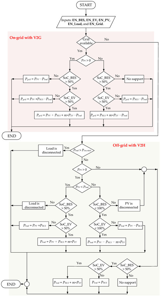
Figure 7.
Flow chart of power management system with V2G and V2H.
When EN_EV is enabled and V2G or V2H is active, the EV is ready to engage in energy management and can either charge or discharge energy according to its SoC. The power management system assesses the EV’s SoC to determine its power contribution:
- 50% > SoC_EV: The system does not allow the EV to discharge power, while the V2G or V2H function is disabled, preserving the EV’s battery for other uses.
- 50% ≤ SoC_EV < 70%: The EV provides a baseline discharge current, The EV contributes a minimal amount of energy back to the system, helping stabilize the grid or meet load demands without draining its battery too quickly.
- 70% ≤ SoC_EV < 90%: The EV discharges at a higher rate with , offering more support to the grid and load.
- 90% ≤ SoC_EV ≤ 100%: The EV provides maximum support with . This mode aims to utilize the high SoC for supporting grid and load efficiently.
3.1. On-Grid Operation with V2G
If the EN_PV, EN_Load, and EN_Grid are enabled, the PV system operates under MPPT to maximize solar generation. The DC-AC invertor’s output power, , delivered to grid and load, is the combination of power from PV, BES, and EV, respectively (). The power sharing between BES and EV is determined using Table 1. In addition, the power output of the inverter is controlled by the grid-tied DC-AC inverter, which the can be adjusted till it reaches the inverter’s rated capacity, ().
If the load demand is lower than the inverter’s rated power (), the excess power will flow back to the grid (). However, when the power generation from the PV/BES/EV hybrid energy system is not enough to meet the load demand (), the remaining power will be drawn from the grid as a supplement, ensuring a consistent energy supply.
The V2G is turned off when the SoC of EVs falls below 50%. Similarly, when the BES’s SoC falls below a certain threshold, such as 50%, it stops providing power support and only provides voltage control at the DC link. Meanwhile, when both the BES and EV hit their lower SoC limits, the system’s power management strategy dictates that they stop providing power support. In this scenario, only the PV system can deliver power to the grid and load, which .
3.2. Off-Grid Operation with V2H
When the main grid is unavailable, the PV/BES/EV hybrid energy system serves as the backup generation source to the local load or home. The DC-AC inverter switches to the grid-forming mode to keep the voltage and frequency at nominal values. The challenge of this off-grid operation is to balance power generation and demand. In addition, the BES and EV act as a power balancing tool to deal with fluctuations in PV generation and load usage.
The PV system operates at full capacity to meet demand via MPPT function. If the available power from the PV/BES/EV hybrid energy system equals or exceeds the load demand, then
- If the , the BES and EV assist the power injection to the local load, based on the power-sharing ratio in Table 1. In contrast, BES and EV absorb the surplus power from the PV generation, if and BES are not yet fully charged.
- When and BES are fully charged, the PV is then disconnected to prevent excessive power generation which may increase the system voltage and frequency. Hence, BES and EV assist energy supply with power sharing among them. The PV will resume generating power after the BES’s SoC decreases below the specific value, such as 50%.
- When the BES and EV hit their lower SoC limits, only the PV system supplies power to load.
If the power supplied by the PV/BES/EV hybrid energy system is inadequate to fulfill load demand, or if the load demand exceeds the inverter’s rated capacity (), the local load is disconnected by the built-in protection system, potentially causing a residence outage.
The PV disconnection can be achieved by suppressing the MPPT duty cycle (D), which effectively reduces or stops power extraction from the PV array. Setting D = 0 disables the main switch of the PV boost converter, causing the PV current to drop instantly to zero. This method would be a softer disconnection rather than an abrupt hardware relay opening. In addition, the PV is disconnected when (1) the BES battery is fully charged (e.g., SoC reaches 100%) and (2) the PV power generation is greater than the load demand (PPV > Pload). Once the BES’s SoC falls below a certain threshold, such as 50%, the PV will resume power generation.
4. Test System
The model of four-port conversion system integrated with PV, BES, EV, grid, and residential load, implemented in MATLAB/Simulink version 2023a software, is illustrated in Figure 8. Although power electronic converters can be simulated using specialized software such as PSCAD/EMTDC or PSIM, these platforms are costly and require extensive modeling expertise. In contrast, MATLAB/Simulink provides a cost-effective and flexible environment where the switched-circuit model of each port can be directly implemented using basic blocks and easily integrated with available control libraries [28]. This allows simultaneous modeling of converter dynamics, PWM, and control systems within a single platform, making MATLAB/Simulink particularly suitable for multi-port converter studies.
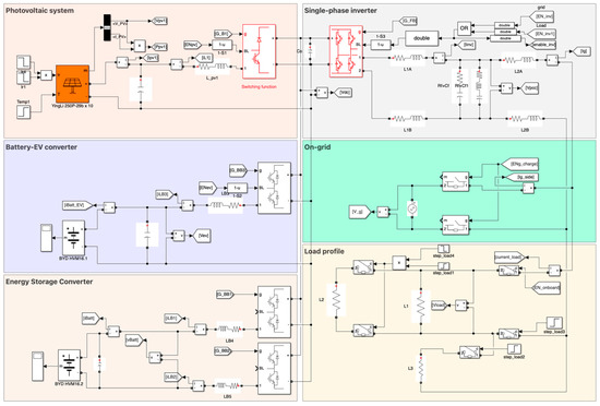
Figure 8.
The proposed four-port conversion system in MATLAB/Simulink.
The AC grid is a single-phase 220 Vrms, 50 Hz system. The resistive load can be stepped up from 6.4 kW to 12.9 kW. The PV power varies in response to solar irradiance at the maximum power point. This proposed multi-port converter has a capacity of 7.5 kVA, which is comparable to the size of a household EV charger, making it compact and suited for residential use. Assuming BES and EV batteries have SoC levels between 90% and 100%, the EV:BES power-sharing ratio becomes 3:1.
The PV system consists of ten series-connected modules, each having a maximum power of 600 W with voltage and current at the maximum power point of 35.20 V and 17.05 A, respectively. BES and EV systems use lithium-ion batteries with nominal voltages of 300 V and 400 V correspondingly. For simulation purposes, the BES and EV batteries are both assumed to have a nominal capacity of 1 Ah to align with the specified simulation timeframe.
The controller gains are designed using extended symmetrical optimization (ESO) and pole-placement techniques [29,30]. The ESO method is often used for inner current control loop. It is recommended that to have an acceptable overshoot, the PI controller should have the phase margin in the range of 30°–65° to assure the stability of the control system. The parameter β is introduced allowing designers to balance performance characteristics such as overshoot and settling time, with a recommended range of 4 to 16 to avoid excessively small or unnecessarily large phase margins. Once β is selected, the PI controller parameters, Kc and Tc, can be determined using the following relations:
where T2 is a small time constant of the plant, often representing parasitic effects, while Kp is the plant’s gain.
For the outer voltage control loop, the pole-placement technique allows for precise placement of the closed-loop poles to achieve desired transient response characteristic, such as damping ratio, ζ, and natural frequency, ωo. After ζ and ωo are chosen, the PI controller parameters, Kc and Tc, can be determined by the following:
The information for each port is as follows:
- 1.
- The interleaved DC-DC bidirectional converter has a capacity of 7 kW. The nominal battery voltage is 300 V, and the DC bus voltage is 500 V. The capacitance of BES side is 150 μF and the capacitance of DC bus is 2000 μF. Each inductance is 2 mH. The PI parameters of voltage control loop are = 13.6435 and = 0.0888, while the current control loop consists of = 0.3760 and = 0.0313. The switching frequency is 20 kHz.
- 2.
- The power rating of the buck–boost DC-DC bidirectional converter is 7 kW. The nominal EV voltage is 400 V. The capacitance of EV side is 390 μF and the inductance is 3 mH. The PI parameters of the current control loop are = 0.9219 and = 0.0768. The switching frequency is 20 kHz.
- 3.
- The capacity of the DC-DC boost converter is 6 kW. The nominal PV voltage is 400 V. At the PV side, the capacitance is 50 μF and the inductance is 2 mH. The PI parameters of voltage control loop are = 1.3329 and = 0.0178, while the current control loop consists of = 0.1633 and = 0.0136. The switching frequency is 20 kHz.
- 4.
- The grid-tied DC-AC full-bridge inverter has a rated capacity of 7.5 kW. The LC filter consists of 1 mH and 20 μF, the PI parameters of voltage control loop are = 0.3732 and = 0.0223, while the current control loop consists of = 0.6732 and = 0.0235. The switching frequency is 20 kHz. Moreover, the PI parameters of the PLL are= 0.4082 and = 0.0011, and the low pass filter time constant, , is 0.0032 s.
5. Case Studies
The performance of the proposed multi-port converter with power management system is evaluated using computer simulations on MATLAB/Simulink in two scenarios: on-grid operation with V2G and off-grid operation with V2H.
Case 1: The PV/BES/EV hybrid energy system connects to the grid and local load, trying to generate the inverter’s output power at the rated capacity (about 7.5 kW). The list of changes in PV generation and load consumption is presented in Table 2. The planned islanding transition is also added in this case by disconnecting the multi-port converter from the main grid, which BES and EV must perform the power balancing mechanism quickly to ensure the consistent energy supply for the local load. Moreover, the DC-AC inverter switches to grid-forming mode to maintain stable voltage and frequency.

Table 2.
List of events in Case 1 (On-grid operation).
The planned islanding is assigned by manually separating the main grid from the multi-port converter, without using any islanding detection techniques such as under/over voltages, frequency shifts, and rate of change in frequency. Meanwhile, the standardized thresholds for islanding detection, such as in IEEE 1547, are unnecessary and not included in this work. However, those established standards are required in the case of unintended islanding, for which automatic islanding detection is required.
Case 2: After the grid is lost, the changes in PV and load demand are listed in Table 3. To avoid residential outage, the coordinated power management between PV, BES, and EV must respond quickly while preserving the voltage and frequency required by the local load. Three conditions are investigated:

Table 3.
List of events in Case 2 (Off-grid operation).
- The BES and EV absorb the surplus PV power in the system when the load demand is less than the PV generation.
- When the load fluctuates but the inverter continues to supply power, the system must maintain reliability and stability.
- If the inverter’s power supply capacity is insufficient to supply the load demand, the multi-port converter will instantly disconnect.
To protect the converter’s power circuit from over-currents, the built-in protection system disconnects the local load when the inverter current exceeds a predefined threshold, which is often a percentage higher than the rated current. Typically, the fault current contribution from the voltage source converter is its maximum current rating. In this work, the threshold value for overcurrent protection is therefore set to the rated current/power. However, voltage and frequency protections, which are defined thresholds by established standards, are not yet included.
6. Simulation Results
6.1. Case 1: On-Grid and Islanding Operations with V2G
The results in Figure 9 show that the PV/BES/EV hybrid energy system provides grid support aiming to supply power into the grid and local load at the rated capacity of 7.5 kW. When the local load is not yet connected, EV and BES provide power into the grid with power ratio of 3:1. After the resistive load of 6.4 kW is connected at = 0.35 s, the power transferred to the grid is reduced to approximately 1.1 kW while the power sharing between EV and BES still maintains at the ratio of 3:1. It is discovered that the step response of the control system is approximately 0.05 s.
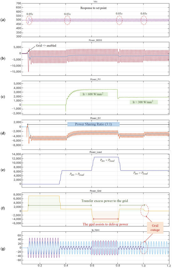
Figure 9.
Simulation results in Case 1: top to bottom (a) DC link voltage; (b) BES power; (c) PV power; (d) EV power; (e) load power; (f) grid power; (g) grid current and voltage.
The PV starts to inject power at t = 0.4 s and reaches 3.5 kW at t = 0.6 s. When PV generation increases, the system reduces the power contribution from BES and EV in order to maintain the overall power balance and ensure that the inverter’s output power matches the grid and load requirements. However, the inverter ’s output power cannot exceed the rated capacity of the grid-tied DC-AC inverter, which is 7.5 kVA. It was observed that when the PV power hits approximately 3.5 kW, the aggregated power supplied by BES and EV is then decreased to around 4 kW.
After that, at > 0.6 s, the load is stepped up to 12.9 kW which exceeds the DC-AC inverter’s rated capacity, the power from grid is suddenly brought in to support this load increase while the power from each port continues to generate as much as possible. On the other hand, at = 0.8 s, the multi-port converter can re-inject excess power into the grid once the load has been reduced below the converter rated capacity of 7.5 kW.
After the grid is disconnected at = 1.0 s, the DC-AC inverter switches to grid-forming mode to offer consistent power supply to the load. The BES and EV serve as power balancing controllers, ensuring that power generation always matches load demand. As a result, the BES and EV lower power output, making the total power output to 6.4 kW which is equivalent to the load requirement.
The output voltage and current waveforms of the DC-AC inverter are close to pure sinusoidal, with very low waveform distortion. Figure 10 demonstrates the variations in AC side currents, which include grid, load, and inverter currents, during the on- to off-grid transition. It is observed that the system continues to deliver power to load seamlessly, without interruption, when the main grid is disconnected. Meanwhile, the DC-AC inverter and PLL in grid-forming mode successfully establish the system voltage and frequency during off-grid operation.
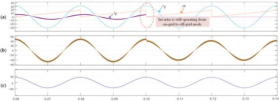
Figure 10.
AC side current waveforms in Case 1: top to bottom (a) grid current and voltage; (b) inverter current; (c) load current.
Voltage and current harmonic distortions (HDv and HDi) between the 2nd and 11th orders, in both on-grid and off-grid conditions, are illustrated in Table 4, while the total harmonic distortions of voltage and current (THDv and THDi) are calculated up to the 25th order. It was found that the HD and THD levels, both voltage and current, are relatively low and comply with standards such as EN 50160 [31] (THDv < 8% and HDv of each order < 0.5%).

Table 4.
Voltage and current harmonic distortions under on-grid and off-grid operation.
6.2. Case 2: Off-Grid Operation with V2H
The results in Figure 11 demonstrate that the power management in the multi-port converter can successfully deal with fluctuations in PV and local load during the main grid was lost. At times between 0.4 and 0.6 s, the PV power gradually increases to about 4.8 kW while the load demand is roughly 2.16 kW. It was found that at = 0.56 s, EV and BES can absorb the surplus power from PV generation, which is approximately 2.6 kW, while the EV:BES ratio is 3:1 (EV = 1.73 kW and BES = 0.86 kW). On the other hand, at = 0.6 s, EV and BES provide supplementary power, the total of which is around 1.7 kW, to assist PV generation in a case where the load demand is increased to 6.4 kW. It is found that the step response of the control system is about 0.03 s.
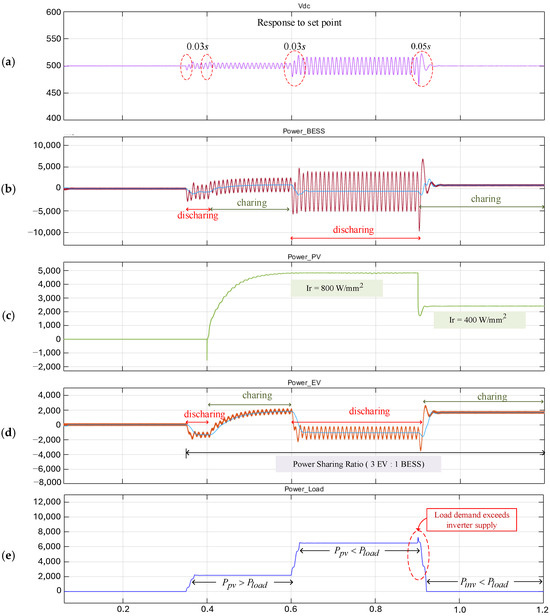
Figure 11.
Simulation results in Case 2: top to bottom (a) DC link voltage; (b) BES power; (c) PV power; (d) EV power; (e) load power.
At = 0.9 s, PV generation drops rapidly to roughly 2.5 kW, but load demand surges to nearly 12.9 kW, above the DC-AC inverter’s rated capacity of 7.5 kW. In consequence, the overcurrent is detected, and the control system quickly disconnects the local load to protect the converter’s power circuit. If the PV is still operational, even when the load is detached, the PV’s power is then used to charge batteries in EV and BES systems. It was discovered that PV power of 2.4 kW is sent to EV and BES systems at the power-sharing ratio of 3:1 (EV is 1.8 kW and BES is 0.6 kW).
This study only investigated the rapid protection performance when the overload condition occurred. Meanwhile, the automatic reconnection has not yet been explicitly implemented. Once safe conditions have been restored, the load is still manually reconnected, or the DC-AC inverter must be manually activated. The automatic reconnection may become involved when the load demand falls below the inverter-rated capacity while the system voltage and frequency remain within the statutory limits.
The waveforms of AC side currents under the overload condition are presented in Figure 12. It is found that the built-in protection system, which is part of the control system, takes a very short time (less than 0.01 s) to make a decision and issue a command to disconnect the local load when the inverter current is above the predefined threshold.
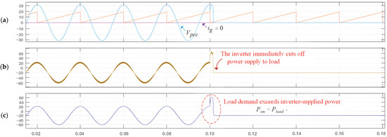
Figure 12.
AC side current waveforms in Case 2: top to bottom (a) grid current and voltage; (b) inverter current; (c) load current.
7. Discussion
The proposed multi-port converter demonstrated stable operation in both grid-connected and islanding modes. In Case 1, the system achieved reliable V2G operation, where EV and BES shared power at a 3:1 ratio, based on their SoC levels. During the planned islanding transition, the DC-AC inverter provided a seamless transition to grid-forming mode and maintained a fast transient response to ensure satisfactory voltage and frequency. Voltage and current waveforms remained close to sinusoidal with little distortion, validating the effectiveness of the PLL and inverter control loops.
In Case 2, the multi-port converter enabled V2H functions with SoC-based power sharing between EV and BES. A rapid dynamic response was achieved under various variations in load and PV generation, and the built-in protection scheme disconnected loads within <0.01 s under overcurrent conditions, safeguarding the converter without disrupting power flow continuity. The system also allowed EV and BES to absorb surplus PV power, ensuring efficient power balancing during off-grid operation.
In comparison to conventional dual or three-port systems, the proposed four-port converter offers greater flexibility by simultaneously supporting grid services and residential loads, while ensuring seamless mode transitions and rapid fault protection. These results confirm that the converter with proposed power management strategy can serve as a practical solution for smart grid integration, enhancing reliability, stability, and energy management.
To highlight the advantages of the proposed architecture, the proposed four-port converter is compared with the PV-Integrated Multifunctional Off-Board EV Charger [16], which represents one of the most advanced designs for grid-integrated PV, BES, and EV systems. Both approaches share the objective of enabling bidirectional energy exchange with the grid while supporting household or commercial loads, but their design priorities diverge significantly. A detailed comparison is provided in Table 5, summarizing the key differences in efficiency, dynamic response, battery management, complexity, and safety considerations.

Table 5.
Comparative analysis of the proposed four-port converter and related state-of-the-art solutions.
From this comparison, it is evident that the proposed four-port converter achieves a balanced trade-off, combining high efficiency, simple implementation and control, and fast dynamic response with explicit battery lifetime protection, making it a practical candidate for residential V2G/V2H applications. However, without galvanic isolation, extra protection is required to ensure safety.
8. Conclusions
A single-phase four-port conversion system with V2G and V2H functions is proposed for grid-tied PV/BES/EV hybrid energy system. Based on computer simulation, it was discovered that the multi-port converter with novel power management can successfully support grid and home during on- and off-grid operations. The results confirm that the PV/BES/EV hybrid energy system can effectively cope with fluctuations in PV generation and load demand with a rapid response (within 0.05 s). The DC-AC inverter can switch between grid-following and grid-forming modes to continue power supplying without interruptions. When the main grid fails, the bidirectional DC-DC converters in the EV and BES ports serve as vital control devices for power balancing process.
Even though EVs with V2G and V2H functions effectively support the electricity grid and providing backup power, the battery degradation is a concern due to the high DoD. To mitigate the battery degradation, power sharing between EV and BES systems, based on SoC level, is suggested to minimize DoD, resulting in longer battery life. Overall, the proposed system provides a high potential for smart home applications integrating diverse energy sources.
Despite these contributions, several limitations should be acknowledged:
- (1)
- The absence of a detailed battery aging model to quantitatively confirm the extended battery life due to SoC-based power sharing.
- (2)
- The analysis is based on MATLAB/Simulink simulations, and the absence of experimental validation restricts the verification of practical performance under real operating conditions.
- (3)
- The present work does not explicitly address the definition of standardized thresholds for islanding detection and voltage/frequency protection schemes, which may influence the reliability of transitions between grid-connected and islanded operation during unplanned islanding transition.
Future work will therefore focus on the following: (i) incorporating an advanced electrochemical battery aging model to validate the long-term benefits of the SoC-based strategy, (ii) extending this study to a hardware-in-the-loop and laboratory prototype to experimentally verify efficiency and dynamic performance, and (iii) aligning islanding detection and protection schemes with established standards such as IEEE 1547 to ensure seamless transition and safety in practical deployments.
Author Contributions
Conceptualization, C.S. and P.P.; methodology, C.S. and P.P.; software, C.S. and K.P.; validation, C.S., T.K., and P.P.; formal analysis, C.S. and K.P.; investigation, T.K., S.S., and P.P.; resources, C.S., T.K., and S.S.; data curation, C.S. and P.P.; writing—original draft preparation, C.S.; writing—review and editing, P.P.; visualization, C.S. and P.P.; supervision, S.S.; project administration, P.P.; funding acquisition, P.P. All authors have read and agreed to the published version of the manuscript.
Funding
This research was funded by Naresuan University (Thailand), grant number R2567C029.
Data Availability Statement
The data presented in this study are available on request from the corresponding author.
Acknowledgments
This work is part of the “Power flow controller for mobile Electric Vehicle charger integrated with Photovoltaic and High-voltage battery” project (grant number R2567C029) supported by Naresuan University, Thailand. Our gratitude also goes to the Smart Electric Power Conversion Laboratory (Sepcon) and the Centre of Excellence on Energy Technology and Environment (CeTe) for providing the facilities needed to conduct this study.
Conflicts of Interest
The authors declare no conflicts of interest.
Nomenclature
| Abbreviations | |
| BES | Battery Energy Storage |
| DoD | Depth of Discharge |
| EV | Electric Vehicle |
| IC | Incremental Conductance (MPPT technique) |
| MPPT | Maximum Power Point Tracking |
| P&O | Perturb and Observe (MPPT technique) |
| PI | Proportional-Integral Controller |
| PLL | Phase Locked Loop |
| PWM | Pulse Width Modulation |
| PV | Photovoltaic |
| SoC | State of Charge |
| V2G | Vehicle-to-Grid |
| V2H | Vehicle-to-Home |
| Symbols | |
| Battery capacitance | |
| DC bus capacitance | |
| EV side capacitance | |
| PV side capacitance | |
| Duty ratio of PMW signal | |
| Reference battery current | |
| Reference EV current | |
| Inductor current for PV boost converter | |
| Reference inductor current for grid-tied inverter | |
| Proportional gain of power-sharing ratio | |
| Power contribution from the BES | |
| DC link power delivered by BES and EV | |
| Power contribution from the EV | |
| Excess power flowing back to the grid | |
| Inverter’s power | |
| Inverter’s rated capacity | |
| Load demand | |
| Power from PV | |
| Switches in 2-phase interleaved bidirectional DC-DC converter | |
| Switches in buck–boost bidirectional DC-DC converter for EV | |
| Switch in DC-DC boost converter for PV | |
| Switches in grid-tied full-bridge DC-AC inverter | |
| BES voltage | |
| DC link voltage | |
| Reference DC link voltage | |
| EV voltage | |
| Voltage at the point of common coupling | |
| PV voltage reference | |
References
- International Energy Agency (IEA). World Energy Outlook 2024; IEA: Paris, France, 2024; Available online: https://www.iea.org/reports/world-energy-outlook-2024 (accessed on 14 May 2025).
- International Energy Agency (IEA). Global EV Outlook 2025; IEA: Paris, France, 2025; Available online: https://www.iea.org/reports/global-ev-outlook-2025 (accessed on 28 September 2025).
- Xu, N.Z.; Chung, C.Y. Reliability Evaluation of Distribution Systems Including Vehicle-to-Home and Vehicle-to-Grid. IEEE Trans. Power Syst. 2016, 31, 759–768. [Google Scholar] [CrossRef]
- Sora, J.; Serban, I.; Petreus, D. Enhancing Microgrid Operation through Electric Vehicle Integration: A Survey. IEEE Access 2024, 12, 64897–64912. [Google Scholar] [CrossRef]
- Lu, W. Home Energy Management Combining a Welfare Calculation and Vehicle-to-House Technique for Grid Stability. Appl. Comput. Eng. 2024, 42, 208–219. [Google Scholar] [CrossRef]
- Jiang, W.; Fahimi, B. Multiport Power Electronic Interface—Concept, Modeling, and Design. IEEE Trans. Power Electron. 2011, 26, 1890–1900. [Google Scholar] [CrossRef]
- Bhattacharjee, A.K.; Kutkut, N.; Batarseh, I. Review of Multiport Converters for Solar and Energy Storage Integration. IEEE Trans. Power Electron. 2019, 34, 1431–1445. [Google Scholar] [CrossRef]
- Panchanathan, S.; Vishnuram, P.; Rajamanickam, N.; Bajaj, M.; Blazek, V.; Prokop, L.; Misak, S. A Comprehensive Review of the Bidirectional Converter Topologies for the Vehicle-to-Grid System. Energies 2023, 16, 2503. [Google Scholar] [CrossRef]
- Tasnim, M.N.; Riana, J.M.K.; Shams, T.; Shahjalal, M.; Subhani, N.; Ahmed, M.R.; Iqbal, A. A Critical Review on Contemporary Power Electronics Interface Topologies to Vehicle-to-Grid Technology: Prospects, Challenges, and Directions. IET Power Electron. 2024, 17, 157–181. [Google Scholar] [CrossRef]
- Acharige, S.S.G.; Haque, M.E.; Arif, M.T.; Hosseinzadeh, N.; Saha, S. A Solar PV Based Smart EV Charging System with V2G Operation for Grid Support. In Proceedings of the 2021 31st Australasian Universities Power Engineering Conference (AUPEC), Perth, Australia, 26–30 September 2021; pp. 1–6. [Google Scholar] [CrossRef]
- Nikhare, Y.; Kumar, J.; Samanta, S. A Smart Three-Port Converter for Interconnecting Grid, EV, and Solar-PV for Enhancing System Performance. In Proceedings of the 2023 IEEE Energy Conversion Congress and Exposition (ECCE), Nashville, TN, USA, 29 October–2 November 2023; pp. 39–46. [Google Scholar] [CrossRef]
- Lai, C.-M.; Pan, M.-H.; Chen, Z.-M. A Multi-Port Power Converter with High Voltage Gain. In Proceedings of the 2024 6th International Conference on Electrical, Control and Instrumentation Engineering (ICECIE), Pattaya, Thailand, 19–21 January 2024; pp. 1–6. [Google Scholar] [CrossRef]
- Savrun, M.M.; Inci, M.; Büyük, M. Design and Analysis of a High Energy Efficient Multi-Port DC–DC Converter Interface for Fuel Cell/Battery Electric Vehicle-to-Home (V2H) System. J. Energy Storage 2022, 45, 103755. [Google Scholar] [CrossRef]
- Firdous, Z.; Mekhilef, S.; Mubin, M.B.; Siddique, M.D.; Elsanabary, A.; Ab Aziz, N.F.; Seyedmahmoudian, M.; Stojcevski, A. Multiport Converters Based EV Charging: Architectures, Challenges, Performance Analysis and Emerging Trends. In Proceedings of the 2023 IEEE International Conference on Energy Technologies for Future Grids (ETFG), Wollongong, NSW, Australia, 3–6 December 2023. [Google Scholar]
- Khan, O.; Hredzak, B.; Fletcher, J.E. A Reconfigurable Multiport Converter for Integrated PV/EV/Battery Systems. IEEE Open J. Power Electron. 2025, 6, 811–829. [Google Scholar] [CrossRef]
- Lenka, R.K.; Panda, A.K.; Patel, R.; Guerrero, J.M. PV Integrated Multifunctional Off-Board EV Charger with Improved Grid Power Quality. IEEE Trans. Ind. Appl. 2022, 58, 5520–5532. [Google Scholar] [CrossRef]
- Chaitanya, M.K.; Vinayak, A.S.; Pavan, B.J.G.; Lakshmi, N.N.; Sandeep, K. A Review of Bidirectional DC–DC and DC–AC Converters for V2G and G2V Applications. In Proceedings of the 2023 International Conference on Power, Instrumentation, Energy and Control (PIECON), Chennai, India, 10–12 February 2023. [Google Scholar]
- Narayanaswamy, J.; Mandava, S. Non-Isolated Multiport Converter for Renewable Energy Sources: A Comprehensive Review. Energies 2023, 16, 1834. [Google Scholar] [CrossRef]
- Oliveira, C.F.; Afonso, J.L.; Monteiro, V. Fault Analysis of a Non-Isolated Three-Level DC–DC Converter Integrated in a Bipolar DC Power Grid. In Proceedings of the Sustainable Energy for Smart Cities, Cham, Switzerland, 16–18 November 2022. [Google Scholar]
- Feretti, P.H.; Tofoli, F.L.; Ribeiro, E.R. Family of Non-Isolated High Step-Up DC–DC Converters Based on the Multi-State Switching Cell. IEEE J. Emerg. Sel. Top. Power Electron. 2022, 10, 5882–5893. [Google Scholar] [CrossRef]
- Anosh, A.; Saji, D.; Jexy, A.; PG, J.; Athikkal, S. Improved Gain Non-Isolated Type DC–DC Converter. In Proceedings of the 2024 1st International Conference on Trends in Engineering Systems and Technologies (ICTEST), Kollam, India, 11–13 April 2024. [Google Scholar]
- Collath, N.; Tepe, B.; Englberger, S.; Hepp, J.; Schmitt, J.; Jossen, A.; Hesse, H.C. Aging Aware Operation of Lithium-Ion Battery Energy Storage Systems: A Review. J. Energy Storage 2022, 55, 105634. [Google Scholar] [CrossRef]
- Terkes, M.; Demirci, A.; Gokalp, E. A Comprehensive Review of the Aging Mechanism and Degradation Costs of Fresh and Second-Life Batteries Based on Analytical and Deterministic Methods. Energy Storage 2024, 6, e661. [Google Scholar] [CrossRef]
- Khalid, M.; Panigrahi, B.K. SoC-Based Decentralized Power Management in Multi-BESS-PV for EV Charging Applications. In Proceedings of the 2022 IEEE Global Conference on Computing, Power and Communication Technologies (GlobConPT), New Delhi, India, 23–25 September 2022. [Google Scholar]
- Wibisono, A.; Facta, M.; Setiawan, I. An Average Current Control Method in Multiphase Interleaved Bidirectional DC–DC Converter Connected on DC Microgrids. In Proceedings of the 2021 12th International Renewable Engineering Conference (IREC), Amman, Jordan, 14–15 April 2021. [Google Scholar]
- Prasatsap, U.; Nernchad, N.; Termritthikun, C.; Srita, S.; Kaewchum, T.; Somkun, S. Comparison of Control Configurations and MPPT Algorithms for Single-Phase Grid-Connected Photovoltaic Inverter. Adv. Electr. Comput. Eng. 2023, 23, 55–66. [Google Scholar] [CrossRef]
- Somkun, S.; Chunkag, V. Unified Unbalanced Synchronous Reference Frame Current Control for Single-Phase Grid-Connected Voltage-Source Converters. IEEE Trans. Ind. Electron. 2016, 63, 5425–5436. [Google Scholar] [CrossRef]
- Srita, S.; Somkun, S.; Kaewchum, T.; Rakwichian, W.; Zacharias, P.; Kamnarn, U.; Thongpron, J.; Amorndechaphon, D.; Phattanasak, M. Modeling, Simulation and Development of Grid-Connected Voltage Source Converter with Selective Harmonic Mitigation: HiL and Experimental Validations. Energies 2022, 15, 2535. [Google Scholar] [CrossRef]
- Preitl, S.; Precup, R.-E. An Extension of Tuning Relations after Symmetrical Optimum Method for PI and PID Controllers. Automatica 1999, 35, 1731–1736. [Google Scholar] [CrossRef]
- Åström, K.J.; Hägglund, T. PID Controllers, 2nd ed.; ISA: Research Triangle Park, NC, USA, 1995. [Google Scholar]
- EN 50160; Voltage Characteristics of Electricity Supplied by Public Distribution Networks. European Committee for Electrotechnical Standardization: Brussels, Belgium, 2022.
Disclaimer/Publisher’s Note: The statements, opinions and data contained in all publications are solely those of the individual author(s) and contributor(s) and not of MDPI and/or the editor(s). MDPI and/or the editor(s) disclaim responsibility for any injury to people or property resulting from any ideas, methods, instructions or products referred to in the content. |
© 2025 by the authors. Published by MDPI on behalf of the World Electric Vehicle Association. Licensee MDPI, Basel, Switzerland. This article is an open access article distributed under the terms and conditions of the Creative Commons Attribution (CC BY) license (https://creativecommons.org/licenses/by/4.0/).