1. Introduction
Hydrogen is one of the cleanest energy sources. The hydrogen PEMFC, which generates electric energy by the chemical reaction of hydrogen and oxygen, has been developed rapidly in recent years. As the PEMFC has the advantages of low operating temperature, high efficiency, high power density, and zero emission, its development has been strongly supported by the government and is likely to become the mainstream type of future energy structure [
1]. PEMFCs have been applied in automobiles [
2], power generation [
3], military [
4], and other fields. However, high heat production is one of the bottlenecks affecting the rapid development of PEMFC. At present, the heat production power of PEMFC is about 50%. For example, Toyota’s Mirai has an electric power of 114 kW [
5]. If the heat cannot be discharged in time, it will lead to temperature rise, proton exchange membrane dehydration, and even local hot spot perforation, which will cause safety hazards. Therefore, rapid and uniform cooling is essential to the efficient and stable operation of PEMFC.
The cooling methods of PEMFC mainly include air cooling [
6,
7], liquid cooling [
8,
9], and phase change cooling [
10,
11]. Air cooling transfers heat mainly through air forced convection, with low cooling efficiency and large application limitations [
12]. At present, liquid cooling mostly adopts a mixed solution of deionized water and glycol, and transfers heat mainly through liquid medium forced convection, which is widely used. However, liquid cooling requires a large coolant flow rate, which increases the parasitic power consumption of the cooling system. The power consumption of pumping liquid is as high as 5–10% of the power generation, and the temperature difference between the inlet and outlet of the coolant is large, resulting in the uneven internal temperature distribution in a PEMFC [
13]. The micro heat pipe is called a superconductor because of its high thermal conductivity, which uses the latent heat of vapor-liquid phase change and the sensible heat of forced convection [
14].
Silva et al. [
15] used L-shaped stainless steel tubes with stainless steel mesh core and deionized water working medium for 20W PEMFC cooling. The experiment showed that the cooling effect is excellent, and the stable working temperature of PEMFC can be controlled between 70 and 90 °C, which satisfies the heat dissipation requirements of PEMFC. It is difficult to integrate the PEMFC bipolar plate with the round tube type micro heat pipe, because PEMFC is made up of single thin sheet cells in series. Sasiwimonrit et al. [
16] established the simulation model of flat-plate heat pipe for heating and cooling of high-temperature PEMFC, which was compared with the original pad heating and forced air cooling methods. It was found that the heat pipe showed excellent performance in both heating and cooling, which improved the temperature uniformity and increased current density of the stack. Huang et al. [
13] integrated flat-plate heat pipes into PEMFC for PEMFC cooling. The experiment showed that the flat-plate heat pipes can remove the heat successfully. Compared with liquid cooling, the flat-plate heat pipe cooling shows better temperature uniformity with the PEMFC load increasing.
The pulsating heat pipe mainly transfers heat through phase change boiling of internal working fluid and vapor-liquid two-phase flow. The heat transfer mechanism is complicated, and many factors affect heat transfer power. Mehta et al. [
17] studied the optimal filling ratio and inclination angle of a flat-plate CLPHP using the acetone as a working fluid through visual experiments. It is concluded that when the filling ratio is less than 30%, a dry-out phenomenon occurs in the evaporation section and the heat transfer performance is poor. When the filling ratio is 60%, the heat transfer resistance is the smallest and the pulsating heat transfer performance is the best. When the flat-plate CLPHP is placed vertically, the internal vapor-liquid plugs oscillate faster and have the smallest thermal resistance. Chi et al. [
18] designed a pulsating heat pipe with a longer evaporation section for the heat dissipation of automotive lithium batteries and studied the effects of different filling ratios and inclination angles on the heat transfer performance through experiments. The experimental results showed that the working-fluid-filling ratio has a greater influence on the optimal heat transfer performance, and the greater the heating power, the higher the optimal volume-filling ratio. Shang et al. [
19] experimentally tested the heat transfer performance of pulsating heat pipes at different inclination angles using thermocouples and an infrared camera. The results showed that when gravity inhibits the flow of working fluid, although the temperature distribution is uniform, the thermal resistance increases. The heat transfer resistance is the smallest when placed vertically, and the heat transfer performance is the best. Senjaya et al. [
20] theoretically studied the influence of non-condensable gas on the heat transfer performance of oscillating heat pipes and compared them with other types of heat pipes. It is concluded that the existence of non-condensable gas reduces the pressure difference between the evaporation section and the condensation section so that the amplitude and frequency of internal vapor-liquid oscillation are reduced, and the heat transfer performance of the oscillating heat pipe is weakened.
At present, there are few studies on flat-plate CLPHPs used in PEMFC cooling, and the analysis of the factors affecting the heat transfer performance of CLPHPs is not clear. The closed-loop pulsating heat pipe transfers heat mainly through the latent heat of vapor-liquid phase change and forced convection sensible heat. The internal pulsation mechanism is complicated, and many factors affect its heat transfer power. This paper aims to study the thermal performance of flat-plate CLPHPs for PEMFC cooling following the requirements of PEMFC. The effects of different filling ratios, vacuum degrees, and inclination angles on the thermal resistance and internal relative pressure of CLPHP under different heat source temperatures are also studied.
2. Experimental Setup
The experimental device mainly includes a flat-plate CLPHP, a vacuum and liquid injection system, a heating system, a data acquisition system, and a cooling system. The experimental schematic diagram is shown in
Figure 1. The heat transfer of the pulsating heat pipe is mainly through the internal working fluid that absorbs heat to form a vapor-liquid plug circulation flow. The inside of the pulsating heat pipe needs to meet conditions for the formation of the vapor-liquid plug, ensuring the stable flow and heat transfer of vapor-liquid plugs. The distribution of internal vapor-liquid plugs of the pulsating heat pipe is mainly affected by the combination of gravity and surface tension. The hydraulic diameter of the internal flow channel of the pulsating heat pipe is too small, the surface tension is large, and the internal vapor-liquid working medium finds it difficult to flow. However, when the internal hydraulic diameter is large, the influence of surface tension is weakened and gravity is dominant, and it is difficult to form a stable vapor-liquid slug. The relationship between gravity and surface tension can be expressed by the dimensionless number
Bo [
21].
The theoretical hydraulic diameter of the pulsating heat pipe for a successful startup and stable operation needs to be controlled in the following range [
22].
The flat-plate CLPHP is constructed by welding two 200 mm long, 110 mm wide, and 1.2 mm thick 6061 aluminum alloy plates. The inside is a 2.3 mm × 1.4 mm rectangular flow channel with a total of 9 turns. The inner part is a binary working medium of methanol-deionized water with a mass ratio of 5:1. The height of the evaporation section, the adiabatic section, and the condensation section are 80 mm, 40 mm, and 80 mm, respectively. The evaporating section and the condensing section are respectively equipped with a set of water grooves for passing high-temperature water as the input heat source of the evaporating section, and low-temperature water as the constant cold source of the condensing section. Thermocouples (TT-T-30, accuracy 0.5 °C) are installed at the inlet and outlet of the water groove, respectively. A flow meter (LZJ-10, accuracy 2.5%) is arranged at the outlet of the heating system and the cooling system. The evaporation section, the adiabatic section, and the condensing section are each arranged with 5 thermocouples (the type is the same as above), and each thermocouple is fixed in a 0.8 mm deep micro-hole, which is distributed between the two flow channels. The thermocouple goes deep into the micro-hole to reduce temperature measurement error, and the installation position is evenly distributed in each section as far as possible. All thermocouple signals of the experimental system are recorded every 5 s by a data logger (Hioki 8423, accuracy 0.01 °C). One must record 10 times and the average values are calculated to reduce the measurement error.
Filling ratio experiment: Before filling the working fluid, the pulsating heat pipe needs to be vacuumed to discharge the internal non-condensable gas, and the vacuum gauge is used to monitor whether the vacuum is completed. Then, under the action of the internal and external pressure difference, the working fluid of different volume-filling ratios is injected by the syringe.
Inclination angle experiment: the flat-plate CLPHP is fixed on the bench, and the angle of inclination between the pulsating heat pipe and the horizontal plane is set by a protractor. The horizontal direction is defined as an angle of 0°.
Vacuum degree experiment: the vacuum pump is connected to the CLPHP, and different vacuum degrees are controlled by the vacuum gauge fixed on the liquid injection and evacuating pipeline.
During the experiments, high-temperature water with a constant temperature and stable flow rate is introduced into the evaporation section to heat the pulsating heat pipe and forced convection heat exchange through the cooling water in the condensation section. The water temperature in the evaporation section is made to rise slowly; an interval of 5 °C is set to record the temperature change, high-temperature water flow rate, and internal pressure value of each section when the pulsating heat pipe is working stably.
The pulsating heat pipe is mainly used for heat transferring through internal working medium vapor-liquid boiling condensation latent heat and forced convection sensible heat. The heat transfer power is much higher than that of pure metal and has higher thermal conductivity, and its heat transfer thermal resistance can be determined by the following formula:
where
and
can be obtained as follows:
3. Results and Discussion
The working fluid inside the CLPHP evaporation section absorbs heat, and the heat accumulation causes the temperature of the working medium to rise. The liquid working medium gradually absorbs heat and vaporizes. The internal pressure of the evaporation section gradually increases, and the pressure difference with the condensation section gradually increases. Under the action of gravity, surface tension, and pressure difference, the gradually heat-absorbing and growing vapor plug pushes the liquid slug to move through the adiabatic section to the condensation section. The temperature of the condensing section is relatively low; the vapor plug gradually releases heat and condenses, resulting in the pressure decrease and the increase of liquid plug, which returns to the evaporation section to complete the heat transfer cycle.
3.1. Filling Ratio
The small filling ratio results in a relatively high volume fraction of the internal vapor plug when CLPHP works stably; the internal pressure of CLPHP is relatively low, and the boiling point of the working fluid is relatively low. After the vapor plug absorbs heat and expands, the pressure difference required to drive a small amount of liquid plug to the condensation section is lower, so the internal pulsation startup performance is better, and the internal pulsation phenomenon is more severe. However, when the evaporation section temperature is relatively high, the liquid slug content in the evaporation section is low with a small filling ratio, and the liquid slug is mainly concentrated in the condensation section. Due to the low-pressure difference between the two sections, it is difficult for the liquid slug to reflow, resulting in dry-out, which deteriorates heat transfer performance and increases thermal resistance.
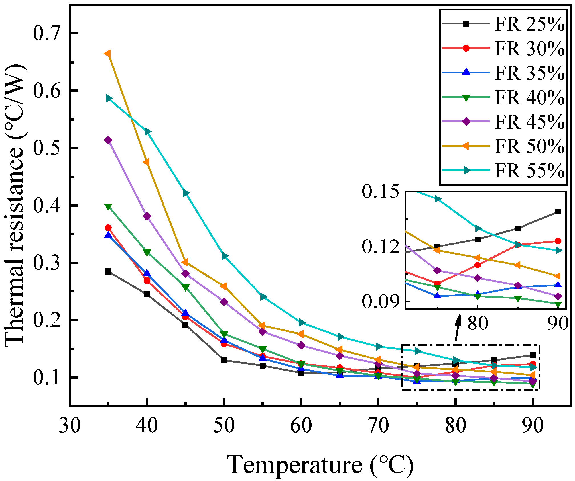
Figure 2 shows the change curve of CLPHP’s heat transfer resistance at different heating temperatures when the filling ratio is 25–55%. At a relatively low heating temperature, the thermal resistance reduces with the decrease of the internal volume-filling ratio. The thermal resistance of FR25% is the smallest, and the thermal resistance decreases, while the heating temperature increases. However, when the heating temperature is relatively high, as shown in the partially enlarged view of
Figure 2, the thermal resistance appears as a turning point, and gradually increases with the increase of the heating temperature, causing the heat transfer performance of a smaller filling ratio to deteriorate. This shows that the evaporation section of the pulsating heat pipe has a partial dry-out, which causes the internal heat transfer power to decrease. When the filling ratio is 45–55%, the heat transfer resistance at each heat source temperature increases with the increase of the filling ratio. The semi-annular and annular flow in the evaporation section has a higher heat transfer power than the slug flow, and the proportion of the internal semi-annular and annular flow in the CLPHP with a low volume-filling ratio is relatively high. For PEMFC’s ideal working temperature of 80 °C, a filling ratio of 40% has better heat transfer performance and can prevent PEMFC from deteriorating heat dissipation and causing thermal runaway.
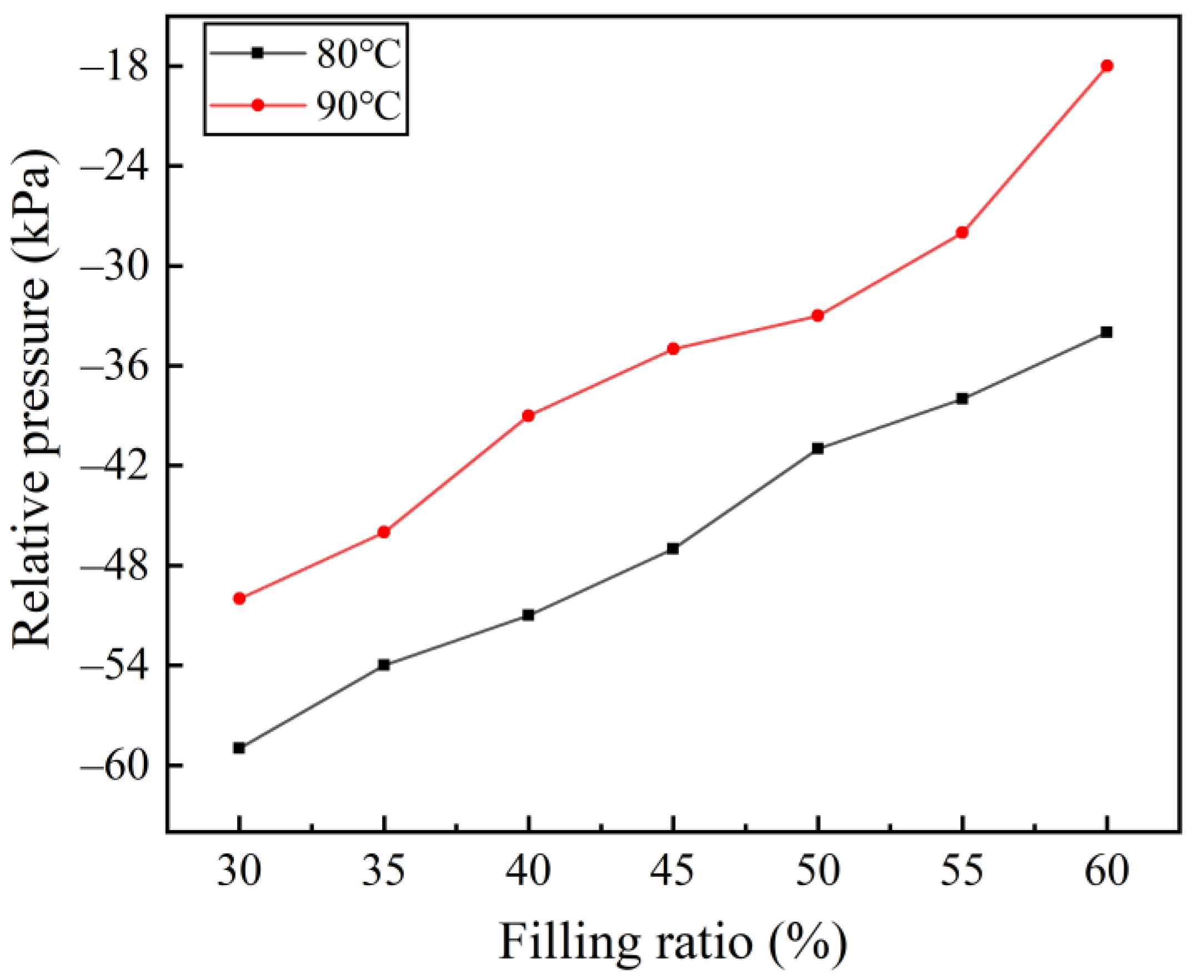
The flat-plate CLPHP is formed by merging two thin flat plates, and the degree of internal flow channel closure is affected by the internal vacuum pressure.
Figure 3 shows the change curve of the relative pressure inside CLPHP with filling ratio when the heating temperature of the evaporation section is 80 °C and 90 °C. The internal relative pressure at 90 °C is higher than that at 80 °C. As the filling ratio increases, the internal relative pressure gradually increases, and it changes approximately linearly. When the filling ratio is 40% and the evaporation section heating temperature is 90 °C, the relative pressure is -39 kpa. The lower vacuum pressure ensures the closure degree of the two plates of the flat-plate CLPHP, avoiding the plate bulging and flow channel damaging due to the positive pressure inside.
3.2. Vacuum Degree
Before CLPHP is filled with a working fluid, the internal vacuum degree determines the air content. This part of the gas does not condense and boil when CLPHP is working, as it is non-condensable gas. The non-condensable gas occupies a part of the volume, reducing the heat transfer power of CLPHP. Moreover, the vacuum degree is low, the internal relative pressure is high, and the saturated vapor pressure of the working fluid is relatively high, which is not conducive to the boiling heat transfer of the working fluid.
The thermal resistance increases with the increase of the heat source temperature in the evaporation section before CLPHP starts heat transfer. At this time, the thermal resistance is mainly affected by the thermal conductivity of the metal and the physical parameters of the working fluid. After the pulsating heat pipe starts, the thermal resistance decreases rapidly with the increase of the heat source temperature. As shown in
Figure 4, as the vacuum degree increases, the hot startup performance increases successively, and the startup heat source temperature decreases in sequence.
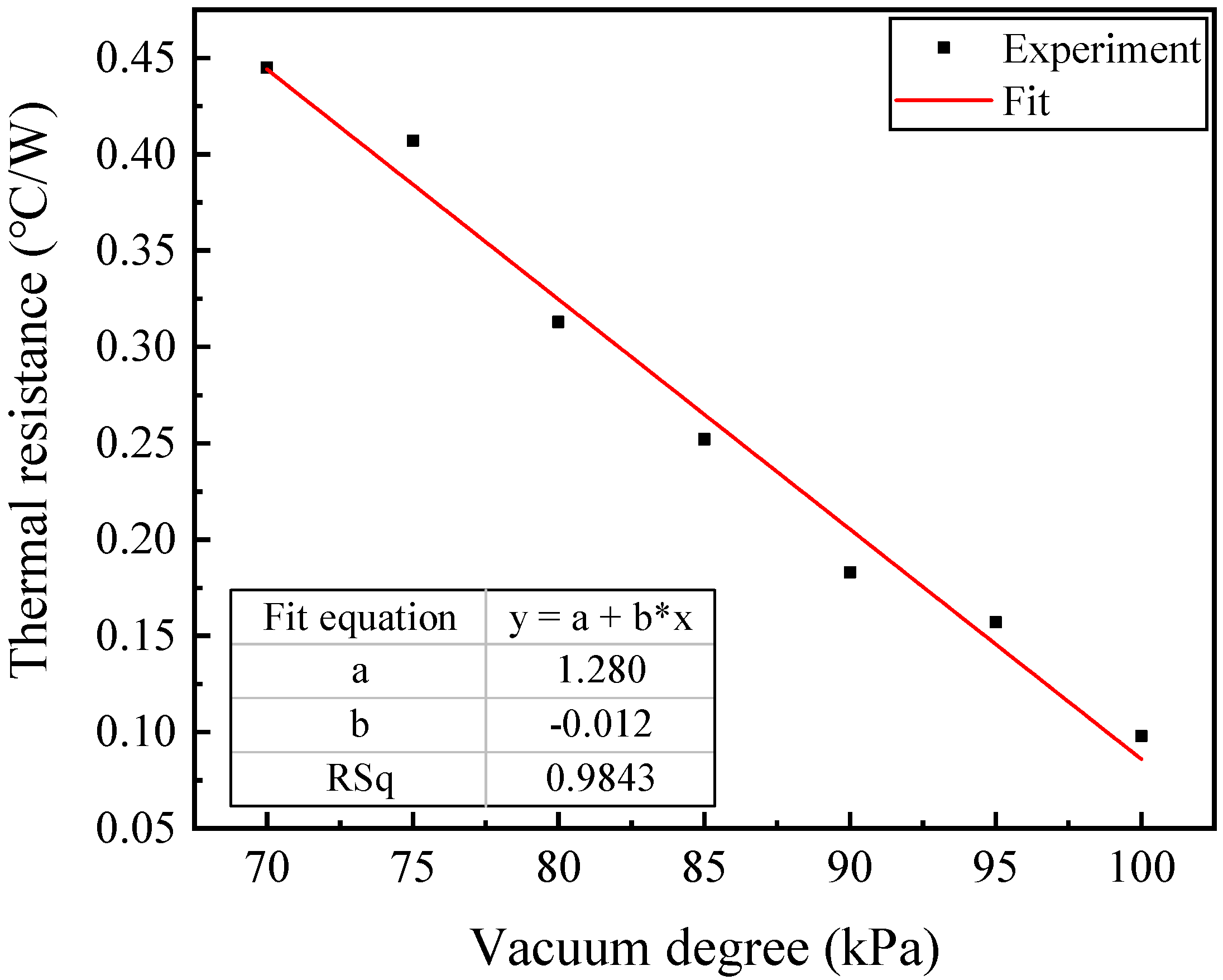
As shown in
Figure 5, when the relative pressure of the pulsating heat pipe is −95 kPa to −70 kPa before a liquid injection, then the non-condensable gas inside gradually increases, resulting in a gradual increase in the startup temperature, and the thermal resistance of the PEMFC at the ideal operating temperature of 8 °C also increases accordingly. As the degree of vacuum increases before liquid injection, the heat transfer resistance gradually decreases, and the changing trend of thermal resistance is approximately a linear decrease.
3.3. Angle of Inclination
The inclination angle between CLPHP and the horizontal ground increases the gravity component in the horizontal direction, reduces the gravity of the working fluid in the pulsating heat pipe, and increases the frictional resistance of the vapor-liquid plug flow. At the same time, due to the horizontal component of gravity, the vapor plug in the evaporation section absorbs heat and expands to reduce the resistance of the liquid slug to the condensation section. Therefore, the size of the inclination angle mainly affects the flow of the working fluid inside the CLPHP, thereby affecting its heat transfer performance.
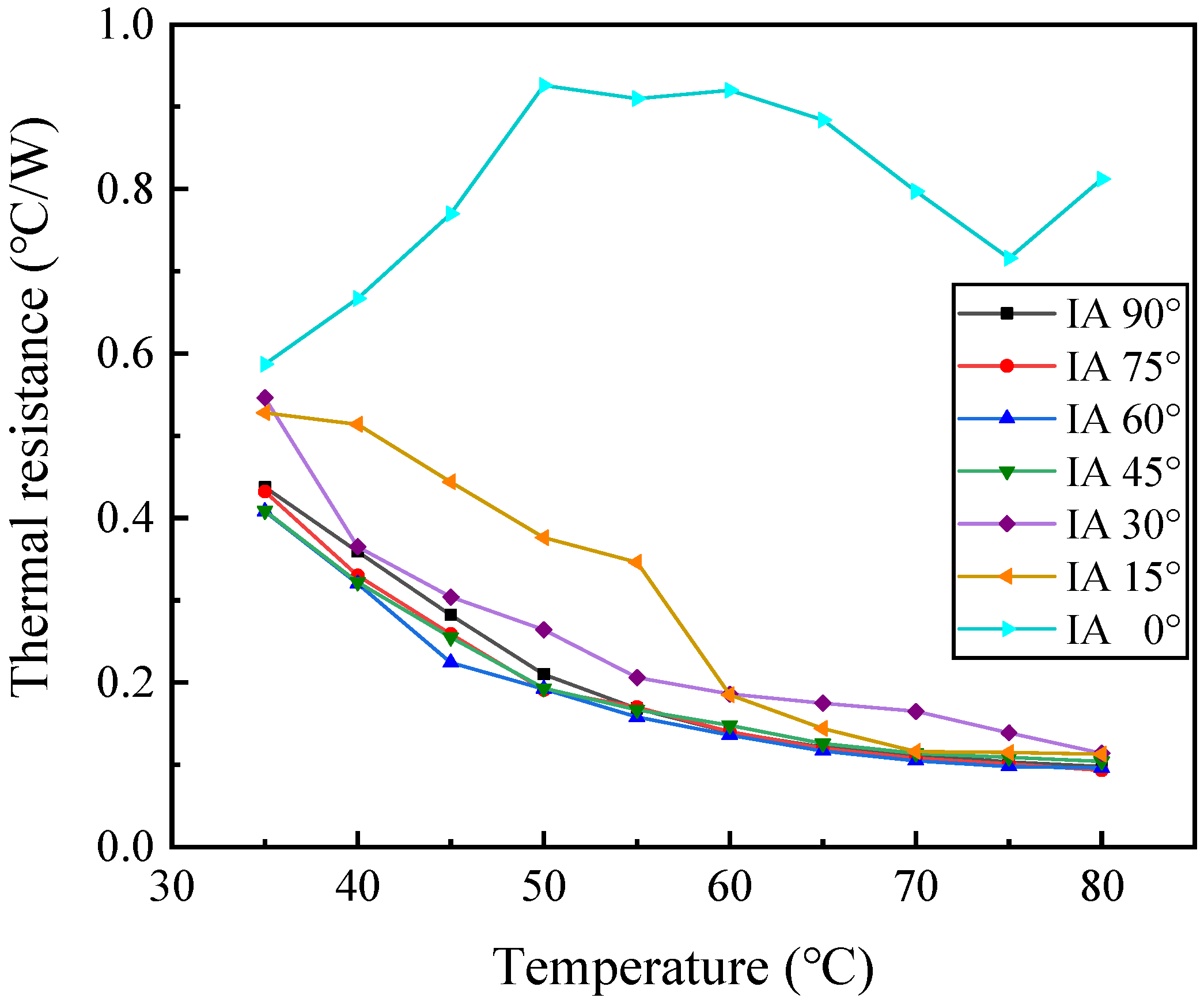
The inclination angle ranges from 0° to 90° with a 5° interval. The variation curve of heat transfer resistance with the heating temperature of the evaporation section is shown in
Figure 6. CLPHP is placed horizontally, the heat transfer resistance is always a high value, and the pulsating heat pipe cannot start normally. At lower inclination angles (15° and 30°) and relatively low evaporation section heating temperature, the thermal resistance is slightly higher than that of vertically placed CLPHP. The smaller inclination angle weakens the flow of working fluid in the pulsating heat pipe, resulting in poor startup performance of the pulsating heat pipe at low temperatures. However, when the inclination angle is 45° to 75° and the relative heat source temperature is low, the thermal resistance is lower than that of the 90° inclination angle, and the pulsating heat pipe has a better startup performance. At a higher heat source temperature, except for the 0° inclination angle, the thermal resistance of the pulsating heat pipe under stable operation is not much different. This shows that the thermal resistance of pulsating heat pipe is less sensitive to the inclination angle under stable operation at high temperatures. This characteristic ensures the heat dissipation performance of the mobile PEMFC equipped with vertically placed CLPHP cooling, even if it is under a small inclination angle and prevents the occurrence of PEMFC thermal runaway effectively.
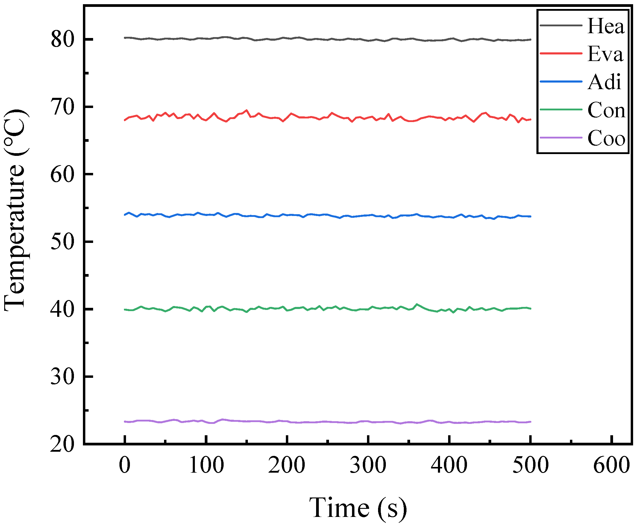
The CLPHP is placed vertically, the relative pressure is −100 kPa, the filling ratio of methanol-deionized water is 40%, the average heating (Hea) temperature of the evaporation section is 80 °C, which is the ideal working temperature of PEMFC. The temperature change at the center of each section of CLPHP at constant condensation (Coo) temperature is shown in
Figure 7. The temperatures of the evaporation section (Eva), adiabatic section (Adi), and condensing section (Con) remain stable with small fluctuations, among which the fluctuation of the evaporation section is relatively large. At this time, the heat transfer resistance of CLPHP is 0.093 ℃/W, and the heat flux is 1.59 W/cm
2. In summary, CLPHP maintains a high relative negative pressure and the internal temperature fluctuation is small when PEMFC works at the ideal temperature, which is beneficial to the stable temperature of PEMFC and ensures its safe operation.
4. Conclusions
In this study, based on the PEMFC cooling requirements, a flat-plate CLPHP was designed. The influence of volume-filling ratio, vacuum degree, and inclination angle on CLPHP’s heat transfer resistance, internal relative pressure, and temperature fluctuation was studied. The main conclusions are as follows:
- (1)
When the volume-filling ratio of CLPHP is 40%, thermal runaway can be avoided, and the heat transfer performance is better. When the ideal working temperature of PEMFC is 80 °C, the internal relative pressure is −39 kPa to avoid damaging the internal flow channel of the flat-plate CLPHP.
- (2)
A higher vacuum degree and a lower non-condensable gas content inside CLPHP contribute to a better starting performance and a lower thermal resistance. When the heat source of the evaporation section is 80 °C, the thermal resistance decreases linearly with the increase of the vacuum degree.
- (3)
It is difficult to start heat transfer for CLPHP placed horizontally. When the temperature is lower, the heat transfer performance of the lower and higher inclination angles is poor, and the inclination angle has less influence on the thermal resistance when the heating temperature is higher.
- (4)
When the heating temperature of the CLPHP evaporation section is 80 °C, the heat transfer resistance is 0.093 °C/W, the heat flux is 1.59 W/cm2, and the temperature fluctuation is small, which can ensure the stable operation of PEMFC.
Author Contributions
Conceptualization, Y.L.; methodology, Y.L.; validation, G.C.; formal analysis, Y.L.; investigation, W.Z.; data curation, G.C.; writing—original draft preparation, Y.L.; writing—review and editing, Y.L.; supervision, G.C.; project administration, G.C.; funding acquisition, G.C. All authors have read and agreed to the published version of the manuscript.
Funding
This study benefits from the financial support of the Program of Development of Major Scientific Instruments and Equipment of the State (Grant No. 2012YQ150256).
Conflicts of Interest
The authors declare no conflict of interest.
Nomenclature
| Diameter [m] | | Density [kg/m3] |
| Thermal resistance [°C/W] | Subscripts |
| Temperature [K] | | Liquid |
| Heat input [W] | | Vapor |
| Volume flow rate [m3/s] | | Inner |
| Specific heat [kJ/(kg·K)] | | Hydraulic diameter |
| Pressure [kPa] | | Inlet |
| Coefficient of determination | | Outlet |
| Bond number | | Evaporator section |
| Greek symbols | | Condenser section |
| Surface tension [N/m] | | |
| Gravity acceleration (m/s2) | | |
References
- Zhang, G.S.; Kandlikar, S.G. A critical review of cooling techniques in proton exchange membrane fuel cell stacks. Int. J. Hydrog. Energy 2012, 37, 2412–2429. [Google Scholar] [CrossRef]
- Wu, F.; Chen, B.; Pan, M. Degradation of the Sealing Silicone Rubbers in a Proton Exchange Membrane Fuel Cell at Cold Start Conditions. Int. J. Electrochem. Sci. 2020, 15, 3013–3028. [Google Scholar] [CrossRef]
- Ahmed, N.A.; Madouh, J.Y. High-frequency full-bridge isolated DC-DC converter for fuel cell power generation systems. Electr. Eng. 2018, 100, 239–251. [Google Scholar] [CrossRef]
- Krummrich, S.; Llabrés, J. Methanol reformer-The next milestone for fuel cell powered submarines. Int. J. Hydrog. Energy 2015, 40, 5482–5486. [Google Scholar] [CrossRef]
- Nonobe, Y. Development of the fuel cell vehicle mirai. IEEJ Trans. Electr. Electron. Eng. 2017, 12, 5–9. [Google Scholar] [CrossRef] [Green Version]
- Lind, A.; Yin, C.; Berning, T. A Computational Fluid Dynamics Analysis of Heat Transfer in an Air-Cooled Proton Exchange Membrane Fuel Cell with Transient Boundary Conditions. ECS Trans. 2020, 98, 255–263. [Google Scholar] [CrossRef]
- Sankar, K.; Aguan, K.; Jana, A.K. A proton exchange membrane fuel cell with an airflow cooling system: Dynamics, validation and nonlinear control. Energy Convers. Manag. 2019, 183, 230–240. [Google Scholar] [CrossRef]
- Rahgoshay, S.M.; Ranjbar, A.A.; Ramiar, A.; Alizadeh, E. Thermal investigation of a PEM fuel cell with cooling flow field. Energy 2017, 134, 61–73. [Google Scholar] [CrossRef]
- Bargal, M.H.S.; Abdelkareem, M.A.A.; Tao, Q.; Li, J.; Shi, J.P.; Wang, Y.P. Liquid cooling techniques in proton exchange membrane fuel cell stacks: A detailed survey. Alex. Eng. J. 2020, 59, 635–655. [Google Scholar] [CrossRef]
- Fly, A.; Thring, R.H. A comparison of evaporative and liquid cooling methods for fuel cell vehicles. Int. J. Hydrog. Energy 2016, 41, 14217–14229. [Google Scholar] [CrossRef] [Green Version]
- Choi, E.J.; Park, J.Y.; Kim, M.S. Two-phase cooling using HFE-7100 for polymer electrolyte membrane fuel cell application. Appl. Therm. Eng. 2019, 148, 868–877. [Google Scholar] [CrossRef]
- Ramezanizadeh, M.; Nazari, M.A.; Ahmadi, M.H.; Chen, L.G. A review on the approaches applied for cooling fuel cells. Int. J. Heat Mass Transf. 2019, 139, 517–525. [Google Scholar] [CrossRef]
- Huang, B.; Jian, Q.F.; Luo, L.Z.; Bai, X.Y. Research on the in-plane temperature distribution in a PEMFC stack integrated with flat-plate heat pipe under different startup strategies and inclination angles. Appl. Therm. Eng. 2020, 179, 115741. [Google Scholar] [CrossRef]
- Basatakoti, D.; Zhang, H.N.; Li, X.B.; Cai, W.H.; Li, F.C. Visualization of bubble mechanism of pulsating heat pipe with conventional working fluids and surfactant solution. Exp. Comput. Multiph. Flow 2020, 2, 22–30. [Google Scholar] [CrossRef] [Green Version]
- Silva, A.P.; Galante, R.M.; Pelizza, P.R.; Bazzo, E. A combined capillary cooling system for fuel cells. Appl. Therm. Eng. 2012, 41, 104–110. [Google Scholar] [CrossRef]
- Sasiwimonrit, K.; Chang, W.C. Thermal management of high-temperature polymer electrolyte membrane fuel cells by using flattened heat pipes. Therm. Sci. 2020, 135. [Google Scholar] [CrossRef] [Green Version]
- Mehta, K.; Mehta, N.; Patel, V. Experimental investigation of the thermal performance of closed loop flat plate oscillating heat pipe. Exp. Heat Transf. 2020, 34, 85–103. [Google Scholar] [CrossRef]
- Chi, R.G.; Rhi, S.H. Oscillating Heat Pipe Cooling System of Electric Vehicle’s Li-Ion Batteries with Direct Contact Bottom Cooling Mode. Energies 2019, 12, 1698. [Google Scholar] [CrossRef] [Green Version]
- Shang, F.M.; Fan, S.L.; Yang, Q.J.; Liu, J.H. An experimental investigation on heat transfer performance of pulsating heat pipe. J. Mech. Sci. Technol. 2020, 34, 425–433. [Google Scholar] [CrossRef]
- Senjaya, R.; Inoue, T. Effects of non-condensable gas on the performance of oscillating heat pipe, part I: Theoretical study. Appl. Therm. Eng. 2014, 73, 1387–1392. [Google Scholar] [CrossRef]
- Barua, H.; Ali, M.; Nuruzzaman, M.; Islam, M.Q.; Feroz, C.M. Effect of Filling Ratio on Heat Transfer Characteristics and Performance of a Closed Loop Pulsating Heat Pipe. Procedia Eng. 2013, 56, 88–95. [Google Scholar] [CrossRef] [Green Version]
- Rao, Z.H.; Wang, Q.C.; Zhao, J.T.; Huang, C.L. Experimental investigation on the thermal performance of a closed oscillating heat pipe in thermal management. Heat Mass Transf. 2017, 53, 3059–3071. [Google Scholar] [CrossRef]
| Publisher’s Note: MDPI stays neutral with regard to jurisdictional claims in published maps and institutional affiliations. |
© 2021 by the authors. Licensee MDPI, Basel, Switzerland. This article is an open access article distributed under the terms and conditions of the Creative Commons Attribution (CC BY) license (https://creativecommons.org/licenses/by/4.0/).

