Article

Research on Pressure Control Algorithm of Regenerative Braking System for Highly Automated Driving Vehicles

College of Automotive Engineering, Jilin University, Changchun 130022, China
*
Author to whom correspondence should be addressed.
World Electr. Veh. J. 2021, 12(3), 112; https://doi.org/10.3390/wevj12030112
Submission received: 14 July 2021 / Revised: 5 August 2021 / Accepted: 7 August 2021 / Published: 10 August 2021

Abstract

:
Conclusive evidence has demonstrated the critical importance of highly automated driving systems and regenerative braking systems in improving driving safety and economy. However, the traditional regenerative braking system cannot be applied to highly automated driving vehicles. Therefore, this paper proposes a fully decoupled regenerative braking system for highly automated driving vehicles, which has two working modes: conventional braking and redundant braking. Aimed at the above two working modes, this paper respectively proposes the pressure control algorithm, based on P-V characteristics, and the pressure control algorithm, based on the overflow characteristics of the solenoid valve. AMESim is utilized as the simulation platform, and then is co-simulated with MATLAB/Simulink, which is embedded with the control algorithm. The simulation results show the feasibility and effectiveness of the regenerative braking system and the pressure control algorithm.

1. Introduction

With the explosive growth of car ownership, traffic congestion, environmental pollution, and frequent accidents have become urgent problems to be solved in the current society [1,2]. In order to solve the above problems, the development of environment-friendly, safe, and intelligent vehicles has become the consensus of the automotive industry [3,4].
Applying the intelligent driving system and regenerative braking system to new energy vehicles can not only improve driving safety, but also further enhance the economy [5,6]. As the regenerative braking system is a subsystem of the intelligent driving system, it should meet the performance requirements of it. The Society of Automotive Engineering (SAE) divides the intelligent driving system into five levels. Among the five levels, level one and level two are called the driving assistance systems, where the driver still needs to participate in driving. Levels three to five are called the highly automated driving systems, where the driver does not need to be involved in driving. Vehicles equipped with level three to five intelligent driving systems are also called highly automated driving vehicles [7,8]. For the driving assistance system, it requires the regenerative braking system to have the functions of brake-by-wire and mechanical backup. For the highly automated driving system, it not only requires the regenerative braking system to realize the function of brake-by-wire, but also requires it to ensure high reliability, which means that all key functions, including the brake-by-wire, must have redundant backups, rather than a traditional mechanical backup [9].
Nowadays, many researchers have been working on designing regenerative braking systems for intelligent driving vehicles. The mechanical structure of the regenerative braking system consists of two parts: the motor braking system and the hydraulic braking system. When the vehicle is braking, the traction motor can work as a generator to produce regenerative braking torque. At the same point, the kinetic energy of vehicles is converted into electric energy to improve the total energy efficiency of the car. However, the regenerative braking torque produced by the traction motor is influenced by many factors, and on some occasions can even be zero; therefore, the regenerative braking system needs the hydraulic braking system to produce the friction braking torque, in order to fill the difference between the total braking torque and the regenerative braking torque [10,11]. At present, as the motor technology is mature enough, the research on the regenerative braking system mainly focuses on the design of the hydraulic braking system. For example, TRW Automotive developed a hydraulic braking system based on a hydraulic booster. By controlling the hydraulic booster, this system could decouple the brake pedal and brake pressure, so that the brake pressure can be adjusted electronically without pedal input [12]. Toyota Motor Corporation implemented an electro-hydraulic braking system in the Prius. This system mainly consists of a fully by-wire hydraulic control unit and a pedal stroke simulator. The hydraulic control unit is used to adjust the cylinder pressure, the pedal stroke simulator is used to decouple the brake pedal and brake pressure, as well as simulate the pedal feeling [13]. Robert Bosch GmbH developed an electric power braking system called iBooster. The working principle of this system is similar to that of the vacuum booster, but the power to push the booster piston comes from the movement of the motor, rather than the movement of the vacuum booster diaphragm. By controlling the position of the booster piston, this system could also decouple the brake pedal and brake pressure, as well as control the cylinder pressure by-wire [14]. Honda Motor Corporation installed a novel braking system on the Accord Hybrid. This system has two master cylinders, one of which is the backup master cylinder and the other is the booster master cylinder. To decouple the brake pedal and brake pressure, and control the brake pressure on each axle individually, this system is also equipped with a pedal stroke simulator [15,16]. Identical to the layout used by Honda, Continental Automotive GmbH designed an electro-hydraulic braking system called Mk C1. Compared with Honda, Mk C1 has a similar braking performance, but is more integrated [17,18].
In summary, to adjust the brake pressure independently without pedal input, all the above regenerative braking systems decouple the brake pedal and brake pressure, which shows that decoupling is a prerequisite for brake-by-wire. However, these systems can only remain decoupled in the regular state, once a single point of failure occurs, it will recouple the brake pedal and brake pressure. At this point, the driver will participate in driving to act as a mechanical backup. As a result, the above systems can only meet the requirements of the driver assistance system, and cannot be applied to highly automated driving vehicles. For highly automated driving vehicles, even if a single point of failure occurs, the driver is still not required to participate in driving, which means that its regenerative braking system must remain decoupled to achieve the brake-by-wire function in the event of failure. Since the regenerative braking system is critical to the economy and safety of highly automated driving vehicles, this paper proposes a fully decoupled regenerative braking system, based on the functional requirements of highly automated driving vehicles. This system has two working modes: conventional braking and redundant braking. When this system works normally, it is in the conventional braking mode; when a single point failure occurs, it will enter the redundant braking mode. Regardless of the working mode, this system can decouple the brake pedal and brake pressure, thus realizing the brake-by-wire function. In order to make new energy vehicles brake safely in both working modes, this paper respectively proposes the pressure control algorithm, based on P-V characteristics, and the pressure control algorithm, based on the overflow characteristics of the solenoid valve, to achieve precise control of wheel cylinder pressure under conventional braking and redundant braking.
The remainder of this paper is organized as follows. Section 2 describes the materials and methods. Section 3 presents the results and discussion. Lastly, conclusions are drawn in Section 4.

2. Materials and Methods

2.1. Regenerative Braking System

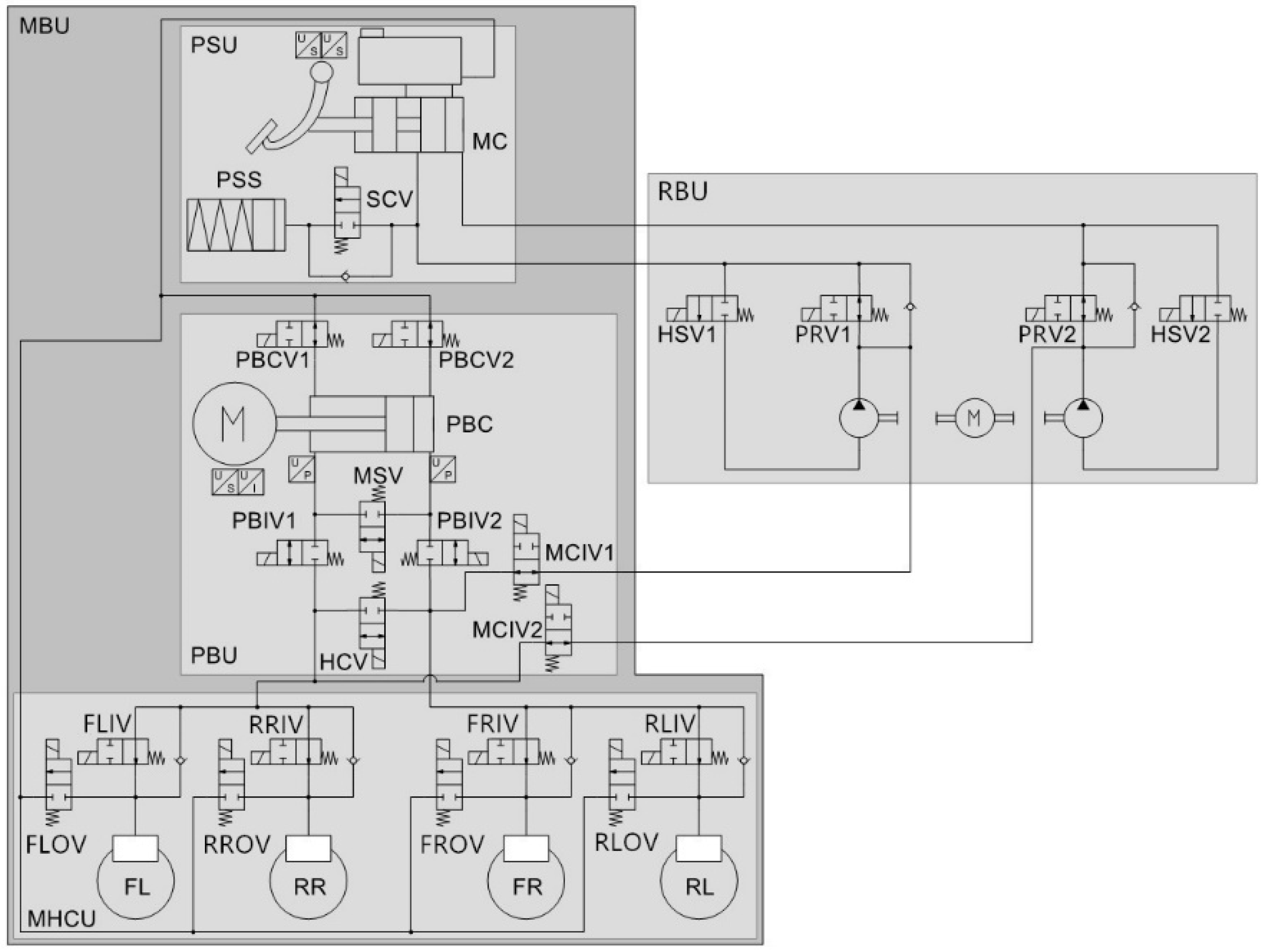
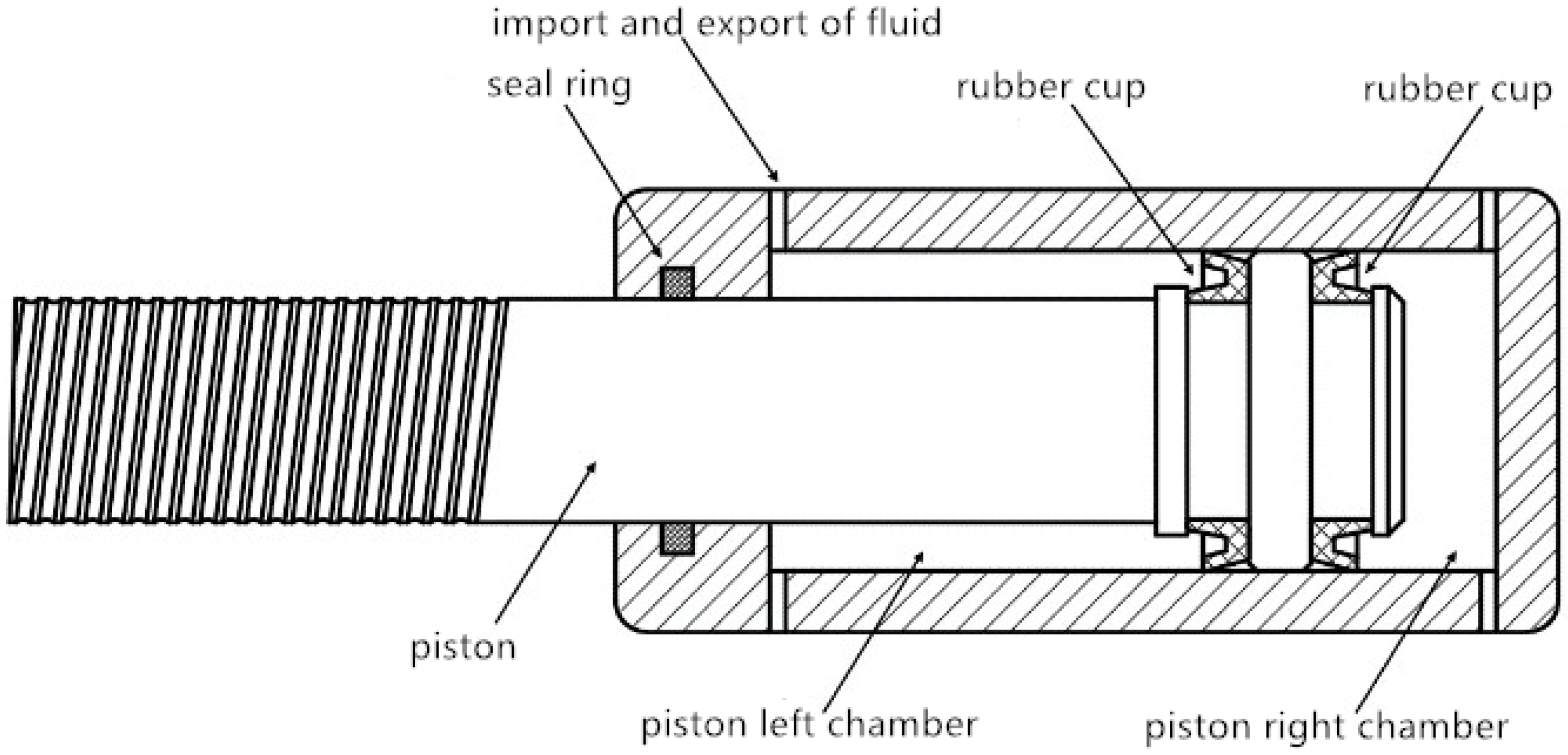
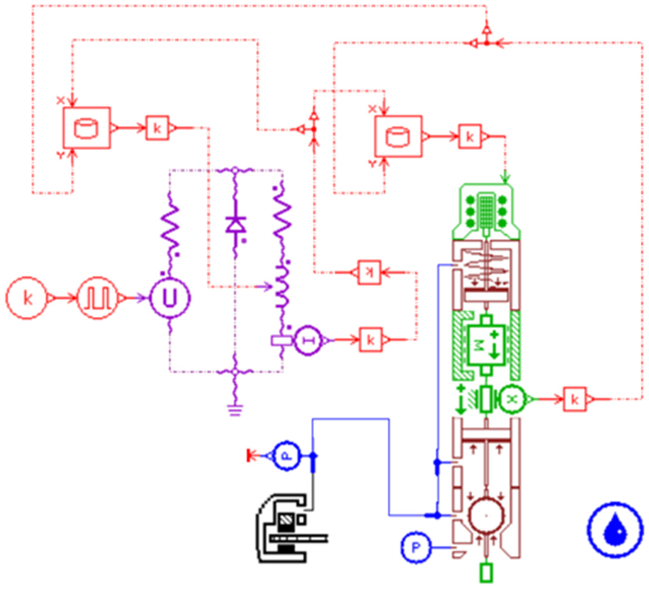
2.1.1. Mechanical Structure of the Regenerative Braking System

The mechanical structure of the regenerative braking system consists of the motor braking system and the hydraulic braking system. The motor braking system is used to generate regenerative braking torque. If the regenerative braking torque cannot meet the demand braking torque, the hydraulic braking system will fill the difference between the demand braking torque and the regenerative braking torque. Shown in Figure 1 is the structure of the hydraulic braking system, which consists of the main brake unit (MBU) and redundant brake unit (RBU). In the MBU, there are three parts: pedal simulation unit (PSU), power brake unit (PBU), and main hydraulic control unit (MHCU). The PSU includes a brake pedal, a master cylinder, a brake fluid reservoir cup, a pedal stroke simulator (PSS), and two pedal displacement sensors. The PBU includes a power brake cylinder (PBC) and several switching solenoid valves, in which two cavities of the PBC have pressure sensors, and the brushless motor driving the PBC has a rotor position sensor and a current sensor. The MHCU includes the inlet and outlet valves of each brake.
The pedal stroke simulator (PSS) consists of pistons and elastic elements. When PSS works, its internal pressure changes with the volume of the input liquid to simulate the pedal feel. The PSS is controlled by the simulator cut-off valve (SCV), which is normally a closed solenoid valve to ensure that the PSS will remain closed when the system is not powered on. The output interface of the master cylinder is directly connected with the redundant brake unit (RBU). The brake fluid flowing from the master cylinder will pass through the RBU, and the two paths of brake fluid flowing out of the RBU will respectively flow into two independent hydraulic circuits with an X-shaped arrangement through two master cylinder isolation valves (MCIV1 and MCIV2). Each independent hydraulic circuit directly drives a brake of the front and rear axle, which is equipped with a normally open solenoid valve as the inlet valve (IV), and a normally closed solenoid valve as the outlet valve (OV).
The high-pressure brake fluid in the main brake unit (MBU) comes from the power brake cylinder (PBC). Shown in Figure 2 is the structural diagram of the PBC. The PBC is driven by a brushless motor through the transmission mechanism, and the rotary motion of the motor is converted into the linear reciprocating motion of the piston, so as to realize the pressure adjustment. The PBC is equipped with six solenoid valves, which are the mode switching valve (MSV), the hydraulic connecting valve (HCV), the power brake cylinder cut-off valves (PBCV1, PBCV2), and the power brake cylinder isolation valves (PBIV1, PBIV2). The PBIV ensures that when the system is not powered on, the brake fluid will not flow into the PBC. The MSV is used to switch the pressure regulation mode of the PBC, so that the cylinder can increase and decrease pressure in different movement directions. In addition, since the PBC is not a double cavity structure, it needs to use the HCV to make PBC control the pressure of two groups of pipelines at the same time. The PBCV is used to control the connection between the PBC and the reservoir cup. It can supplement the brake fluid for the PBC or discharge the brake fluid from the PBC when the piston moves.
The redundant brake unit (RBU) is a simplified ESC hydraulic control unit, which omits the inlet valves, the outlet valves, and the low-pressure accumulators, with only the hydraulic pumps, high-pressure switching valves (HSV), and pressure regulation valves (PRV) being reserved. In the RBU, HSV is the on-off solenoid valve, which can control the opening and closing of the hydraulic pump; PRV is the linear solenoid valve, which can adjust the output pressure of the hydraulic pump. Through the control of solenoid valves and hydraulic pumps, RBU can achieve accurate brake pressure regulation, and ensure that the braking system can produce enough braking force even if the main brake unit fails.

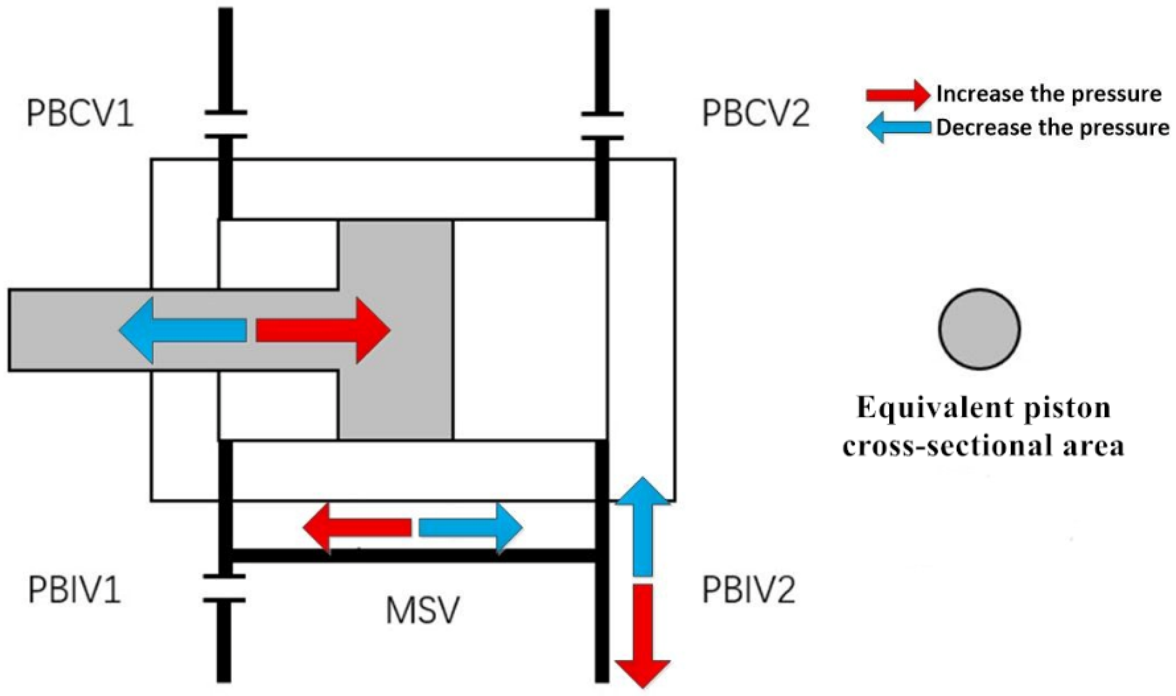
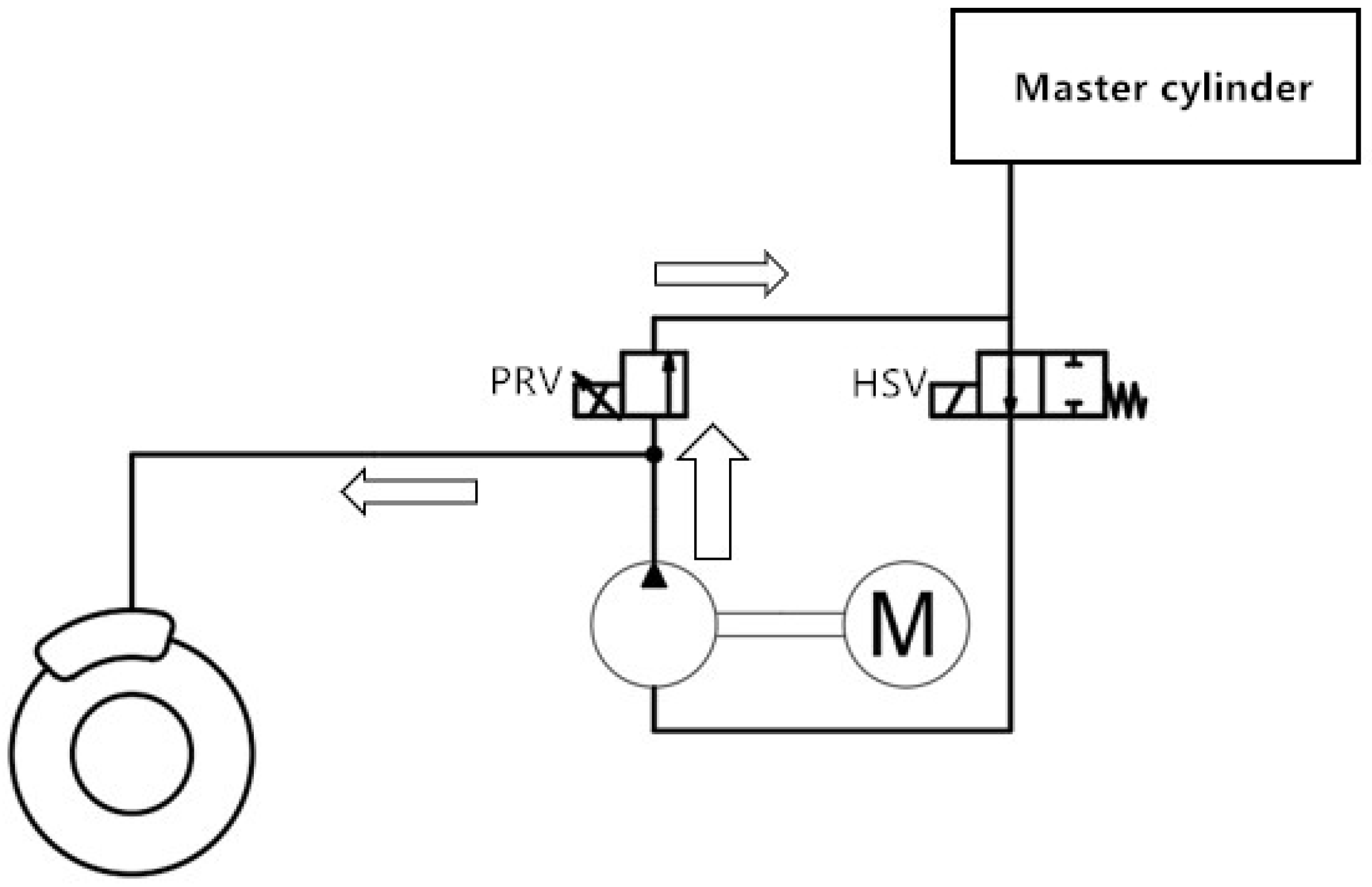
2.1.2. Working Principle of the Regenerative Braking System

The fully decoupled regenerative braking system has two working modes: conventional braking and redundant braking. When the system is in the conventional braking mode, the main brake unit (MBU) works, the regenerative braking system distributes the motor and hydraulic braking force according to the driver’s braking demand, motor battery status, and other information. In order to obtain the target hydraulic braking force, the hardware of the regenerative braking system needs to control the power brake cylinder (PBC) and solenoid valves. At this point, the hydraulic connecting valve (HCV) must open to connect two sets of independent hydraulic brake lines together, so that one PBC can control the pressure of all four brakes.
During conventional braking, the regenerative braking system has three different pressure regulation modes: high pressure, medium pressure, and low pressure. By controlling the mode switching valve (MSV), power brake cylinder cut-off valves (PBCV1, PBCV2), and power brake cylinder isolation valves (PBIV1, PBIV2), the regenerative braking system can switch between different pressure regulation modes. Shown in Figure 3, Figure 4 and Figure 5 are the flow directions of brake fluid and the action of solenoid valves under different pressure regulation modes. It can be seen that under different pressure regulation modes, the power brake cylinder (PBC) has different equivalent piston cross-sectional areas and brake fluid displacement, so the pressure regulation rate is also different. This design can reduce the performance requirements of the PBC motor and improve the pressure regulation accuracy under medium and high pressure.
The equivalent piston cross-sectional area in Figure 3, Figure 4 and Figure 5 is the cross-sectional area subjected to hydraulic pressure, which changes with the pressure regulation mode and can be calculated as follows:
A p b e = { A p i s                                                               low   pressure   mode   A p i s A r o d                                 medium   pressure   mode A r o d                                                             high   pressure   mode ,
where A p b e is the equivalent piston cross-sectional area, mm2; A p i s is the piston cross-sectional area, mm2; A r o d is the piston rod cross-sectional area, mm2.
When the main brake unit (MBU) has a single point failure, the redundant brake unit (RBU) will replace the MBU to complete the brake pressure control. In the redundant braking mode, two master cylinder isolation valves (MCIV1 and MCIV2) will be opened, and the hydraulic connecting valve (HCV) and power brake cylinder isolation valves (PBIV1, PBIV2) will be closed. The pressure control is completed by the hydraulic pumps, high-pressure switching valves (HSV), and pressure regulation valves (PRV).
When the regenerative braking system needs to be pressurized, HSV1 and HSV2 will be opened, and PRV1 and PRV2 will be closed. At this point, the hydraulic pumps pump the brake fluid into the wheel cylinders, and the pressure can be regulated by adjusting the driving current of PRV1 and PRV2. This process, including the working condition of the solenoid valves and the flow direction of the brake fluid, is shown in Figure 6.
When the regenerative braking system needs to be depressurized, PRV1 and PRV2 will be opened, HSV1 and HSV2 will be closed, and the brake fluid will flow back to the master cylinder to realize the depressurization.

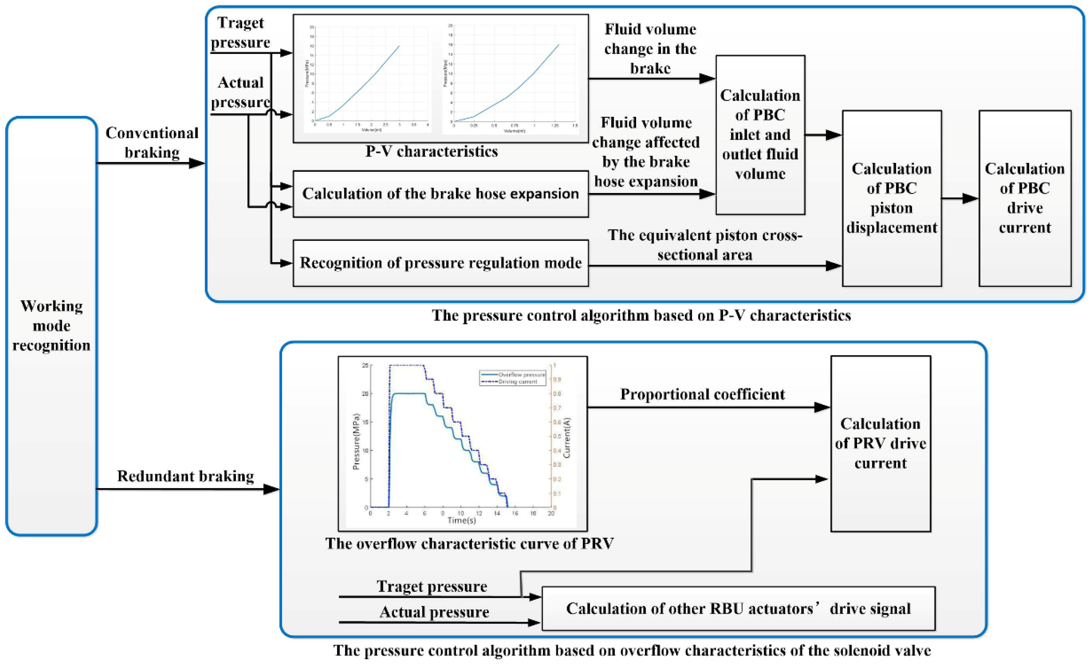
2.2. Pressure Control Algorithm

When the regenerative braking system carries out energy recovery, the hydraulic braking system needs to accurately respond to the target pressure for the vehicle braking safety [19,20]. Aiming at the two working modes of the fully decoupled regenerative braking system, this paper proposes the pressure control algorithm, based on P-V characteristics, and the pressure control algorithm, based on the overflow characteristics of the solenoid valve. The pressure control algorithm based on P-V characteristics is suitable for conventional braking mode, and the other pressure control algorithm is suitable for redundant braking mode.
Shown in Figure 7 is the schematic representation of the pressure control algorithm. When the regenerative braking system is under conventional braking mode, the required fluid volume change of the PBC is calculated first based on the P-V characteristics of wheel cylinders and the expansion characteristics of the brake hose. Then, combined with the pressure regulation mode, the required PBC piston displacement is calculated. Lastly, according to the required displacement, the drive current of the PBC motor can be obtained. When the regenerative braking system is under redundant braking mode, it can calculate the drive current of the pressure regulation valves (PRV), based on the PRV overflow characteristics. Meanwhile, the drive signals of other RBU actuators can be obtained according to the relationship between the target pressure and actual pressure.

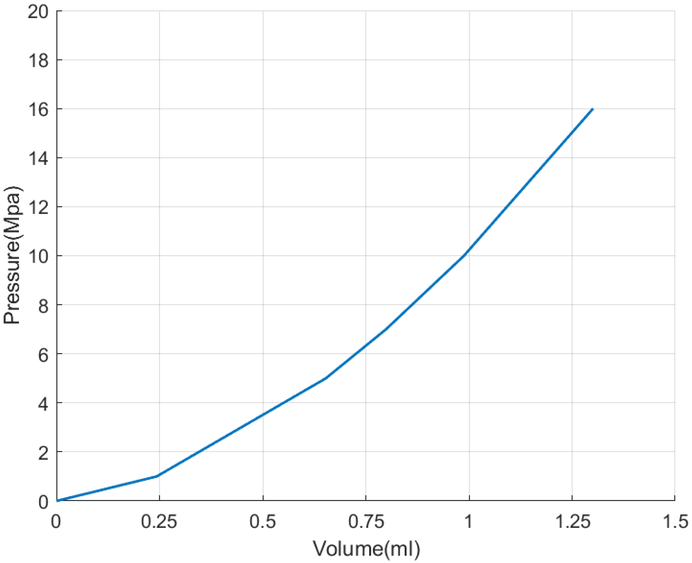
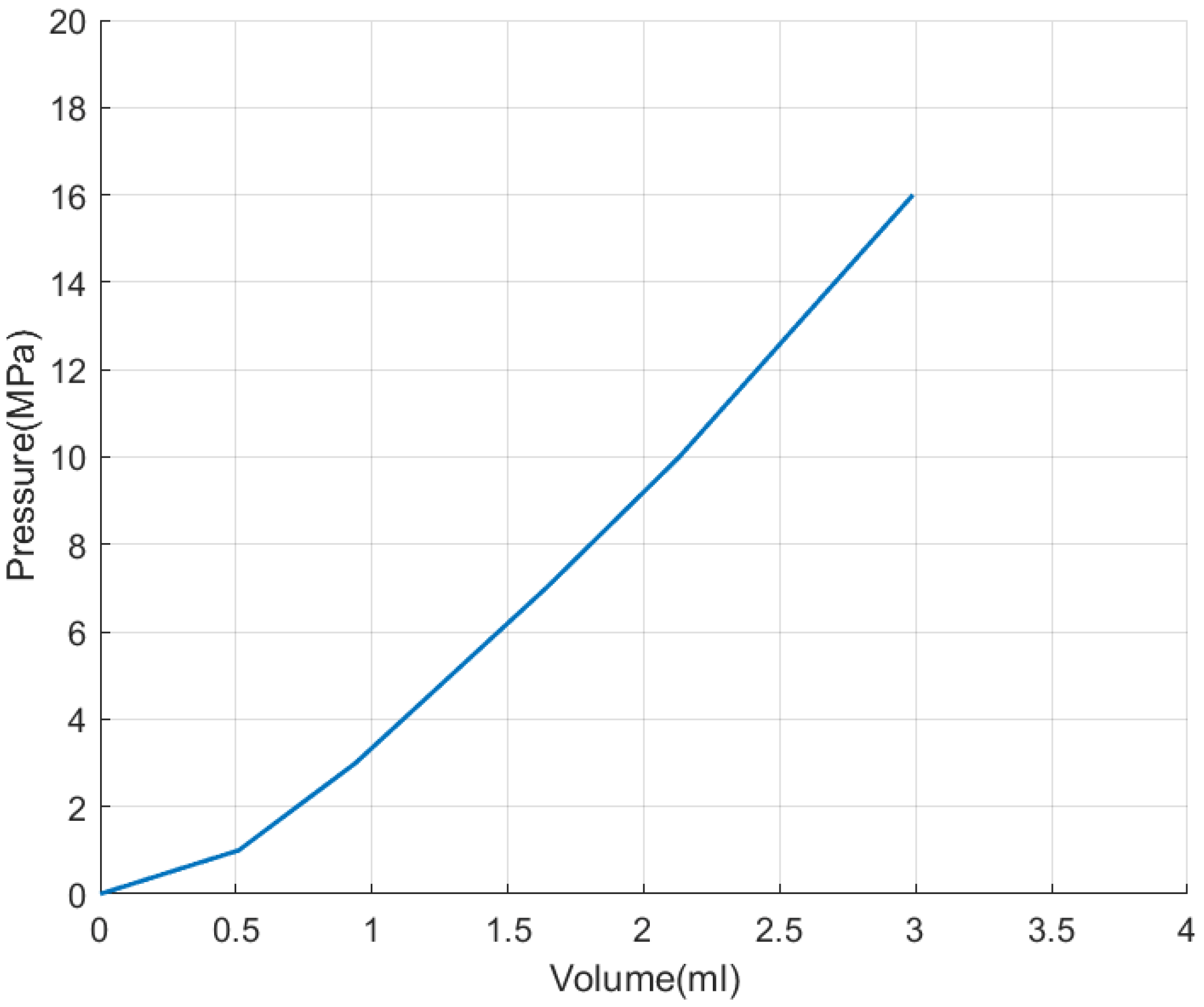
2.2.1. The Pressure Control Algorithm Based on P-V Characteristics

The power brake unit (PBU) is the main pressure source of the fully decoupled regenerative braking system. When the main brake unit (MBU) does not fail, all of the high-pressure brake fluid is generated by PBU and sent to each brake through solenoid valves and hydraulic pipelines.
In order to generate the target pressure in the brake, it is necessary to control PBU to inject a certain volume of fluid into the brake. The required brake fluid volume can be obtained by interpolating the P-V characteristic curves of the front and rear wheel brakes, as shown in Figure 8 and Figure 9. If the target pressure is P, the required volume of brake fluid for all four brakes can be calculated as follows:
  V w c ( P ) = 2 V w c 1 ( P ) + 2 V w c 2 ( P ) ,
where V w c ( P ) is the total required volume of brake fluid at pressure P, ml; V w c 1 ( P ) is the required volume of brake fluid for the front wheel brake at pressure P, ml; and V w c 2 ( P ) is the required volume of brake fluid for the rear wheel brake at pressure P, ml.
At a certain time, if the brake pressure is P t 0 and needs to be adjusted to ( P t 0 + Δ P ) , the corresponding fluid volume change in the brake is:
Δ V w c ( P t 0 , Δ P ) = V w c ( P t 0 + Δ P ) V w c ( P t 0 ) = 2 [ V w c 1 ( P t 0 + Δ P ) + V w c 2 ( P t 0 + Δ P ) 2 V w c 1 ( P t 0 ) + 2 V w c 2 ( P t 0 ) ] .
When the brake pressure changes from P t 0 to ( P t 0 + Δ P ) the volume change of brake fluid is also affected by the expansion of brake hose [21], which can be expressed as follows:
Δ V h o s e ( Δ P ) = ω h o s e Δ P ,
where Δ V h o s e ( Δ P ) is the volume change of brake fluid caused by expansion of brake hose, ml; and ω h o s e is the flexibility of the brake hose, ml/MPa.
According to Formulas (3) and (4), when the brake pressure changes from P t 0 to ( P t 0 + Δ P ) the volume of brake fluid delivered or inhaled by the power brake cylinder (PBC) can be expressed by Formula (5).
Δ V p b c ( P t 0 ,   Δ P ) = Δ V h o s e ( Δ P ) + Δ V w c ( P t 0 , Δ P ) .
The required piston displacement of PBC can be expressed as follows:
Δ x p b c ( P t 0 ,   Δ P ) = Δ V p b c ( P t 0 ,   Δ P ) A p b e .
When the PBC is working, the displacement of the PBC piston cannot be controlled directly, but it can be indirectly controlled by regulating the motor torque. With the change of displacement and cylinder pressure, the hydraulic force and friction on the piston will also change, resulting in the change of motor load torque.
When the PBC is in the pressurized state, the motion equation of the piston can be expressed as follows:
  m p b c x ¨ p b c = F p b r F p b h F f p b ,
where m p b c is the piston mass, kg; x ¨ p b c is the piston displacement, m; F p b r is the motor thrust on the piston rod, N; F p b h is the hydraulic force on piston, N; and F f p b is the friction on piston, N.
When the PBC is in the depressurized state, the motion equation of the piston can be expressed as:
  m p b c x ¨ p b c = F p b r + F p b h F f p b .
In Formulas (7) and (8), the hydraulic force and friction on the piston change with the cylinder pressure and piston displacement [22], which can be expressed as follows:
{ F p b h = A p b e P p b c F f p b = F c p b + f v p b | x ˙ p b c | ,
where P p b c is the pressure of PBC, MPa; F c p b is the coulomb friction, N; and f v p b is the coefficient of viscous friction, N/(m/s).
When the period of system control Δ t is small enough, the change in pressure can be regarded as linear. If the pressure in the power brake cylinder (PBC) changes from P t 0 to ( P t 0 + Δ P ) within Δ t , the hydraulic force on the piston at any time within Δ t can be expressed as:
  F p b h ( t ) = A p b e ( P t 0 + Δ P Δ t t ) .
Similarly, when Δ t is small enough, the change in piston speed can also be regarded as linear. Assuming that the current piston speed is x ˙ p b c 0 , then at any time within Δ t , the friction on the piston can be expressed as:
  F f p b ( t ) = F c p b + f v p b | x ˙ p b c 0 + 2 Δ x p b c ( P t 0 ,   Δ P ) t 2 t | .
Combined with Formulas (7), (10) and (11), when PBC is in the pressurized state, the acceleration of piston at any time in Δ t can be expressed as:
x ¨ p b c ( t ) = F p b r F p b h ( t ) F f p b ( t ) m p b c .
Combined with Formulas (8), (10) and (11), when PBC is in the depressurized state, the acceleration of piston at any time in Δ t can be expressed as:
x ¨ p b c ( t ) = F p b r + F p b h ( t ) F f p b ( t ) m p b c .
Since the piston needs to move Δ x p b c ( P t 0 ,   Δ P ) within Δ t , we can obtain the following relationships:
{ x ˙ p b c ( t ) = x ˙ p b c 0 + 0 t x ¨ p b c ( t ) d t Δ x p b c = 0 t x ˙ p b c ( t ) d t .
By substituting Formula (12) into Formula (14), it can be obtained that the motor thrust on the piston rod in the pressurized state is:
  F p b r = 2 m Δ x p b c t 2 2 m x p b c 0 ˙ Δ t + f v p b | x ˙ p b c 0 + 2 Δ x p b c 3 t | + F c p b + A p b e Δ P 3 + A p b e P t 0 .
By substituting Formula (13) into Formula (14), it can be obtained that the motor thrust on the piston rod in the depressurized state is:
  F p b r = 2 m Δ x p b c t 2 2 m x p b c 0 ˙ Δ t + f v p b | x ˙ p b c 0 + 2 Δ x p b c 3 t | + F c p b A p b e Δ P 3 A p b e P t 0 .
The brushless motor transforms the rotating motion into linear motion through the transmission mechanism, and the torque of the motor is transformed into the thrust of the piston rod at the same time. The power brake cylinder (PBC) described in this paper adopts two stages of transmission, the first stage is gear transmission, and the second stage is ball screw transmission. Therefore, the required motor torque can be expressed as follows:
  T p b m = F p b r I p b s 2 π η p b s i p b 0 ,
where η p b s is the ball screw efficiency; T p b m is the required motor torque, N · m; i p b 0 is the transmission ratio of the first stage gear; and I p b s is the ball screw lead, m.
According to Formula (17), the required motor torque can be obtained. The motor driver can output the target torque by controlling the stator current. If the output torque is maintained unchanged in the control period Δ t , the pressure will change to ( P t 0 + Δ P ) after Δ t .

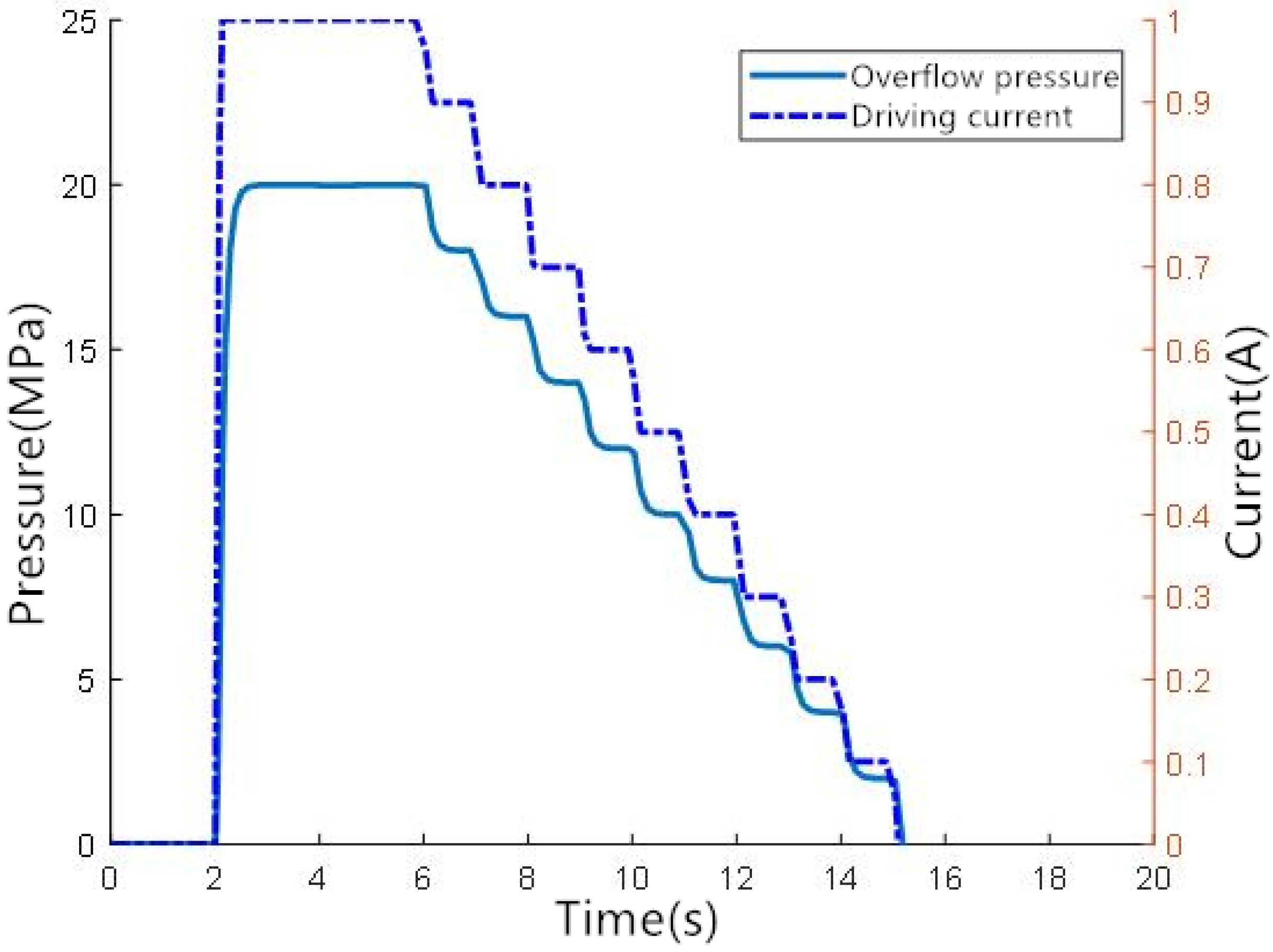
2.2.2. The Pressure Control Algorithm Based on Overflow Characteristics of the Solenoid Valve

The highly automated driving system should have the ability to realize brake-by-wire control even when the regenerative braking system has a single point of failure, which means that the regenerative braking system should have a second component to realize brake-by-wire.
The second braking component in the fully decoupled regenerative braking system is the redundant brake unit (RBU). According to the description of RBU above, the RBU has two pressure regulation valves (PRV), which are linear, normally open solenoid valves. After the coil is energized, the moving iron and the fixed iron of the solenoid valve will generate electromagnetic force due to magnetization. The electromagnetic force pushes the moving iron and the spool to overcome the hydraulic force and spring force, to close the solenoid valve [23]. The spool motion equation of the linear, normally open solenoid valve can be expressed as follows:
m c p v x ¨ c p v = F m p v F h p v F s p v ,
where m c p v is the mass of the moving iron, kg; x ¨ c p v is the displacement of the moving iron, m; F m p v   is the electromagnetic force, N; F h p v   is the hydraulic force, N; and F s p v is the spring force, N.
Among the above three forces, the electromagnetic force is related to the position of the spool and the coil current [24], which can be calculated by Formula (19). The spring force is related to spring stiffness, preload, and displacement, while the hydraulic force is related to spool stress area and hydraulic pressure. These two forces can be calculated by the AMESim simulation model.
F m p v = A p v μ 0 N c 2 i c 2 2 ( x c p v 0 x c p v ) 2 ,
where A p v is the area of working air gap, m2; μ 0 is the vacuum permeability, N/(A2); N c is the coil turn; i c is the coil current, A; and x c p v 0 is the initial working air gap of the spool, m.
As shown in Figure 10, on the basis of the modeling method described in reference [25,26], this paper establishes the simulation model of the normally open linear solenoid valve in AMESim. In the AMESim model, the electromagnetic force and coil inductance of the solenoid valve are obtained by looking up the table. The coil model is represented by an RL series circuit, and the power supply is DC power and is controlled by PWM signals.
For the connection of the hydraulic components, the inlet port of the solenoid valve is connected to a constant pressure source and the outlet port is connected to the brake. By applying different driving currents to the solenoid valve, the pressure response curve can be obtained, as shown in Figure 11. It can be seen that in a certain range of driving current, the linear normally open solenoid valve shows a proportional overflow characteristic, which means the final steady-state overflow pressure can be adjusted by controlling the driving current.
In the redundant brake unit (RBU), the overflow pressure of the pressure regulation valve (PRV) is approximately equal to the wheel cylinder pressure, so the wheel cylinder pressure can be adjusted by controlling the coil current. The relationship between wheel cylinder pressure and coil current can be expressed as follows:
P w c P m c = K P R V i c ,
where K P R V is the proportional coefficient between overflow pressure and coil current, ml/Mpa; P w c is the wheel cylinder pressure, Mpa; and P M c is the master cylinder pressure, Mpa.

3. Results and Discussion

The brushless motor model and pressure control model are built in Matlab/Simulink, and the hydraulic braking system model is built in AMESim. The main parameters used in the simulations are set in Table 1.

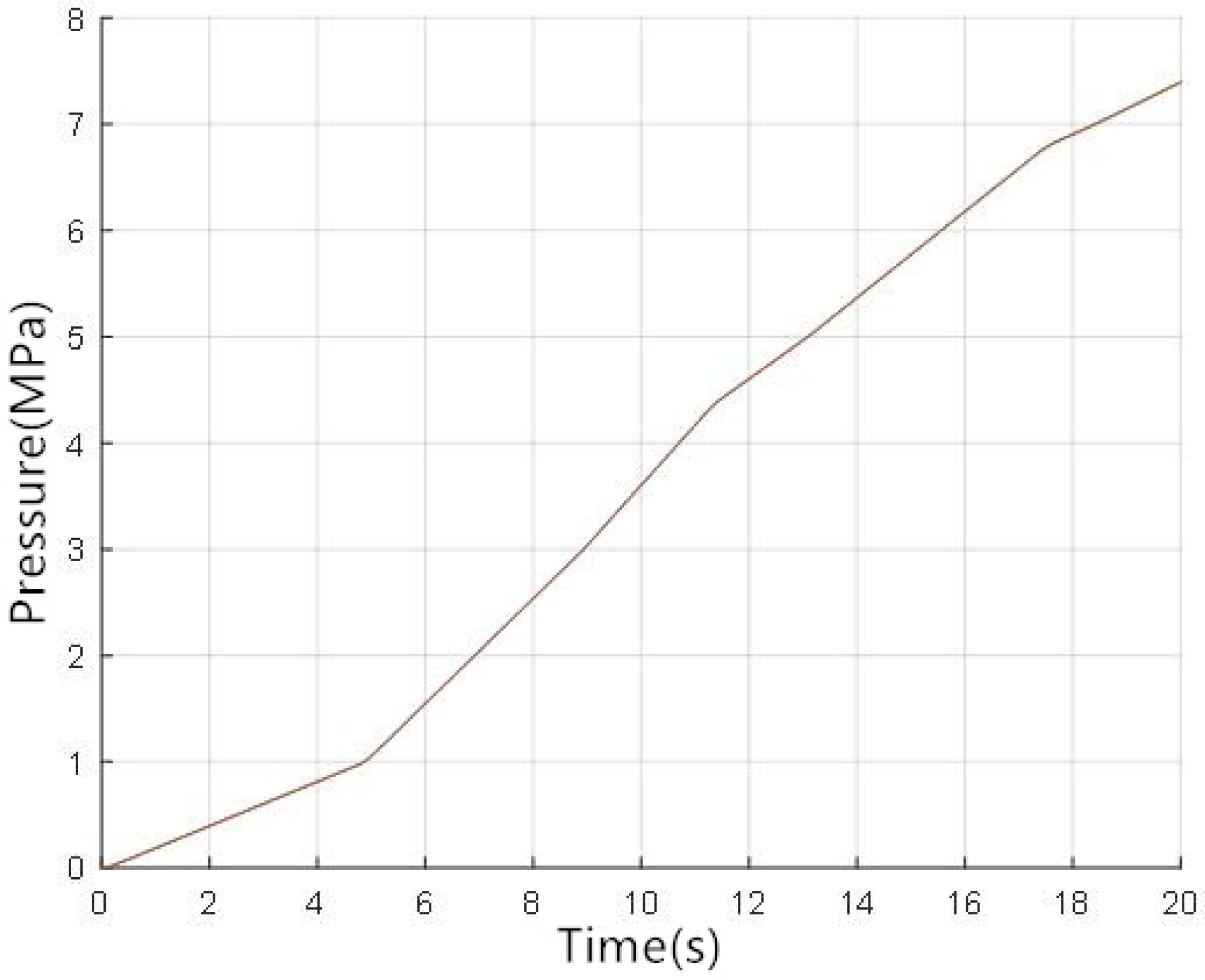
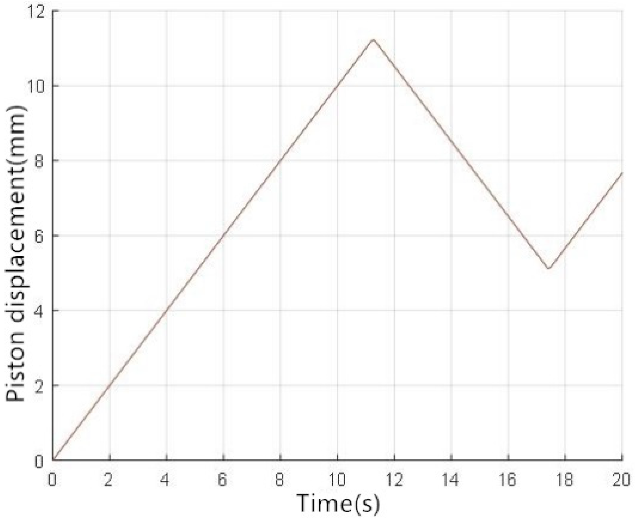
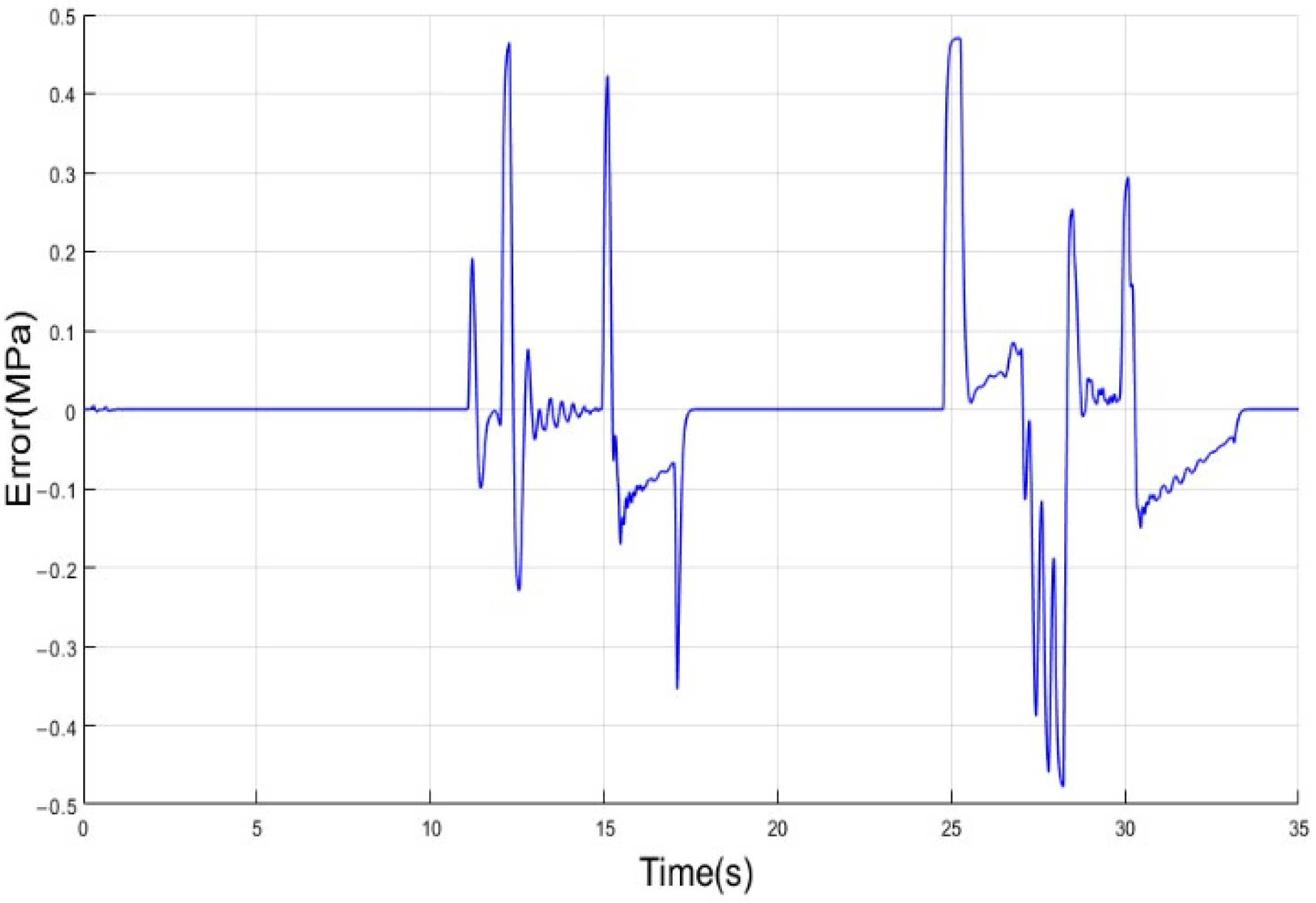
3.1. Results and Discussion of Conventional Braking Mode

In order to verify the pressure regulation performance of the power brake cylinder (PBC), the pressurization test of PBC was carried out. In the pressurization test, the piston of PBC moves at a fixed speed, and the controller of the power brake unit (PBU) switches the pressure regulation mode by adjusting the solenoid valves. After switching the mode, the piston changes the direction of movement, but the speed remains unchanged. The simulation results are shown in Figure 12, Figure 13, Figure 14 and Figure 15.
According to the above simulation results, with the gradual increase of pressure, PBC will switch the pressure regulation mode from low pressure to medium pressure and high pressure, by changing the piston displacement and equivalent cross-sectional area. Although the pressure regulation mode changes, the brake pressure does not change suddenly and keeps at a steady growth. If we look closely at the changing trend of the pressure, we can see that the pressurization rate gradually decreases as the pressure regulation mode switches from low to medium and high pressure. This is because the equivalent piston cross-sectional area in medium and high pressure modes is smaller than that in the low pressure mode. As the PBC piston moves at a fixed speed, the fluid volume discharged from the PBC is smaller too, resulting in a lower pressurization rate.
In addition, although the pressure changes greatly, the absolute value of push rod force changes little. In detail, the absolute value of the push rod force does not increase significantly as the pressure increases. Compared to the medium pressure mode, the push rod force is even reduced in high pressure mode. This is because the high-pressure mode has the smaller equivalent piston cross-sectional area. A benefit from this is that the piston can generate a higher pressure with the same push rod force. As a result, this variable piston cross-sectional area control method can reduce the output torque range of the motor, and reduce the performance requirements of the PBC motor.
In order to verify the pressure control accuracy of the pressure control algorithm based on P-V characteristics, a random pressure following test is carried out. The simulation results are shown in Figure 16 and Figure 17.
From the above simulation results, it can be seen that the proposed pressure control algorithm, based on P-V characteristics, can accurately follow the target pressure, and the control error is within 0.5 MPa, which can meet the safety requirements of the highly automated driving system.

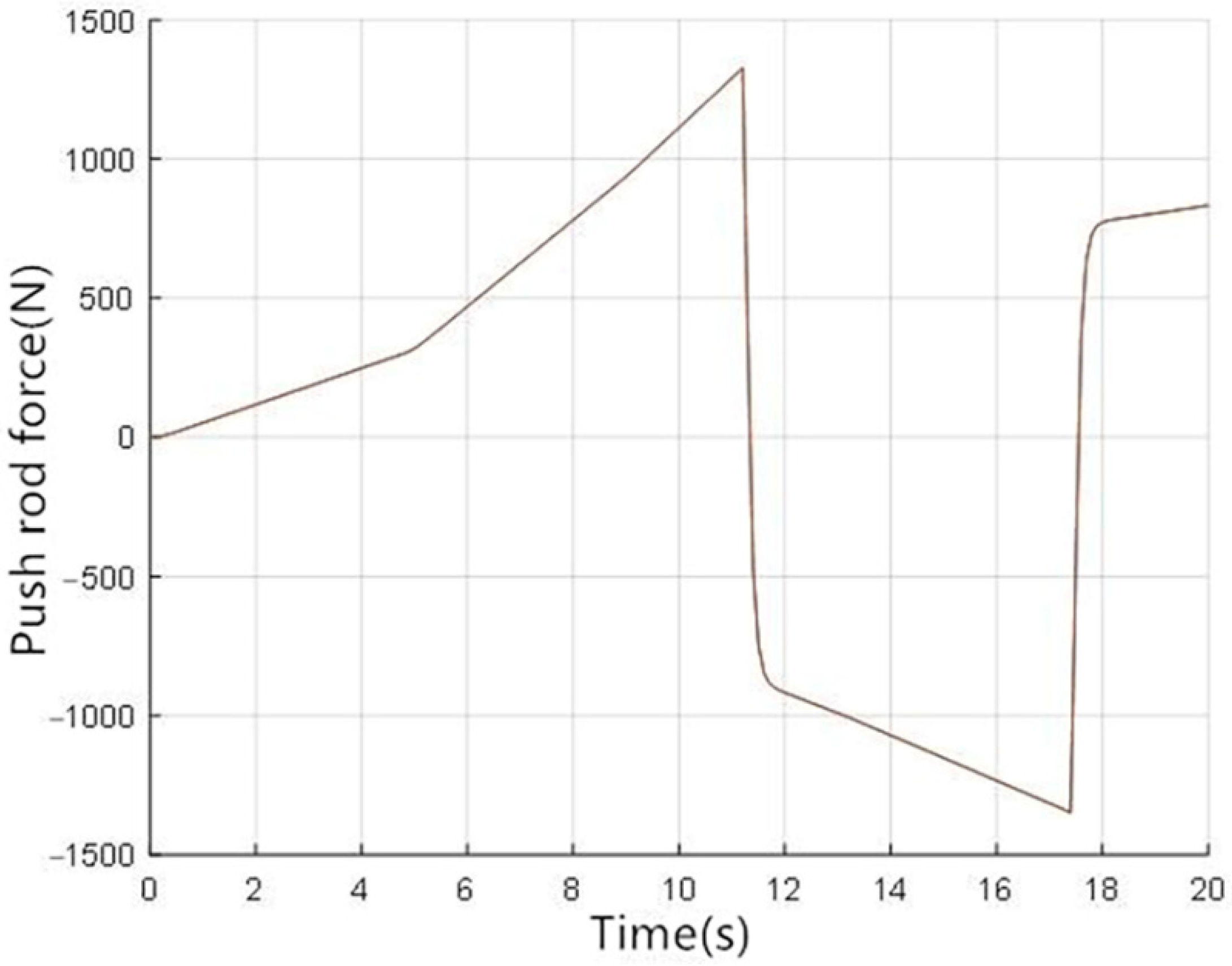
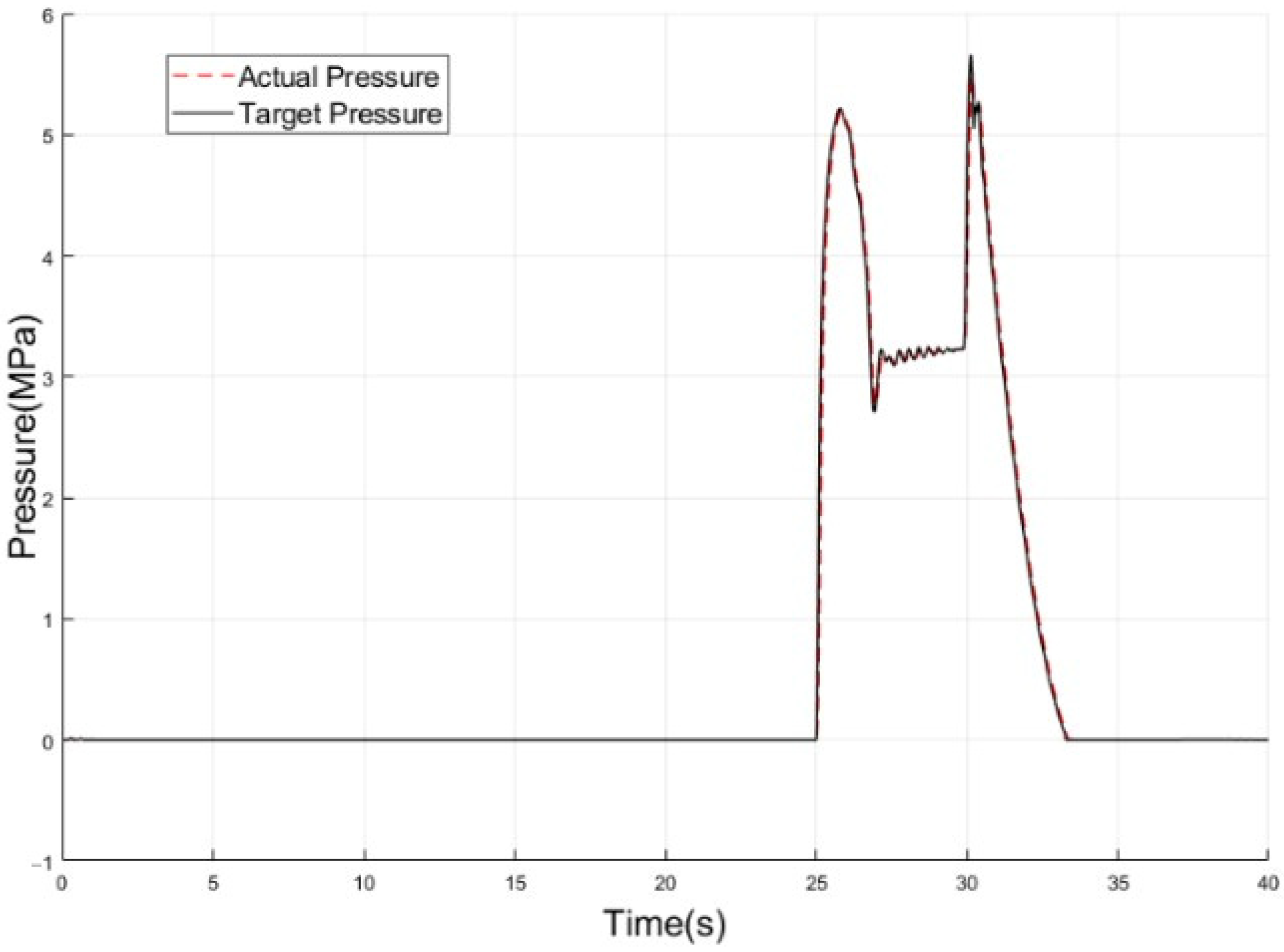
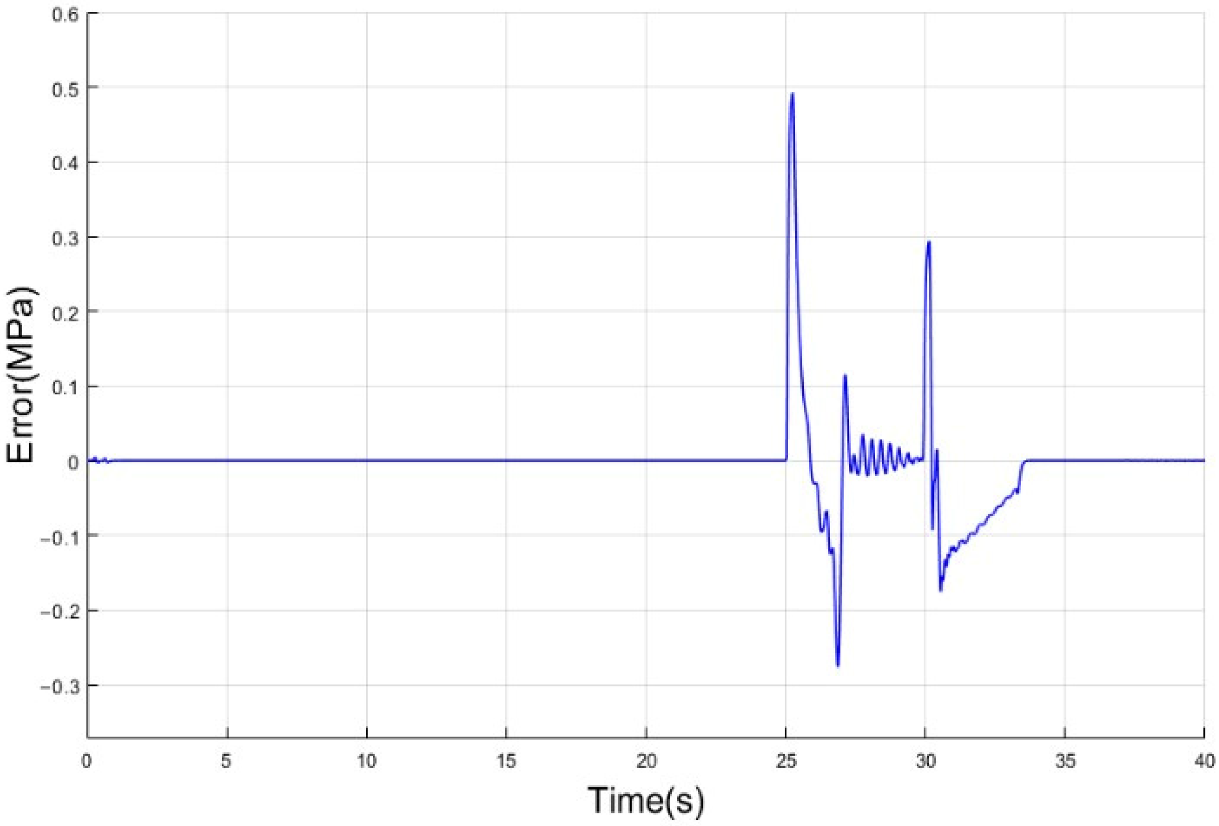
3.2. Results and Discussion of Redundant Braking Mode

In the redundant braking mode, the redundant brake unit (RBU) realizes accurate pressure control by adjusting the coil current of the pressure regulation valve (PRV). In order to verify the control effects of the RBU pressure control algorithm, a random pressure following test is carried out. The simulation results are shown in Figure 18 and Figure 19, and it can be seen that the RBU pressure control algorithm can also accurately follow the target pressure, which means the proposed regenerative braking system can maintain a high braking performance in redundant braking mode. However, this control method requires the hydraulic pump to work frequently, and the noise is large, so it is only applied when the main brake unit (MBU) fails.

4. Conclusions

As the traditional regenerative braking system cannot be applied to highly automated driving vehicles, this paper proposes a fully decoupled regenerative braking system that could meet the functional requirements of highly automated driving vehicles. The proposed regenerative braking system has two working modes: conventional braking and redundant braking. In order to ensure that the regenerative braking system can brake safely in both working modes, this paper proposes the pressure control algorithm, based on P-V characteristics, and the pressure control algorithm, based on the overflow characteristics of solenoid valves. The simulation results show that the proposed regenerative braking system can ensure braking safety under both conventional and redundant braking modes. Meanwhile, the proposed pressure control algorithm can accurately follow the target pressure in both braking modes. The pressure control error is within 0.5 MPa, which can meet the safety requirements of highly automated driving vehicles.
Considering that highly automated driving vehicles have extremely high requirements for system execution efficiency, safety, and reliability, simulation experiments alone are not sufficient to illustrate the feasibility and effectiveness of the proposed regenerative braking system. Therefore, in future work, the prototype of the regenerative braking system will be produced, and the hardware in the loop tests will be conducted.

Author Contributions

Conceptualization, L.C. and D.Z.; methodology, software, validation, Y.X., D.Z. and C.C.; investigation, resources, writing—original draft preparation, writing—review and editing, visualization, supervision, project administration, L.C., Y.X., D.Z. and C.C. All authors have read and agreed to the published version of the manuscript.

Funding

This research was funded by key research and development plan in Tianjin (20YFZCGX00770).

Institutional Review Board Statement

Not applicable.

Informed Consent Statement

Not applicable.

Conflicts of Interest

The authors declare no conflict of interests.

References

  1. Fernandes, P.; Nunes, U. Multiplatooning leaders positioning and cooperative behavior algorithms of communicant automated vehicles for high traffic capacity. IEEE Trans. Intell. Transp. Syst. 2015, 16, 1172–1187. [Google Scholar] [CrossRef] [Green Version]
  2. Han, Y.; Chen, D.; Ahn, S.; Hegyi, A. Analysis of driver response and traffic evolution under variable speed limit control. Transp. Res. Rec. 2015, 2490, 1–10. [Google Scholar] [CrossRef]
  3. Maimaris, A.; Papageorgiou, G. A review of intelligent transportation systems from a communications technology perspective. In Proceedings of the IEEE Conference on Intelligent Transportation Systems, Proceedings, ITSC, Rio de Janeiro, Brazil, 1–4 November 2016; pp. 54–59. [Google Scholar]
  4. Zhang, J.; Wang, F.Y.; Wang, K.; Lin, W.H.; Xu, X.; Chen, C. Data-driven intelligent transportation systems: A survey. IEEE Trans. Intell. Transp. Syst. 2011, 12, 1624–1639. [Google Scholar] [CrossRef]
  5. Sun, C.; Chu, L.; Guo, J.; Shi, D.; Li, T.; Jiang, Y. Research on adaptive cruise control strategy of pure electric vehicle with braking energy recovery. Adv. Mech. Eng. 2017, 9. [Google Scholar] [CrossRef]
  6. Ma, H.; Chu, L.; Guo, J.; Wang, J.; Guo, C. Cooperative Adaptive Cruise Control Strategy Optimization for Electric Vehicles Based on SA-PSO with Model Predictive Control. IEEE Access 2020, 8, 225745–225756. [Google Scholar] [CrossRef]
  7. Yang, D.G.; Jiang, K.; Zhao, D.; Yu, C.L.; Cao, Z.; Xie, S.C.; Xiao, Z.Y.; Jiao, X.Y.; Wang, S.J.; Zhang, K. Intelligent and connected vehicles: Current status and future perspectives. Sci. China Technol. Sci. 2018, 61, 1446–1471. [Google Scholar] [CrossRef]
  8. Meier, J.N.; Kailas, A.; Adla, R.; Bitar, G.; Moradi-Pari, E.; Abuchaar, O.; Ali, M.; Abubakr, M.; Deering, R.; Ibrahim, U.; et al. Implementation and evaluation of cooperative adaptive cruise control functionalities. IET Intell. Transp. Syst. 2018, 12, 1110–1115. [Google Scholar] [CrossRef]
  9. Depner, N.; Graaf, R.; Spahl, R.; Wielgos, S. Vehicle Concept with Electric Wheel Hub Drives. ATZ Worldw. 2016, 118, 42–47. [Google Scholar] [CrossRef]
  10. Conti, R.; Galardi, E.; Meli, E.; Nocciolini, D.; Pugi, L.; Rindi, A. Energy and wear optimisation of train longitudinal dynamics and of traction and braking systems. Veh. Syst. Dyn. 2015, 53, 651–671. [Google Scholar] [CrossRef]
  11. Pugi, L.; Malvezzi, M.; Papini, S.; Vettori, G. Design and preliminary validation of a tool for the simulation of train braking performance Luca Pugi Monica Malvezzi Susanna Papini. J. Mod. Transp. 2013, 21, 247–257. [Google Scholar] [CrossRef] [Green Version]
  12. Ganzel, B.J. Hydraulic Brake System with Controlled Boost. U.S. Patent 8544962, 29 October 2008. [Google Scholar]
  13. Akita, K.; Yamamoto, T.; Miyazaki, T.; Uraoka, T.; Watanabe, K. Brake Control System. U.S. Patent 9238454, 4 February 2011. [Google Scholar]
  14. Kunz, A.; Kunz, M.; Vollert, H.; Förster, M. Electromechanical Brake Booster for all Drive Concepts and Automated Driving. ATZ Worldw. 2018, 120, 58–61. [Google Scholar] [CrossRef]
  15. Matsushita, S. Vehicle Braking Device. U.S. Patent 8746813, 6 May 2010. [Google Scholar]
  16. Ohkubo, N.; Matsushita, S.; Ueno, M.; Akamine, K.; Hatano, K. Application of electric servo brake system to plug-in hybrid vehicle. SAE Int. J. Passeng. Cars Electron. Electr. Syst. 2013, 6, 255–260. [Google Scholar] [CrossRef]
  17. Xiong, Z.; Guo, X.; Yang, B.; Pei, X.; Zhang, J. Modeling and pressure tracking control of a novel electro-hydraulic braking system. Adv. Mech. Eng. 2018, 10. [Google Scholar] [CrossRef]
  18. Continental Mk C1. Available online: https://www.continental-automotive.com/en-gl/Passenger-Cars/Safety/Products/Brakes/Electronic-Brakes/MK-C1 (accessed on 3 March 2020).
  19. Zhao, D.; Chu, L.; Xu, N.; Sun, C.; Xu, Y. Development of a cooperative braking system for front-wheel drive electric vehicles. Energies 2018, 11, 378. [Google Scholar] [CrossRef] [Green Version]
  20. Lv, C.; Zhang, J.; Li, Y. Extended-Kalman-filter-based regenerative and friction blended braking control for electric vehicle equipped with axle motor considering damping and elastic properties of electric powertrain. Veh. Syst. Dyn. 2014, 52, 1372–1388. [Google Scholar] [CrossRef]
  21. Lee, C.H.; Lee, J.M.; Choi, M.S.; Kim, C.K.; Koh, E.B. Development of a semi-empirical program for predicting the braking performance of a passenger vehicle. Int. J. Automot. Technol. 2011, 12, 193–198. [Google Scholar] [CrossRef]
  22. Vasilevsky, M.; Razva, A.; Grebenkov, Y. Determination of tension of friction of piston of dispersible material is in a pipeline. In Proceedings of the MATEC Web of Conferences, Tomsk, Russian Federation, 22–23 April 2015. [Google Scholar]
  23. Zhang, J.; Lv, C.; Yue, X.; Li, Y.; Yuan, Y. Study on a linear relationship between limited pressure difference and coil current of on/off valve and its influential factors. ISA Trans. 2014, 53, 150–161. [Google Scholar] [CrossRef] [PubMed]
  24. Kim, Y.S. Electromagnetic force calculation method in finite element analysis for programmers. Univers. J. Electr. Electron. Eng. 2019, 6, 62–67. [Google Scholar] [CrossRef]
  25. Chu, L.; Zhao, D.; Li, W. Modeling and dynamic characteristics simulation for fast-switching solenoid valves in electro-hydraulic braking systems. Qiche Gongcheng/Automot. Eng. 2017, 39, 61–65. [Google Scholar] [CrossRef]
  26. Tomasikova, M.; Tropp, M.; Gajdosik, T.; Krzywonos, L.; Brumercik, F. Analysis of Transport Mechatronic System Properties. In Proceedings of the Procedia Engineering, High Tatras Grand Hotel Bellevue, Vysoké Tatry Slovakia, 31 May 2017; pp. 881–886. [Google Scholar]
Figure 1. Structure of the hydraulic braking system. MBU—main brake unit; RBU—redundant brake unit; PSU—pedal simulation unit; PBU—power brake unit; MHCU—main hydraulic control unit; PSS—pedal stroke simulator; MC—master cylinder; SCV—simulator cut-off valve; PBCV—power brake cylinder cut-off valve; PBC—power brake cylinder; MSV—mode switching valve; PBIV—power brake cylinder isolation valve; MCIV—master cylinder isolation valve; HCV—hydraulic connecting valve; FLIV—inlet valve of left-front wheel cylinder; FLOV—outlet valve of left-front wheel cylinder; RRIV—inlet valve of right-rear wheel cylinder; RROV—outlet valve of right-rear wheel cylinder; FRIV—inlet valve of right-front wheel cylinder; FROV—outlet valve of right-front wheel cylinder; RLIV—inlet valve of left-rear wheel cylinder; RLOV—outlet valve of left-rear wheel cylinder; HSV—high-pressure switching valve; PRV—pressure regulation valve.
Wevj 12 00112 g001
Figure 2. Structure of the power brake cylinder (excluding motor and transmission mechanism).
Wevj 12 00112 g002
Figure 3. The flow direction of brake fluid and the action of solenoid valves under low pressure mode.
Wevj 12 00112 g003
Figure 4. The flow direction of brake fluid and the action of solenoid valves under medium pressure mode.
Wevj 12 00112 g004
Figure 5. The flow direction of brake fluid and the action of solenoid valves under high pressure mode.
Wevj 12 00112 g005
Figure 6. Working state of RBU during active pressurization.
Wevj 12 00112 g006
Figure 7. Schematic representation of the pressure control algorithm.
Wevj 12 00112 g007
Figure 8. P-V characteristic of front wheel brake.
Wevj 12 00112 g008
Figure 9. P-V characteristic of rear wheel brake.
Wevj 12 00112 g009
Figure 10. The AMESim model of the solenoid valve.
Wevj 12 00112 g010
Figure 11. The overflow characteristic curve of the solenoid valve.
Wevj 12 00112 g011
Figure 12. Pressure curve of PBC.
Wevj 12 00112 g012
Figure 13. Piston displacement curve of PBC.
Wevj 12 00112 g013
Figure 14. Push rod force curve of PBC.
Wevj 12 00112 g014
Figure 15. Pressure regulation mode curve of PBC.
Wevj 12 00112 g015
Figure 16. Pressure control effects.
Wevj 12 00112 g016
Figure 17. Pressure control error.
Wevj 12 00112 g017
Figure 18. Pressure control effects.
Wevj 12 00112 g018
Figure 19. Pressure control error.
Wevj 12 00112 g019
Table 1. Main parameters used in the simulations.
ParameterValueUnits
Cross-sectional area of PBC piston329mm2
Cross-sectional area of PBC piston rod119mm2
Diameter of front wheel cylinder57.15mm
Diameter of rear wheel cylinder37.68mm
Diameter of master cylinder20.5mm
Peak power of PBC motor450W
Peak torque of PBC motor2.2N · m
Rated speed of PBC motor4000r/min
Flexibility of the brake hose6.25 × 10−3ml/MPa
Ball screw lead0.005m
Transmission ratio of the first stage gear1.8/
Ball screw efficiency0.96/
Proportional coefficient of PRV19.8MPa/A
Diameter of PSS15mm
Stiffness of PSS spring(1st stage)9.03N/mm
Stiffness of PSS spring(2nd stage)42.16N/mm
Publisher’s Note: MDPI stays neutral with regard to jurisdictional claims in published maps and institutional affiliations.

