1. Introduction
Due to increasing demand for vehicles with lower consumption and emissions, the electric vehicle is one of the alternatives for efficient and clean energy solution [
1,
2]. The concentrations of PM
10, PM
2.5, O
3, and N
2O in Bangkok, Thailand still exceed the standard level of national ambient air quality in 2019. This information demonstrates that the Bangkok area is still facing an air pollution problem, with a major contributing factor being transport activity, especially by hazardous particulate matter (PM 2.5) from diesel vehicles’ exhaust emissions. The Pollution Control Department has created a master plan for the Air Quality Management for a 20-year period (2018–2037) including an impact prevention and proactive prevention, which aim to reduce pollution by elevating the standards of exhaust for new vehicles, together with an improvement in fuel quality. This has led to a launch of “zero emission” regulations for new vehicles to promote the usage of electric vehicles and public transportation [
3]. The electrification of public transport vehicles could be carried out by utilizing different technological solutions [
4,
5,
6]. Many challenges facing electric vehicles such as limited range and speed, sparse of electric charging stations, long recharge time, etc. are related to an energy storage system design (energy and power), i.e., battery packs, for any specific application [
6,
7]. Several design approaches on battery sizing have been based on a real-world driving pattern [
5,
8]. Driving cycle is the series of data representing the speed of the vehicle versus time. It is important for a fleet to match routes to battery technology to achieve maximum benefit. Hence, knowledge of driving cycles is important for improving the electric vehicle performance and design purposes [
7,
8,
9].
Driving cycles have been developed by various organizations from many countries. They are used mainly for evaluation of performance, vehicle efficiency, energy consumption, and emission. The patterns and behaviors of driving characteristics differ depending on the area or city and country. It is therefore difficult to use one of the developed driving cycles for another city, even in the same country. As a result, this study focused on developing three different driving cycles of closed-area, inter-city, and local feeder by the collection of real-world data in specific areas. Designing driving cycles is the abstraction and sublimation of a large amount of driving data. Although there are many methods for designing driving cycles, the cognition about its essential characteristic is not very clear [
10]. Many studies around the world [
11,
12] suggested that the driving cycle could be used for estimating the emission and analyzing fuel consumption for vehicles. A study by [
8] also mentioned that pollutant emission and energy economy depend on vehicle characteristics, and actual driving data. In China, energy management strategies (EMS) for a plug-in hybrid electric vehicle (PHEV) were optimized by the driving cycle model and dynamic programming (DP) algorithm [
13]. The relationships between the energy consumption and vehicle velocity, acceleration, and roadway gradient were analysed [
2,
14]. Energy consumption, vehicle scheduling, grid load profiles, and battery capacity were analysed by using an existing bus network in the German city of Muenster regarding its electrification potential with fast charging battery buses [
15]. A practical methodology for constructing a representative driving cycle must reflect the real-world driving conditions; however, there are several methodologies of driving cycle construction depending on the purpose of applying and the organization. The real driving data is thus necessary to estimate the energy consumption for the best electric vehicle efficiency. Several design approaches on battery sizing have been based on a real-world driving pattern [
16]. Sizing battery methodology is based on the power requirements, including sustained speed tests and stochastic driving cycles.
The relationships between different driving patterns and corresponding energy consumptions were investigated in this paper. The main focus was on the comparison of minimum required battery sizing for each type of service route in the vicinity of Bangkok, Thailand. The aim was to provide a qualitative guideline for any interest party/stake-holder about the minimum amount/size of energy storage system needed for the service vehicles which would normally be required to operate in different types of routes for efficient fleet management and planning including relevant charging facilities. This study presented the resulting route specific power and energy consumption analysis for the sizing battery of closed-area, inter-city, and local feeder based on university bus driving cycles in Thailand. First, the driving data of university campus trams, university shuttle bus and university bus (Salaya Link) were collected and used as a reference. Then, the real driving cycle data, i.e., velocity and vehicle global position latitude and longitude, including road slope, were collected through a GPS-based equipment, VBOX VB20SL3, Racelogic Ltd. (Buckingham, UK). Next, the calculated power and energy consumptions were determined and used to design the suitable battery technologies and sizes.
2. Materials and Methods
2.1. Data Collection
The analysis was based on a real-world operating data collected through a GPS-based equipment, VBOX (VB20SL3, Racelogic Ltd.). The details of data collection setup are shown in
Table 1.
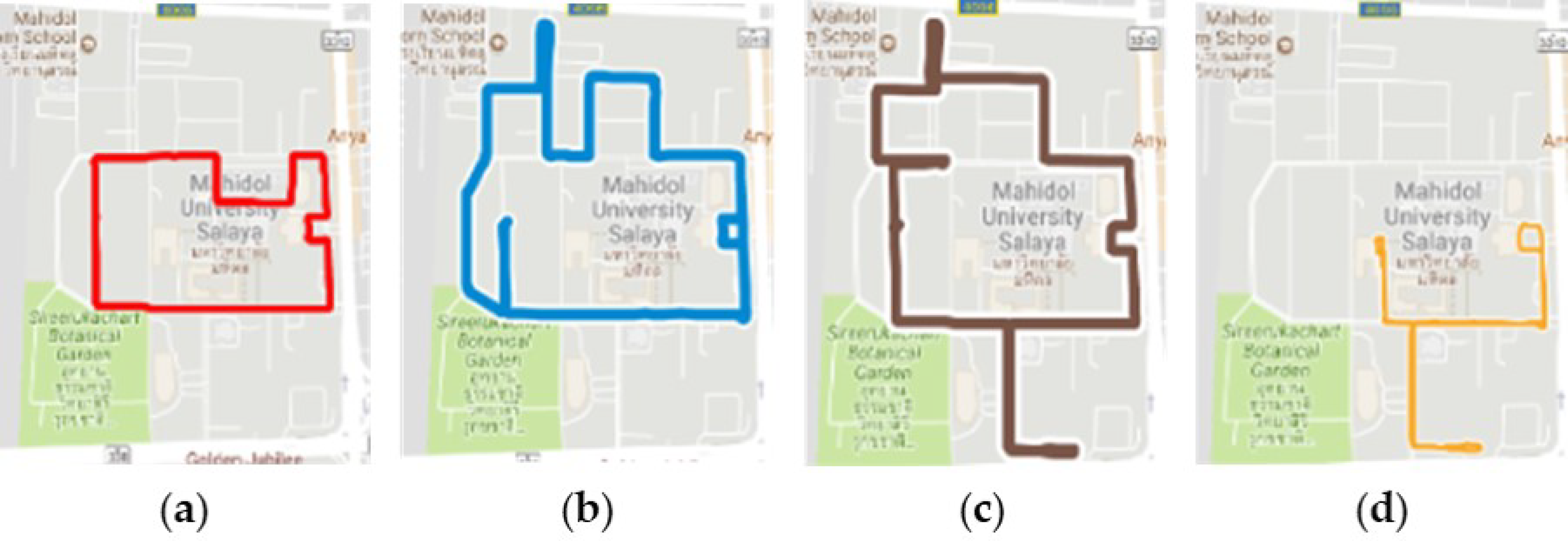
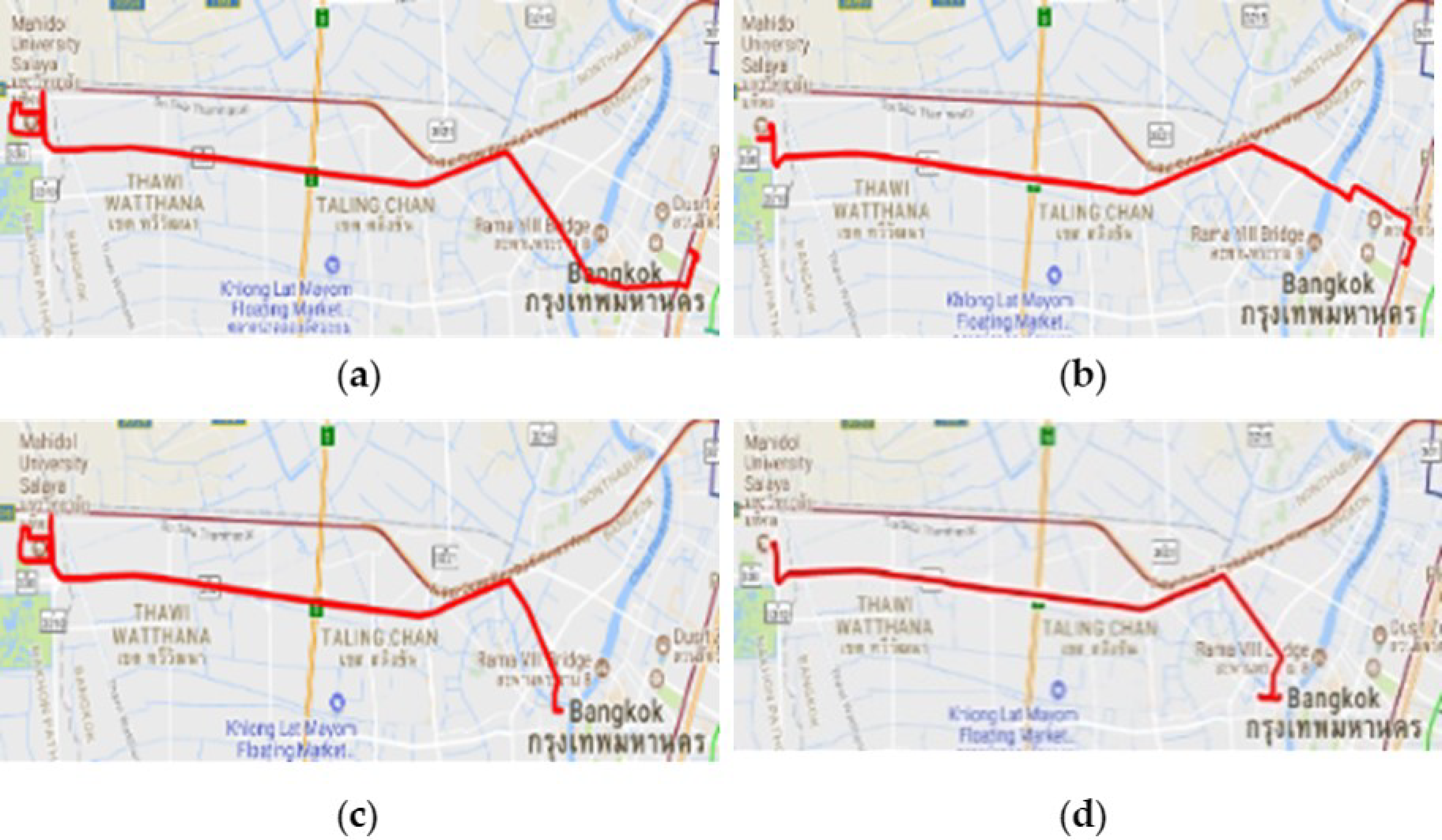
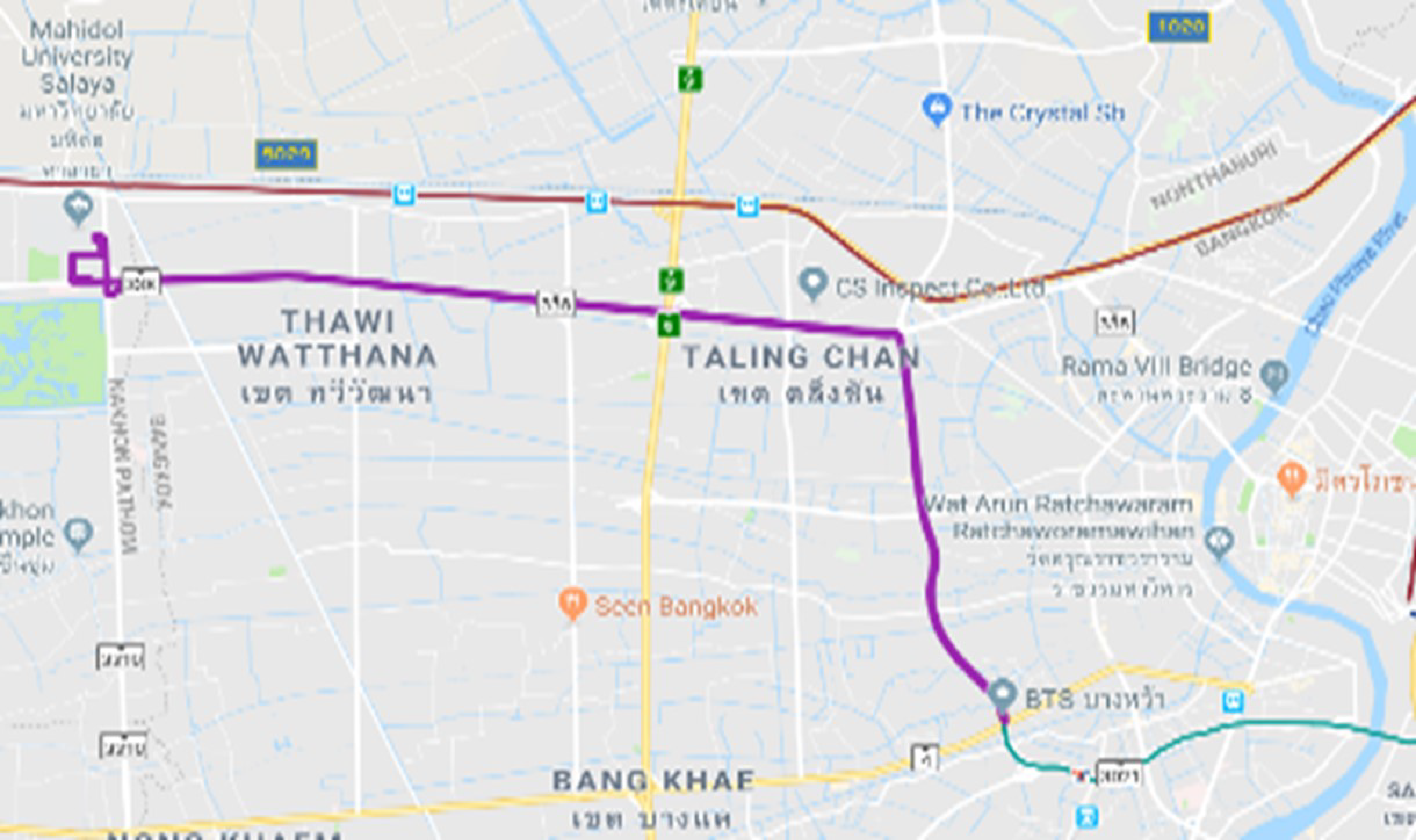
The routes surveyed in this study can be separated into three main types. One of the selected service routes operated only in the university or “closed-area”. Additionally, another service offered transportation between the main and the branch campus located in the city or “inter-city”. The third group of services connected the main campus to the nearest main Mass Transit System or “local feeder”. The operation routes are depicted in
Figure 1,
Figure 2 and
Figure 3.
2.2. Driving Cycle Development
In this study, the relation of driving cycle and energy consumption was a subject of interest for designing energy storage. First, the driving data of tram, shuttle bus, and Salaya Link were collected for closed-area route, inter-city route, and local feeder routes. Collected data were simulated in order to generate the driving cycle pattern.
2.2.1. Collected Driving Data Characteristics
In order to distinguish between each service route, the operating characteristics of each route type were represented by the value of average velocity standard deviation (
Vsd), average speed (
Vavg), maximum velocity (
Vmax), and average time per one cycle. The operating characteristics from closed-area, inter-city, and local feeder of different service routes are shown in
Table 2,
Table 3 and
Table 4.
Tlimit is the averaged time per cycle (s) that is an important factor for driving cycle generation process.
2.2.2. Microtrip Data Segmentation
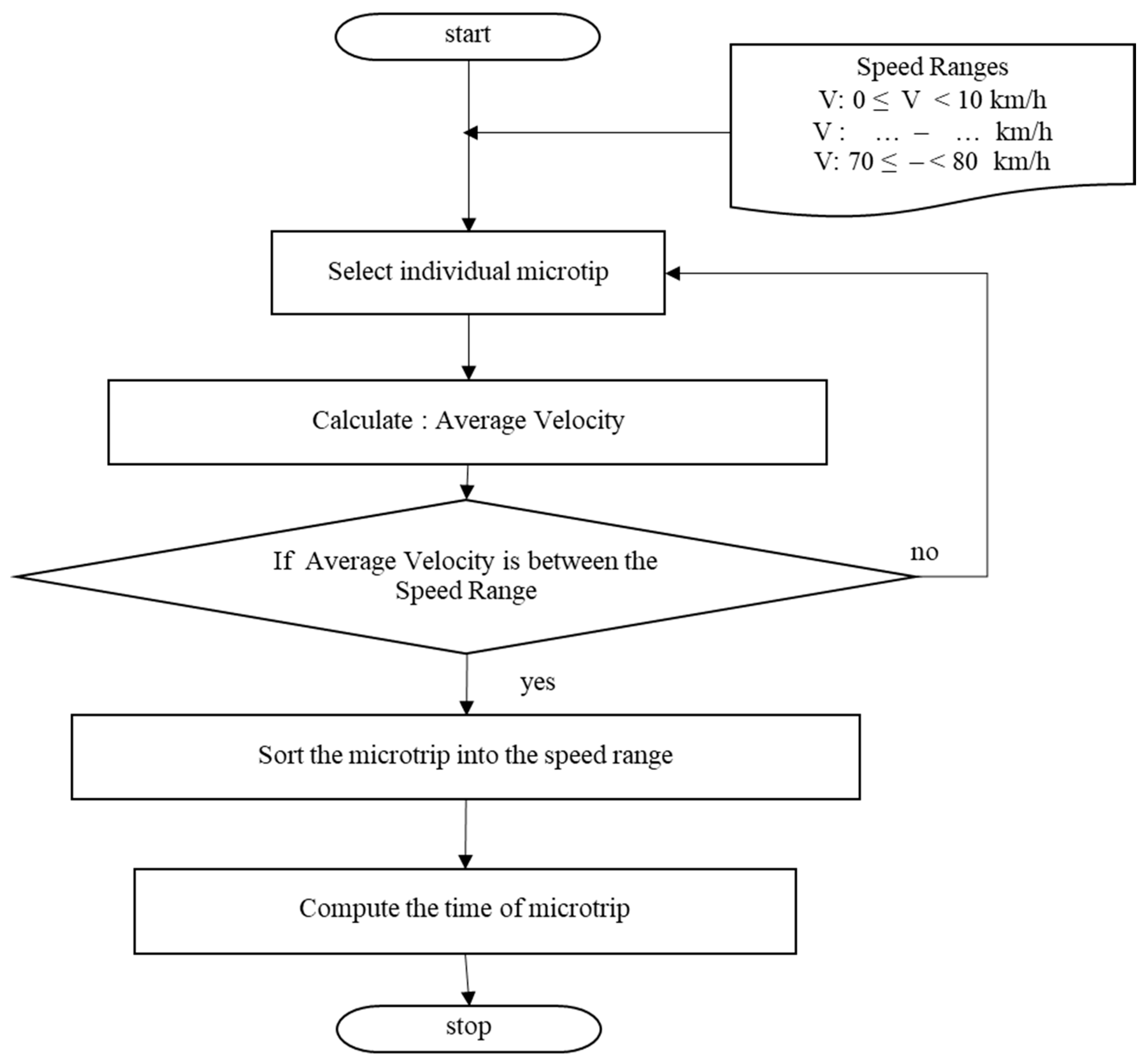
Microtrip is a small portion of driving data that could be separated by periods of idle time. The process details for the driving data separation into microtrips can be illustrated as in
Figure 4. From the previous study [
11], the number of microtrips method (NM) was employed to separate driving data to microtrips. However, it was found that the percentage error of distance and idle time from the NM method was not suitable for a speed range that exceeded 30 km/h. To solve this particular problem, the time spent method (TM) was introduced for improving the obtained distance and idle errors. The speed range limit time
of TM was calculated as Equation (1):
where
is speed range limit time (s),
is time spent in microtrip in each speed ranges (%), and
is the averaged time per cycle (s).
2.2.3. Driving Cycle Construction
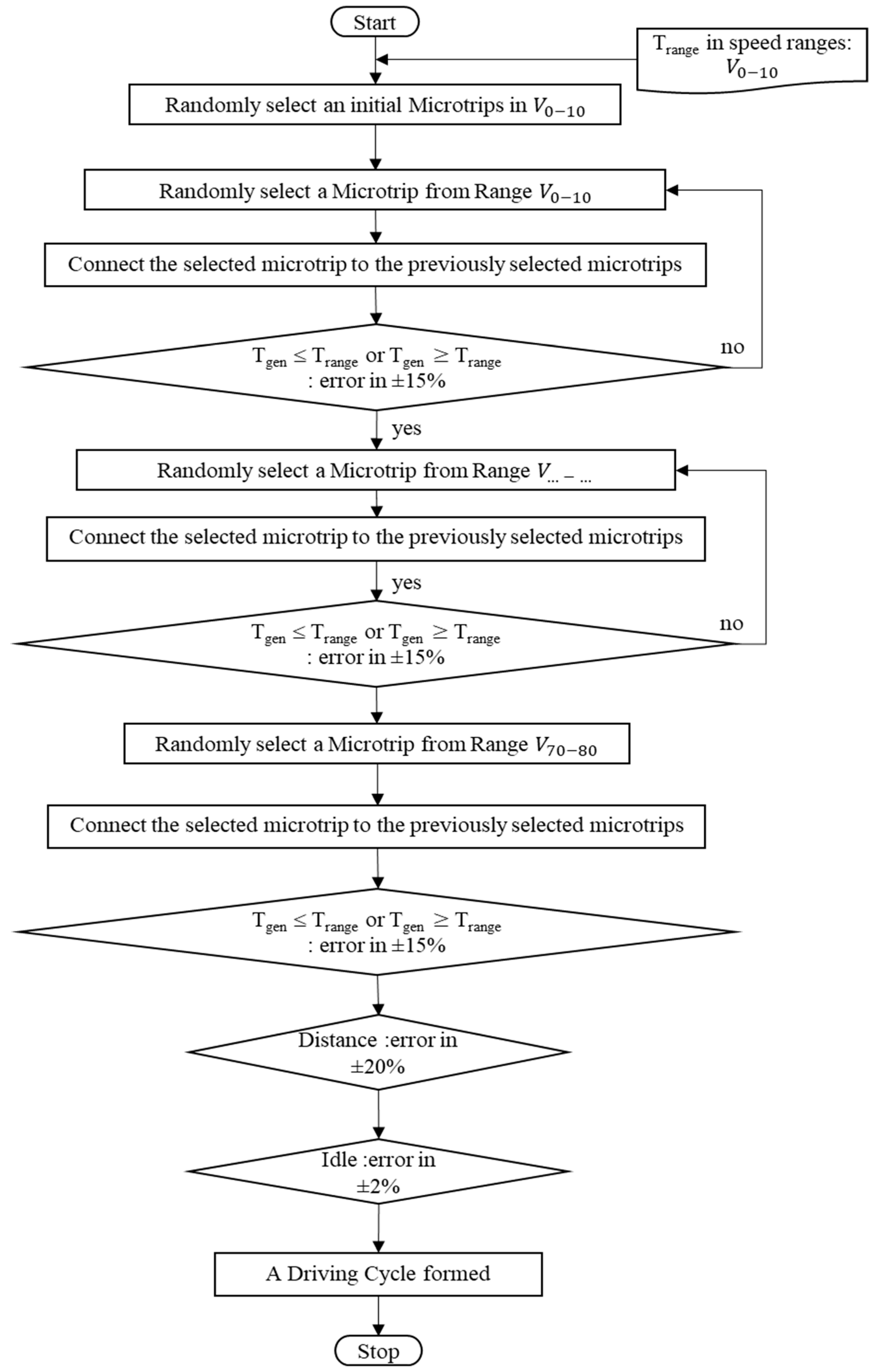
Each route surveyed in this study had a different operating pattern because of the nature of their operations such as T-junction, washboard road, pedestrian crossing, traffic light, etc. In this study, driving cycle patterns were constructed by using the speed range limit time (
) calculated as Equation (1). The sum of error including weight factor use for the main criterion constructed driving cycle must be within 15%. The procedure of driving cycle construction is shown graphically in
Figure 5.
2.2.4. Generated Driving Cycle
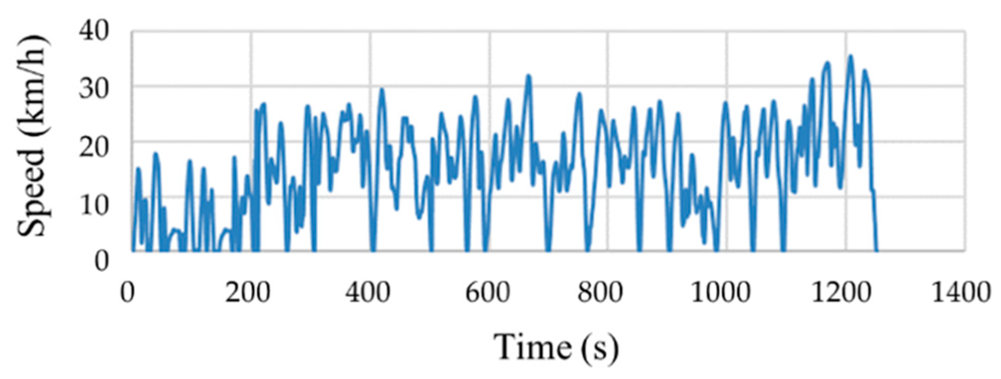
In the previous section, a driving cycle in each service route was formed by a random selection of microtrips from all collected driving data. The example of generated driving cycle is illustrated in
Figure 6. In this study, ten candidates of such driving cycles were generated for each route. The percentage of the error between, time, distance, and idle were considered in order to select the best representative driving cycle. The sum error of the time of generated driving cycle can accepted in 15%.
The generated driving cycle was employed to calculate the errors between generated time of each speed range (
) and
. The resulting error from each speed range, i.e.,
E1,
E2, …,
E8, was the function of discrepancy between
and
including weight factor by time spent of microtrip for each speed range presented in the database. The equation of the errors calculation in each speed range is given by:
where
is the error of the speed range
n-th,
n = 1, 2, …, 8,
is weight factor for each speed range 0–10 km/h, …, and 70–80 km/h, respectively. In other words, the contributions to the total error (
E) were due to the percentage of number of microtrip in each speed range for each route. Finally, the sum of error including weight factor was determined as follows:
where E is the total of error (%).
2.3. Energy Consumption Calculation
2.3.1. Traction Energy Consumption Calculation
The traction energy consumption was calculated from the fundamental theory of vehicle dynamics. In this study, the electric power was assumed to be equal to the power to produce a tractive force and the energy involving the main component and auxiliary system, and regenerative brake were ignored. The tractive force is described by the following equation:
where
is tractive force (N),
is the aerodynamic resistance (N),
is the rolling resistance (N), and
is grade resistance (N).
,
, and
were calculated when a tram was traveling at constant velocity:
where
is velocity (m/s
2),
is coefficient of drag,
is air density (kg/m
3),
is frontal area of the vehicle (m
3),
is rolling resistance constant,
is gravity acceleration (g = 9.81 m/s
2),
is a mass of vehicle (kg),
is the road grade (degree), and
is the Tractive force (N). Finally, the tractive force (
) is found in Equation (8) by combining Equation (5), Equation (6), and Equation (7). To calculate energy consumption, the power for vehicle traveling at velocity (
v) was required. Required power could be determined from the relationship between F and v in Equation (9):
where
power (Watt) is,
is the tractive force (N), and
is velocity (m/s
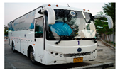
2). In this study, the traction energy consumption was calculated by using geometric parameters of 9-meter EV bus prototype and other constants as shown in
Table 5.
The values from
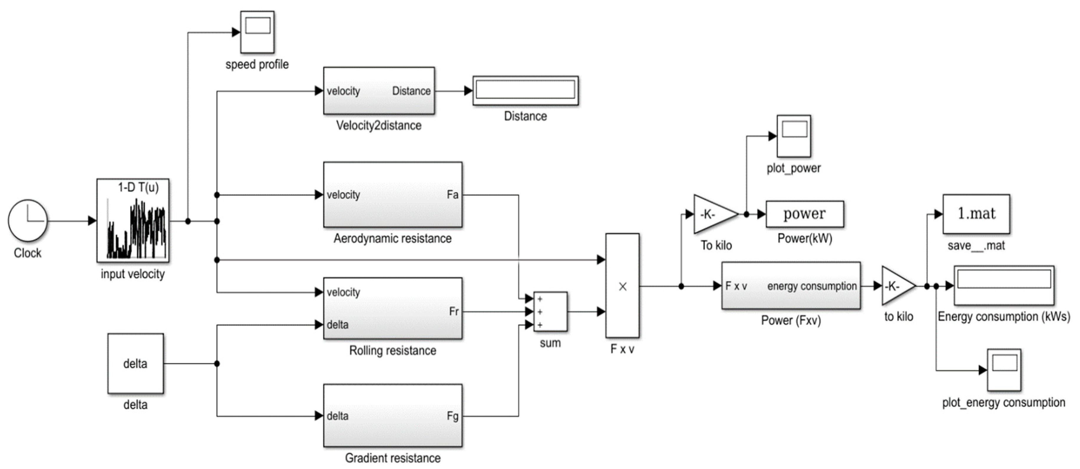
Table 5 were used for calculating power in Equation (9). The transmission efficiency of the electric drivetrain was assumed to be 100% in this study. The control variables were velocity. The closed-area, inter-city, and local feeder routes driving cycles generated as described in the previous section were used as a calculation input for each service route. A vehicle weight was a sum of the curb weight and the maximum passenger weight recorded in each university service routes. MATLAB Simulink (version, Manufacturer, City, US State abbrev. if applicable, Country) was used to calculate the maximum power and the traction energy consumption by using the workflow as depicted in
Figure 7.
2.3.2. EV Main Components and Auxiliary System Energy Consumption Calculation
The main components and auxiliary system could have a significant effect to the overall energy consumption of electric vehicles.
Table 6 shows the parameters of components and auxiliary system for energy consumption calculation.
The constant value of total load for main components and auxiliary system used in this study was 14.26 kW. The EV main component and auxiliary system energy consumption (
) were calculated as Equation (10):
where
is energy consumption of EV main components and auxiliary system (kWh),
is EV main components and auxiliary system load (kW), and
is time of representative driving cycle (s).
2.3.3. Total Energy Consumption
The total energy consumption rate (
) is sum of traction energy consumption (
and main EV components and auxiliary system
divided by distance per cycle of each route. The energy consumption rate (kWh/km) is shown in Equation (11):
where
is energy consumption rate based on driving cycle and EV main components and auxiliary system (kWh/km),
is energy consumption based on driving cycle (kWh),
is energy consumption of EV main components and auxiliary system (kWh), and
is representative driving cycle distance (km).
2.4. Battery Sizing
One significant parameter of electric vehicles is installed battery energy in watt-hours (Wh) because of its high installation cost and lower energy density compared to gasoline. The traction energy consumption rate and minimal required power that were obtained in the previous section were used as the main parameters to design the battery. The minimal required size of the battery is based on daily power usage, charging strategy and feeder design. Operation distance per day (
) of the time spent method was calculated as Equation (12):
where
is operation distance per day (km),
is number of driving cycle per day (cycles), and
is average distance per cycle (km).
For sizing the battery, assuming daily charge, total energy consumption rate (
) and operation distance per day (
) were used to calculate minimal required energy from battery sizing per day of each route as Equation (13):
where
is energy consumption for battery sizing (kWh),
is sum of traction energy consumption rate and EV main components and auxiliary system (kWh/km), and
is operation distance per day (km).
3. Results and Discussion
3.1. Driving Cycle
The time spent for the microtrip in each speed range (
) was used to generate the driving cycle which is the sum of time error (
E) of each speed range that must be within 15% as explained in
Section 2.2. Close-area, inter-city, and local feeder had significantly different characteristics, close-area speed range was 0–40 km/h and inter-city and local feeder speed range was 0–100 km/h. The resulting driving cycles were then constructed as explained in
Section 2.2.3. Ten candidates of generated driving cycle were chosen by the lowest sum of error which had taken into account the weight factor as explained in
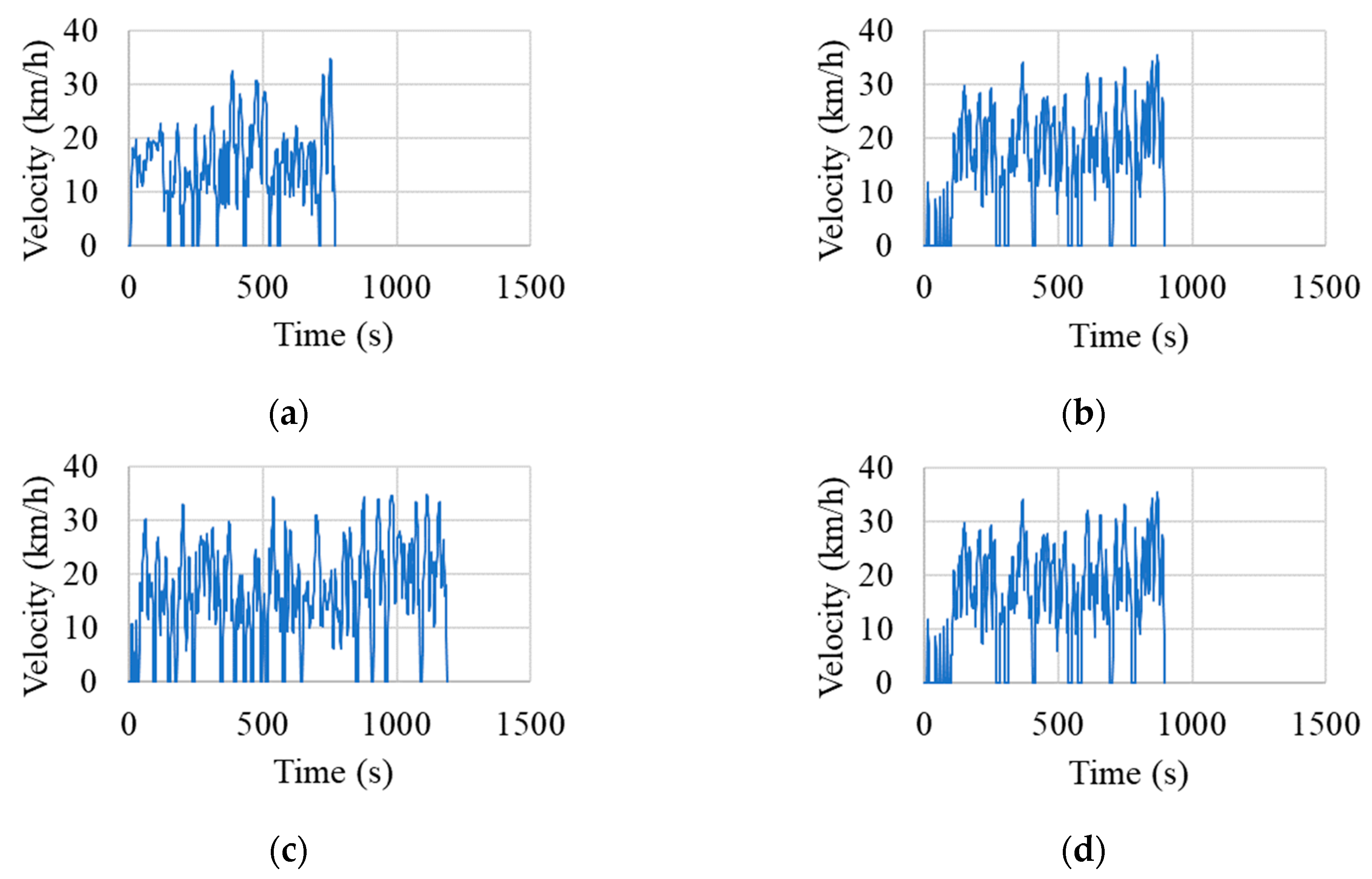
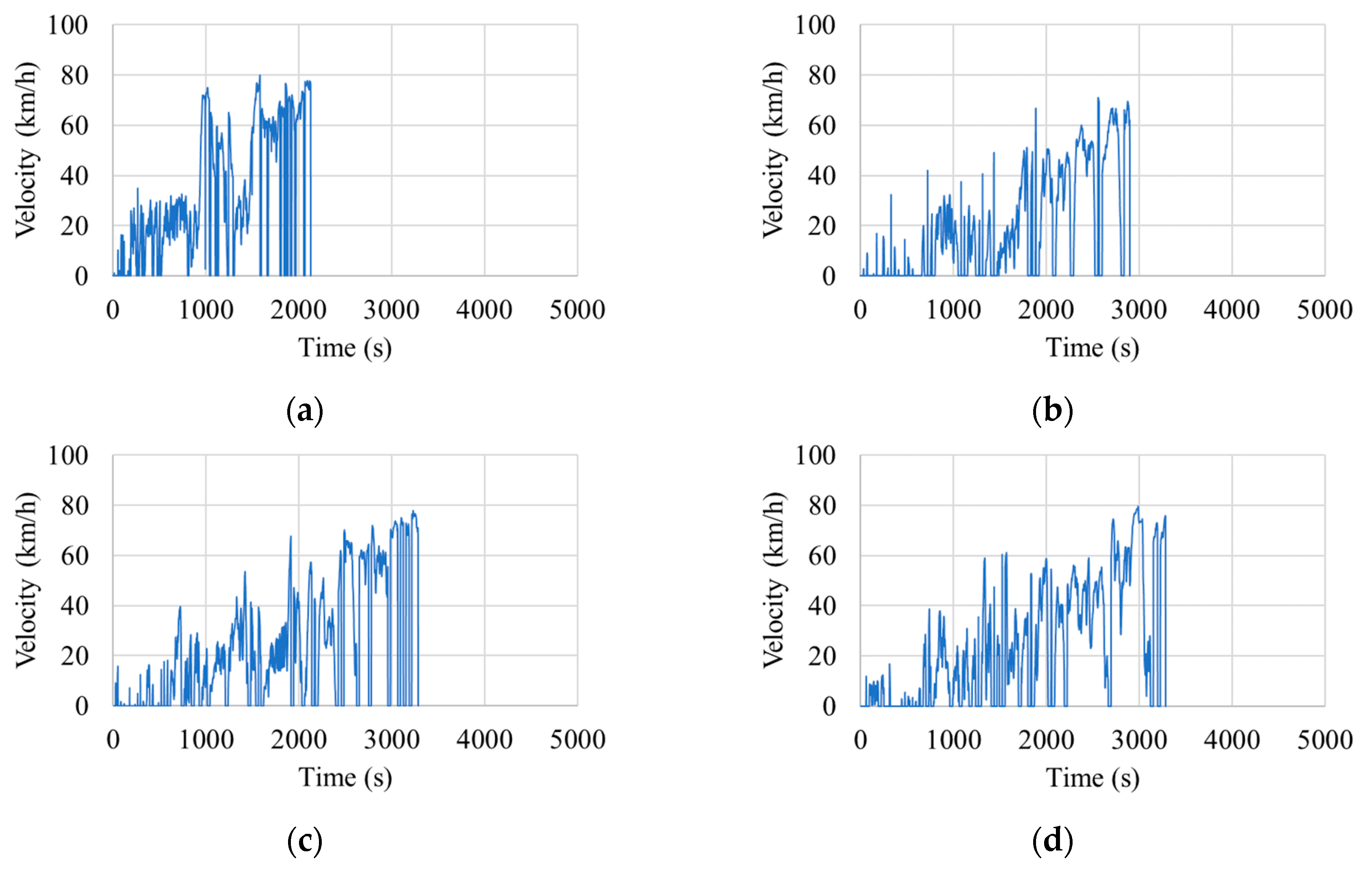
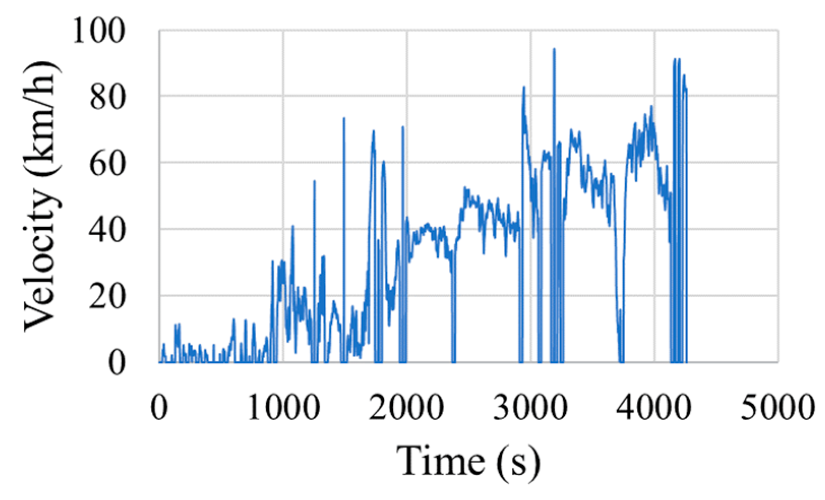
Section 2.2.4. The representative driving cycles for each route are shown in
Figure 8,
Figure 9 and
Figure 10.
The maximum errors for time, distance, and idle obtained values of sum of error (E) from number of microtrips method (NM) of closed-area operated by tram were 6.62%, 11.52%, and 6.06%, respectively. Meanwhile, the maximum errors of time, distance, and idle for inter-city routes operated by shuttle bus were 8.16%, 32.76%, and 79.68%, respectively. This was believed to be due to the presence of long-length microtrips when vehicle speed exceeded 30 km/hr, and the insufficient amount of microtrip percentage in NM method leading to difficultiesin generating a driving cycle. Therefore, with these errors, it could be said that NM methods were not appropriated for generating driving cycles representing the routes of interest in this study. Therefore, the time spent method (TM) was introduced for solving the problem of distance and idle errors with the speed range higher than 30 km/h.
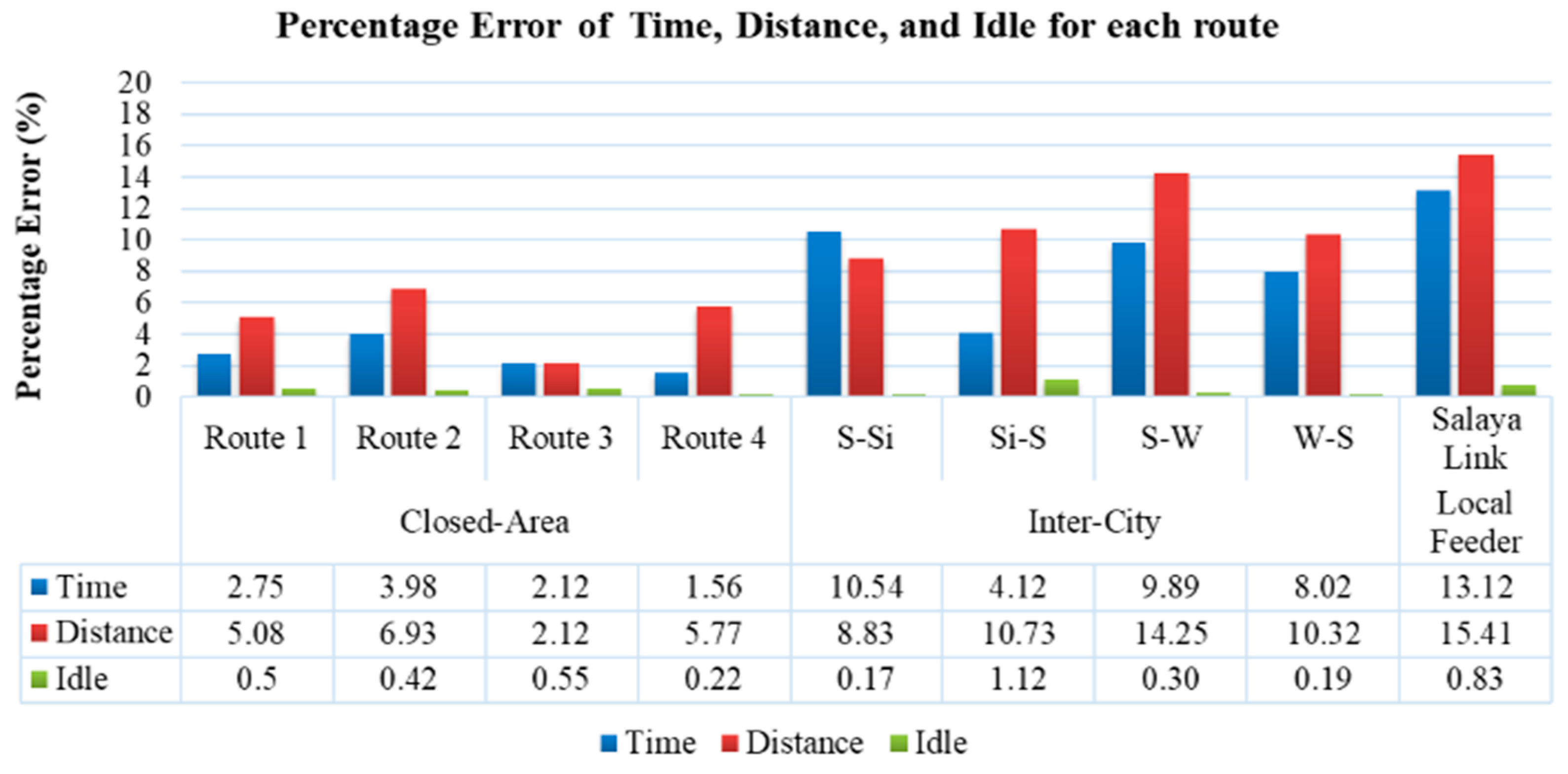
From the results, the corresponding errors between the actual and generated driving cycle could be calculated in terms of time, distance, and idle as shown in
Figure 11. It could be seen that, in general, the term of time, distance and idle that were the main control parameters were expected due to the fact that the travel time was considered in the driving cycle construction process.
The traffic of the closed-area always had the same pattern, but the inter-city and local feeder routes were affected by the traffic jam and time period of driving on the road. The maximum percentage errors of time, distance, and idle for the closed-area are 3.98%, 6.93%, and 0.55%, respectively. For inter-city, the maximum percentage errors of time, distance, and idle were 10.54%, 14.25%, and 1.12%, respectively. The maximum percentage errors for all routes of time, distance, and idle were 13.12%, 15.41%, and 0.83%, respectively. The percentage errors in this study are within acceptable values. The maximum percentage errors of time, distance, and idle of representative driving cycles of each route were within 15%, 20%, and 2%, respectively. This indicated that the driving cycle construction process by time spent of microtrips (TM) employed in this paper was suitable for all routes and driving patterns compared to the previous work [
17].
3.2. Energy Consumption
The energy consumption was calculated as function of driving speeds obtained from the generated representative driving cycles. The maximum number including standing passengers as a worst-case scenario in energy consumption was predicted for all routes. The values of traction and total energy consumption per cycle of the driving cycle for closed-area, inter-city and local feeder calculated by the MATLAB Simulink program are shown in
Table 7.
The energy consumption rate, in kWh/km, of all routes was found to be almost equivalent in each of route. Then, the average value was chosen to be the representative energy consumption rate. The estimated energy consumption of inter-city and local feeder was different from the closed-area. As can be seen in
Table 7, the traction energy consumption rate in kWh/km for all routes had a direct correlation to average velocity (
) and maximum velocity (
). The lower the average velocity is, the lower traction energy consumption rate. This study also evaluated the impact of main component and auxiliary systems including pneumatic pump, air condition, DC water cooling pump, steering pump, controller, and accessory load on the energy consumption of electric vehicles. The total energy consumption rate (
) increased to 60% compared to the traction energy consumption rate (
). It could be assumed that the EV main component and auxiliary system affect energy consumption including traffic condition, idle, etc. Therefore, it could be assumed that the energy consumption rate in this study of closed-area, inter-city, and local feeder, i.e., the average value, could be the representative energy consumption for all electric tram designs.
3.3. Battery Sizing
Table 8 presents the resulting total traction energy consumption for an entire service day in kWh of each route and minimal required power shown in
Table 9. The distance that was collected from an operation distance per day as shown in
Table 1 of each route, minimal required power, and energy consumption rate from previous sections were used to estimate minimal required battery sizing installation.
Assuming a charging scenario of and overnight recharge, the total daily required traction energy consumptions for battery size of closed-area, inter-city, and local feeder were 49 kWh, 131 kWh, and 43 kWh, respectively. The total daily required total energy consumptions for battery size of closed-area, inter-city, and local feeder were 136 kWh, 377 kWh, and, 117 kWh, respectively. The battery size depended on the charging strategy and feeder operation. If the same bus was used for all route types and could be charged only one time/day, the battery size of this bus could be at least 377 kWh. This implied that buses operated in the closed-area and local feeder can be charged after every 2–3 days of service or could be charged daily only to fill 30% of installed energy spent per day.
In addition, for a more custom design of each route, the bus could be designed in two types: one for closed-area and another for inter-city and local feeder. For closed-area, short distance for one cycle, installed battery could be at least 49 kWh, 21.71 kW without the main component and auxiliary system. Moreover, from the power profile, the maximal power of each route is 35.97 kW, 87.07 kW, and 114.24 kW for closed-area, inter-city and local feeder, respectively. This power signified the minimal required power from drivetrain and battery that can be used to design the battery.
For inter-city, the installed battery could be at least 377 kWh, 87.07 kW. However, these battery technologies have to be capable of discharging at a high C-rate. For additional different bus designs, feeder operation designs and charging plan, it was necessary to analyse from a limited technical perspective in specific areas and in economic aspects for optimization design of electric tram/bus operation.
4. Conclusions
Closed-area, inter-city, and local feeder operating routes in a suburban area of Bangkok were investigated. The trams were operated in a closed-area, while the shuttle buses were in an inter-city and a local feeder route. In the process of developing the driving cycles for energy consumption calculations, the three main operating parameters of interest were time, distance, and idle period. They were used in the development of the driving cycle as the selection criteria of suitable candidates through a comparison of their corresponding errors. The generated candidate that had the smallest percentage error was selected as the representative driving cycle in each route. Two segmentation methods, i.e., number of microtrips method (NM) and time spent on the microtrip method (TM) were employed for driving cycle development. The NM method used the amount of microtrip percentage as the parameter to develop the driving cycle but did not take into account the idle and time spent in each speed range. This resulted in excessively large percentage of errors in inter-city routes. On the other hand, the TM method considered the time spent in each microtrip and idle as parameters to develop the driving cycle. It was found that this method greatly reduced the errors that occurred in the NM method. From the above reasons, the TM method employed for the driving cycle construction process in this paper was suitable for all routes and driving patterns based on the resulting percentage errors.
The energy consumptions of trams and shuttle buses in this study were analysed from the same characteristics of vehicle, i.e., parameters, curb weight, vehicle frontal area, rolling resistance, drag coefficient, air density, and gravity acceleration. For the traction energy consumption rate, there was no significant difference between each route in closed-area, inter-city, and local feeder. Then, the average traction energy consumption of each route was considered to be the representative energy consumption rate for the design of university public service buses. The difference of traction energy consumption indicated that the driving characteristic of each route affected the energy consumption while the main EV component such as the air-conditioning system had a significant effect on the total energy consumption.
Finally, the size of the battery was analysed. The total operation distance per day and maximal power of closed-area, inter-city, and local feeder were considered to calculate a proposed size of the battery. It was suggested that only batteries for the traction energy consumption part was to be installed for the closed-area route because of a short-length service route. On the other hand, inter-city and local feeder routes exhibited high power values. Thus, battery size could be considered not only for energy consumption rate but also for maximal power for adequate driving force. The minimal required power, and energy consumption rate in this study were used to estimate minimal required battery sizing installation for each type of service route in the vicinity of Bangkok, Thailand. The results from this study could be useful for the electric vehicle system design such as required size of energy storage systems.
An interesting option for future work is a city route because of traffic characteristics in Bangkok, Thailand that imply significant amounts of idle periods between trips. The total energy consumption rate () may not only depend on a driving cycle but also idle times because an air-conditioning system would be working continuously from the starting point. The idle period is therefore expected to play a significant role, which could be of extended interest to the current study.
Author Contributions
Conceptualization, J.M. and C.-n.B.; Data curation, B.D.; Formal analysis, B.D.; Methodology, B.D., J.M. and C.-n.B.; Project administration, C.-n.B.; Resources, C.-n.B.; Software, J.M.; Supervision, J.M. and C.-n.B.; Validation, J.M., C.-n.B., P.K. and K.H.; Writing—original draft, B.D.; Writing—review and editing, J.M. and C.-n.B.
Funding
This research was funded by Thailand Advance Institute of Science and Technology, Tokyo Institute of Technology (TAIST Tokyo Tech) and National Science and Technology Development Agency (NSTDA) for providing a full scholarship, and Thailand Graduate Institute of Science and Technology (Grant No. NUIRC-M33-22-59-010M).
Acknowledgments
The authors would like to thank Lightweight Engineering Laboratory and Electrochemical Materials and System Laboratory; National Metal and Material Technology Center (MTEC), Mahidol University, and KMITL International College for their great amount of support with this work.
Conflicts of Interest
The authors declare no conflict of interest.
References
- ZeEUS EBus Report #2. 2018. Available online: https://zeeus.eu/uploads/publications/documents/zeeus-report2017-2018-final.pdf (accessed on 26 March 2018).
- Wu, X.; Freese, D.; Cabrera, A.; Kitch, W.A. Electric Vehicles’ Energy Consumption Measurement and Estimation. Transp. Res. Part D Transp. Environ. 2015, 34, 52–67. [Google Scholar] [CrossRef]
- Booklet on Thailand State of Pollution 2018. 2019. Available online: http://www.pcd.go.th/file/Booklet%20on%20Thailand%20State%20of%20Pollution%202018.pdf (accessed on 26 March 2018).
- Lajunen, A. Energy Consumption and Cost-Benefit Analysis of Hybrid and Electric City Buses. Transp. Res. Part C Emerg. Technol. 2014, 38, 1–15. [Google Scholar] [CrossRef]
- Ercan, T.; Noori, M.; Zhao, Y.; Tatari, O. On the Front Lines of a Sustainable Transportation Fleet: Applications of Vehicle-to-Grid Technology for Transit and School Buses. Energies 2016, 9, 230. [Google Scholar] [CrossRef]
- Fiori, C.; Ahn, K.; Rakha, H.A. Power-Based Electric Vehicle Energy Consumption Model: Model Development and Validation. Appl. Energy 2016, 168, 257–268. [Google Scholar] [CrossRef]
- Van Goethem, S.; Koornneef, G.; Spronkmans, S.; Hable, A. Performance of Battery Electric Buses in Practice: Energy Consumption and Range; TNO: s-Gravenhage, The Netherlands, 2013. [Google Scholar]
- Brady, J.; O’Mahony, M. Development of a Driving Cycle to Evaluate the Energy Economy of Electric Vehicles in Urban Areas. Appl. Energy 2016, 177, 165–178. [Google Scholar] [CrossRef]
- Gerssen-Gondelach, S.J.; Faaij, A.P.C. Performance of Batteries for Electric Vehicles on Short and Longer Term. J. Power Sources 2012, 212, 111–129. [Google Scholar] [CrossRef]
- Shi, S.; Lin, N.; Zhang, Y.; Cheng, J.; Huang, C.; Liu, L.; Lu, B. Research on Markov Property Analysis of Driving Cycles and Its Application. Transp. Res. Part D Transp. Environ. 2016, 47, 171–181. [Google Scholar] [CrossRef]
- Tamasnya, S.; Chungpaibulpatana, S.; Limmeechokchai, B. Development of a Driving Cycle for the Measurement of Fuel Consumption and Exhaust Emissions of Automobiles in Bangkok during Peak Periods. Int. J. Automot. Technol. 2009, 10, 251–264. [Google Scholar] [CrossRef]
- Zhu, J.; Shi, Q.; Zhou, J. The City Bus Driving Cycle Construction. In Proceedings of the 2011 2nd International Conference on Mechanic Automation and Control Engineering (MACE 2011-Proceedings), Inner Mongolia, China, 15–17 July 2011; pp. 2687–2690. [Google Scholar] [CrossRef]
- Fu, X.; Wang, H.; Cui, N.; Zhang, C. Energy Management Strategy Based on the Driving Cycle Model for Plugin Hybrid Electric Vehicles. Abstr. Appl. Anal. 2014, 2014, 341096. [Google Scholar] [CrossRef]
- De Cauwer, C.; Van Mierlo, J.; Coosemans, T. Energy Consumption Prediction for Electric Vehicles Based on Real-World Data. Energies 2015, 8, 8573–8593. [Google Scholar] [CrossRef]
- Rogge, M.; Wollny, S.; Sauer, D.U. Fast Charging Battery Buses for the Electrification of Urban Public Transport-A Feasibility Study Focusing on Charging Infrastructure and Energy Storage Requirements. Energies 2015, 8, 4587–4606. [Google Scholar] [CrossRef]
- Feroldi, D.; Carignano, M. Sizing for Fuel Cell/Supercapacitor Hybrid Vehicles Based on Stochastic Driving Cycles. Appl. Energy 2016, 183, 645–658. [Google Scholar] [CrossRef]
- Bongkotchaporn, D.; Chi-na, B.; Preecha, K.; Katsunori, H. Energy Consumption Analysis for Electric Campus Tram and Shuttle Bus Based on Real-World Driving Pattern in Thailand. In Proceedings of the 2018 JSAE Annual Congress (Spring), Pacifico Yokohama, Japan, 23–25 May 2018. [Google Scholar]
Figure 1.
Closed-area routes (a) Route1; (b) Route2; (c) Route 3; (d) Route 4.
Figure 1.
Closed-area routes (a) Route1; (b) Route2; (c) Route 3; (d) Route 4.
Figure 2.
Inter-City Routes: (a) Salaya-Wit; (b) Wit-Salaya; (c) Salaya-Siriraj; (d) Siriraj-Salaya.
Figure 2.
Inter-City Routes: (a) Salaya-Wit; (b) Wit-Salaya; (c) Salaya-Siriraj; (d) Siriraj-Salaya.
Figure 3.
Local Feeder Routes: Salaya Link.
Figure 3.
Local Feeder Routes: Salaya Link.
Figure 4.
Microtrip separation process.
Figure 4.
Microtrip separation process.
Figure 5.
Driving cycle construction procedure flow chart.
Figure 5.
Driving cycle construction procedure flow chart.
Figure 6.
The example of the generated of driving cycle.
Figure 6.
The example of the generated of driving cycle.
Figure 7.
MATLAB Simulink for energy consumption calculation.
Figure 7.
MATLAB Simulink for energy consumption calculation.
Figure 8.
Closed-area representative driving cycle (tram): (a) Route 1; (b) Route 2; (c) Route 3; (d) Route 4.
Figure 8.
Closed-area representative driving cycle (tram): (a) Route 1; (b) Route 2; (c) Route 3; (d) Route 4.
Figure 9.
Inter-city representative driving cycle (shuttle bus): (a) Salaya-Wit; (b) Wit-Salaya; (c) Salaya-Siriraj; (d) Siriraj-Salaya.
Figure 9.
Inter-city representative driving cycle (shuttle bus): (a) Salaya-Wit; (b) Wit-Salaya; (c) Salaya-Siriraj; (d) Siriraj-Salaya.
Figure 10.
Local feeder representative driving cycle (Salaya link).
Figure 10.
Local feeder representative driving cycle (Salaya link).
Figure 11.
Corresponding percentage error of time, distance and idle for each route.
Figure 11.
Corresponding percentage error of time, distance and idle for each route.
Table 1.
Summary of data collection processes: routes and equipment.
Table 2.
Closed-area characteristics per cycle for each route.
Table 2.
Closed-area characteristics per cycle for each route.
| Route | Velocity (km/h) | Tlimit (h:mm:ss) | Passengers (Person) |
|---|
| Vsd | Vavg | Vmax | Mean | Max |
|---|
| 1 | 1.616 | 15.620 | 58.630 | 0:13:22 | 5 | 34 |
| 2 | 1.242 | 17.732 | 41.483 | 0:19:49 | 9 | 30 |
| 3 | 2.163 | 16.258 | 40.135 | 0:21:15 | 13 | 48 |
| 4 | 1.253 | 15.098 | 36.744 | 0:14:55 | 6 | 44 |
Table 3.
Inter-city characteristics per cycle for each route.
Table 3.
Inter-city characteristics per cycle for each route.
| Route | Velocity (km/h) | Tlimit (h:mm:ss) | Passengers (Person) |
|---|
| Vsd | Vavg | Vmax | Mean | Max |
|---|
| S-Wit | 5.8 | 26.27 | 85.44 | 1:01:15 | 27 | 63 |
| Wit-S | 4.9 | 24.85 | 93.78 | 1:01:06 |
| S-Si | 4.05 | 31.99 | 86.9 | 0:39:18 |
| Si-S | 3.49 | 19.3 | 84.26 | 0:52:03 |
Table 4.
Local feeder characteristics per cycle for each route.
Table 4.
Local feeder characteristics per cycle for each route.
| Route | Velocity (km/h) | Tlimit (h:mm:ss) | Passengers (Person) |
|---|
| | | Mean | Max |
|---|
| Salaya Link | 6.76 | 32.06 | 101.46 | 1:21:55 | 22 | 44 |
Table 5.
Parameters for energy consumption calculation.
Table 5.
Parameters for energy consumption calculation.
| General Characteristics of Vehicle (Medium-Sized Bus) |
|---|
| Parameters | Value |
| Curb weight (kg) | 9000 |
| Vehicle frontal area (m2) | 7.5 |
| Rolling Resistance | 0.0015 |
| Drag coefficient | 0.7 |
| Air Density (kg/m3) | 0.114 |
| Gravity Acceleration (m/s2) | 9.8 |
Table 6.
Parameters of components and auxiliary system for energy consumption calculation.
Table 6.
Parameters of components and auxiliary system for energy consumption calculation.
| Components | Load (kW) |
|---|
| Pneumatic pump | 2.2 |
| Air condition | 10 |
| DC water cooling pump | 0.06 |
| Steering pump and controller | 1.5 |
| Accessory load | 0.5 |
Table 7.
Traction and total energy consumption rate in kWh/km.
Table 7.
Traction and total energy consumption rate in kWh/km.
| Energy Consumption Rate (kWh/km) | Closed-Area | Inter-City | Local Feeder |
|---|
| 0.522 | 0.691 | 0.698 |
| 1.438 | 1.988 | 1.894 |
Table 8.
Estimated minimal required battery sizing of each route.
Table 8.
Estimated minimal required battery sizing of each route.
| Closed-Area | Inter-City | Local Feeder |
|---|
| Traction | 49 | 131 | 43 |
| Total | 136 | 377 | 117 |
Table 9.
Maximum power of each route.
Table 9.
Maximum power of each route.
| Pmax (kW) | Closed-Area | Inter-City | Local Feeder |
|---|
| Traction | 21.71 | 72.81 | 99.98 |
| Total | 35.97 | 87.07 | 114.24 |
© 2019 by the authors. Licensee MDPI, Basel, Switzerland. This article is an open access article distributed under the terms and conditions of the Creative Commons Attribution (CC BY) license (http://creativecommons.org/licenses/by/4.0/).
