Abstract
Classical fractional order controller tuning techniques usually consider the frequency domain specifications (phase margin, gain crossover frequency, iso-damping) and are based on knowledge of a process model, as well as solving a system of nonlinear equations to determine the controller parameters. In this paper, a novel auto-tuning method is used to tune a fractional order PI controller. The advantages of the proposed auto-tuning method are two-fold: There is no need for a process model, neither to solve the system of nonlinear equations. The tuning is based on defining a forbidden region in the Nyquist plane using the phase margin requirement and determining the parameters of the fractional order controller such that the loop frequency response remains out of the forbidden region. Additionally, the final controller parameters are those that minimize the difference between the slope of the loop frequency response and the slope of the forbidden region border, to ensure the iso-damping property. To validate the proposed method, a case study has been used consisting of a pick and place movement of an UR10 robot. The experimental results, considering two different robot configurations, demonstrate that the designed fractional order PI controller is indeed robust.
1. Introduction
Auto-tuning methods are among the most suitable and popular controller design methods for the industry. The reason lies in the elimination of the need for a process model in the tuning of the controller parameters. For PID controllers, several auto-tuning methods have been developed throughout the years. However, this is not the case of fractional order PID controllers.
Fractional calculus represents an emerging field of research that has gained increased interest in control applications [1]. The fractional order PID controller is a generalization of the classical one, with the integral and derivative terms modified to accommodate fractional orders. To tune these types of controllers, a couple of methods exist; however, most of these require a process model. The auto-tuning methods for fractional order controllers are in their early stages. Such a method is the so-called phase shaper [2,3]. This is in fact a traditional PID controller with a twist: It has a fractional order integrator or differentiator sα, with α∈(−1, 1). The aim of this phase shaper is to achieve closed loop robustness to gain variations. A different approach to auto-tuning of fractional order PIDs is based on a two-step design that first produces a fractional order PI (FO-PI) controller, and then a fractional order PD controller with a filter. A relay test is used in this regard [4]. The design is intended to achieve a certain gain crossover frequency and phase margin, while ensuring the iso-damping property. The procedure is lengthy and is based on maximizing the robustness to plant gain variations. Other auto-tuning methods based on the relay test have been proposed, such as for the design of a FO-PI controller for real-time steam temperature control ([5] new). The relay test is also used in Reference ([6] new) for the auto-tuning of two types of fractional order PI controllers with an iso-damping property for a class of unknown, stable and minimum phase plants. The FO-PI controllers designed by the two methods ensure that the phase Bode plot is flat at a given frequency called the tangential frequency. An iterative procedure is used in this case, since several relay feedback tests are used to identify the plant gain and phase at the tangential frequency. Only simulation results are presented. An iterative procedure combined with the relay test is also used for designing fractional order lead-lag compensators ([7] new). The same relay test has been proposed in Reference ([8] new) for the auto-tuning of a fractional order PID controller for second order plus dead time plants. In this design, firstly, the process dynamics of overdamped, underdamped, and critically damped plants are modelled by using an offline relay-based method, where a maximum of four unknown parameters are determined in the simplest possible way. Although this is a clear limitation of the method, a great variety of plants can be modeled using four parameters only, such as the second order plus dead time processes. A relay with hysteresis is used to obtain the describing function. As performance specifications, the gain margin and phase margin, as well as the iso-damping property are used to tune the five parameters of the controller. A significant advantage of the proposed tuning method is that a priori information of the system’s gain and phase crossover frequencies is not required while tuning the controller. The proposed method is validated through simulation studies in a class of process models, and also verified experimentally on a coupled tank system.
In Reference ([9] new), experimental validations of an auto-tuning method for fractional order PID controllers, and its implementation on hardware in the loop simulator for real-time control of unknown plants are presented. The application of the auto-tuning procedure is limited to systems with delay and an order greater than one, while the performance specifications refer to the crossover frequency, phase margin and the iso-damping property. The auto-tuning procedure consists of two phases: The first one is dedicated to the identification of the process at the desired crossover frequency and the second one to determine all the parameters of the fractional order PID controllers. Experimental validations are also presented in Reference ([10] new), where a model-free tuning method of an FO-PI controller and its application for the speed regulation of a permanent magnet synchronous motor (PMSM) is described. Here, virtual reference feedback tuning is used to determine the parameters of the FO-PI controller. Under the lack of accurate models, the proposed model-free method depends only on the measured input–output data of the closed-loop PMSM servo system. Also, Bode’s ideal transfer function is incorporated into the virtual reference feedback tuning with consideration of the systematic fractional dynamics. Optimal performance constraints are taken into consideration by the proposed method, such as stability requirements, sensitivity criteria, frequency-domain and time-domain characteristics. Based on these, a comprehensive optimization problem is derived and solved, such that the robustness and disturbance rejection ability of the resulting FO-PI controller are enhanced to achieve optimal performance. In Reference ([11] new), the problem of fractional modeling and the control of an industrial selective compliant assembly robot arm (SCARA) is presented. Induction motors are used to drive each joint of the robot manipulator and for each motor a fractional model is formulated. For comparison purposes, both integer order and fractional order controllers are designed. The tuning procedure is based on a Particle swarm optimization algorithm, with the ITAE index used as a cost function to be minimized. Only numerical simulations are included to show the effectiveness of the fractional order controllers.
The same performance specification set (phase margin, gain crossover frequency and iso-damping) is considered in the design of fractional order controllers based on a combination of the Ziegler-Nichols tuning procedure and the Åström-Hägglund method [12]. First, the proportional and integral gains of the fractional order controller are computed based on the Ziegler-Nichols approach, then the derivative gain is obtained using the Åström-Hägglund method [13,14]. An optimization procedure is required to solve the resulting nonlinear equations. The core idea is that, in case of a better step response of the closed loop system, an optimization model is used, with the previously computed controller parameters taken as initial values. The result of the optimization consists in new values for the controller parameters, considered to be optimal.
The same three frequency domain specifications are considered also in Reference [15]. The auto-tuning method can be used to determine either fractional order PI or PD controllers. In this case, a simple sine test is used to determine the required process information for the tuning of the fractional order controller, then, much like in most of the fractional order controller design methods, either a graphical approach or an optimization routine is required to solve the resulting system of nonlinear equations.
A novel auto-tuning approach for fractional order PI controllers, the FO-KC method, is presented in this paper. The idea comes as an extension of a previously designed autotuning method for integer order PID controllers, namely the KC autotuner [16]. The tuning of fractional order PI controllers using the FO-KC auto-tuning method is similar to the classical tuning methods in the sense that it determines the three controller parameters using three performance specifications: the gain crossover frequency ωc, the phase margin PM and the iso-damping property. These three performance specifications are quite frequently used as design specifications and lead to a system of nonlinear equations that need to be solved to estimate the FO-PI parameters. However, this can be time consuming. The FO-KC autotuning method eliminates this drawback. The design is based on using the iso-damping property and the phase margin PM requirement to define a forbidden region in the Nyquist plane that the loop frequency response should avoid. Moreover, to ensure the iso-damping property, the optimal FO-PI controller is determined such that the difference between the slope of the loop frequency response and the slope of the forbidden region border is minimum. The FO-KC auto-tuning method has been presented before [17], however, it has only been tested under simulations. The main contribution of the present paper is to offer an experimental validation of the method and this represents the original element of the present work.
2. The Proposed Fractional Order Auto-Tuning Method
The FO-KC auto-tuning method is used in this paper to determine the parameters of a FO-PI controller with the transfer function as indicated next:
where kp and ki represent the proportional and integral gains and λ is the fractional order, with λmin < λ < 2. The minimum value of the fractional order can be easily computed using Reference [18]. The basic idea of the FO-KC auto-tuning method resides in determining the three parameters in (1) using three performance specifications: the gain crossover frequency ωc, the phase margin PM and the iso-damping property. As mentioned in the Introduction section, the design is based on using the iso-damping property and the phase margin PM requirement to define a forbidden region in the Nyquist plane. Moreover, to ensure the iso-damping property, the optimal FO-PI controller is determined such that the difference between the slope of the loop frequency response and the slope of the forbidden region border is minimum. Figure 1 shows the forbidden region, where the center, C, and its radius, R, are determined using trigonometric relations based on the PM value:
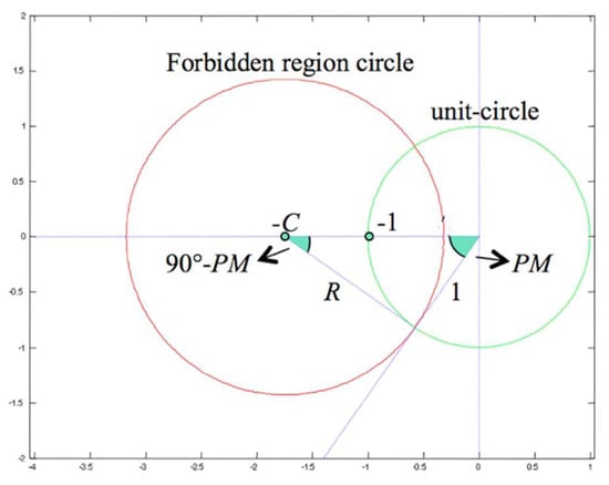
Figure 1.
Forbidden region for the FO-KC auto-tuning method.
The first step in designing the FO-PI controller using the proposed auto-tuning method consists in determining the forbidden region using (2). As it has been previously mentioned, the key point in the design consists in evaluating for the imposed gain crossover frequency, the difference between the slope of the forbidden region border and that of the loop frequency response:
where stands for the slope of the forbidden region border and is the slope of the loop frequency response.
The second step in the design consists in the computation of the slope of the forbidden region border, based on trigonometric relations in Figure 1:
where . The slope of the loop frequency response can be computed according to the following two equations:
where is the loop frequency response, is the process frequency response at the gain crossover frequency, is the derivative of the process frequency response, and are the controller frequency response and its derivative at the gain crossover frequency. To determine the real and imaginary parts in (6), all terms in the right hand side of (5) have to be computed.
The third step in the design consists in a simple sine test performed on the process, with the frequency equal to the gain crossover frequency. Based on this, the process frequency response and its slope can be easily determined [19]. Other techniques can also be used to determine the process frequency response and its corresponding slope at the gain crossover frequency.
The controller frequency response can be computed considering the following relation:
where , with the modulus = 1, at the gain crossover frequency, and the phase . Replacing (1) in (7), leads to the following results:
with . Once a and b are determined as in (7), the controller parameters in (8) depend solely on λ. The derivative of the controller frequency response can be computed numerically once the parameters of the FO-PI controller are determined.
The last step of the FO-KC auto-tuning method consists in taking small increments for the fractional order λ in the range λmin < λ < 2 and computing the parameters in (8) as well as and . Then, evaluation of (5) leads to the real and imaginary parts in (6) required to compute the slope of the frequency response at the gain crossover frequency. For each λ in the range λmin < λ < 2, it is then possible to evaluate the difference in (3) and select the minimum value. This then results in the optimal FO-PI controller.
3. Experimental Validation: FO-PI Design for a UR10 Robot
Manipulator robots, Figure 2, represent one of the biggest class of robots which are used in the factory environment. The relationship between the actuation and the contact forces, which are acting on the robot, is given by the dynamic equation of motion.
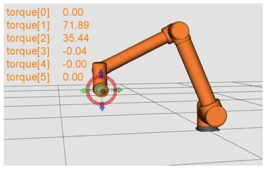
Figure 2.
Schematic overview of the UR10 robot—CAD model.
The kinematic model of a manipulated robot can be expressed as a series of rigid bodies connected by joints [20]. The dynamics of the robot can be defined using spatial vector notation or canonical equations (which are also used in this study). There are two canonical forms used to describe the equation of motion, the joint space formulation:
and the operational space formulation:
where represent the joint variables (the generalized joint coordinates, the velocity and the acceleration), M(q) is the inertia matrix, is the n × 1 vector of the Coriolis and centrifugal forces, G(q) is the gravity force. The parameters x, v and F represent the operational space coordinates, the velocity of the end-effector and the force exerted on the end-effector, while Λ is the operational space inertia matrix, Y is the vector of the velocity product and Φ is the vector of gravity term. The two canonical forms are related and thus the following relation can be given:
where J is the Jacobian matrix of the manipulated robot.
In most of the robotics applications, one needs to control the pose of the end-effector, which can be done through the direct kinematics formulation. The direct kinematics can be calculated via the Denavit-Hartenberg (D-H) formulation [21]. In this research study, a 6-degrees of freedom manipulator robot is considered, thus the direct kinematic equation is given as:
where , i = 1, 6 represents the homogeneous transformation matrices defined as:
where the parameters θi, ai, di, αi represent the D-H parameters related to joint i. These parameters associated to the UR10 robot considered in this study are given in Table 1.

Table 1.
D-H parameters for UR10 robot.
Nowadays, a large number of the industrial robots are driven by brushless servo motors. Several studies in the area of control of manipulator robots consider Cartesian coordinates as control variables. However, in order to obtain the desired Cartesian trajectory for the end-effector attached to the robot, each joint axis must follow a specific trajectory. The common approach to control the robot joints is based on the decentralized techniques, which consider an independent controller for each joint. In this study, the manipulated variable was considered as being the applied voltage Va, while the controlled variable is the position θ(t). In the case of speed control, the controlled variable is the angular velocity ω(t). The dynamics of a motor attached to a joint j can be defined as:
with τc the Coulomb’s law of friction, B the viscous friction, Km is the motor torque, Ka is the transconductance of the amplifier and Jm the total inertia seen by the motor for joint j. For simplification reasons, if the Coulomb friction from Equation (14) is ignored, the equivalent Laplace transform of (14) is given by:
where Ω(s) and Va(s) are the Laplace transform of their corresponding signal from time domain ω and Va. Thus, the transfer function of a motor drivetrain attached to a robot joint can be written as:
However, for the purpose of designing the fractional order PI controller using the FO-KC auto-tuning principle, there is no need to determine the parameters of the actual model in (16), but only its frequency response at a selected gain crossover frequency, as well as the corresponding frequency response slope. The gain crossover frequency selected for the UR10 robot is ωc = 15.7 rad/s. A sine signal is applied on the robot reference as indicated next and shown in Figure 3:
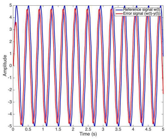
Figure 3.
Signals used to determine the robot frequency response and the corresponding frequency response slope at the gain crossover frequency.
It is important to note that an open loop response is impossible to obtain, therefore a closed loop test is performed with a simple P controller, with a proportional gain kp = 15. Using this information, along with some filtering techniques [19,22], it is possible to obtain the required robot frequency response and its corresponding frequency response slope:
The imposed phase margin to design the FO-PI controller in (1) is selected as PM = 60°. The forbidden region center C, and its radius, R, are determined using (2):
The slope of the forbidden region border is next computed according to (6):
where .
The controller frequency response can be computed considering (5):
where the loop frequency response is .
Performing now the last step of the FO-KC auto-tuning method implies taking small increments for the fractional order λ and computing the parameters of the FO-PI, as well as the slope of the loop frequency response. Then, for each fractional order λ, it is possible to evaluate the difference in (3) and select the minimum value. This then results in the optimal FO-PI controller:
To implement the controller in (23), a novel direct discretization method is used [23]. The approximation of the FO-PI controller to a discrete-time equivalent of order 4 is done using a sampling period of 0.1 s. The frequency response of the FO-PI controller in (23) and its discrete-time approximation is given in Figure 4.
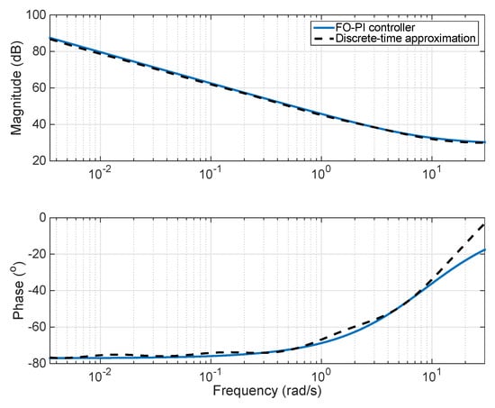
Figure 4.
Frequency response of the FO-PI controller and its discrete-time approximation.
The performance of the fractional order controller in (23), designed using the FO-KC auto-tuning method, has been evaluated in a real time application using a UR10 robot considering a pick and place movement. Since joints 2 and 3 have larger variation in comparison with other joints, the designed controller was implemented and applied to these joints. Multiple experiments were conducted in order to validate and test the robustness of the controller. For the pick and place task, the first experiment was conducted using the next configuration [−60, −25, −50, −30, 170, 260] and the obtained results are given in Figure 5 and Figure 6.
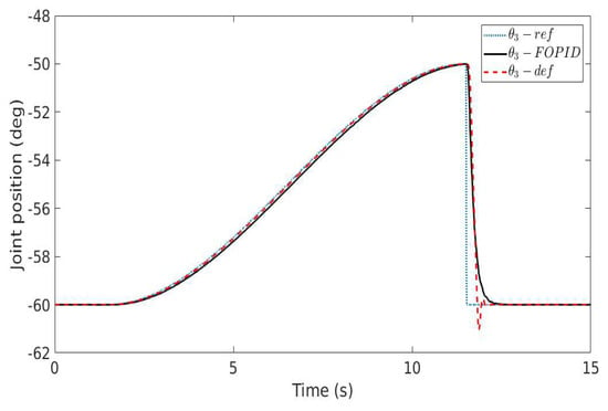
Figure 5.
Step response of the UR10 robot for joint 3—the first robot configuration (ref = reference signal, FOPID = closed loop response with FO-PI controller in (23), def = default robot PID controller).
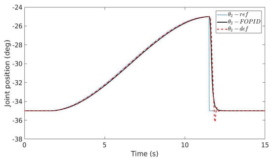
Figure 6.
Step response of the UR10 robot for joint 2—the first robot configuration (ref = reference signal, FOPID = closed loop response with FO-PI controller in (23), def = default robot PID controller).
The second experiment provided in this paper made use of the following configuration [120, −70, −125, 65, −30, 90] and the results are illustrated in Figure 7 and Figure 8. It can be easily noticed that compared to the default PID controller running on the robot, the FO-PI controller in (23) produces improved closed loop results: The settling time is fast, similar to the default controller; however, there is no overshoot. A further conclusion by comparing the closed loop result in Figure 5, Figure 6, Figure 7 and Figure 8 shows that the FO-PI controller is also robust, since the new robot configuration does not lead to an increase in the overshoot, as in the case of the default controller.
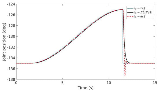
Figure 7.
Step response of the UR10 robot for joint 3—the second robot configuration (ref = reference signal, FOPID = closed loop response with FO-PI controller in (23), def = default robot PID controller).
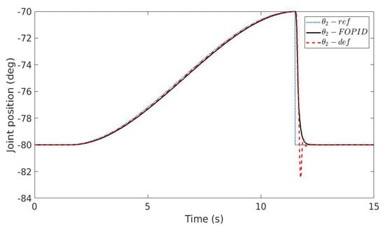
Figure 8.
Step response of the UR10 robot for joint 2—the second robot configuration (ref = reference signal, FOPID = closed loop response with FO-PI controller in (23), def = default robot PID controller).
4. Conclusions
The paper presents an experimental validation of a novel auto-tuning method for robust fractional order controllers. The auto-tuning method extensively simplifies the classical tuning techniques for fractional order controllers that imply the use of a process model, as well as the need to solve a system of nonlinear equations. The advantage of the proposed auto-tuning method resides in the fast and simple extraction of all process information required for the tuning, as well as in producing controllers robust to gain uncertainties.
The tuning of the fractional order controllers using the FO-KC auto-tuning method is based on determining a forbidden region in the Nyquist plane using the phase margin requirement and computing the parameters of the fractional order controller such that the loop frequency response avoids entering the forbidden region. Moreover, to ensure the iso-damping property, the optimal FO-PI controller is selected as the one that minimizes the difference between the slope of the loop frequency response and the slope of the forbidden region border.
To validate the proposed method, a case study has been used consisting of a pick and place movement of an UR10 robot. The experimental results, considering two different robot configurations, demonstrate that the designed fractional order PI controller is indeed robust.
Further work includes comparisons with other auto-tuning methods to demonstrate the benefits of using the proposed algorithm. Also, a detailed analysis regarding the computational cost and a comparison in terms of accuracy and computational cost with other methods existing in the literature can be considered, as well as a theoretical analysis to demonstrate the convergence of the proposed method and to support the experimental results.
Author Contributions
C.M. and I.B. designed the FO-PI controller based on experimental data, analyzed the results and wrote the paper, C.I. determined the process frequency response and its corresponding slope information required for the tuning of the controller, R.D.K. developed the auto-tuning method, C.C. and S.V. implemented the controller and performed the experimental tests.
Funding
“This research was partially funded by the Romanian Ministery of Research and Innovation, CNCS—UEFISCDI, project number PN-III-P1-1.1-TE-2016-1396, within PNCDI III and by the BOF - STIMPRO funding of the University of Antwerp”.
Acknowledgments
This work was supported by a grant of the Romanian Ministery of Research and Innovation, CNCS—UEFISCDI, project number PN-III-P1-1.1-TE-2016-1396.
Conflicts of Interest
The authors declare no conflict of interest.
References
- Vilanova, R.; Visioli, A. PID Control in the Third Millennium; Springer: London, UK, 2012; ISBN 978-1-4471-2424-5. [Google Scholar]
- Chen, Y.Q.; Moore, K.L.; Vinagre, B.M.; Podlubny, I. Robust PID controller autotuning with a phase shaper. In Proceedings of the First IFAC Workshop on Fractional Differentiation and Its Applications, Bordeaux, France, 19–21 July 2004; pp. 162–167. [Google Scholar]
- Chen, Y.Q.; Moore, K.L. Relay feedback tuning of robust PID controllers with iso-damping property. Trans. Syst. Man. Cybern. 2005, 35, 23–31. [Google Scholar] [CrossRef]
- Monje, C.A.; Vinagre, B.M.; Feliu, V.; Chen, Y.Q. Tuning and auto-tuning of fractional order controllers for industry applications. Control Eng. Pract. 2008, 16, 798–812. [Google Scholar] [CrossRef]
- Tajjudin, M.; Tahir, S.F.; Fazalul Rahiman, M.H.; Mohd Arshad, N.; Adnan, R. Fractional-order PI controller with relay auto-tuning method. In Proceedings of the IEEE 4th Control and System Graduate Research Colloquium (ICSGRC), Shah Alam, Malaysia, 19–20 August 2013. [Google Scholar] [CrossRef]
- Wang, C.Y.; Jin, Y.S.; Chen, Y.Q. Auto-tuning of FOPI and FO [PI] Controllers with Iso-damping Property. In Proceedings of the Joint 48th IEEE Conference on Decision and Control and 28th Chinese Control Conference, Shanghai, China, 16–18 December 2009; pp. 7309–7314. [Google Scholar]
- Monje, C.A.; Chen, Y.Q.; Vinagre, B.M.; Xue, D.; Feliu, V. Fractional-Order Systems and Controls Fundamentals and Applications; Springer: London, UK, 2010; ISBN 978-1-84996-334-3. [Google Scholar]
- Baruah, G.; Majhi, S.; Mahanta, C. Auto-tuning of Fractional Order PID Controller for a Class of Processes and Experimental Validation Using a Coupled Tank System. Control Syst. Eng. 2016, 4, 121–140. [Google Scholar] [CrossRef]
- Caponetto, R.; Dongola, G.; Pappalardo, F.; Tomasello, V. Auto-Tuning and Fractional Order Controller Implementation on Hardware in the Loop System. J. Optim. Theory Appl. 2013, 156, 141–152. [Google Scholar] [CrossRef]
- Xie, Y.; Tang, X.; Song, B.; Zhou, X.; Guo, Y. Model-free tuning strategy of fractional-order PI controller for speed regulation of permanent magnet synchronous motor. Trans. Inst. Meas. Control 2018. [Google Scholar] [CrossRef]
- Coronel-Escamilla, A.; Torres, F.; Gómez-Aguilar, J.F.; Escobar-Jiménez, R.F.; Guerrero-Ramírez, G.V. On the trajectory tracking control for an SCARA robot manipulator in a fractional model driven by induction motors with PSO tuning. Multibody Syst. Dyn. 2017, 43, 257–277. [Google Scholar] [CrossRef]
- Yeroglu, C.; Onat, C.; Tan, N. A new tuning method for PIλDμ controller. In Proceedings of the International Conference on Electrical and Electronics Engineering ELECO, Bursa, Turkey, 5–8 November 2009; pp. 312–316. [Google Scholar]
- Åström, K.J.; Hägglund, T. Automatic tuning of simple regulators with specifications on phase and amplitude margins. Automatica 1984, 20, 645–651. [Google Scholar] [CrossRef]
- Åström, K.J.; Hägglund, T. Revisiting the Ziegler–Nichols step response method for PID control. J. Process. Control 2004, 14, 635–650. [Google Scholar] [CrossRef]
- De Keyser, R.; Muresan, C.I.; Ionescu, C. A Novel Auto-tuning Method for Fractional Order PI/PD Controllers. ISA Trans. 2016, 62, 268–275. [Google Scholar] [CrossRef] [PubMed]
- De Keyser, R.; Ionescu, C.I.; Muresan, C.I. Comparative Evaluation of a Novel Principle for PID Autotuning. In Proceedings of the Asian Control Conference, Gold Coast, Australia, 18–21 December 2017; pp. 1164–1169. [Google Scholar]
- Muresan, C.I.; De Keyser, R.; Birs, I.; Copot, D.; Ionescu, C. Benchmark Challenge: A robust fractional order control autotuner for the Refrigeration Systems based on Vapor Compression. In Proceedings of the IFAC Conference on Advances in Proportional-Integral-Derivative Control, Ghent, Belgium, 9–11 May 2018; pp. 31–36. [Google Scholar]
- Muresan, C.I.; Birs, I.R.; Ionescu, C.M.; De Keyser, R. Tuning of fractional order PI/PD controllers based on existence conditions. Proc. Inst. Mech. Eng. 2018. under review. [Google Scholar]
- De Keyser, R.; Muresan, C.I.; Ionescu, C. ,A single sine test can robustly estimate a system’s frequency response slope. Int. J. Syst. Sci. 2108. under review. [Google Scholar]
- Spong, M.; Hutchinson, S.; Vidyasagar, M. Robot Modeling and Control, 1st ed.; Wiley: New York, NY, USA, 2006; ISBN 0471765791. [Google Scholar]
- Siciliano, B.; Sciavicco, L.; Villani, L.; Oriolo, G. Robotics, Modelling, Planning and Control; Springer: London, UK, 2009; ISBN 978-1-84628-641-4. [Google Scholar]
- Copot, C.; Muresan, C.I.; Ionescu, C.; Vanlanduit, S.; De Keyser, R. Automatic calibration of UR10 robot through simple auto-tuning approach. Robotics 2018. under review. [Google Scholar]
- De Keyser, R.; Muresan, C.I.; Ionescu, C.M. An efficient algorithm for low-order direct discrete-time implementation of fractional order transfer functions. ISA Trans. 2018, 74, 229–238. [Google Scholar] [CrossRef] [PubMed]
© 2018 by the authors. Licensee MDPI, Basel, Switzerland. This article is an open access article distributed under the terms and conditions of the Creative Commons Attribution (CC BY) license (http://creativecommons.org/licenses/by/4.0/).