Effect of Periodic Water Clusters on AISI 304 Welded Surfaces

 ,
,  ,
,  and
and 
Abstract
1. Introduction
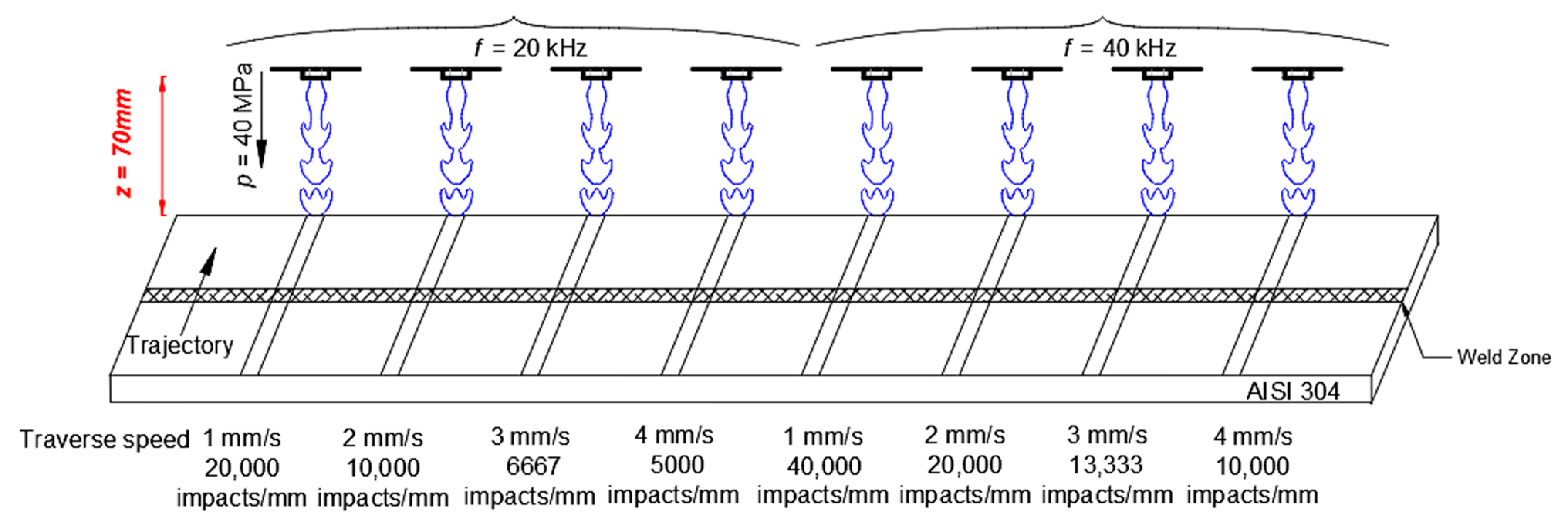
2. Materials and Methods
3. Results
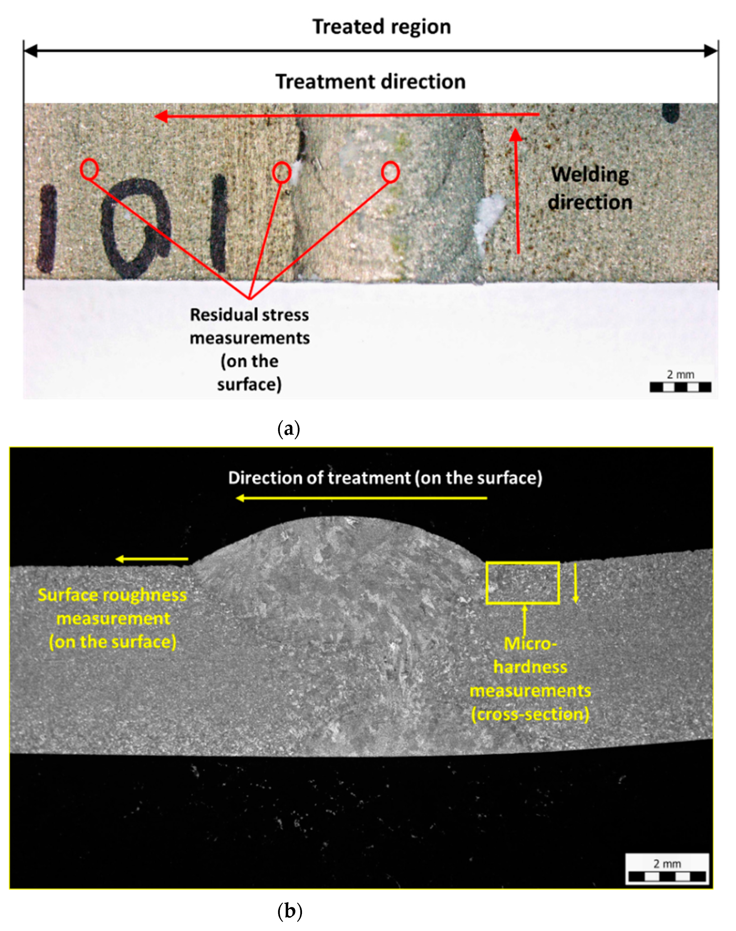
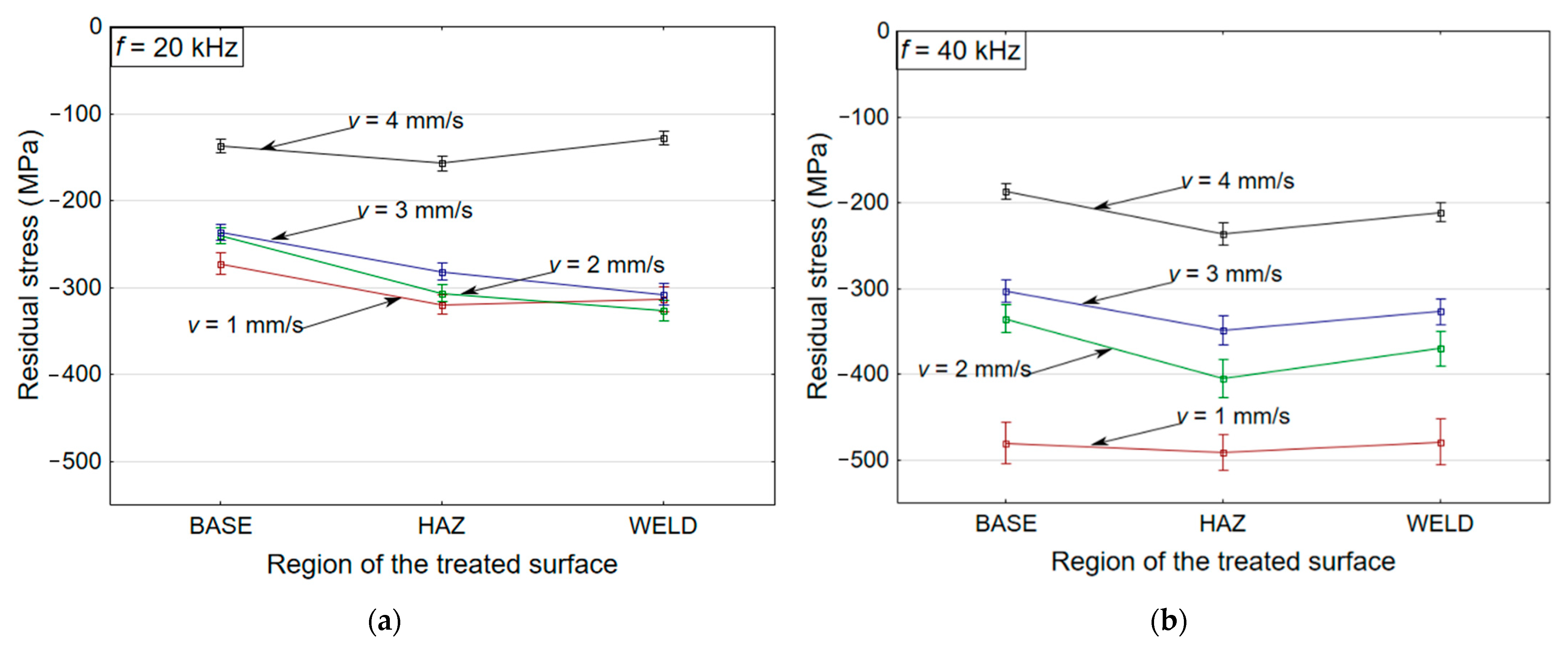
3.1. Surface Residual Stress Measurements
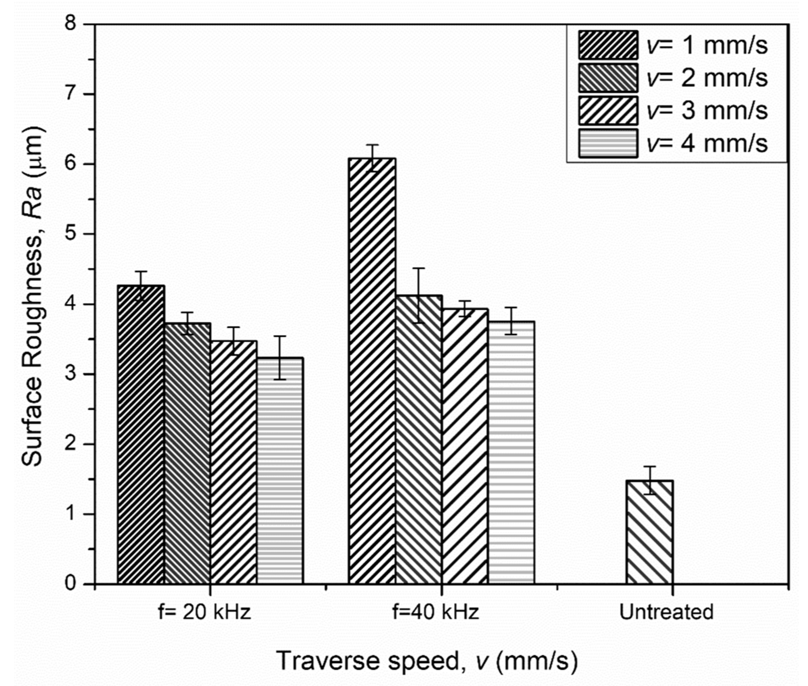
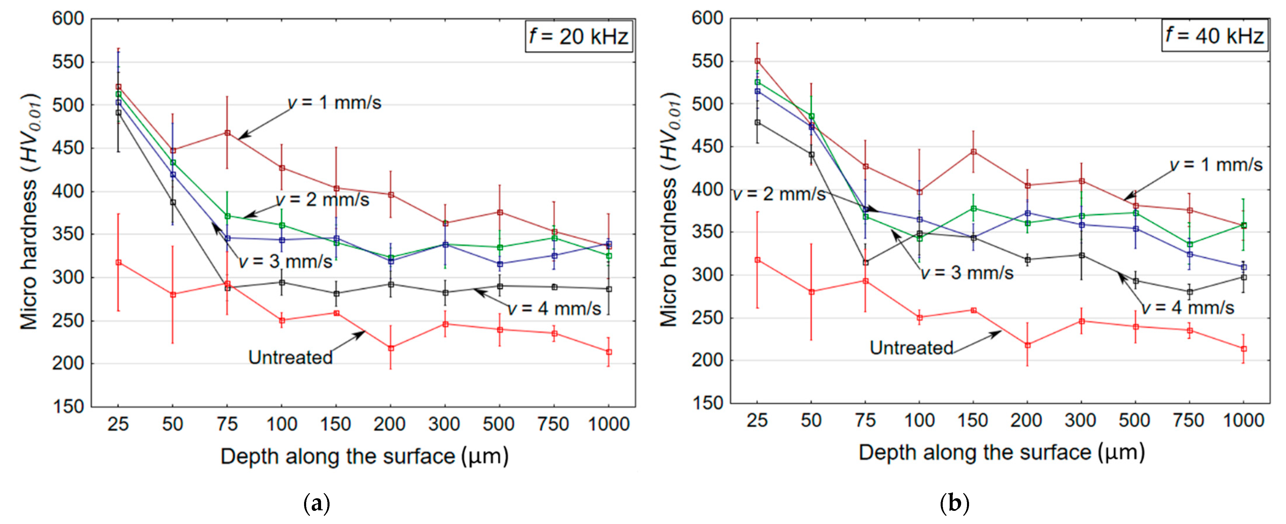
3.2. Surface Roughness and Microhardness Measurements
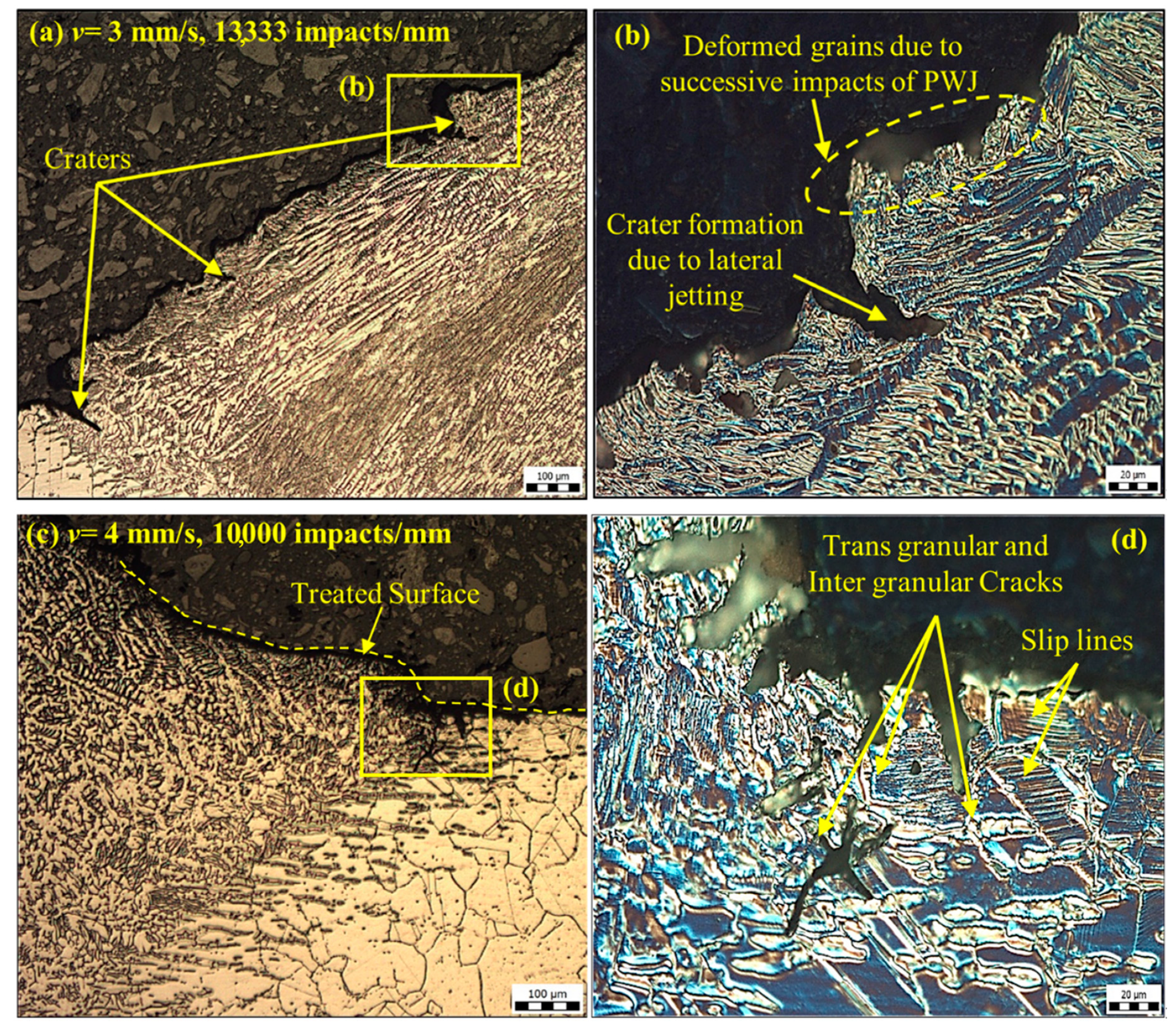
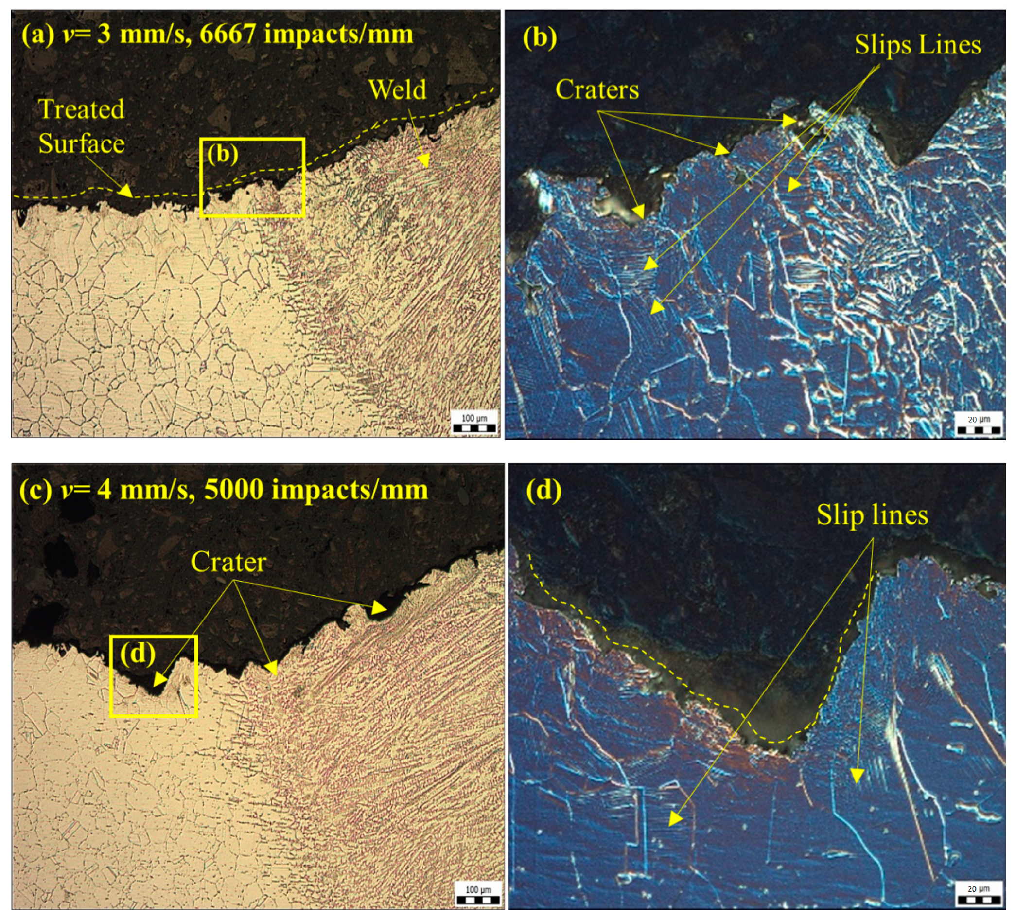
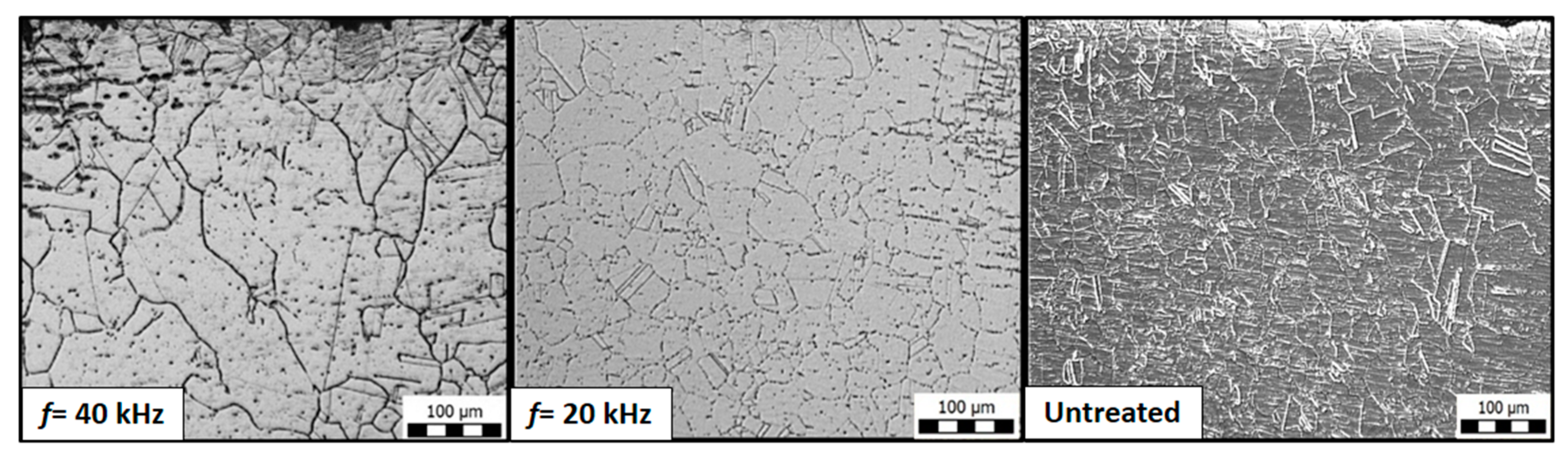
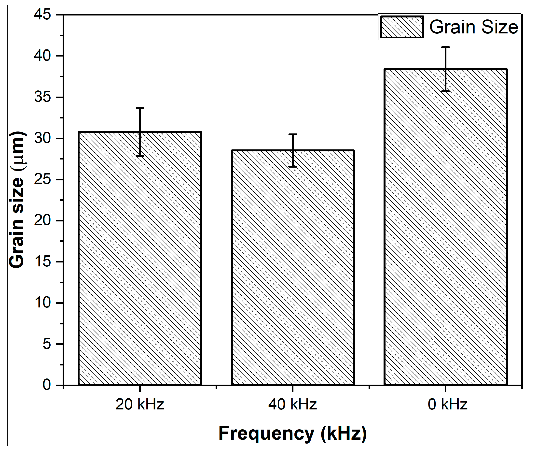
3.3. Optical Microscopy
4. Conclusions
Author Contributions
Funding
Institutional Review Board Statement
Informed Consent Statement
Data Availability Statement
Acknowledgments
Conflicts of Interest
References
- Ju, D.; Han, B. Investigation of water cavitation peening-induced microstructures in the near-surface layer of pure titanium. J. Mater. Process. Technol. 2009, 209, 4789–4794. [Google Scholar] [CrossRef]
- Marín, J.F.S.; Blanco, J.; Giraldo, J.; Toro, A. Cavitation erosion of martensitic and austenitic stainless steel welded coatings. Wear 2011, 271, 1445–1453. [Google Scholar] [CrossRef]
- Wang, Z.; Kang, Y.; Wang, X.; Li, D.; Shi, H. Effects of modulation position on the impact performance of mechanically modulated pulsed water jet. J. Manuf. Process. 2020, 56, 510–521. [Google Scholar] [CrossRef]
- Foldyna, J. Use of Acoustic Waves for Pulsating Water Jet Generation. In Acoustic Waves—From Microdevices to Helioseismology; IntechOpen: London, UK, 2011; pp. 323–342. [Google Scholar] [CrossRef]
- Richman, R.H.; Mcnaughton, W.P. Correlation of cavitation properties of metals erosion behavior with mechanical. Wear 1990, 140, 63–82. [Google Scholar] [CrossRef]
- Mahdipoor, M.; Kevorkov, D.; Jedrzejowski, P.; Medraj, M. Water droplet erosion mechanism of nearly fully-lamellar gamma TiAl alloy. Mater. Des. 2016, 89, 1095–1106. [Google Scholar] [CrossRef]
- Gujba, A.; Hackel, L.; Kevorkov, D.; Medraj, M. Water droplet erosion behaviour of Ti–6Al–4V and mechanisms of material damage at the early and advanced stages. Wear 2016, 109–122. [Google Scholar] [CrossRef]
- Azhari, A.; Schindler, C.; Li, B. Effect of waterjet peening on aluminum alloy 5005. Int. J. Adv. Manuf. Technol. 2013, 67, 785–795. [Google Scholar] [CrossRef]
- Azhari, A.; Schindler, C.; Kerscher, E.; Grad, P. Improving surface hardness of austenitic stainless steel using waterjet peening process. Int. J. Adv. Manuf. Technol. 2012, 63, 1035–1046. [Google Scholar] [CrossRef]
- Zeleňák, M.; Říha, Z.; Jandačka, P. Visualization and velocity analysis of a high-speed modulated water jet generated by a hydrodynamic nozzle. Measurement 2020, 159, 107753. [Google Scholar] [CrossRef]
- Hloch, S.; Adamčík, P.; Nag, A.; Srivastava, M.; Čuha, D.; Müller, M.; Hromasová, M.; Klich, J. Hydrodynamic ductile erosion of aluminium by a pulsed water jet moving in an inclined trajectory. Wear 2019, 178–192. [Google Scholar] [CrossRef]
- Hloch, S.; Srivastava, M.; Nag, A.; Müller, M.; Hromasová, M.; Svobodová, J.; Kruml, T.; Chlupová, A. Effect of pressure of pulsating water jet moving along stair trajectory on erosion depth, surface morphology and microhardness. Wear 2020, 203278. [Google Scholar] [CrossRef]
- Foldyna, J.; Klich, J.; Hlavacek, P.; Zelenak, M.; Scucka, J. Erosion of Metals by Pulsating Water. Jet. Teh. Vjesn. Gaz. 2012, 19, 381–386. [Google Scholar]
- Foldyna, J.; Sitek, L.; Ščučka, J.; Martinec, P.; Valíček, J.; Páleníková, K. Effects of pulsating water jet impact on aluminium surface. J. Mater. Process. Technol. 2009, 209, 6174–6180. [Google Scholar] [CrossRef]
- Zelenak, M.; Foldyna, J.; Scucka, J.; Hloch, S.; Riha, Z. Visualisation and measurement of high-speed pulsating and continuous water jets. Measurement 2015, 72, 1–8. [Google Scholar] [CrossRef]
- Abdullah, A.; Malaki, M.; Eskandari, A. Strength enhancement of the welded structures by ultrasonic peening. Mater. Des. 2012, 38, 7–18. [Google Scholar] [CrossRef]
- Srivastava, M.; Hloch, S.; Krejci, L.; Chattopadhyaya, S.; Dixit, A.R.; Foldyna, J. Residual stress and surface properties of stainless steel welded joints induced by ultrasonic pulsed water jet peening. Measurement 2018, 127, 453–462. [Google Scholar] [CrossRef]
- Mahdipoor, M.S. Water Droplet Erosion Resistant Materials and Surface Treatments. Ph.D. Thesis, Concordia University, Montreal, QC, Canada, 2016. [Google Scholar]
- Callister, W.D.; Rethwisch, D.G. Materials Science and Engineering: An Introduction; Wiley: Hoboken, NJ, USA, 2010; Volume 1, ISBN 9788578110796. [Google Scholar]
- Azhari, A.; Sulaiman, S.; Rao, A.K.P. A review on the application of peening processes for surface treatment. IOP Conf. Series: Mater. Sci. Eng. 2016, 114, 012002. [Google Scholar] [CrossRef]
- Yin, D.; Wang, D.; Jing, H.; Huo, L. The effects of ultrasonic peening treatment on the ultra-long life fatigue behavior of welded joints. Mater. Des. 2010, 31, 3299–3307. [Google Scholar] [CrossRef]


| Element | C (wt.%) | Mn (wt.%) | S (wt.%) | Si (wt.%) | P (wt.%) | Ni (wt.%) | Cr (wt.%) |
|---|---|---|---|---|---|---|---|
| SS (AISI 304) | 0.08 | 2.00 | 0.03 | 1.0 | 0.04 | 8–10.5 | 18–20 |
| STN | Grade | Tensile Strength (MPa) | Yield Strength (MPa) | Elongation (%) | Brinell Hardness | Structure |
|---|---|---|---|---|---|---|
| 17.240 | 304 | 500 | 210 | 45 | 88 | Austenitic |
| S. No. | f (kHz) | p (MPa) | d (mm) | z (mm) | v (mm/s) | No. of Impacts/mm | Impact Speed (m/s) | Impact Pressure (MPa) | Time Period of Impact Pulse (µs) |
| 1 | 20 [17] | 40 | 1.9 | 70 | 1 | 20,000 | 254.81 | 938.47 | 0.0466 |
| 2 | 2 | 10,000 | |||||||
| 3 | 3 | 6667 | |||||||
| 4 | 4 | 5000 | |||||||
| 5 | 40 | 1 | 40,000 | ||||||
| 6 | 2 | 20,000 | |||||||
| 7 | 3 | 13,333 | |||||||
| 8 | 4 | 10,000 |
Publisher’s Note: MDPI stays neutral with regard to jurisdictional claims in published maps and institutional affiliations. |
© 2021 by the authors. Licensee MDPI, Basel, Switzerland. This article is an open access article distributed under the terms and conditions of the Creative Commons Attribution (CC BY) license (http://creativecommons.org/licenses/by/4.0/).
Share and Cite
Srivastava, M.; Nag, A.; Krejčí, L.; Petrů, J.; Chattopadhyaya, S.; Hloch, S. Effect of Periodic Water Clusters on AISI 304 Welded Surfaces. Materials 2021, 14, 210. https://doi.org/10.3390/ma14010210
Srivastava M, Nag A, Krejčí L, Petrů J, Chattopadhyaya S, Hloch S. Effect of Periodic Water Clusters on AISI 304 Welded Surfaces. Materials. 2021; 14(1):210. https://doi.org/10.3390/ma14010210
Chicago/Turabian StyleSrivastava, Madhulika, Akash Nag, Lucie Krejčí, Jana Petrů, Somnath Chattopadhyaya, and Sergej Hloch. 2021. "Effect of Periodic Water Clusters on AISI 304 Welded Surfaces" Materials 14, no. 1: 210. https://doi.org/10.3390/ma14010210
APA StyleSrivastava, M., Nag, A., Krejčí, L., Petrů, J., Chattopadhyaya, S., & Hloch, S. (2021). Effect of Periodic Water Clusters on AISI 304 Welded Surfaces. Materials, 14(1), 210. https://doi.org/10.3390/ma14010210