Letter

NiYAl-Derived Nanoporous Catalysts for Dry Reforming of Methane

1
School of Environmental Science and Engineering, Kochi University of Technology, 185 Miyanokuchi, Tosayamada, Kami City, Kochi 782-8502, Japan
2
National Institute for Materials Science, 1-1 Namiki, Tsukuba, Ibaraki 305-0044, Japan
3
School of Physics and Electronic Engineering, Xinyang Normal University, Xinyang 464000, China
4
Tokyo Institute of Technology, 2-12-1 Ookayama, Meguro-ku, Tokyo 152-8552, Japan
*
Author to whom correspondence should be addressed.
Materials 2020, 13(9), 2044; https://doi.org/10.3390/ma13092044
Submission received: 3 April 2020 / Revised: 24 April 2020 / Accepted: 24 April 2020 / Published: 27 April 2020
(This article belongs to the Special Issue Design and Applications of Nanoporous Materials)

Abstract

:
Dry reforming of methane can be used for suppressing the rapid growth of greenhouse gas emissions. However, its practical implementation generally requires high temperatures. In this study, we report an optimal catalyst for low-temperature dry reforming of methane with high carbon coking resistance synthesized from NiYAl alloy. A facile two-step process consisting of preferential oxidation and leaching was utilized to produce structurally robust nanoporous Ni metal and Y oxides from NiYAl4. The catalyst exhibited an optimal carbon balance (0.96) close to the ideal value of 1.0, indicating the optimized dry reforming pathway. This work proposes a facile route of the structural control of active metal/oxide sites for realizing highly active catalysts with long-term durability.

1. Introduction

Continuously increasing greenhouse gas (CO2) emissions trigger various climatic disasters and are gradually raising the sea level, which considerably decrease habitable areas. Therefore, developing a feasible method for the chemical or physical utilization of vast CO2 quantities represents an urgent task. Methane (CH4) is both a major component of natural gas and a greenhouse gas; hence, the dry reforming of methane (DRM, CH4 + CO2→2H2 + 2CO) could become a promising strategy for tackling excessive CO2 output without disrupting the current infrastructure and converting it to valuable chemical products [1]. However, this reaction requires a relatively high temperature (>800 °C) because of its endothermicity (ΔH°298K = 247 kJ mol−1), which results in significant heat degradation due to material sintering. When DRM is performed in a low-temperature range from 400 to 600 °C, corresponding to low-temperature DRM (LT-DRM), its side reactions become more thermodynamically dominant leading to significant carbon coking due to methane decomposition (CH4→2H2 + C(s)) and the Boudouard reaction (2CO→CO2 + C(s)), that ultimately block the gas flow and cause a rupture of the reactor. Many heterogeneous (typically Ni-based) catalysts have been studied to date, and various modifications of the interactions between Ni atoms and oxide supports and/or structural design were considered [2,3,4,5,6,7,8,9]. To suppress a significant growth of carbon fabric on Ni particles, topological modification of the active sites located at the metal–oxide interface should be performed. Unlike the conventional nanoparticle–oxide supports, a well-connected metal–oxide topology obtained from bulk alloy via preferential oxidation [10,11,12] or leaching (dealloying) [13,14] was found to be a critical structural design with a highly active metal–oxide interface and long-term stability.
Here, we report nanoporous catalysts derived from NiYAlx intermetallic precursors by combining preferential oxidation with leaching. As was shown in our previous study on binary NiY alloy [10], the preferential oxidation process resulted in the nanophase separation of Ni, Y oxide, and Al oxide in the precursor alloy, and the subsequent leaching process dissolved all Al components (Al and Al oxides) to yield a structurally robust nanoporous Ni/Y oxide catalyst. In the course of catalyst evaluation that involved intentional carbon accumulation, the obtained nanoporous catalyst was more resistant to carbon deposition than the conventional Ni-based (Ni/Al2O3) and Raney Ni catalysts for LT-DRM. In contrast to conventional chemical routes, the top-down process starting from bulk alloy can produce advanced materials with high catalytic activity and coking tolerance for methane conversion.

2. Materials and Methods

2.1. Preparation of Nanoporous Catalysts

The utilized catalyst fabrication route is outlined in Figure 1.
Ni33.3Y33.3Al33.3, Ni25Y25Al50, and Ni16.7Y16.7Al66.6 (at.%) were selected as intermetallic precursors for NiYAl, NiYAl2 and NiYAl4, respectively, using the Ni–Al–Y ternary phase diagram [15]. Ingots were prepared by melting pure Ni, Y, and Al metals (>99.9 at.%) inside an Ar-protected arc melting furnace. The resulting Ni–Y–Al alloy ingots were ground in a mortar and sieved to obtain powder precursors with average particle sizes of 50–60 μm. During the preferential oxidation process, the Ni–Y–Al alloy precursors were heated in a gas stream consisting of CO (2 vol.%), O2 (1 vol.%), and Ar (97 vol.%) at a flow rate of 60 mL min−1 and temperature of 873 K for 12 h to obtain phase-separated Ni–Y2O3–Al2O3 composites. To perform acid leaching, these composites (~0.5 g) were autoclaved in a 15 M NaOH solution at a pressure of 5 atm and temperature of 150 °C for 6 h to dissolve Al, followed by thorough rinsing with water and drying under air.

2.2. Preparation of Conventional Ni Catalysts

Ni/Al2O3 composite was prepared by a conventional impregnation method. Following the dissolution of Ni(NO3)2∙6H2O (0.8 g, Sigma-Aldrich, Louis, MO, USA) in ethanol (20 mL), Al2O3 powder (0.3 g, Sigma-Aldrich Louis, MO, USA) was added to the reaction solution. The resulting mixture was stirred for 8 h, after which ethanol was removed by evaporation at 353 K. Ni/Al2O3 catalyst was synthesized through the calcination of the obtained product in an H2–Ar gas mixture (5 vol.% H2) at 873 K for over 4 h.
To obtain Raney Ni catalyst, commercial Ni–Al (50/50 wt.%) precursor powder was purchased from Kojundo Chemical Laboratory CO., Ltd., Saitama, Japan. Approximately 0.5 g of this powder was dealloyed in a 30 wt.% NaOH (97% Wako, Japan) solution for 4 h at 50 °C, rinsed thoroughly with water, and dried under air.

2.3. Microstructural Characterization

Microstructures of the obtained catalysts were characterized by scanning transmission electron microscopy (STEM, JEM-2100F, JEOL, Tokyo, Japan) and energy-dispersive x-ray spectroscopy (EDS, Ince Energy TEM 250, Oxford, Abingdon, UK). The analyzed samples were transferred onto a Cu grid without using a uniform carbon support film. X-ray diffraction (XRD) profiles were recorded using a Rigaku SmartLab X-ray diffractometer (Rigaku, Tokyo, Japan) with Cu Kα radiation (40 kV). Surface morphologies were observed by scanning electron microscope (SEM, Hitachi SU-8030, Tokyo, Japan) at an accelerating voltage of 15 kV. The deposited carbon present after the DRM process was evaluated using a thermal gravimetric-differential thermal analyzer (TG-DTA, NETZSCH, STA 2500, Selb, Germany) under air. The sharp mass loss above 500 °C corresponded to the combustion of carbon.

2.4. Catalytic Studies

LT-DRM was conducted inside a fixed-bed flow reactor with an inner diameter of 10 mm. A sample with a mass of 0.1 g was loaded into the reactor at 550 °C in a gas mixture of CH4 (10 mL/min), CO2 (10 mL/min), and N2 (5 mL/min) with a total flow rate of 25 mL min−1 to accelerate the carbon accumulation process. The composition of the effluent gas was monitored by a gas chromatograph (Shimadzu, TCD, GC-8A) with a column made of activated charcoal. The formulas utilized for calculating consumption rates, formation rates, conversions, and the H2/CO ratio are provided below [13]:
CH 4   conv .   [ % ] = [ CH 4 ] in [ CH 4 ] out [ CH 4 ] in × 100
CO 2   conv .   [ % ] = [ CO 2 ] in [ CO 2 ] out [ CO 2 ] in × 100
CH4 consumption rate = [CH4]in flow rate × CH4 conv.
CO2 consumption rate = [CO2]in flow rate × CO2 conv.
H 2   formation   rate = [ CH 4 ] in   flow   rate   ×   [ H 2 ] out [ CH 4 ] in
CO   formation   rate = ( [ CH 4 ] in   flow   rate + [ CO 2 ] in   flow   rate )   ×   [ CO ] out [ CH 4 ] in + [ CO 2 ] in
H 2 / CO   ratio = H 2   formation   ratio CO   formation   ratio
where […]in and […]out represent the molar concentrations in the feed gas and effluent gas, respectively.

3. Results and Discussion

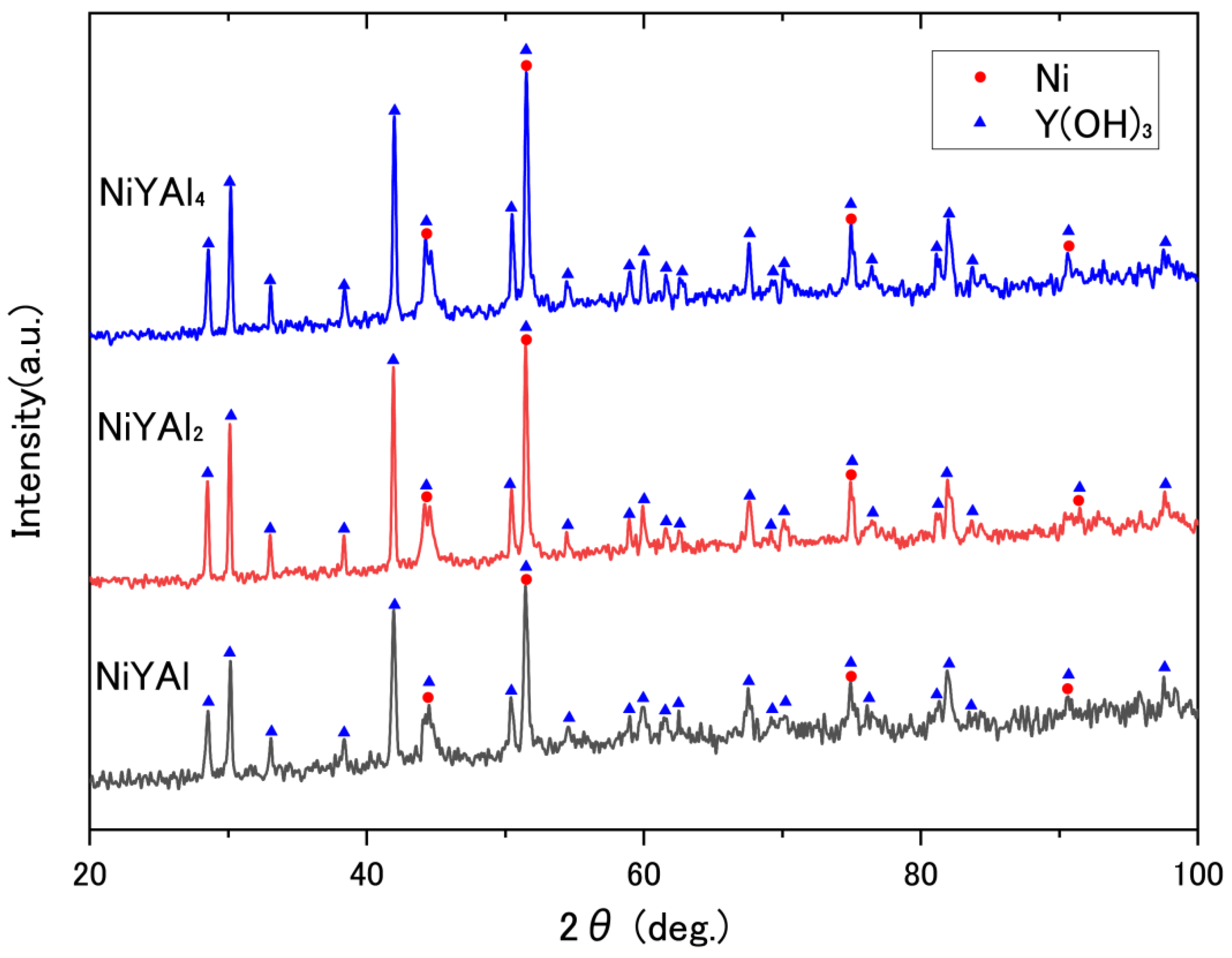
Intermetallic precursors were obtained by arc-melting, and the resulting NiYAl4 (JCPDF#50-1236), NiYAl2 (#76-8082), and NiYAl (#22-0008) compounds were identified in the as-made precursor alloys by XRD, as shown in Figure S1. The subsequent preferential oxidation via the CO + O2 reaction induced the phase separation of Ni, Al2O3 (#04-0877), Y2O3 (#43-0661), and residual intermetallics according to Figure S2. After conducting high-pressure leaching to remove Al components, the resultant products were ultimately converted to Ni and Y(OH)3 (Figure 2); the latter was subsequently converted to Y2O3 through a catalytic reaction in the next step. The conversion from Y(OH)3 to Y2O3 was driven by the DRM reaction as well as heat treatment [13,16].
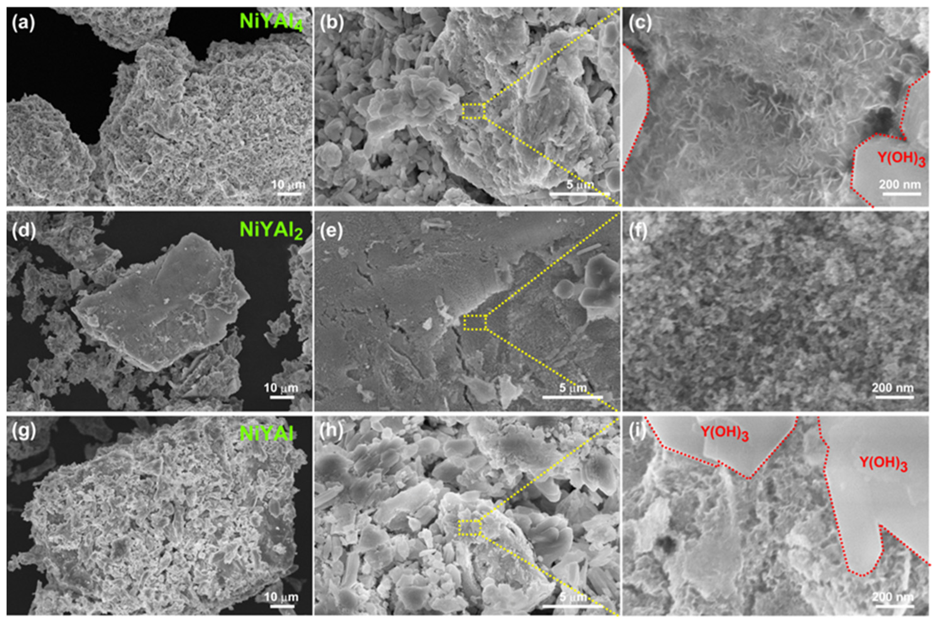
The obtained scanning electron microscope (SEM) images are displayed in Figure 3.
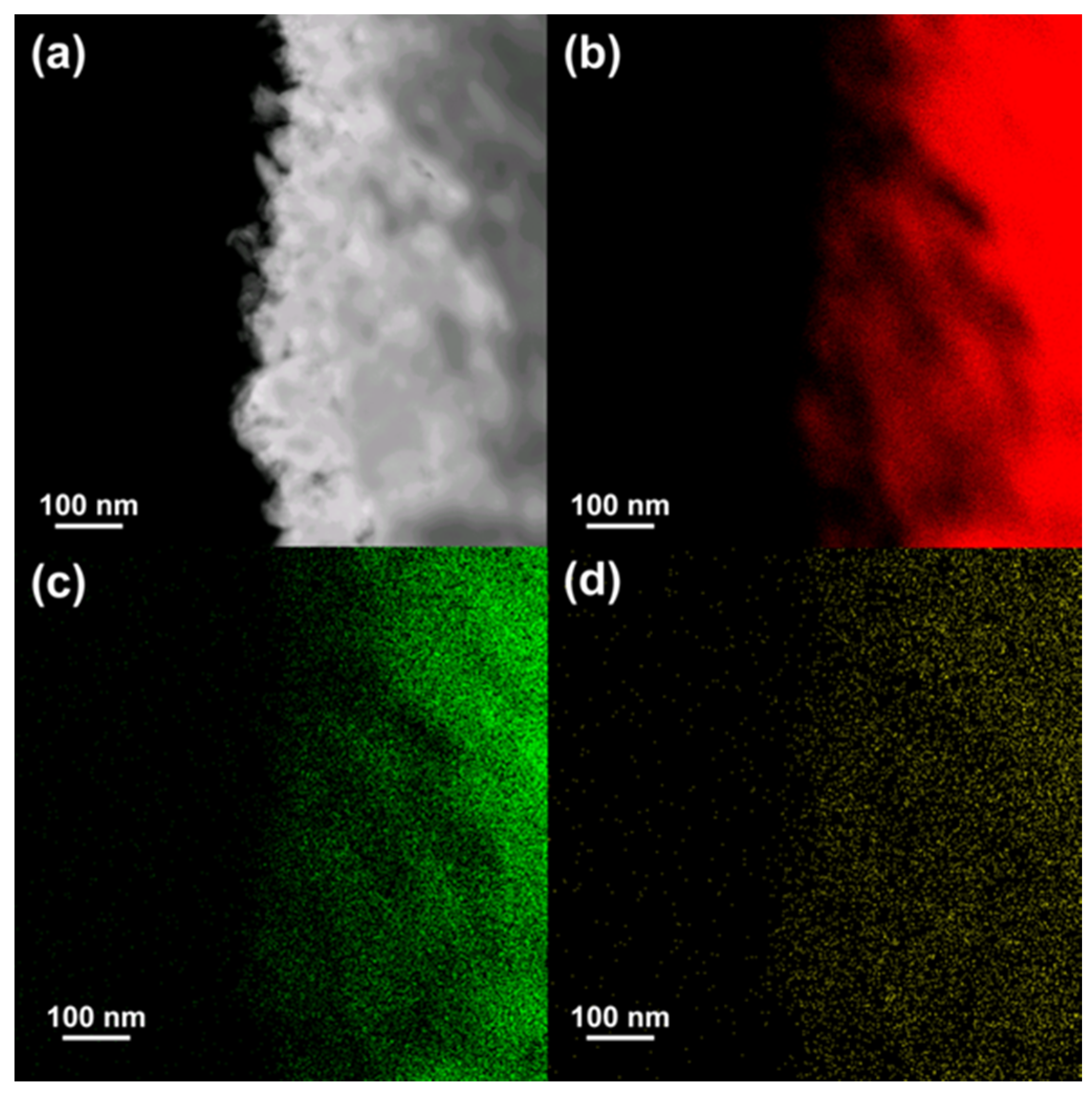
The microstructures of the NiYAl- and NiYAl4-derived samples contain mixed but distinct regions of squarish Y(OH)3 and nanoporous Ni. The microstructure of the NiYAl2-derived catalyst includes the nanoporous Ni and isolated Y(OH)3 regions. The nanoporous Ni region in the NiYAl4-based sample was analyzed by STEM–EDS, as shown in Figure 4.
Its average pore size was approximately 30 nm, while the composition of the nanoporous Ni region in the sample, represented by the formula 91.9Ni–2.6Y–0.5Al–5O (at.%), was relatively uniform.
The catalytic properties of the nanoporous catalysts produced from NiYAl, NiYAl2, and NiYAl4 precursors are summarized in Table 1. Here, the conventional Ni/Al2O3 and Raney Ni catalysts serve as references. The H2/CO ratio is an important indicator of the coking resistance (its ideal value is equal to one, while higher magnitudes of this parameter indicate a significant coking effect). Photographs of the initial and spent catalyst samples are shown in Figure S3. As expected from the increased volume in Figure S3, the spent NiYAl2-derived sample demonstrated the most intense coking effect (H2/CO ratio = 2.4), and the NiYAl4-derived catalyst exhibited the weakest coking effect (H2/CO ratio = 0.7). The XRD analysis (Figure 5a) reveals that the spent samples are composed of Ni and Y2O3 converted from Y(OH)3. In addition, the carbon peaks with the highest intensity appear for the NiYAl2-derived catalyst, whereas the smallest carbon peaks are observed for the NiYAl4-derived one. The NiYAl4-base sample exhibited no catalytic activity after the preferential oxidation (without etching), indicating that the final leaching process was an important step toward achieving the optimal catalyst microstructure. The conventional Ni/Al2O3 and Raney Ni catalysts also demonstrated strong coking effects (their H2/CO ratios were 2.3 and 1.4, respectively). We calculated the carbon balance for these catalysts; carbon balance = {CO formation rate/(CH4 consumption rate + CO2 consumption rate)}, and the results are shown in Figure 5b. The conventional catalyst Ni/Al2O3 exhibits the lowest carbon balance of 0.31. Although Raney Ni shows a relatively higher carbon balance (0.74), the NiYAl4-derived sample represented the optimal carbon balance (0.96) close to the ideal value of 1.0, indicating the optimal DRM pathway. The thermal gravimetric analysis (Figure S4) confirms that the spent NiYAl4-derived sample exhibit the lowest amount of coking.

4. Conclusions

In this study, we fabricated nanoporous catalysts from NiYAlx intermetallic precursors by a combined process of preferential oxidation and leaching. The optimal catalyst obtained from NiYAl4 possessed a structurally robust nanoporous Ni metal and Y oxide structure with high coking resistance for LT-DRM. The described facile fabrication process can be utilized for fabricating highly active catalysts with long-term stability from various binary, ternary, and quaternary metal alloys.

Supplementary Materials

The following are available online at https://www.mdpi.com/1996-1944/13/9/2044/s1, Figure S1: X-ray diffractograms of NiYAl4, NiYAl2, and NiYAl intermetallic precursors, Figure S2: X-ray diffractograms of the NiYAl4, NiYAl2, and NiYAl samples obtained after the preferential oxidation with CO + O2 gas mixture, Figure S3: (left) Photograph of the initial and spent NiYAl-derived catalyst. The degree of carbon coking was estimated from the increase in volume between the initial and spent samples. (right) Photograph of the spent NiYAl-, NiYAl2-, and NiYAl4-derived catalysts. The initial NiYAl2- and NiYAl4-derived samples were similar in appearance to the initial NiYAl-derived catalyst. Figure S4: TG analysis of the spent catalysts derived from NiYAl, NiYAl2, and NiYAl4.

Author Contributions

S.I. fabricated the samples and conducted SEM/XRD characterizations. T.F. performed TEM characterization. X.P. and A.S.B.M.N. performed catalysis tests. T.F. and Z.C. wrote the manuscript. M.M., T.F., and H.A. supervised the entire research project. All authors have read and agreed to the published version of the manuscript.

Funding

This study was mainly funded by the JST-CREST program “Innovative catalysts and creation technologies for the utilization of diverse natural carbon resources”, grant number. JPMJCR15P1 and partially funded by KAKENHI, grant number JP16H02293).

Conflicts of Interest

The authors declare no conflict of interest.

References

  1. Song, Y.; Ozdemir, E.; Ramesh, S.; Adishev, A.; Subramanian, S.; Harale, A.; Albuali, M.; Fadhel, B.A.; Jamal, A.; Moon, D.; et al. Dry reforming of methane by stable Ni-Mo nanocatalysts on single-crystalline MgO. Science 2020, 367, 777–781. [Google Scholar] [CrossRef] [PubMed]
  2. Muraza, O.; Galadima, A. A review on coke management during dry reforming of methane. Int. J. Energy Res. 2015, 39, 1196–1216. [Google Scholar] [CrossRef]
  3. Nair, M.M.; Kaliaguine, S. Structured catalysts for dry reforming of methane. New J. Chem. 2016, 40, 4049–4060. [Google Scholar] [CrossRef]
  4. Lavoie, J.M. Review on dry reforming of methane, a potentially more environmentally-friendly approach to the increasing natural gas exploitation. Front. Chem. 2014, 2, 81. [Google Scholar] [CrossRef] [PubMed] [Green Version]
  5. Kathiraser, Y.; Thisartarn, W.; Sutthiumporn, K.; Kawi, S. Inverse NiAl2O4 on LaAlO3−Al2O3: Unique catalytic structure for stable CO2 reforming of methane. J. Phys. Chem. C 2013, 117, 8120–8130. [Google Scholar] [CrossRef]
  6. Ashok, J.; Bian, Z.; Wang, Z.; Kawi, S. Ni-phyllosilicate structure derived Ni–SiO2–MgO catalysts for bi-reforming applications: Acidity, basicity and thermal stability. Catal. Sci. Technol. 2018, 8, 1730–1742. [Google Scholar] [CrossRef]
  7. Ni, J.; Chen, L.; Lin, J.; Kawi, S. Carbon deposition on borated alumina supported nano-sized Ni catalysts for dry reforming of CH4. Nano Energy 2012, 1, 674–686. [Google Scholar] [CrossRef]
  8. Bian, Z.; Suryawinata, I.Y.; Kawi, S. Highly carbon resistant multicore-shell catalyst derived from Ni-Mg phyllosilicate nanotubes@silica for dry reforming of methane. Appl. Catal. B 2016, 195, 1–8. [Google Scholar] [CrossRef]
  9. Bian, Z.; Kawi, S. Sandwich-like Silica@Ni@Silica multicore–shell catalyst for the low-temperature dry reforming of methane: Confinement effect against carbon formation. ChemCatChem 2018, 10, 320–328. [Google Scholar] [CrossRef]
  10. Shoji, S.; Peng, X.; Imai, T.; Kumar, P.S.M.; Higuchi, K.; Yamamoto, Y.; Tokunaga, T.; Arai, S.; Ueda, S.; Hashimoto, A.; et al. Topologically immobilized catalysis centre for long-term stable carbon dioxide reforming of methane. Chem. Sci. 2019, 10, 3701–3705. [Google Scholar] [CrossRef] [PubMed] [Green Version]
  11. Imai, T.; Ueda, S.; Nagao, S.; Hirata, H.; Deepthi, K.R.; Abe, H. N2O-emission-free exhaust remediation by Rh-NbOx nanocomposites developed from Rh3Nb alloy precursor. RSC Adv. 2017, 7, 9628–9631. [Google Scholar] [CrossRef] [Green Version]
  12. Tanabe, T.; Imai, T.; Tokunaga, T.; Arai, S.; Yamamoto, Y.; Ueda, S.; Ramesh, G.V.; Nagao, S.; Hirata, H.; Matsumoto, S.; et al. Nanophase-separated Ni3Nb as an automobile exhaust catalyst. Chem. Sci. 2017, 8, 3374–3378. [Google Scholar] [CrossRef] [PubMed] [Green Version]
  13. Fujita, T.; Peng, X.; Yamaguchi, A.; Cho, Y.; Zhang, Y.; Higuchi, K.; Yamamoto, Y.; Tokunaga, T.; Arai, S.; Miyauchi, M.; et al. Nanoporous nickel composite catalyst for the dry reforming of methane. ACS Omega 2018, 3, 16651–16657. [Google Scholar] [CrossRef] [PubMed]
  14. Fujita, T.; Abe, H.; Tanabe, T.; Ito, Y.; Tokunaga, T.; Arai, S.; Yamamoto, Y.; Hirata, A.; Chen, M.W. Earth-abundant and durable nanoporous catalyst for exhaust-gas conversion. Adv. Funct. Mater. 2016, 26, 1609–1616. [Google Scholar] [CrossRef]
  15. Huang, J.; Yang, B.; Chen, H.; Wang, H. Thermodynamic optimisation of the Ni-Al-Y ternary system. J. Phase Equilib. Diffus. 2015, 36, 357–365. [Google Scholar] [CrossRef]
  16. Li, Q.; Feng, C.; Jiao, Q.; Guo, L.; Liu, C.; Xu, H.B. Shape-controlled synthesis of yttria nanocrystals under hydrothermal conditions. Phys. Stat. Sol. (a) 2004, 201, 3055–3059. [Google Scholar] [CrossRef]
Figure 1. Schematic illustration of the catalyst preparation from NiYAlx alloys.
Materials 13 02044 g001
Figure 2. X-ray diffractograms of the nanoporous catalysts obtained from NiYAl4, NiYAl2, and NiYAl intermetallic precursors.
Materials 13 02044 g002
Figure 3. SEM images of the nanoporous catalysts derived from (ac) NiYAl4, (df) NiYAl2, and (gi) NiYAl intermetallic precursors.
Materials 13 02044 g003
Figure 4. (a) STEM image and (bd) energy-dispersive x-ray spectroscopy (EDS) chemical maps of the nanoporous Ni region in the NiYAl4-derived sample showing the distributions of Ni (red), Y (green), and O (yellow) elements.
Materials 13 02044 g004
Figure 5. (a) X-ray diffractograms of the spent catalysts prepared from NiYAl4, NiYAl2, and NiYAl intermetallic precursors. The arrow indicates the position of the carbon peak. (b) Carbon balance ratio for the present catalysts and reference catalysts. Carbon balance = {CO formation rate/(CH4 consumption rate + CO2 consumption rate)}.
Materials 13 02044 g005
Table 1. Dry reforming of methane (DRM) parameters of various Ni catalysts including the nanoporous catalysts obtained from NiYAl, NiYAl2, and NiYAl4 intermetallic precursors in this study as well as conventional Ni/Al2O3 and Raney Ni catalysts. The NiYAl4 sample showed no catalytic activity after the preferential oxidation (CO + O2) without leaching.
SampleCH4
Conv.
(%)
CO2
Conv.
(%)
CH4
Consumption Rate
(mmol h−1)
CO2
Consumption Rate
(mmol h−1)
H2
Formation Rate
(mmol h−1)
CO
Formation Rate
(mmol h−1)
H2/CO
Ratio
NiYAl412193.35.15.78.10.7
NiYAl24533128.8188.52.2
NiYAl32298.57.9149.81.4
NiYAl4
(CO + O2)
00-----
Ni/Al2O356371510187.72.3
Raney Ni 33318.98.517131.4
Reaction conditions: 0.1 g; 550 °C; CH4 (10 mL/min), CO2 (10mL/min), and N2 (5 mL/min) with a total flow rate of 25 mL min−1; 4–6 h.