Experimental Investigation of Principal Residual Stress and Fatigue Performance for Turned Nickel-Based Superalloy Inconel 718


Abstract
:1. Introduction
2. Experiments
2.1. Materials and Turning Experiments
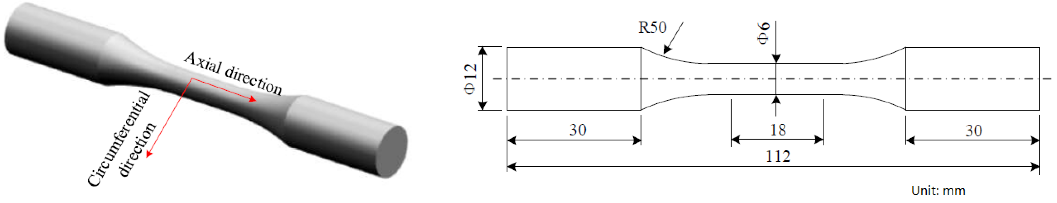
2.2. Fatigue Tests
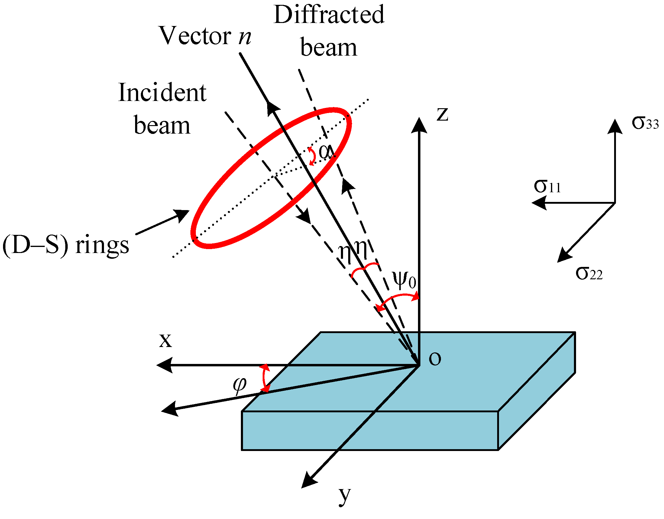
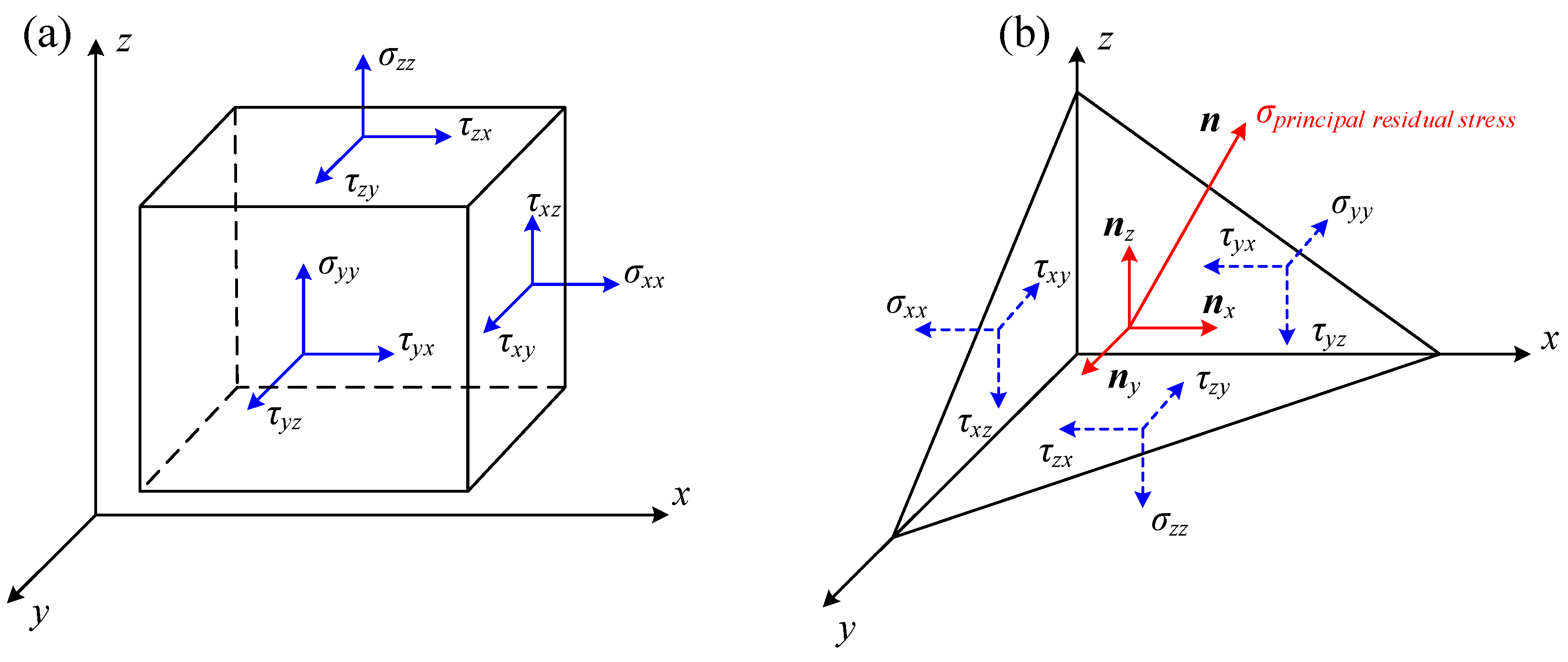
3. Residual Stress Measurements
4. Results and Discussion
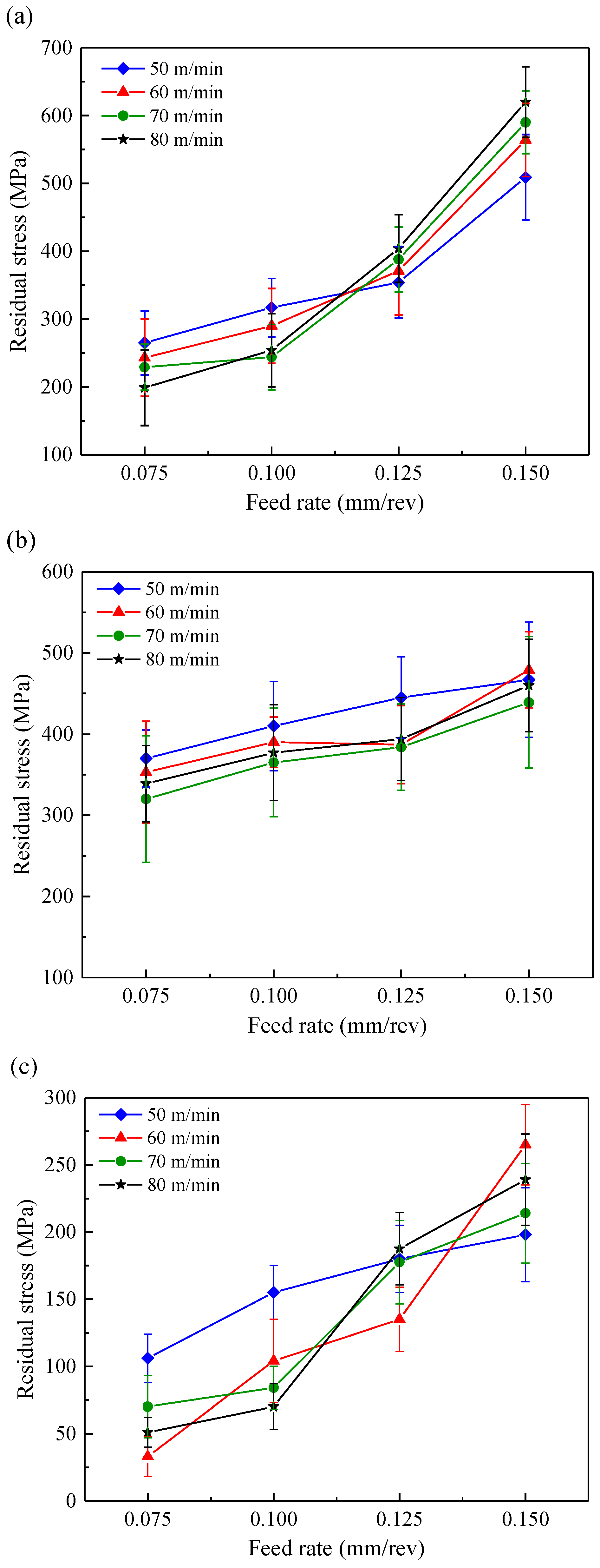
4.1. Surface Residual Stress
4.2. Principal Residual Stress
4.3. Effect of Principal Residual Stress on Fatigue Performance
5. Conclusions
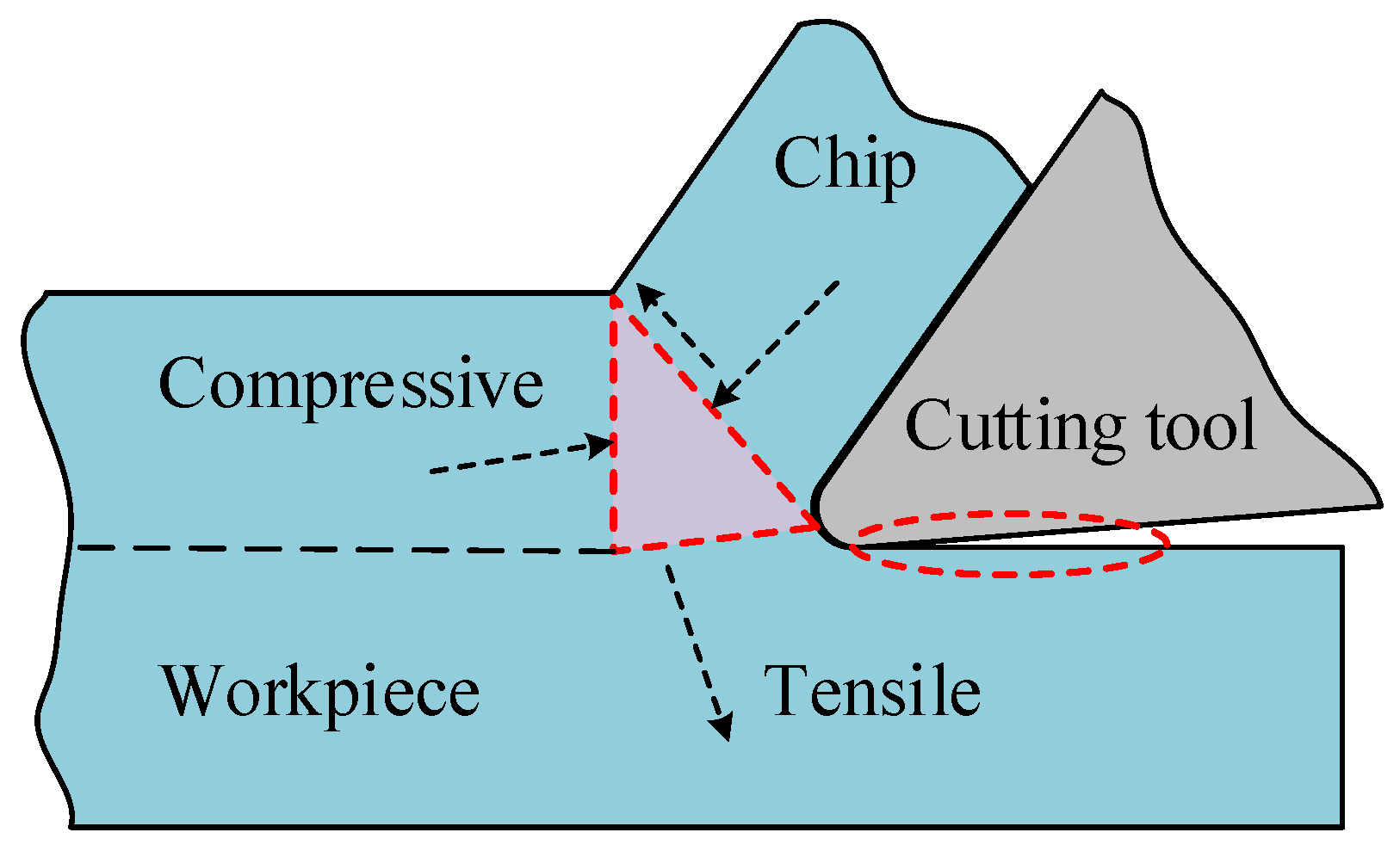
- As the feed rate increases, the surface residual stress tends to be more tensile. The tendency towards more tensile residual stress is related to the larger compressive deformation induced by higher feed rates.
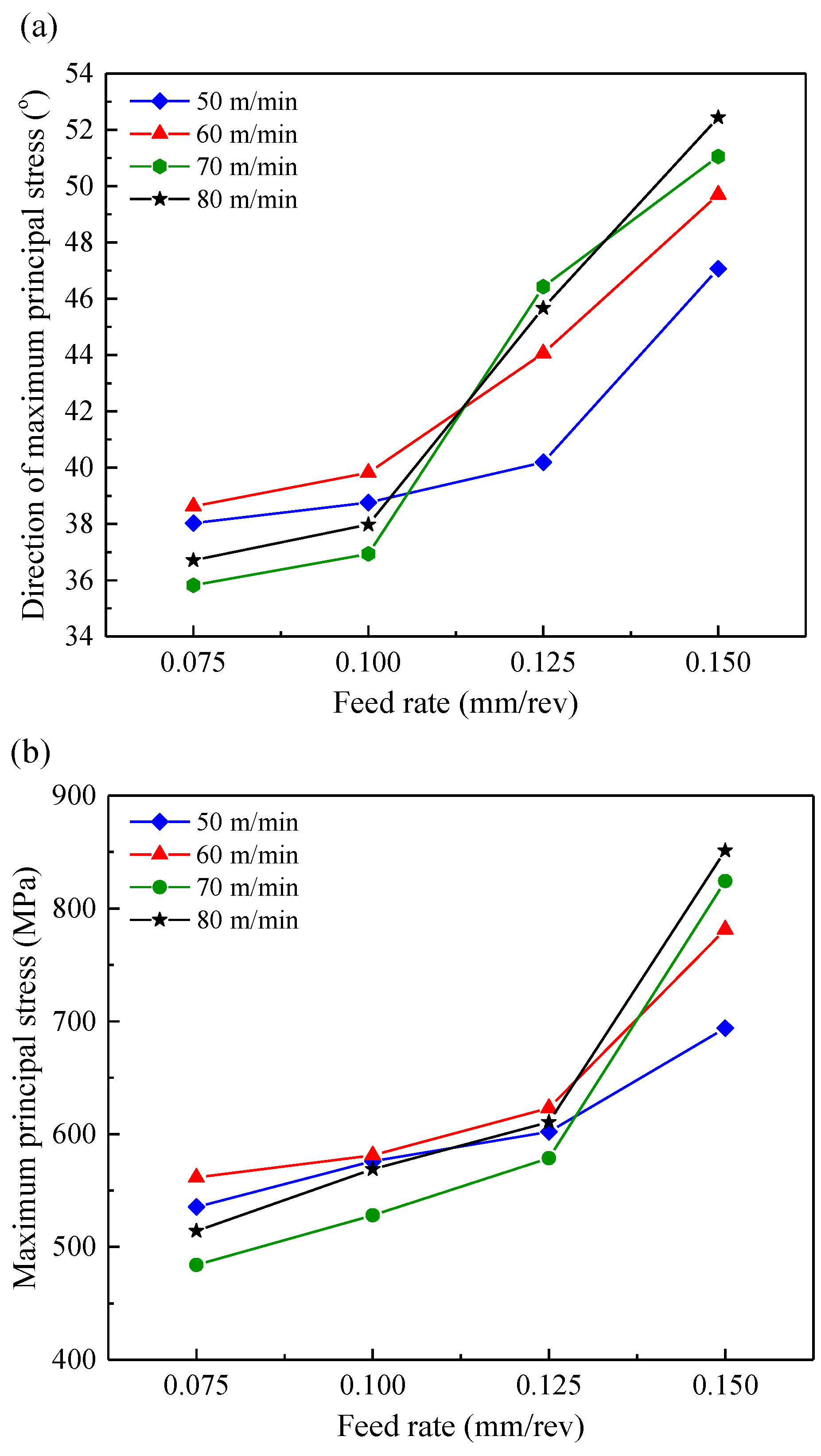
- The maximum principal residual stress direction and magnitude increased significantly with the increase of feed rate. The magnitude of the maximum principal residual stresses was much higher than those of surface residual stresses along the axial and circumferential direction.
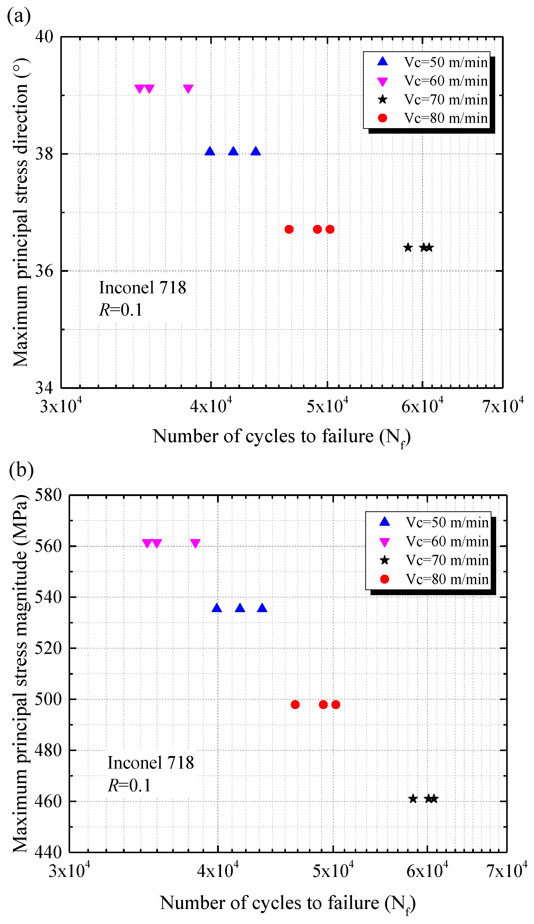
- The direction and magnitude of the maximum principal residual stress tended to be higher, which implied that the direction of the maximum principal residual stress approached the axial direction. The larger total stress in the axial direction was generated, which resulted in lower fatigue life.
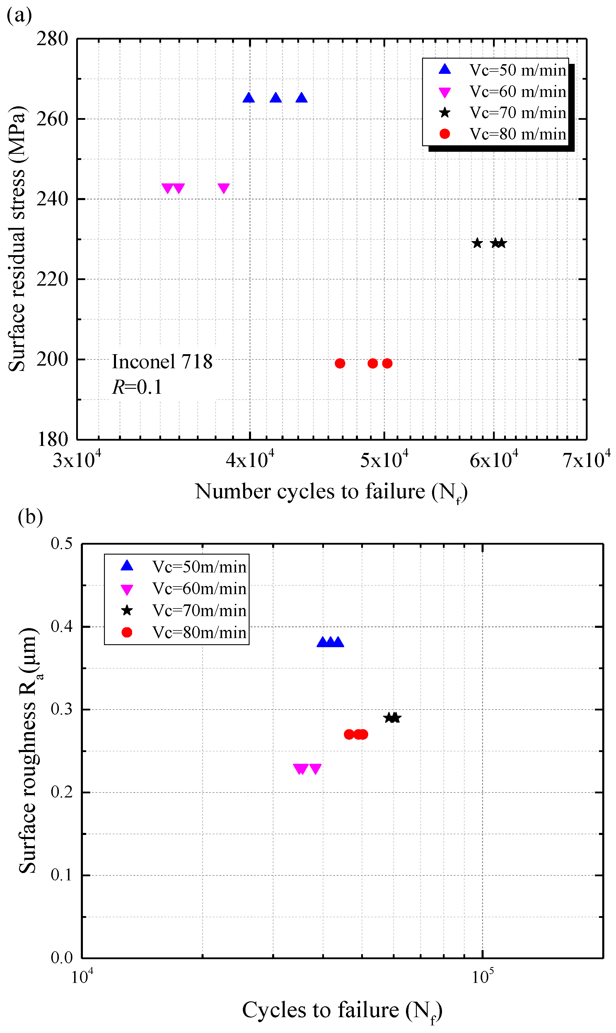
- As the direction of the maximum principal residual stress increased from 36.4° to 39.1° (increased by 7.4%), the fatigue life decreased from 59,765 cycles to 36,236 cycles (decreased by 39.4%). The maximum principal residual stress magnitude diminished by 17.9%, and the fatigue life increased by 83.6%.
- The maximum principal residual stress had a dominant influence on fatigue life compared to that of the surface residual stress along the axial direction. Fatigue tests demonstrated that the surface residual stress appeared to have no influence on fatigue life. The maximum principal residual stress can be considered a prime indicator for evaluation of the residual stress impact on the fatigue performance of machined components.
Author Contributions
Funding
Conflicts of Interest
References
- Kim, H.; Cong, W.L.; Zhang, H.-C.; Liu, Z.C. Laser engineered net shaping of nickel-based superalloy Inconel 718 powders onto AISI 4140 alloy steel substrates: Interface bond and fracture failure mechanism. Materials 2017, 10, 341. [Google Scholar] [CrossRef] [PubMed]
- Ulutan, D.; Ozel, T. Machining induced surface integrity in titanium and nickel alloys: A review. Int. J. Mach. Tools Manuf. 2011, 51, 250–280. [Google Scholar] [CrossRef]
- Zhu, L.; Wu, Z.R.; Hu, X.T.; Song, Y.D. Investigation of small fatigue crack initiation and growth behavior of nickel base superalloy GH4169. Fatigue Fract. Eng. Mater. Struct. 2016, 39, 1150–1160. [Google Scholar] [CrossRef]
- Galatolo, R.; Fanteria, D. Influence of turning parameters on the high-temperature fatigue performance of Inconel 718 superalloy. Fatigue Fract. Eng. Mater. Struct. 2017, 40, 2019–2031. [Google Scholar] [CrossRef]
- Novovic, D.; Dewes, R.C.; Aspinwall, D.K.; Voice, W.; Bowen, P. The effect of machined topography and integrity on fatigue life. Int. J. Mach. Tools Manuf. 2004, 44, 125–134. [Google Scholar] [CrossRef]
- Javidi, A.; Rieger, U.; Eichlseder, W. The effect of machining on the surface integrity and fatigue life. Int. J. Fatigue 2008, 30, 2050–2055. [Google Scholar] [CrossRef]
- Thakur, A.; Gangopadhyay, S. State-of-the-art in surface integrity in machining of nickel-based super alloys. Int. J. Mach. Tools Manuf. 2016, 100, 25–54. [Google Scholar] [CrossRef]
- McClung, R.C. A literature survey on the stability and significance of residual stresses during fatigue. Fatigue Fract. Eng. Mater. Struct. 2007, 30, 173–205. [Google Scholar] [CrossRef]
- Foss, B.J.; Gray, S.; Hardy, M.C.; Stekovic, S.; McPhail, D.S.; Shollock, B.A. Analysis of shot-peening and residual stress relaxation in the nickel-based superalloy RR1000. Acta Mater. 2013, 61, 2548–2559. [Google Scholar] [CrossRef]
- Herbert, C.; Axinte, D.A.; Hardy, M.; Withers, P. Influence of surface anomalies following hole making operations on the fatigue performance for a nickel-based superalloy. ASME J. Manuf. Sci. Eng. 2014, 136, 101601–101609. [Google Scholar] [CrossRef]
- Ren, X.D.; Zhan, Q.B.; Yang, H.M.; Dai, F.Z.; Cui, C.Y.; Sun, G.F.; Ruan, L. The effects of residual stress on fatigue behavior and crack propagation from laser shock processing-worked hole. Mater. Des. 2013, 44, 149–154. [Google Scholar] [CrossRef]
- Scuracchio, B.G.; de Lima, N.B.; Schön, C.G. Role of residual stresses induced by double peening on fatigue durability of automotive leaf springs. Mater. Des. 2013, 47, 672–676. [Google Scholar] [CrossRef]
- Schwach, D.W.; Guo, Y.B. A fundamental study on the impact of surface integrity by hard turning on rolling contact fatigue. Int. J. Fatigue 2006, 28, 1838–1844. [Google Scholar] [CrossRef]
- Doremus, L.; Cormier, J.; Villechaise, P.; Henaff, G.; Nadot, Y.; Pierret, S. Influence of residual stresses on the fatigue crack growth from surface anomalies in a nickel-based superalloy. Mater. Sci. Eng. A 2015, 644, 234–246. [Google Scholar] [CrossRef]
- Pawade, R.S.; Joshi, S.S.; Brahmankar, P.K. Effect of machining parameters and cutting edge geometry on surface integrity of high-speed turned Inconel 718. Int. J. Mach. Tools Manuf. 2008, 48, 15–28. [Google Scholar] [CrossRef]
- Arrazola, P.J.; Kortabarria, A.; Madariaga, A.; Esnaola, J.A.; Fernandez, E.; Cappellini, C.; Ulutan, D.; Özel, T. On the machining induced residual stresses in IN718 nickel-based alloy: Experiments and predictions with finite element simulation. Simul. Model. Pract. Theory 2014, 41, 87–103. [Google Scholar] [CrossRef]
- Madariaga, A.; Esnaola, J.A.; Fernandez, E.; Arrazola, P.J.; Garay, A.; Morel, F. Analysis of residual stress and work-hardened profiles on Inconel 718 when face turning with large-nose radius tools. Int. J. Adv. Manuf. Technol. 2014, 71, 1587–1598. [Google Scholar] [CrossRef]
- Berruti, T.; Lavella, M.; Gola, M.M. Residual stresses on Inconel 718 turbine shaft samples after turning. Mach. Sci. Technol. 2009, 13, 543–560. [Google Scholar] [CrossRef]
- Coto, B.; Navas, V.G.; Gonzalo, O.; Aranzabe, A.; Sanz, C. Influences of turning parameters in surface residual stresses in AISI 4340 steel. Int. J. Adv. Manuf. Technol. 2011, 53, 911–919. [Google Scholar] [CrossRef]
- Navas, V.G.; Gonzalo, O.; Bengoetxea, I. Effect of cutting parameters in the surface residual stresses generated by turning in AISI 4340 steel. Int. J. Mach. Tools Manuf. 2012, 61, 48–57. [Google Scholar] [CrossRef]
- Hua, Y.; Liu, Z. Effects of cutting parameters and tool nose radius on surface roughness and work hardening during dry turning Inconel 718. Int. J. Adv. Manuf. Technol. 2018, 96, 2421–2430. [Google Scholar] [CrossRef]
- Moussaoui, K.; Mousseigne, M.; Senatore, J.; Chieragatti, R.; Lamesle, P. The effect of roughness and residual stresses on fatigue life time of an alloy of titanium. Int. J. Adv. Manuf. Technol. 2015, 78, 557–563. [Google Scholar] [CrossRef]
- Moussaoui, K.; Mousseigne, M.; Senatore, J.; Chieragatti, R.; Lamesle, P. Influence of milling on the fatigue lifetime of a Ti6Al4V titanium alloy. Metals 2015, 5, 1148–1162. [Google Scholar] [CrossRef]
- Sharman, A.R.C.; Hughes, J.I.; Ridgway, K. Workpiece surface integrity and tool life issues when turning Inconel 718TM nickel based superalloy. Mach. Sci. Technol. 2004, 8, 399–414. [Google Scholar] [CrossRef]
- Thakur, D.G.; Ramamoorthy, B.; Vijayaraghavan, L. Effect of cutting parameters on the degree of work hardening and tool life during high-speed machining of Inconel 718. Int. J. Adv. Manuf. Technol. 2012, 59, 483–489. [Google Scholar] [CrossRef]
- Taira, S.; Tanaka, K.; Yamasaki, T. A method of X-ray microbeam measurement of local stress and its application to fatigue crack growth problems. J. Mater. Sci. Japan 1987, 27, 251–256. [Google Scholar] [CrossRef]
- Lu, J. Handbook of Measurement of Residual Stresses; The Fairmont Press: Lilburn, GA, USA, 1996; ISBN 978-0132557382. [Google Scholar]
- Noyan, I.C.; Cohen, J.B. Residual Stress Measurement by Diffraction and Interpretation; Springer: New York, NY, USA, 1987; ISBN 978-1461395713. [Google Scholar]
- Sharman, A.R.C.; Hughes, J.I.; Ridgway, K. The effect of tool nose radius on surface integrity and residual stresses when turning Inconel 718™. J. Mater. Process. Technol. 2015, 216, 123–132. [Google Scholar] [CrossRef]
- Suresh, S. Fatigue of Materials; Cambridge University Press: Cambridge, UK, 1998; ISBN 978-0521578479. [Google Scholar]


| Element | Fe | Cr | Nb | Mo | Ti | Al | Co | Ni |
|---|---|---|---|---|---|---|---|---|
| wt % | 18.19 | 18.05 | 5.43 | 2.98 | 1.02 | 0.50 | 0.31 | Balance |
| Work Temperature (°C) | Tensile Strength σb (MPa) | Yield Strength σ0.2 (MPa) | Elongation (%) | Shrinkage (%) | Hardness (HBW) |
|---|---|---|---|---|---|
| 20 | 1502 | 1360.5 | 19.3 | 34.5 | 439 |
| Temperature (°C) | 300 | 400 | 500 | 600 | 700 | 800 |
|---|---|---|---|---|---|---|
| Specific heat capacity (J/(kg·°C)) | 481.4 | 493.9 | 514.8 | 539.0 | 573.4 | 615.3 |
| Parameters | Cutting Speed (m/min) | Feed Rate (mm/rev) | Nose Radius (mm) | Depth of Cut (mm) |
|---|---|---|---|---|
| Levels | 50, 60, 70, 80 | 0.075, 0.10, 0.125, 0.15 | 0.8 | 0.2 |
© 2018 by the authors. Licensee MDPI, Basel, Switzerland. This article is an open access article distributed under the terms and conditions of the Creative Commons Attribution (CC BY) license (http://creativecommons.org/licenses/by/4.0/).
Share and Cite
Hua, Y.; Liu, Z. Experimental Investigation of Principal Residual Stress and Fatigue Performance for Turned Nickel-Based Superalloy Inconel 718. Materials 2018, 11, 879. https://doi.org/10.3390/ma11060879
Hua Y, Liu Z. Experimental Investigation of Principal Residual Stress and Fatigue Performance for Turned Nickel-Based Superalloy Inconel 718. Materials. 2018; 11(6):879. https://doi.org/10.3390/ma11060879
Chicago/Turabian StyleHua, Yang, and Zhanqiang Liu. 2018. "Experimental Investigation of Principal Residual Stress and Fatigue Performance for Turned Nickel-Based Superalloy Inconel 718" Materials 11, no. 6: 879. https://doi.org/10.3390/ma11060879
APA StyleHua, Y., & Liu, Z. (2018). Experimental Investigation of Principal Residual Stress and Fatigue Performance for Turned Nickel-Based Superalloy Inconel 718. Materials, 11(6), 879. https://doi.org/10.3390/ma11060879