Abstract
The stainless steel bipolar plate has received much attention due to the cost of graphite bipolar plates. Since the micro-channel of bipolar plates plays the role of fuel flow field, electric connector and fuel sealing, an investigation of the deep drawing process for stainless steel micro-channel arrays is reported in this work. The updated Lagrangian formulation, degenerated shell finite element analysis, and the r-minimum rule have been employed to study the relationship between punch load and stroke, distributions of stress and strain, thickness variations and depth variations of individual micro-channel sections. A micro-channel array is practically formed, with a width and depth of a single micro-channel of 0.75 mm and 0.5 mm, respectively. Fractures were usually observed in the fillet corner of the micro-channel bottom. According to the experimental results, more attention should be devoted to the fillet dimension design of punch and die. A larger die fillet can lead to better formability and a reduction of the punch load. In addition, the micro-channel thickness and the fillet radius have to be taken into consideration at the same time. Finally, the punch load estimated by the unmodified metal forming equation is higher than that of experiments.
1. Introduction
Fuel cells are composed of several single-cells, which are serially connected with bipolar plates to generate sufficient current and voltage. Bipolar plates play the role of fuel input channel as well as of an electric bridge for reducing contact resistance or impedance when being connected with conducting wires [1,2,3]. Bipolar plates therefore become the key to miniaturizing the full cell, where bipolar plates represent more than 80% by weight and 40% by cost of the fuel cell [4,5]. In addition, both of the power generation efficiency and the manufacturing cost are determined by this component as well. In this case, the efficiency of heat radiating and electric conduction, which are highly related to the design of flow field, materials, and manufacturing methods of bipolar plates, should be taken into account [6,7]. Graphite and metallic materials are currently the most popular materials for bipolar plates. A composite bipolar plate made of the graphite/phenol formaldehyde resin was introduced for fuel cell applications [8]. The interaction between electrical conductivity, the shape factor and the orientation factor has been investigated. However, for reducing processing difficulty and manufacturing cost, metallic materials have received much more attention than graphite now [9,10]. The performance and long-term stability of bipolar plates made from Ti metal and stainless steels have been revealed by Park et al. [11]. The performance of Ti is lower than that of stainless steel due to the decrease in ohmic loss regions. On the other hand, stainless steels perform better as bipolar plates with regard to cell performance, cell resistance and durability. In order to produce channels for delivering fuel on metal sheets as well as reducing costs, numerous metal forming processes have been proposed such as stamping, drawing, and hydraulic pressure [10,12,13,14]. A metal bipolar plate manufactured by stamping is regarded as an alternative to the graphite bipolar plate [15]. However, the errors of micro-channel dimensions by stamping are definitely encountered, and lead to performance loss. An investigation into bipolar plate structural parameters has been carried out by Imanmehr and Pourmahmod [16]. According to the analysis results, the parameters of micro-channels have a great impact on outlet voltage at high current densities. For increasing the contact area of gas, the flow channel number should be increased as much as possible [14]. However, these micro-channels can hardly be machined by conventional methods due to their dimensions. The effect of micro-channel width on fuel cell performance has been studied [17]. The best overall performance is from the narrowest channel width, and a computational fluid dynamics model was developed to study performance variation against channel width. Similar researches regarding the effects of channel dimensions were also reported [3,13,18]. As mentioned above, the stainless steel becomes one of the most popular materials for bipolar plates due to the cost, the power generation performance, and the corrosion resistance. Though the performance of anti-corrosion for stainless steel is fine, the high strain hardening exponent of this material leads to difficulty in manufacturing. Since the micro-channel plays an important role in chemical reaction performance, such as the gas reaction area and the transport channel of solution and electron, a study regarding the deep drawing of micro-channel arrays for stainless steel sheets has been accomplished in this work. The differences between macro and micro effects are studied as well. The purpose of this work is to discuss the parameters of deep drawing process for metallic micro-channels.
2. Basic Theory
2.1. Stiffness Equation
The Lagrangian formulation can be employed to explain the properties of plastic flow. According to the Lagrangian formulation the rate equation for virtual work is as follows [19]:
where vi is the velocity, the rate of nominal traction is ti, and V and Sf are referred to the material volume and the surface respectively. Since both the virtual work rate equation and the constitutive relation are linear, they can be replaced with increments defined with respect to any monotonously increasing measures, such as the increase in the displacement of the tool. The complete global stiffness matrix can be stated as follows:
in which:
The term in Equation (2) is the increment of nodal displacement and the increase of nodal force is . [K] and [Cep] indicate the global tangent stiffness matrix and the elemental elastic-plastic constitutive matrix, respectively. The strain rate velocity matrix and the velocity gradient matrix are [B] and [E] respectively. [Q] and [Z] correspond to the stress correction matrices against each deformation stage respectively.
2.2. Selective Reduced Integration Formulation
The plastic medium volume is incompressible. Therefore, over-strong constraint for thin plates will be engaged when the full integration technique is applied for finite elements. This situation is due to the setting of no shear strain γxz and γyz during the deformation [20]. For solving such problems, in which the volumetrically in stiff contribution is involved, the selective reduced integration has been verified as an effective method [21]. The generalized formulation of selective reduced integration proposed by Hughes [22] has been employed in this work. In addition, the four-node quadrilateral degenerated shell element [23] is utilized in the intensive analysis.
2.3. Scale Factors for Micro-Forming Process of Sheet Metal
Generally, the size effect can be neglected for the thickness of sheet metal within 1.0 mm. However, the metallic sheet thickness in micro-forming process is of micron range and the traditional material model is therefore no longer suitable for analyses under this condition. A modified model without considering size effect has been employed in this work. A traditional material model can be defined as follows:
The thickness of the metallic sheet in the following analysis is 50 μm. As a result, the size effect should be taken into account for the amendment of stress-strain relations. Consequently, Equation (4) is further amended as follows:
where a, b, c, d are the correction coefficients. t is the metallic sheet thickness. These correction coefficients can be given according to Ref. [24] and Equation (5) therefore becomes
Both the traditional material model, Equation (4), and the modified material model, Equation (6), are enclosed in the following finite element analyses. Experiments are conducted for the performance verification of these two models.
3. Numerical Analysis for Micro-Channel Array Forming Process
Four-node quadrilateral degenerated shell elements are utilized in this work for deriving the stiffness matrix, and Finite Element Analysis (FEA) [25] is employed for the pre-processing and post-processing. Since the die and stainless steel plates are supposed to be symmetric, the simulation is performed against a 1/4 figure to effectively reduce the analysis time for arithmetic processing. The die and the metallic plate are then meshed with quadrilateral elements. These meshed data are transformed to the 3D elastic-plastic FEA program for the following simulation analysis.
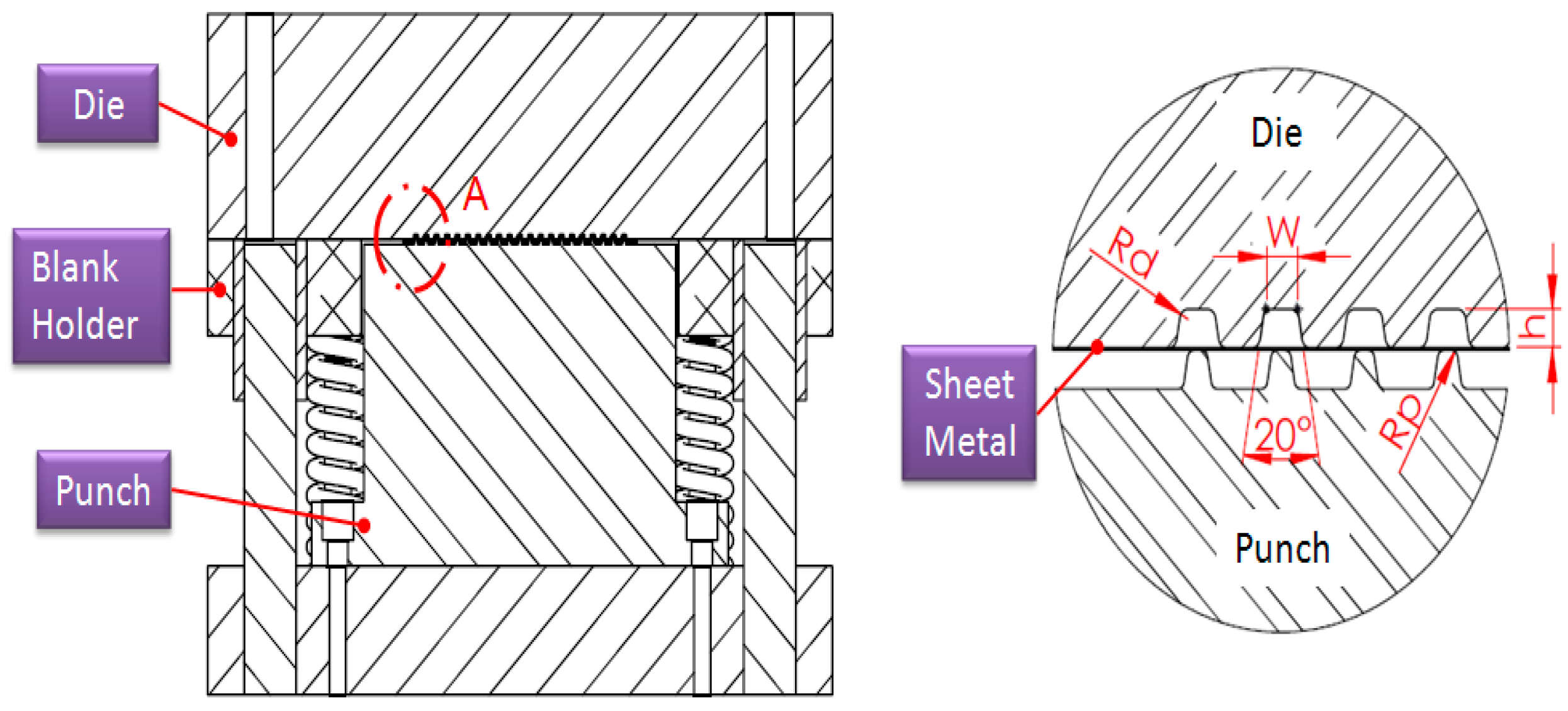
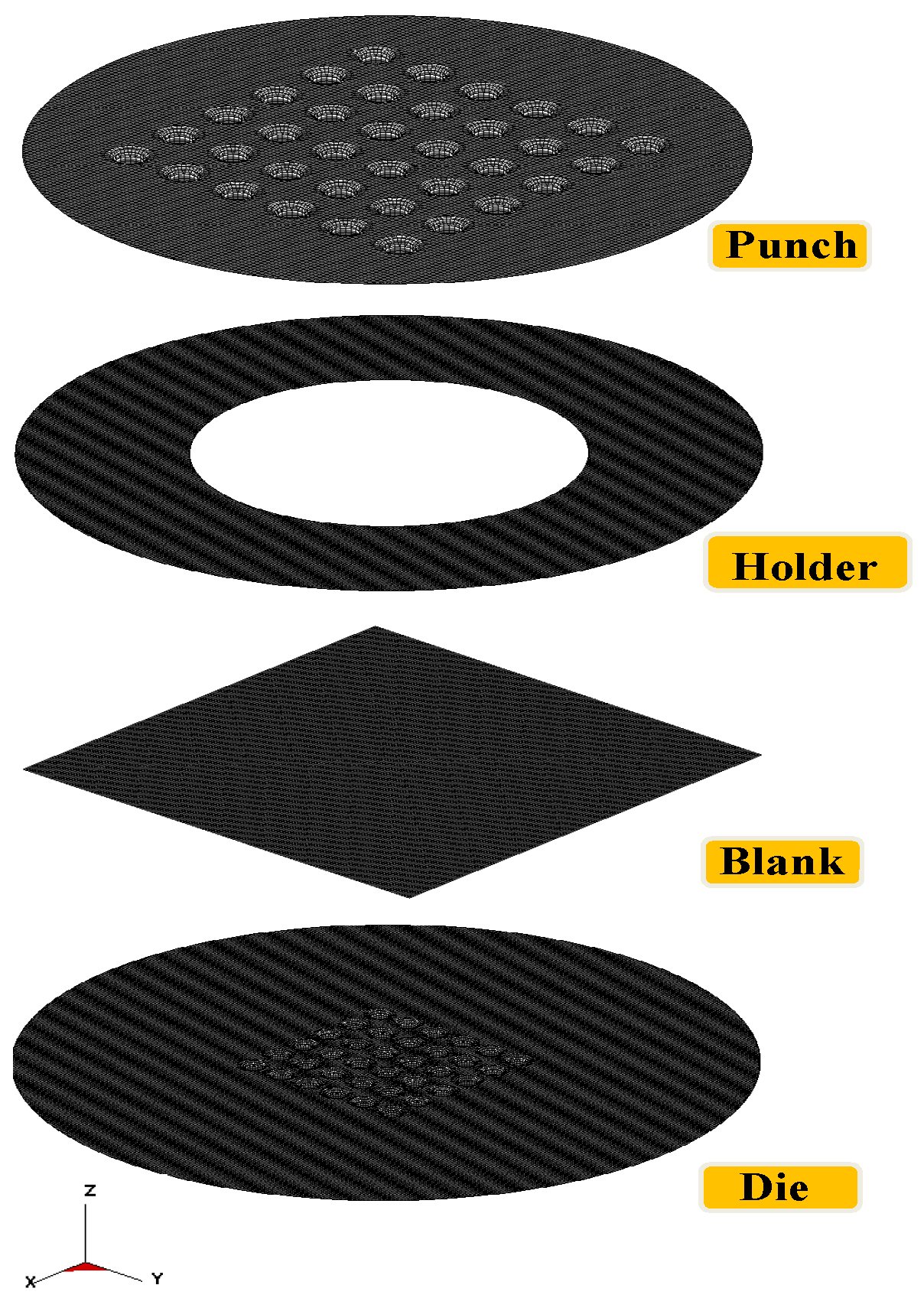
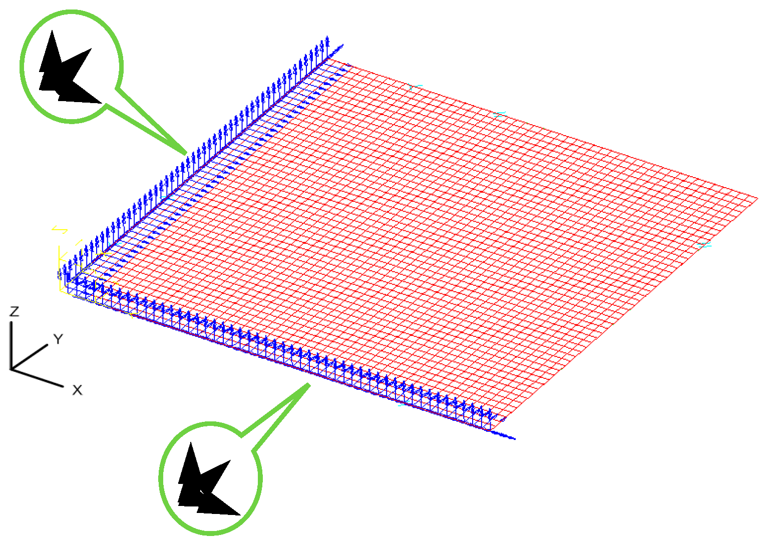
Since the die is too small to be manufactured by conventional methods, electric discharge machining is utilized for the die fabrication. The micro-channel array forming process is illustrated in Figure 1. The dimensions of tools for the micro-channel array forming process are listed in Table 1, where the die gap is set to be 1.1 times the plate thickness, in accordance with traditional empirical rules. Since the thickness of the stainless steel sheet used in this study is 0.05 mm, the die gap is designed to be 0.055 mm. The mechanical properties of the stainless steel sheet is illustrated in Table 2. The die and the metallic plate are meshed into quadrilateral elements (see Figure 2). These meshed data are then loaded into the 3D elastic-plastic FEA program for the following numerical analysis. Figure 3 is the cross-section schematic diagram of the processed plate. L1 and L2 sections are the main objects for the following investigation, including the thickness distribution and the contour. In the micro-channel array deep drawing process, the die will directly contact the blank surface. That means the node for die contact and separation should be defined. Nodes are therefore divided into two categries: contact node and free node. The boundary conditions of the material meshing quadrilateral elements are demostrated in Figure 4.

Figure 1.
Micro-channel array forming process for stainless steel plates.

Table 1.
Dimensions of tools.
Table 2.
Mechanical properties of stainless steel SUS304.

Figure 2.
Finite element model.
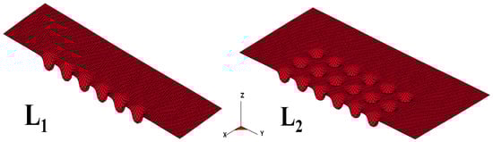
Figure 3.
Measurement schematic diagram.

Figure 4.
Boundary conditions of blank.
4. Experimental Results and Discussion
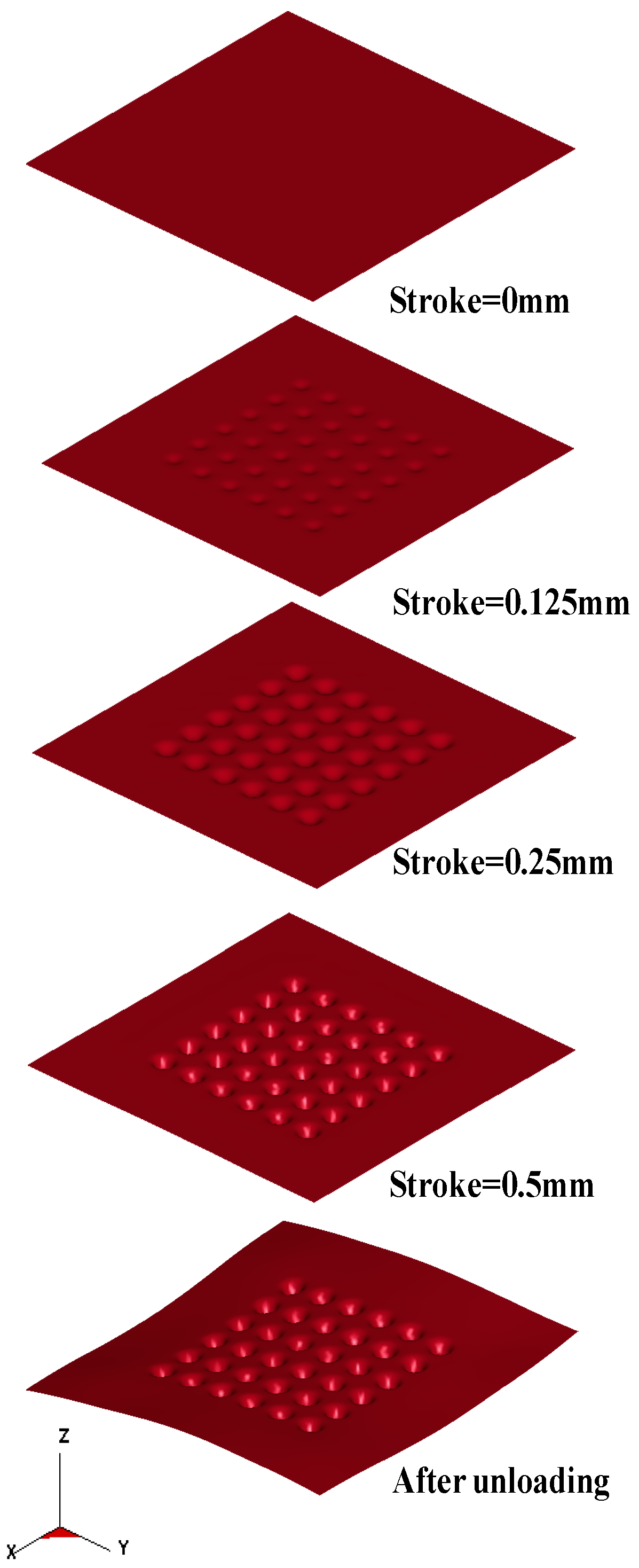
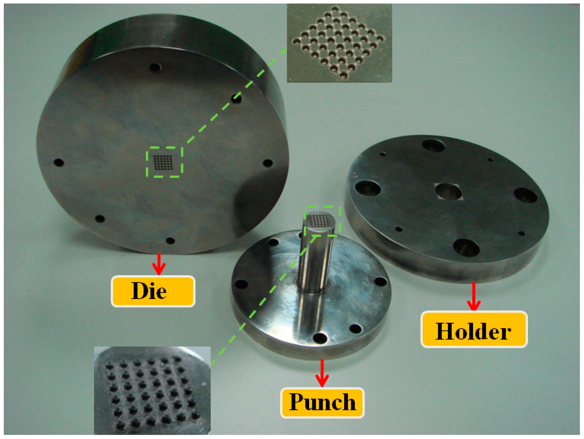
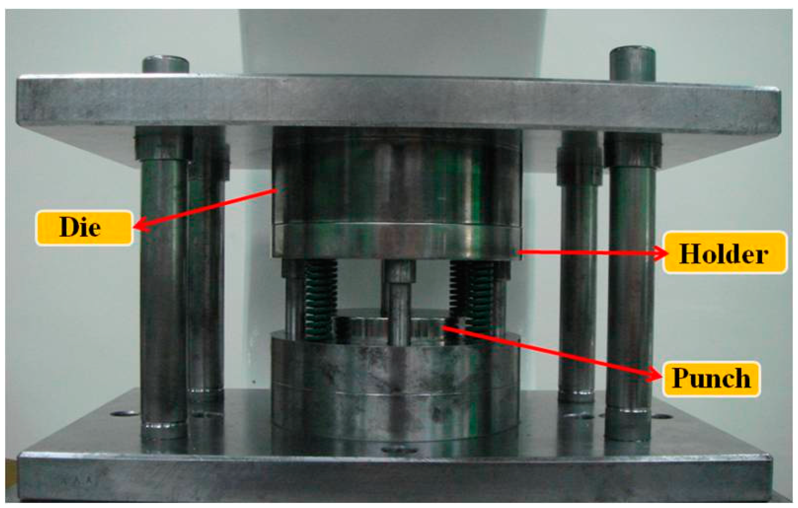
The micro-channel array deep drawing process for stainless steel plate is shown in Figure 5. In total, there are five steps in this geometric deformation process. The plate is gradually deformed during micro-channel forming until the unloading state. Throughout the entire micro-channel forming process, the contact, separation, and friction conditions can be accurately estimated by the r-minimum (rmin) rule. The rmin rule is mainly for the definition of boundary conditions for degenerated four-node shell elements during deformation analyses. Figure 6 is the prototype of tools employed in the micro-channel array drawing experiment, including punch, die bottom, and blank holder. The test rig and the electro press (JANOME JP-5004, JANOME Sewing Machines Co., Ltd., Tokyo, Japan) for micro-channel array forming process are shown in Figure 7 and Figure 8 respectively.

Figure 5.
The geometric deformation of thin metal sheet against various strokes.
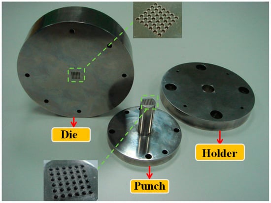
Figure 6.
The prototype of tools for the micro-channel array forming process.

Figure 7.
The test rig for the micro-channel array forming process.
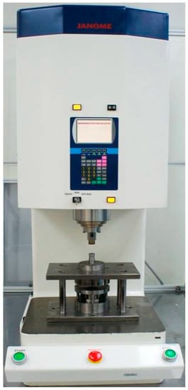
Figure 8.
The electro press for the micro-channel array forming process (JANOME JP-5004).
4.1. Comparisons between Experimental Results and Simulation Results
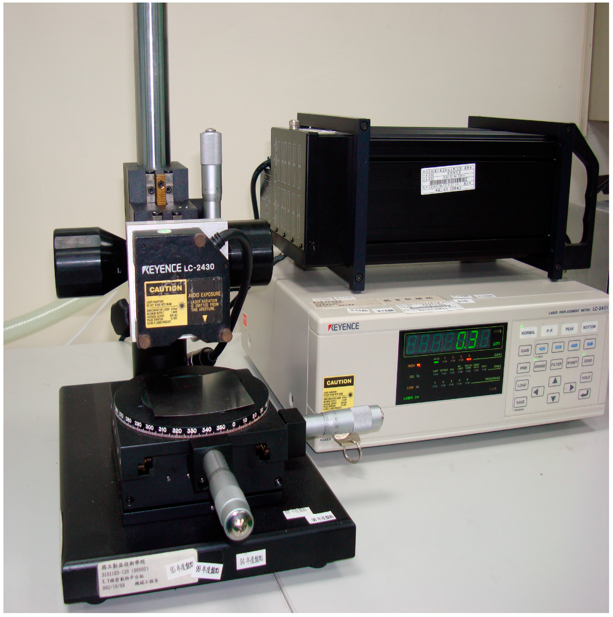
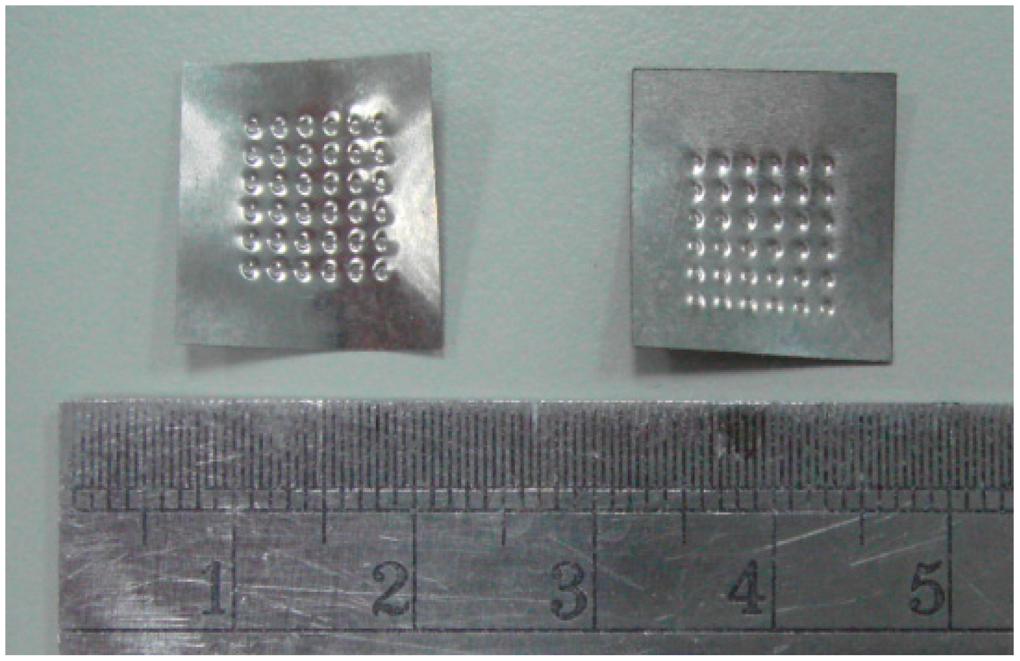
Two models, i.e., macro and micro, are employed in the simulation of the micro-channel array deep drawing process for stainless steel plate. Since the thickness of the stainless steel plate for experiments is merely 50 μm, the contour measurements of the finished workpieces is accomplished by using a laser displacement system, as shown in Figure 9 (Keyence LC-2430, Osaka, Japan). Some of the processed workpieces are shown in Figure 10.

Figure 9.
Laser displacement system (Keyence LC-2430) for contour measurements of stamped stainless steel plates.

Figure 10.
Processed workpiece of micro-channel array forming process.
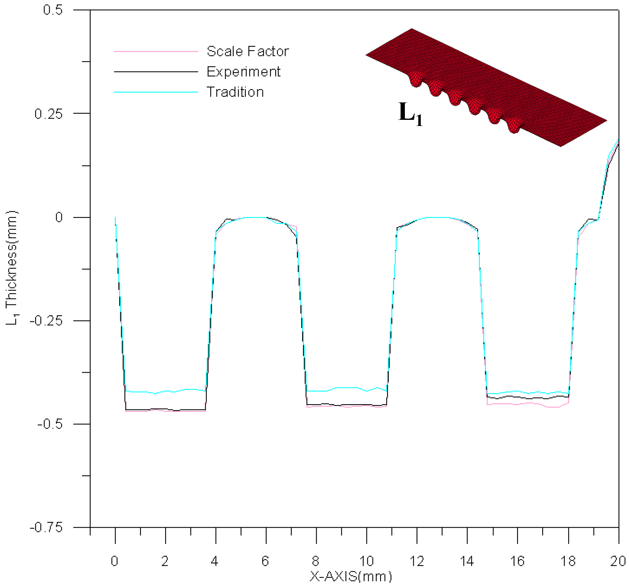
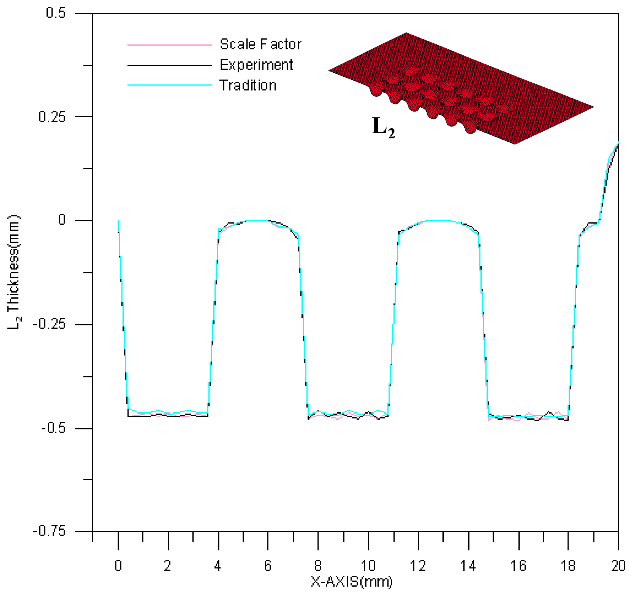
Figure 11 is a comparison between theoretical estimations and experimental results for the L1 section contour. The channel depth is about 0.5 mm. However, the effect of material springback results in an upward curl of the peripheral part of the stainless steel plate. Namely, the channel will deviate from the center of stainless steel plate and move downward. As a result, the deformation trend could be predicted more precisely by the material model of modified scale factor than by traditional material models. A comparison between theoretical estimations and experimental results for the L2 section contour is shown in Figure 12. Similarly, the difference in channel depth between these three results (experimental results, traditional material model and modified scale-factor material model) is mainly due to the peripheral curvature of the stainless steel plate. The maximum depth error between these two material models is about 0.035 mm. The performance of the modified scale factor material model is still better than that of traditional material model for L2 section contour estimation.
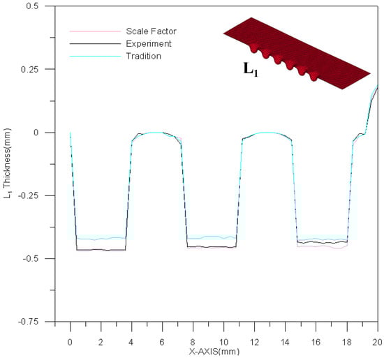
Figure 11.
The contour comparison of L1 section.
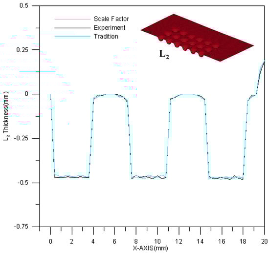
Figure 12.
The contour comparison of L2 section.
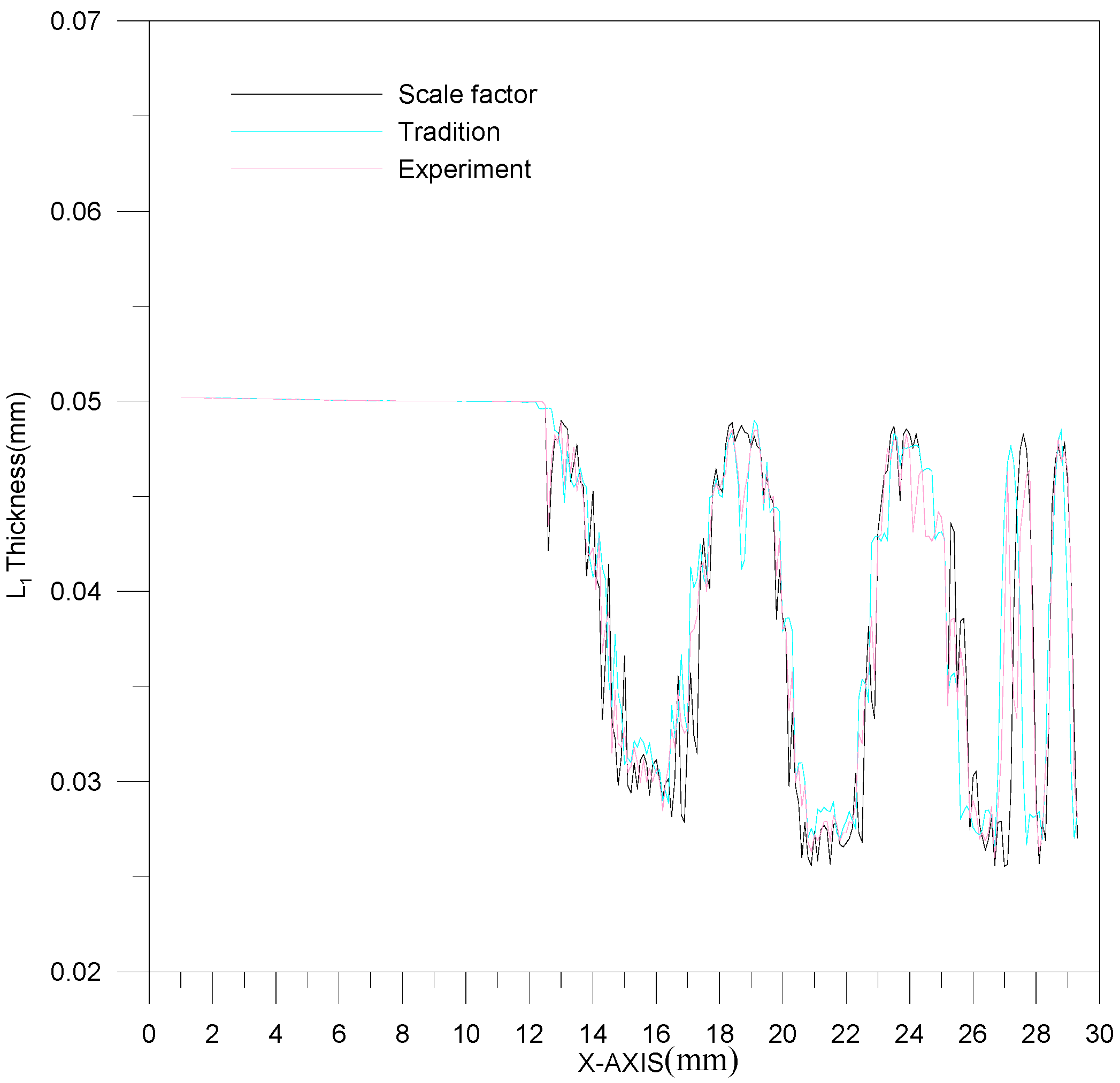
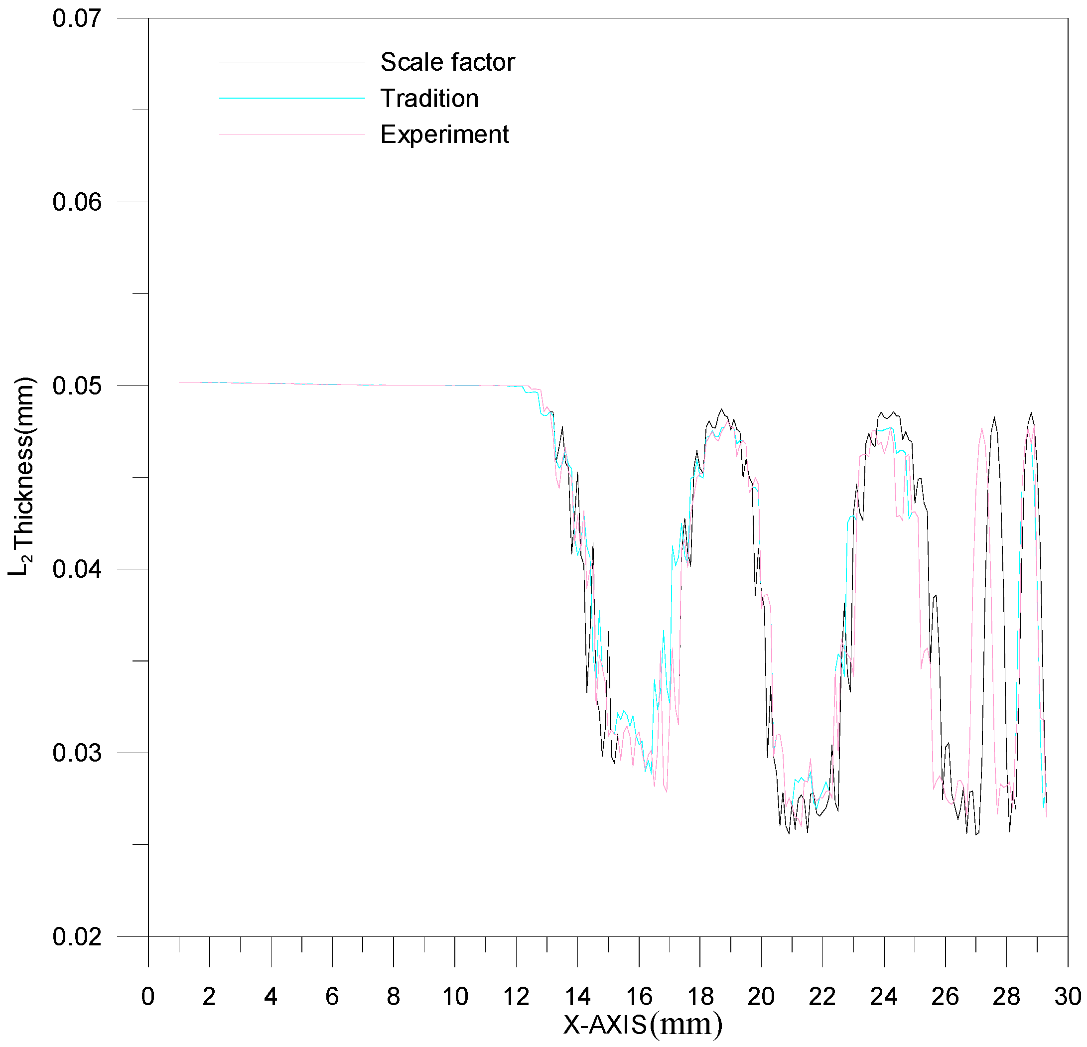
The thickness of the L1 section is shown in Figure 13. The range of thickness variation is 0.0264~0.033 mm. Based on Figure 13, the experimental result is between the results of the two theoretical models. In addition, among all the processed channels in one plate, the first channel is the thinnest. The thickness variations for these three results (experimental results, traditional material models and modified scale-factor material model) are similar, and no significant error is observed. The thickness of the L2 section is shown in Figure 14. The L2 section is thicker than the L1 section. The thickness difference is about 0.003 mm.
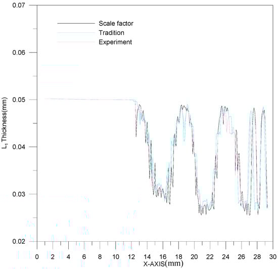
Figure 13.
The thickness variation of the L1 section.
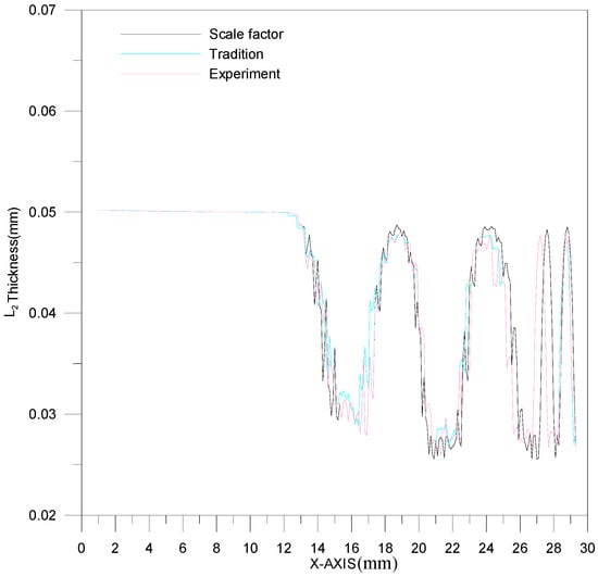
Figure 14.
The thickness variation of the L2 section.
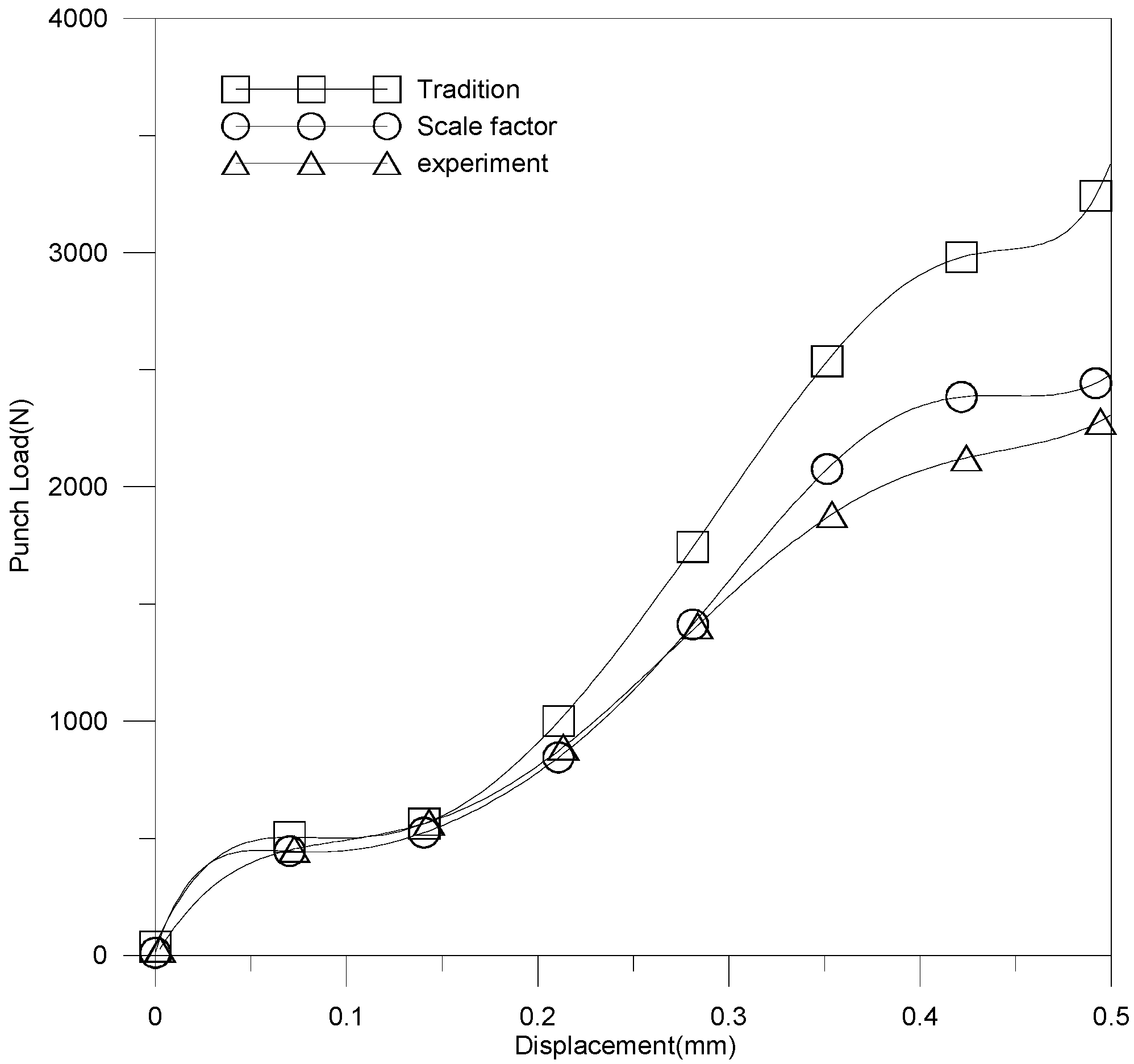
The relationship of punch load and stroke is revealed in Figure 15. The curve variations for these three results (experimental results, traditional material model and modified scale-factor material model) are similar; namely, the punch load increased with increasing stroke. However, significant errors are observed once the stroke exceeds a threshold. The large error is due to the increase in contact area between die and blank. According to Figure 15, the simulation results for the modified scale-factor material model is much better than those of traditional material model.

Figure 15.
The relationship of punch load and stroke.
4.2. Effect of Tool Radius on the Micro-Channel Array Forming Process of Stainless Steel Plates
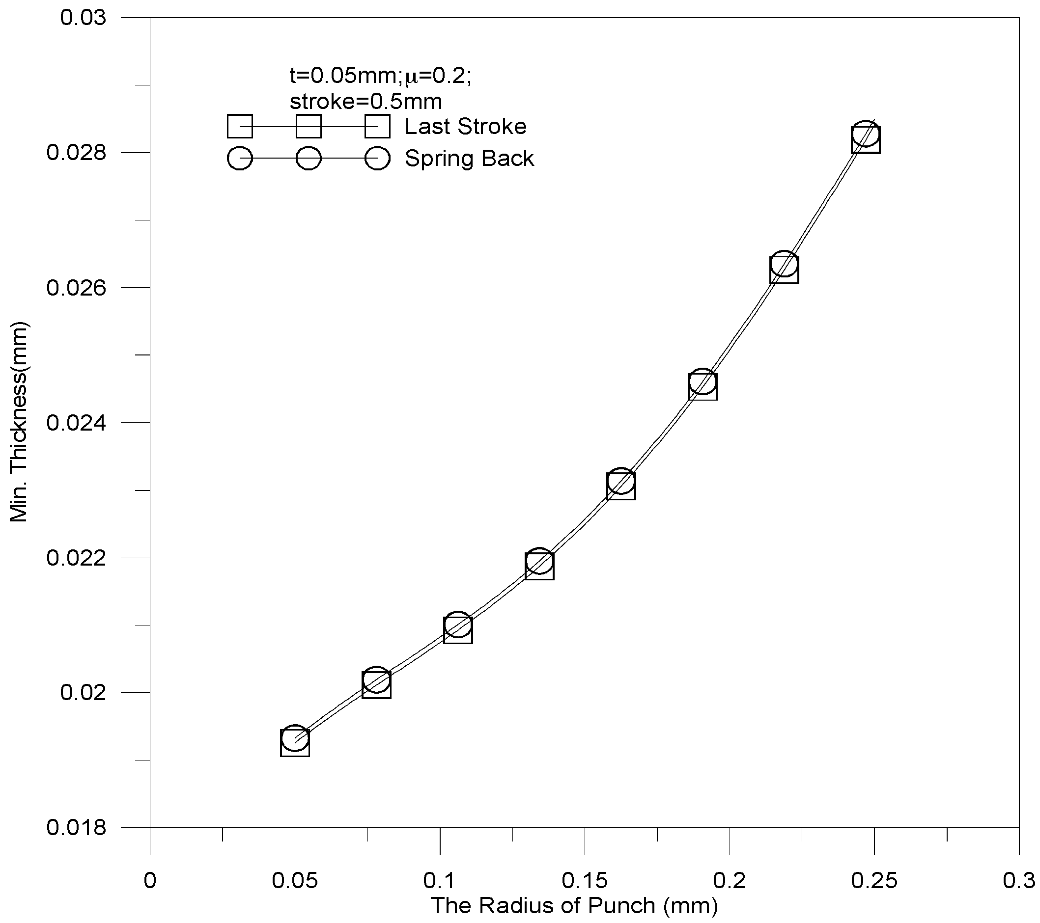
The dimensional effect of punch fillet radius on the thickness of stainless steel plate is demonstrated in Figure 16. The parameters of the micro-channel array forming process are as follows:

Figure 16.
The relationship between sheet thickness and punch fillet radius.
- *
- Punch fillet radius: 0.05 mm, 0.1 mm, 0.15 mm, 0.2 mm, and 0.25 mm
- *
- Stroke: 0.5 mm
- *
- Coefficient of friction: 0.2
- *
- Blank thickness: 0.5 mm
The thickness increases linearly when the fillet radius is increased. The minimal thickness is 0.0201 mm against a punch fillet radius of 0.05 mm. The thickest sheet thickness is 0.0278 mm against a punch fillet radius of 0.25 mm. Apparently, an acute angle of channel would be formed more easily by a small punch fillet radius than by a large one, and may lead to material fracture. The punch load against stroke under various punch fillet radiuses is reported in Figure 17. It should be noticed that a small punch fillet radius leads to a large punch load; e.g., the maximal load (about 5000 N) is induced by a tool radius of 0.05 mm. As a result, the punch load can be reduced by increasing the punch fillet radius.
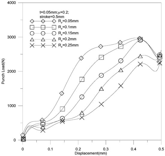
Figure 17.
Punch load against stroke under various punch fillet radiuses.
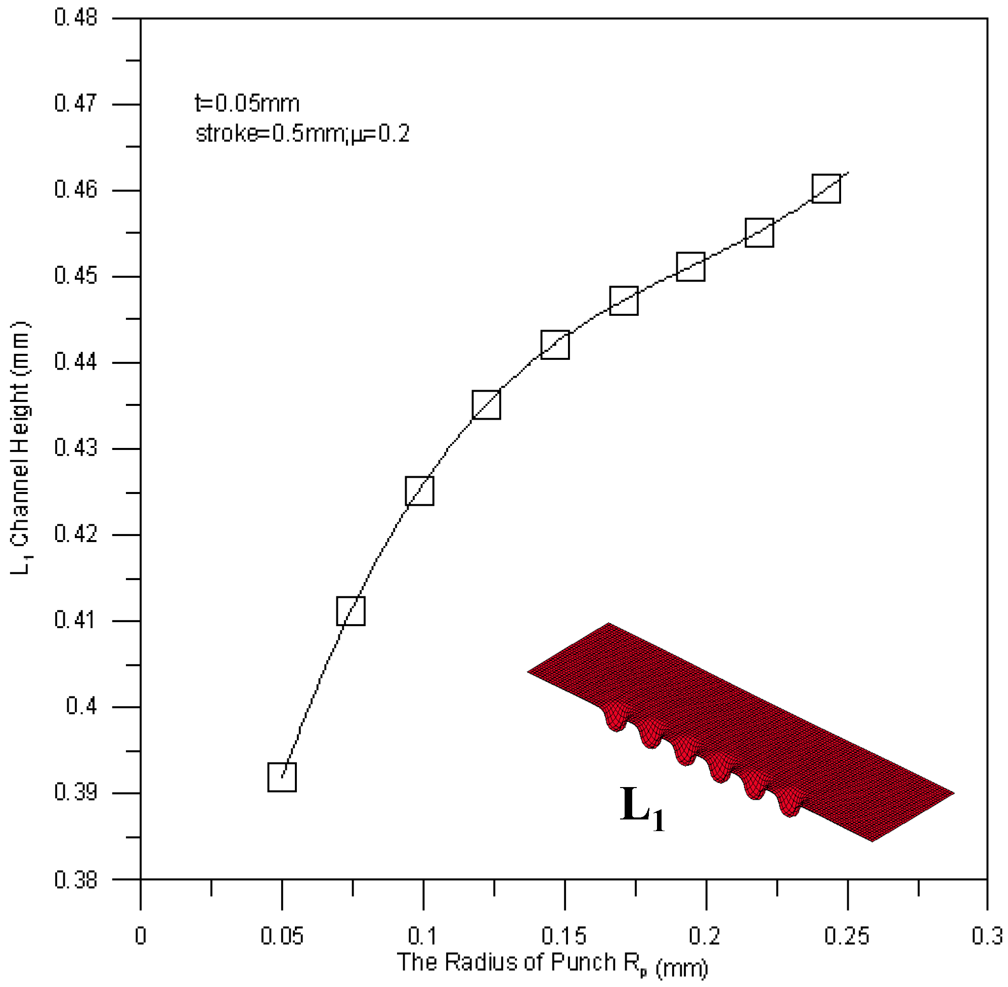
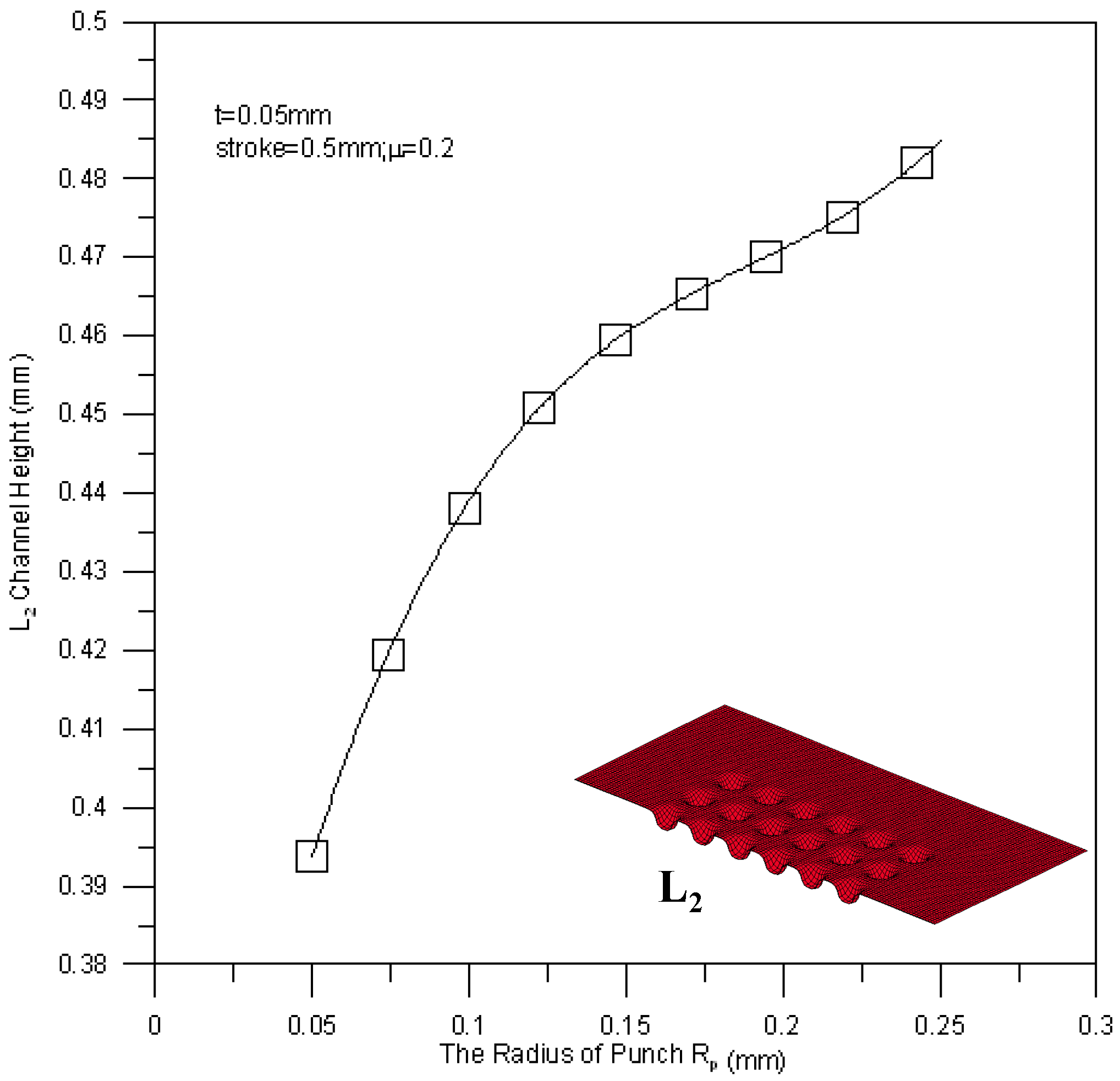
Figure 18 shows the relationship between the mean channel height of the L1 section and the punch fillet radius. A large punch fillet radius leads to a high channel height of the L1 section, e.g., the maximum mean channel height is achieved by a punch fillet radius of 0.25 mm. Since the flowability of material is regulated by the fillet radius, the deep drawing process can be performed more smoothly when a large fillet radius is applied. The mean channel height of the L2 section against fillet radius is shown in Figure 19. The variation trend of the L2 section height is similar to that of the L1 section height, but the measured height of the L2 section is a little bit higher than the height of the L1 section (about 0.02 mm). This is due to the reducing of the peripheral contact area of the channel by buckling.
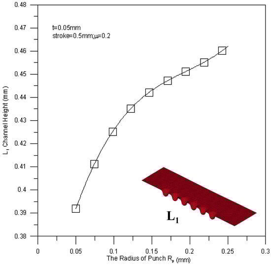
Figure 18.
The relationship between the tool radius and the channel height of the L1 section.
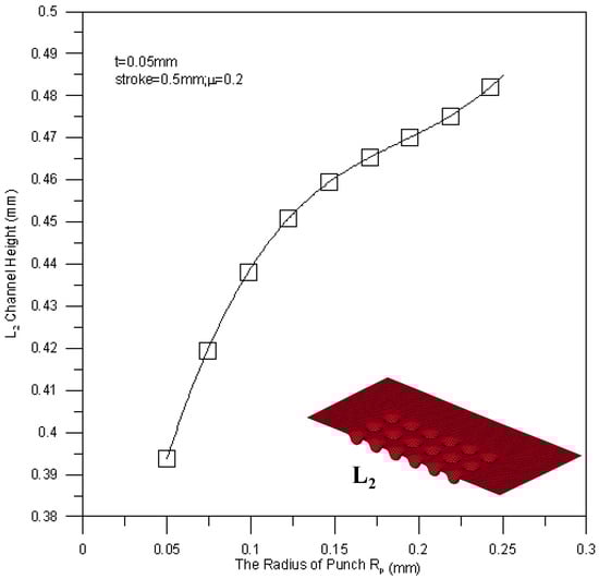
Figure 19.
The relationship between the tool radius and the channel height of the L2 section.
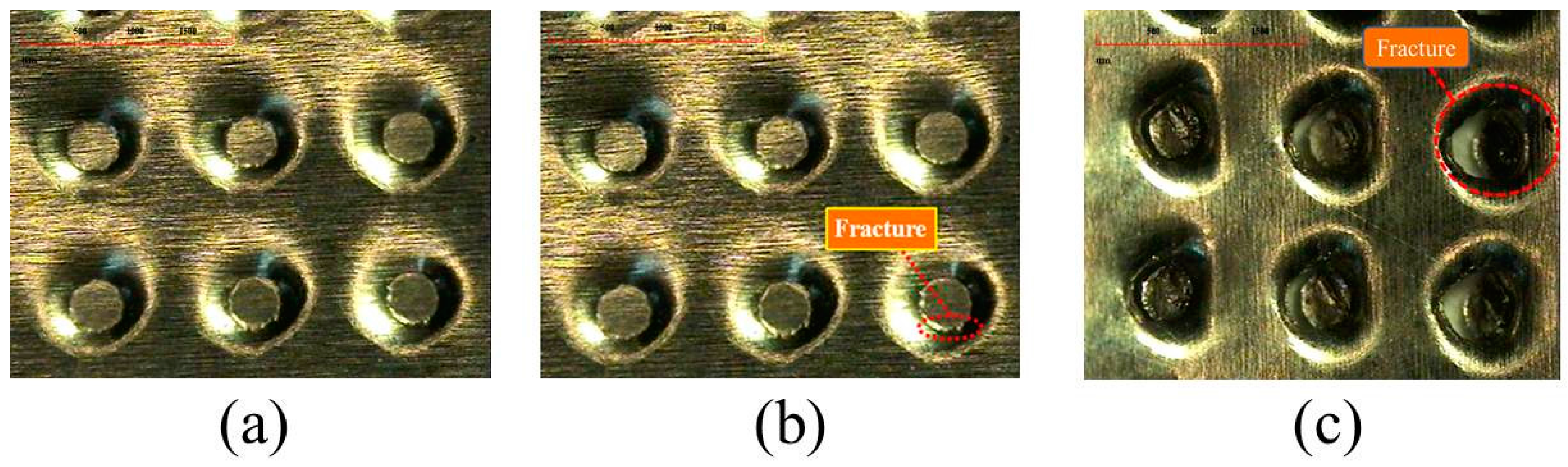
The practically processed workpieces are shown in Figure 20. In total, five kinds of strokes have been applied in the experiments, including 0.4 mm, 0.45 mm, 0.5 mm, 0.55 mm and 0.6 mm. Significant fractures have been observed in the plates at strokes of 0.55 mm and 0.6 mm. As a result, the stroke limitation for micro-channel array deep drawing processes in this work is about 0.5 mm.
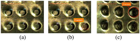
Figure 20.
Processed stainless steel plate (a) stroke of 0.5 mm; (b) stroke of 0.55 mm; (c) stroke of 0.6 mm.
5. Conclusions
3D elastic-plastic finite element analysis has been employed in this work to analyze the micro-channel array deep drawing process for stainless steel plate. The r-minimum rule is applied to simplify the calculation during the non-linear process. The main results are summarized as follows:
- (1)
- The maximum channel depth for a 50 μm stainless steel sheet is about 0.5 mm. This is verified by both of the simulation results and the experimental results.
- (2)
- On the basis of the finished workpieces, the material fracture is mainly located in the contact area between the punch and the bottom die fillet. As a result, more attention should be devoted to fillet radius design.
- (3)
- The deep drawing process can be performed more smoothly when a large fillet radius is applied. In other words, a small tool fillet radius may lead to an increase of fracture.
- (4)
- The simulation performance of the modified scale-factor material model is better than that of the traditional material model.
Acknowledgments
This research was sponsored by the Ministry of Science and Technology in Taiwan under Grants MOST 105-2221-E-167-007.
Author Contributions
T.-C. Chen and J.-C. Lin conceived and designed the experiments; J.-C. Lin performed the experiments; T.-C. Chen, J.-C. Lin and R.-M. Lee analyzed the data; T.-C. Chen and R.-M. Lee contributed reagents/materials/analysis tools; R.-M. Lee wrote the paper.
Conflicts of Interest
The authors declare no conflict of interest.
References
- Yu, H.N.; Lim, J.W.; Suh, J.D.; Lee, D.G. A graphite-coated carbon fiber epoxy composite bipolar plate for polymer electrolyte membrane fuel cell. J. Power Sources 2011, 196, 9868–9875. [Google Scholar] [CrossRef]
- Kumar, A.; Ricketts, M.; Hirano, S. Ex situ evaluation of nanometer range gold coating on stainless steel substrate for automotive polymer electrolyte membrane fuel cell bipolar plate. J. Power Sources 2010, 195, 1401–1407. [Google Scholar] [CrossRef]
- Peng, L.; Lai, X.; Liu, D.; Hu, P.; Ni, J. Flow channel shape optimum design for hydroformed metal bipolar plate in PEM fuel cell. J. Power Sources 2008, 178, 223–230. [Google Scholar] [CrossRef]
- Petrach, E.; Abu-Isa, I.; Wang, X. Investigation of elastomer graphite composite material for proton exchange membrane fuel cell bipolar plate. J. Fuel Cell Sci. Technol. 2009, 6, 0310051–0310056. [Google Scholar] [CrossRef]
- Gautam, R.K.; Banerjee, S.; Kar, K.K. Bipolar plate materials for proton exchange membrane fuel cell application. Recent Pat. Mater. Sci. 2015, 8, 15–45. [Google Scholar] [CrossRef]
- Koc, M.; Mahabunphachai, S. Feasibility investigations on a novel micro-manufacturing process for fabrication of fuel cell bipolar plates: Internal pressure-assisted embossing of micro-channels with in-die mechanical bonding. J. Power Sources 2007, 172, 725–733. [Google Scholar] [CrossRef]
- Iranzo, A.; Munoz, M.; Lopez, E.; Pino, J.; Rosa, F. Experimental fuel cell performance analysis under different operating conditions and bipolar designs. Int. J. Hydrogen Energy 2010, 35, 11434–11447. [Google Scholar] [CrossRef]
- Kakati, B.K.; Yamsani, V.K.; Dhathathreyan, K.S.; Sathiyamoorthy, D.; Verma, A. The electrical conductivity of a composite bipolar plate for fuel cell applications. Carbon 2009, 47, 2413–2418. [Google Scholar] [CrossRef]
- Mahabunphachai, S.; Koc, M. Fabrication of micro-channel arrays on thin metallic sheet using internal fluid pressure: Investigations on size effects and development of design guidelines. J. Power Sources 2008, 175, 363–371. [Google Scholar] [CrossRef]
- Hu, P.; Peng, L.; Zhang, W.; Lai, X. Optimization design of slotted-interdifitated channel for stamped thin metal bipolar plate in proton exchange membrane fuel cell. J. Power Sources 2009, 187, 407–414. [Google Scholar] [CrossRef]
- Park, Y.-C.; Lee, S.-H.; Kim, S.-K.; Lim, S.; Jung, D.-H.; Lee, D.-Y.; Choi, S.-Y.; Ji, H.; Peck, D.-H. Performance and long-term stability of Ti metal and stainless steels as a metal bipolar plate for a direct methanol fuel cell. Int. J. Hydrogen Energy 2010, 35, 4320–4328. [Google Scholar] [CrossRef]
- Peng, L.F.; Hu, P.; Lai, X.M.; Mei, D.Q.; Ni, J. Investigation of micro/meso sheet soft punch stamping process-simulation and experiments, materials and design. Mater. Des. 2009, 30, 783–790. [Google Scholar] [CrossRef]
- Zhang, B.; Zhang, Y.F.; He, H.; Li, J.M.; Yuan, Z.Y.; Na, C.R.; Liu, X.W. Development and performance analysis of a metallic micro-direct methanol fuel cell for high-performance applications. J. Power Sources 2010, 195, 7338–7348. [Google Scholar] [CrossRef]
- Chen, Y.L.; Zhan, H.B.; Lee, S.J.L.; Zhu, S.M. Micro-ECM of maze flow channel on bipolar plates of fuel cell. Key Eng. Mater. 2011, 458, 125–130. [Google Scholar] [CrossRef]
- Qiu, D.; Yi, P.; Peng, L.; Lai, X. Channel dimensional error effect of stamped bipolar plates on the characteristics of gas diffusion layer contact pressure for proton exchange membrane fuel cell stacks. J. Fuel Cell Sci. Technol. 2015, 12, 041002. [Google Scholar] [CrossRef]
- Imanmehr, S.; Pourmahmod, N. A parameteric study of bipolar plate structural parameters on the performance of proton exchange membrane fuel cell. J. Fuel Cell Sci. Technol. 2012, 9, 051003. [Google Scholar] [CrossRef]
- Kianimanesh, A.; Yu, B.; Yang, Q.; Freiheit, T.; Xue, D.; Park, S.S. Investigation of bipolar plate geometry on direct ethanol fuel cell performance. Int. J. Hydrogen Energy 2012, 37, 18403–18411. [Google Scholar] [CrossRef]
- Park, W.T.; Jin, C.K.; Kang, C.G. Improving channel depth of stainless steel bipolar plate in fuel cell using process parameters of stamping. Energy Convers. Manag. 2016, 124, 51–60. [Google Scholar] [CrossRef]
- McMeeking, R.M.; Rice, J.R. Finite-element formulations for problems of large elastic-plastic deformation. Int. J. Solids Struct. 1975, 11, 601–616. [Google Scholar] [CrossRef]
- Hinton, E.; Owen, D.R. Finite Element Software for Plates and Shell; Pineridge: Swansea, UK, 1984. [Google Scholar]
- Hughes, T.J.R. The Finite Element Method; Prentice-Hall: Englewood Cliffs, NJ, USA, 1987. [Google Scholar]
- Hughes, T.J.R. Generalization of selective integration procedures to anisotropic and nonlinear media. Int. J. Numer. Methods Eng. 1980, 15, 1413–1418. [Google Scholar] [CrossRef]
- Adam, F.M.; Mohamed, E.; Hassaballa, A.E. Degenerated four nodes shell element with drilling degree of freedom. J. Eng. 2013, 3, 10–20. [Google Scholar]
- Peng, L.F.; Liu, F.; Ni, J.; Lai, X.M. Size effects in thin sheet metal forming and its elastic-plastic constitutive model. Mater. Des. 2007, 28, 1731–1736. [Google Scholar] [CrossRef]
- Huang, Z.G.; Li, J.W. Heating and thermostatic analysis of an oven-controlled quartz crystal oscillator. Smart Sci. 2016, 4, 45–51. [Google Scholar] [CrossRef]


© 2017 by the authors. Licensee MDPI, Basel, Switzerland. This article is an open access article distributed under the terms and conditions of the Creative Commons Attribution (CC BY) license (http://creativecommons.org/licenses/by/4.0/).