Article

Operational Problems Associated with the Use of Biogas as an Alternative Energy Source for Powering Cogeneration Systems


by
Krystian Hennek
1,*,
Jarosław Mamala
1,
Andrzej Bieniek
1,
Mariusz Graba
1,
Patryk Stasiak
2,
Krystian Czernek
1,
Sylwia Włodarczak
3,
Andżelika Krupińska
3,
Magdalena Matuszak
3 and
Marek Ochowiak
3,*
1
Faculty of Mechanical Engineering, Opole University of Technology, 45-758 Opole, Poland
2
Municipal Services in Opole Ltd., Podmiejska Street 69, 45-574 Opole, Poland
3
Department of Chemical Engineering and Equipment, Poznan University of Technology, 60-965 Poznan, Poland
*
Authors to whom correspondence should be addressed.
Energies 2026, 19(6), 1566; https://doi.org/10.3390/en19061566
Submission received: 5 February 2026 / Revised: 4 March 2026 / Accepted: 19 March 2026 / Published: 22 March 2026
(This article belongs to the Special Issue Internal Combustion Engines: Research and Applications—3rd Edition)

Abstract

In this article operational problems associated with the use of landfill biogas as an alternative fuel in cogeneration systems, with particular emphasis on micro-installations based on the Perkins 4008-30 TRS2 combustion engine are presented. Such installations are commonly used in cogeneration systems, whose importance in obtaining stable electric and thermal energy is growing, especially when taking into account the additional reduction in environmental impact through biogas combustion. Reducing emissions of biogas, which consists of approximately 60% methane and approximately 35% carbon dioxide, directly reduces emissions of a greenhouse gas (GHG) with a high global warming potential (GWP). In this study the characteristics of the landfill, the biogas purification system, the measurement system and the energy balance of the entire process, biogas production → electric energy → thermal energy, are presented and the importance of this type of installation in the context of a low-carbon economy is discussed. Attention is also drawn to the operational problems of the cogeneration system, which led to its failure, requiring comprehensive repairs of the internal combustion engine.

1. Introduction

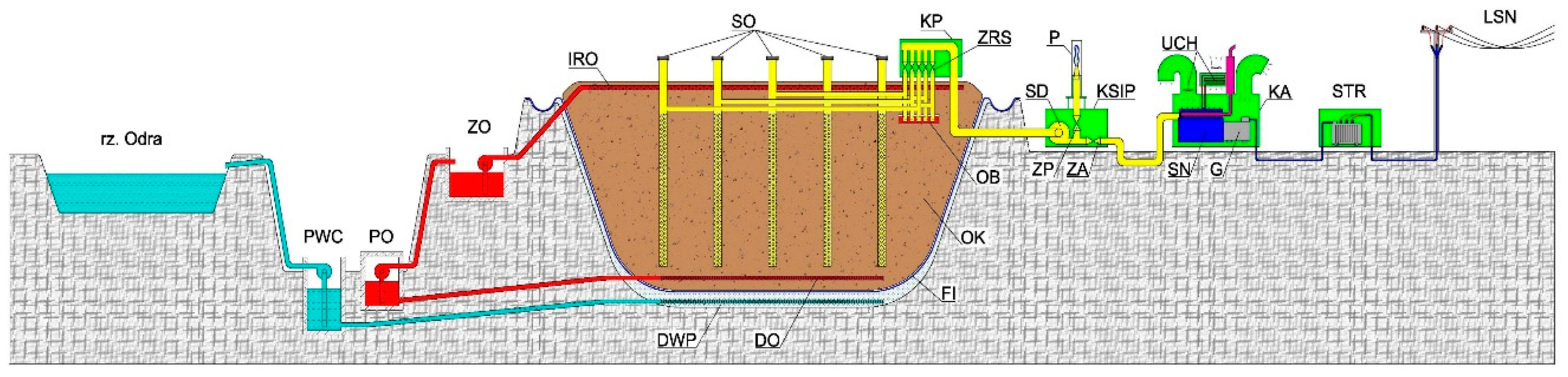
Dynamic changes in the energy sector, resulting from global climate policy and the need to reduce greenhouse gas emissions, are driving increased interest in renewable and alternative energy sources [1,2,3,4,5]. Landfill biogas, produced by the anaerobic decomposition of organic waste in old landfills, plays an important but often underestimated role in this regard. It is extremely important that these landfills are monitored for environmental impact and equipped with installations that allow biogas to be captured. For this purpose, a system of degassing wells, drains and collectors is used to extract biogas and direct it to a cogeneration system, thus limiting uncontrolled methane emissions (Figure 1). In the case of low landfill capacity, intermediate tanks or flaring are used, which in themselves are harmful to the environment. In places where waste is stored illegally, e.g., agricultural waste or other biodegradable fractions, without degassing installations, biogas escapes directly into the atmosphere, constituting a significant source of greenhouse gas emissions.
Biogas obtained from a landfill site, whose main component is methane, constitutes a significant source of uncontrolled greenhouse gas emissions into the atmosphere if it is not utilized. The global warming potential (GWP) of methane over a 100-year period is approximately 27–30, which means that a unit of methane has several dozen times more impact on the climate than the same amount of carbon dioxide. An additional problem associated with biogas emissions is that the methane it contains is about 200 times less abundant in the atmosphere and remains there for only about a decade on average, whereas carbon dioxide can last for centuries. In other words, methane causes rapid damage but disappears quickly, while CO2 consistently traps less heat than CH4, but decade after decade. However, the situation is changing, according to Jessika Trancik, associate professor at MIT’s [7]. The response of the environment varies depending on how far back the period of methane volatilization is analyzed. According to the author, releasing 1000 kg of methane and CO2 into the atmosphere today causes methane to immediately begin blocking a significant amount of heat—at least 100 times more than CO2. However, methane begins to decompose and leaves the atmosphere relatively quickly. Over time, more and more of that original ton of methane disappears, and the permanent warming effect of CO2 slowly fills the gap in the atmosphere, trapping the heat from the released methane. Thus, over 20 years, methane traps about 80 times more heat than the same amount of CO2, and over 100 years, that original ton of methane would trap about 28 times more heat than a ton of carbon dioxide.
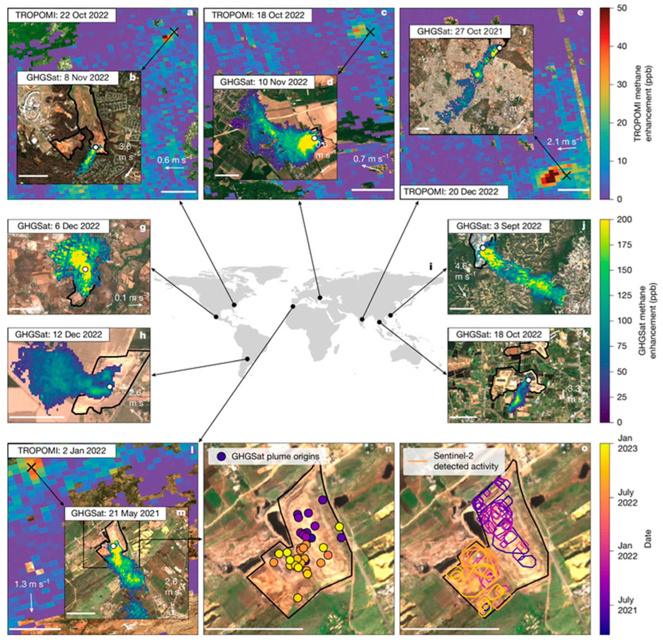
At the same time, population growth is causing an increase in the amount of municipal waste and an increase in these uncontrolled emissions, as shown in Figure 2. According to [8], municipal waste landfills account for about 12% of human-induced methane emissions and represent the third-largest source globally. The latest technological advances, including space technology and specially dedicated satellites, are used to monitor emissions.
Therefore, the capture and simultaneous energy use of biogas is one of the fastest and most cost-effective climate protection measures. From an energy perspective, landfill biogas can be successfully used as an alternative fuel in cogeneration systems, enabling the simultaneous production of electric and thermal energy. This approach not only allows for the effective use of local renewable energy sources, but also improves energy security and, above all, reduces GHG emissions and fossil fuel consumption [10], especially in small and medium-scale heating systems.
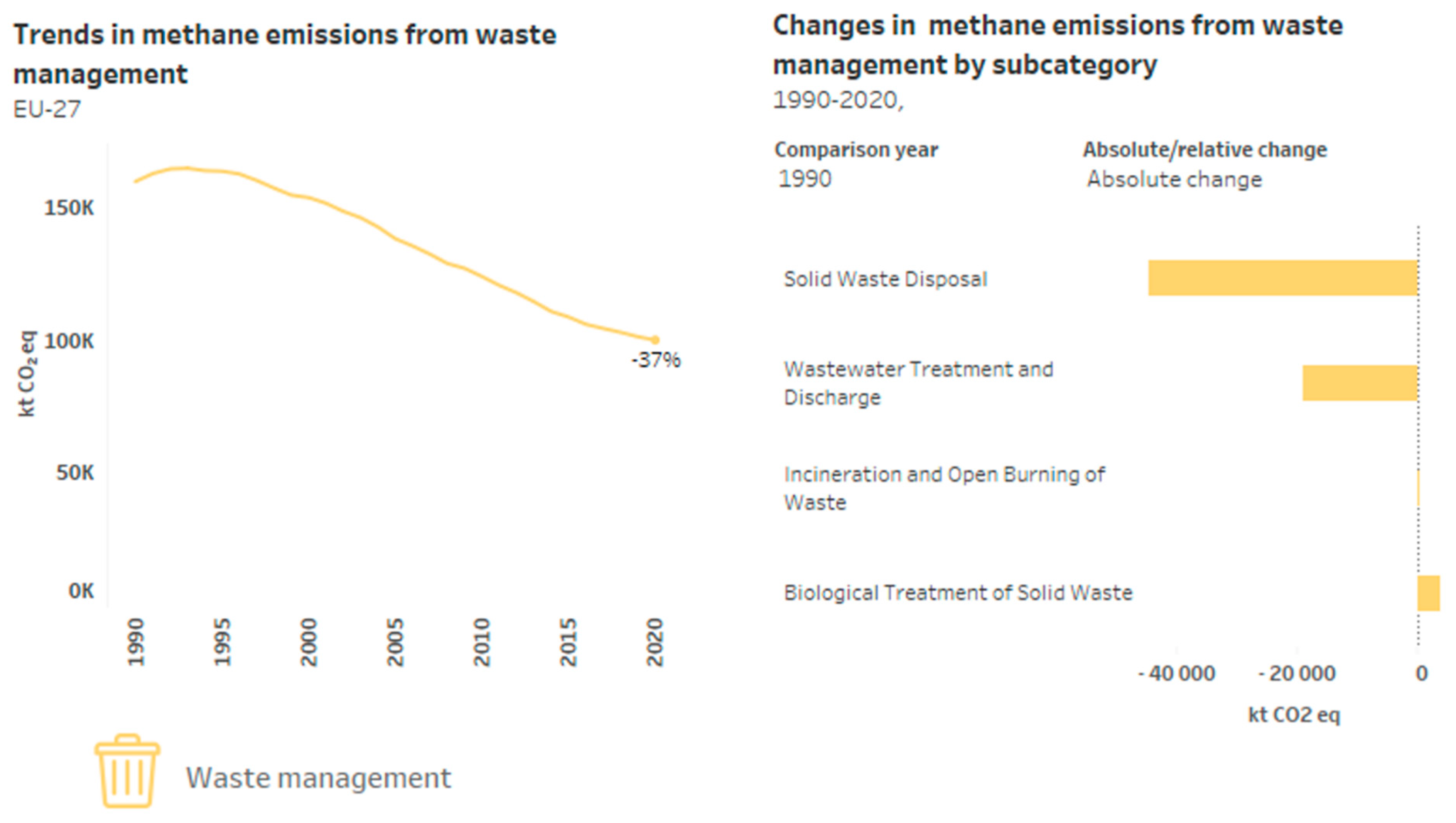
Effective methane management reduces GHG emissions by up to 37% over 30 years (Figure 3).
The municipal waste landfill analyzed is not located in a large urban agglomeration but has been serving an area inhabited by approximately 300,000 people for over 30 years. The scale of the facility’s operation has enabled the implementation of a landfill management system that includes biogas capture, which is used to power a 505 kW cogeneration unit. At the same time, the operation of such installations involves numerous technical challenges resulting from the variability of biogas composition, weather conditions and the presence of pollutants (including H2S, siloxanes, chlorine and fluorine compounds), which affect the durability and reliability of the combustion engines [8] that form the basis of the cogeneration system. It should also be noted that these units are characterized by very high availability of 8200 h per year [12,13]. This, in turn, is associated with increased wear and tear, high thermal loads and fatigue. Maintaining such a unit in proper technical condition requires a high-maintenance regime and the use of consumables with appropriate parameters.

2. Motivation for Addressing the Topic and Methodology of the Research

In many scientific studies, and in practice in modern biogas plants, activities focus mainly on the latest installations for the simultaneous capture of methane and carbon dioxide. These types of biogas upgrading and purification installations operate on the principle of removing CO2, H2S, ammonia and trace compounds in order to obtain pure biomethane with parameters similar to those of natural gas. CO2 capture and conversion, including chemical absorption (e.g., in KOH or amine solutions) and adsorption on porous materials, not only allow the biogas stream to be purified, but also enable the captured CO2 to be utilized, e.g., in industrial applications or in electrochemical conversion processes for the production of liquid fuels such as ethanol. Despite the development of these modern technologies, the exploitation of existing landfills with biogas utilization installations remains crucial. It allows the captured methane potential to be used up and the emissions from currently inactive landfill sites to be reduced [14]. However, it is less common due to high costs of the investment. According to the report ‘Biogenic CO2 from biogases’ [15], in most of Europe, but also in Poland, almost all cogeneration systems operate without CO2 capture—the share of the latest CCS/CCU (Carbon Capture and Storage/Carbon Capture and Utilization) installations is negligible (per mile). Most often, these are installations with a capacity of up to 250 kW, which operate exclusively for the purpose of electric energy production. In Poland, only 10% of this type of cogeneration installations [16] use thermal energy for their own needs, with an average annual utilization rate of approximately 50% of waste heat [17]. The problem is even greater because many municipal waste landfills in Europe capture biogas but do not exploit its potential. For example, in Poland, as many as 87.3% of landfills carry out this process, of which 30% is burned in cogeneration systems and 70% is burned directly on landfill fields. Controlled combustion of biogas is carried out in special flares, the purpose of which is to safely dispose of it and reduce the risk of spontaneous combustion in landfills, minimize unpleasant odors and reduce greenhouse gas emissions into the atmosphere [18,19,20]. In 2024, utilization of landfill biogas in cogeneration systems allowed us to produce (recover) approximately 132.1 M MJ of thermal energy and approx. 129.4 M kWh of electric energy [21].
In broader terms, including all existing municipal waste landfills, it is estimated that there are over 100,000 of them in the Baltic Sea region and their lifespan, even after closure, is up to 30 years of continuous biogas production. Therefore, the exploitation of existing old waste landfills is very important, because by using a cogeneration system, under conditions of full utilization of the chemical energy of biogas, we can obtain 40% mechanical power on the electricity generator shaft and approximately 38.5% gross electrical power, which corresponds to a generator efficiency of 96%. A side effect of the biogas combustion process is high-temperature heat (exhaust gases and housing cooling) and low-temperature heat (mixture cooling), the use of which enables a total energy efficiency of the cogeneration system of 80–85% in full heat utilization mode [22,23]. Due to the need to maintain the highest energy efficiency, it is desirable to fully load the cogenerator, but this involves thermal loading on the combustion engine and its working mechanisms, which causes operational problems [24]. This study analyses the period (covering the years from 2020 to 2025) of operation of a cogeneration system running on landfill biogas without CO2 capture, but using waste heat for the plant’s needs. The municipal waste landfill and cogeneration systems described will continue to be used for many years to come.
The analysis methodology is based on a case study approach and includes an analysis of the municipal waste landfill site, the properties of the biogas obtained, an analysis of the cogeneration system’s performance indicators, the results of post-operation tests on engine oil samples, and operational issues.

3. Subject of Analysis

3.1. Characteristics of the Landfill and Gas Field

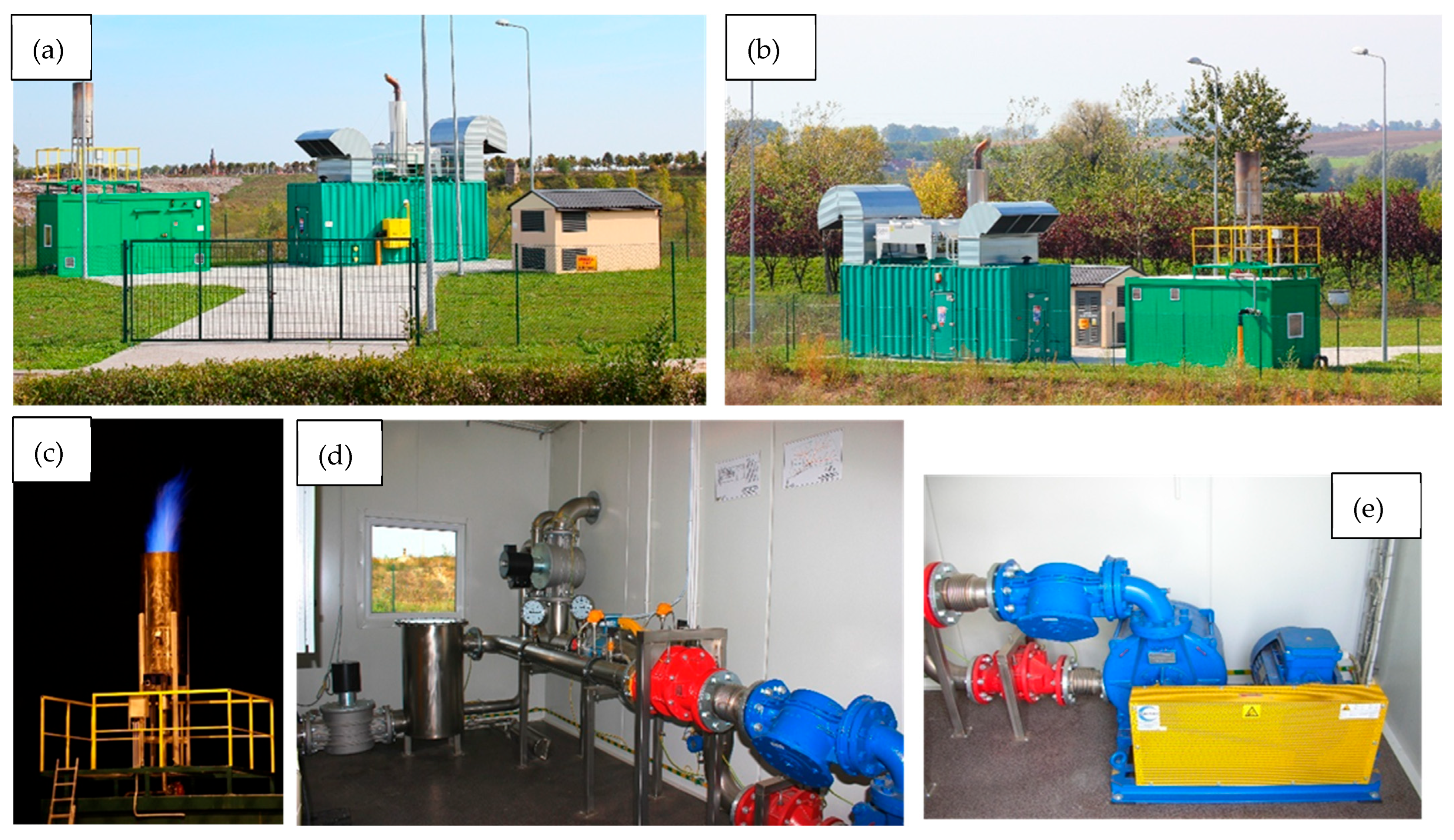
The municipal waste landfill in question has been in operation for over 30 years. The long period of municipal waste disposal before the introduction of regulations on its biological treatment translates into long-term biogas generation. According to forecasts [6], the facility is to be operated in its current form until 2030, and the current biogas production potential is 250 Nm3/h, which forecasts an electricity generation capacity of 500 kW. The landfill comprises two sections with a total area of 21.3 hectares. The landfill (Figure 1) has been equipped with a bio-power plant system comprising: degassing wells (approximately 40), a sub-foil drain, gas collectors, a suction-blower, a biogas preparation container, a flare, and a cogeneration unit container connected to a 0.4/15 kV transformer station. The individual components are shown in Figure 4.

3.2. Biogas Purification and Preparation System

Biogas from degassing wells is transported to a preparation station, where it undergoes:
  • Separation of condensate and solid particles;
  • Desulphurization using an iron hydroxide-based bed (SULFAX);
  • Fine filtration;
  • Pressure and temperature stabilization before being fed into the engine.
The internal combustion engine manufacturer’s requirements for gaseous fuel include: minimum lower calorific value, methane number, permissible H2S content, total chlorine and fluorine compounds, volatile silicon compounds (siloxanes), maximum moisture content, highest supply pressure and temperature range.
The characteristic parameters of the obtained biogas are checked periodically, with no significant fluctuations in their values:
  • Methane content CH4 ≈ 51.8%;
  • Lower calorific value Wu ≈ 17.64 MJ/Nm3 (≈4.9 kWh/Nm3);
  • Methane number MN ≈ 135;
  • Presence of siloxanes with a total concentration of approx. 2.78 mg/Nm3, which corresponds to approx. 5.37 mg Si/Nm3 CH4 [4];
  • Elevated concentrations of volatile organic compounds (VOCs) with low solid particle content.
A problem for landfill biogas is the concentration of H2S, which reaches values of 1600–1700 ppm in raw gas, requiring effective desulphurization to lower the sulphur content to an acceptable level (suitable for combustion in the internal combustion engine according to its manufacturer’s recommendations), in order to reduce corrosion loads and improve the durability of the cogeneration unit [25,26].

3.3. Perkins 505 kW Cogeneration Unit

The subject of the analysis is the HE-EC-505541-PG505-B cogeneration unit based on a Perkins 4008-30TRS2 engine, provided by Perkins Engines Company Limited (company headquarters in Peterborough, UK) and a Leroy Somer LSA 49.3 S4 generator manufactured by Nidec Leroy-Somer (company headquarters in Angoulême, France). The combustion engine is an eight-cylinder in-line unit with cylinder diameter of 160 mm, stroke of 190 mm and displacement of 30.6 L, designed for continuous operation at crankshaft rotation speed of 1500 rpm.
The catalog data for full load of the combustion engine indicate:
  • Chemical energy demand of the fuel (Pf): 1312 kW;
  • Mechanical shaft power: 526 kW;
  • gross electrical power (Pe): 505 kW;
  • High-temperature thermal power (Pt): 541 kW;
  • Thermal power from housing cooling: 211 kW;
  • Thermal power in exhaust gases at 120 °C: 330 kW;
  • Thermal power from LT/HT (Low Temp/High Temp) mixture cooling: 90 kW [6].
Using these data, the overall efficiency η of the cogeneration system under maximal load can be calculated as the ratio of the output power (the sum of electrical Pe and thermal Pt power) to the input power (fuel energy input Pf):
η   =   P e + P t P f   ·   100 %
Substituting the data into the equation gives the result of 79.73% overall efficiency.
The combustion engine operates in a cogeneration system in which electric energy is partially self-consumed and fed into the medium-voltage grid, while high-temperature and low-temperature thermal energy is used for local heating needs, including domestic hot water heating and heating of the landfill and plant facilities. The total thermal power of the high-temperature and low-temperature circuits is estimated at 541 kW (heat recovery from exhaust gases 330 kW and housing cooling 211 kW).
The typical composition of landfill biogas is: 40 to 70% methane, 35–50% CO2 and admixtures of nitrogen < 40 ppm, oil vapor < 400 mg/m3, oxygen and water vapor up to a maximum humidity of 60%. In the analyzed landfill, tests showed a methane content of approximately 51.8%, carbon dioxide at 36–37%, as well as trace amounts of O2, H2S concentrations of up to 2000 ppm in raw gas before desulphurization and <200 ppm/m3 in gas fuel. The calorific value fluctuates slightly at Wu ≈ 18 MJ/Nm3 with a variability of 0.3%/min and the methane number is over 130. Therefore, the capture biogas obtained from the municipal landfill falls within the typical values for an internal combustion engines fuel [27].

3.4. Measuring System

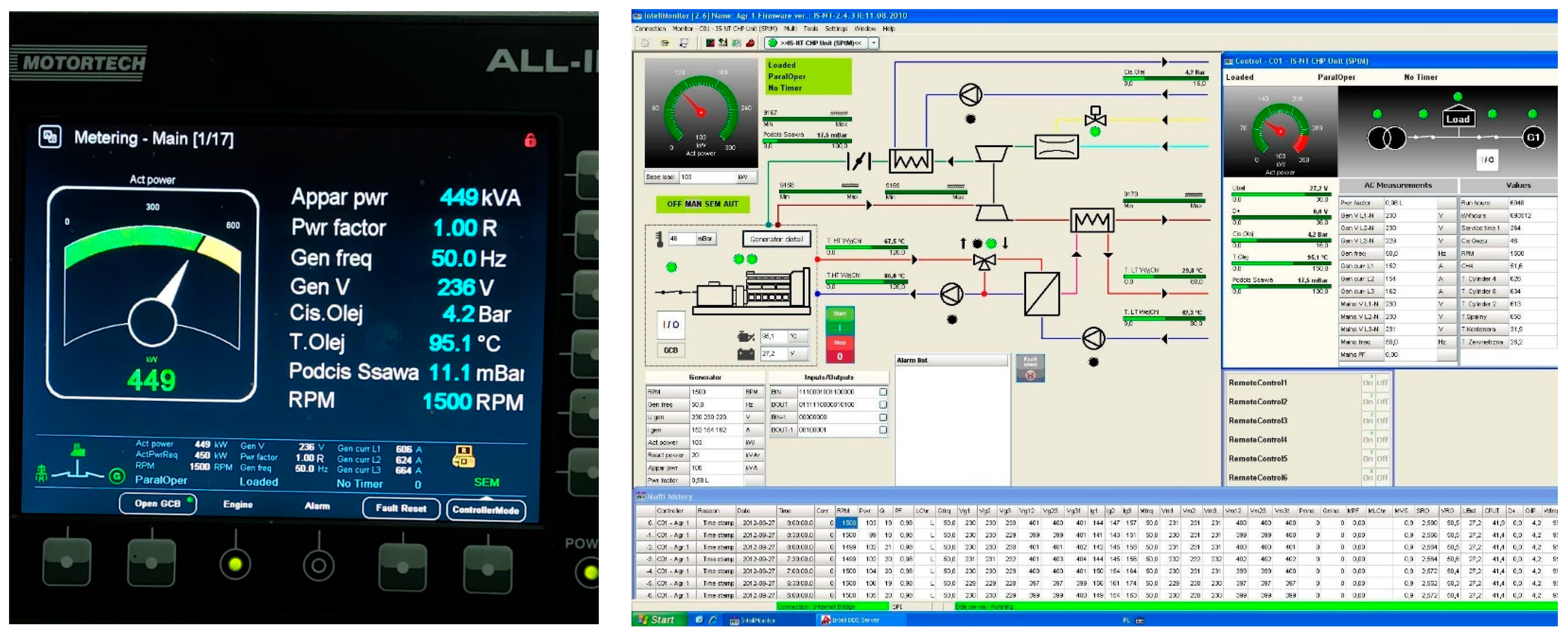
The cogeneration system is equipped with an extensive control and monitoring system based on InteliMonitor and InteliVision controllers (Figure 5), which record electrical, thermal and process parameters. The basic parameters monitored in real time include:
  • Active, reactive and apparent power, current and voltage, generator power factor;
  • Engine speed, generated frequency and grid frequency;
  • Oil pressure, oil temperature, LT/HT circuit temperatures;
  • Vacuum pressure on the intake manifold, supply gas pressure and temperature;
  • Mixture temperature, charge air temperature;
  • Temperatures of individual cylinders (1–8);
  • Exhaust gas and container component temperatures;
  • Instantaneous biogas composition as input data for corrections in the fuel and ignition systems.
Figure 5. Monitoring of indicators and operating parameters of the cogeneration system.
Energies 19 01566 g005
The system allows for the recording of events in which threshold values have been exceeded, along with the parameters at the time of occurrence, which is important in analyzing the operation of the unit, its energy efficiency and the causes of possible technical failures.
In addition, the following are carried out [4]:
  • Periodic testing of biogas composition (main composition, H2S, siloxanes, and VOC) [28];
  • Analyses of the condition of the engine oil in an external laboratory, including: oil viscosity, TBN (Total Base Number), TAN (Total Acid Number), content of wear metals, silicon, sodium, water and oxidation products [29].

3.5. Analysis of Biogas Consumption and Energy Production

Based on the catalog data of the cogeneration system [6] and the results of power measurements, it is possible to estimate biogas consumption and electric and thermal energy production at various operating points. Assuming full load of the cogeneration system (505 kW gross electrical power), fuel consumption is approx. 219 Nm3/h of biogas, which corresponds to its chemical energy flow of approx. 1312 kW.
The annual operating time of the system, taking into account technological breaks, can be estimated at approximately 8000 h. The annual electric energy production possible during this time is 4.0 GWh, and the production of useful heat (high- and low-temperature) will range from 5.0 to 5.5 GWh (18,000–19,800 GJ), depending on the degree of utilization by heat consumers. Thus, over the course of a year, such an installation is capable of generating significant amounts of energy using renewable fuels, thereby reducing the consumption of fossil fuels and reducing CO2 emissions by 2600 tons from coal-based energy [30,31]. It should be noted that the analysis covers a single medium-sized municipal waste landfill site.

4. Operational Problems of the Cogeneration System

4.1. Landfill Site for Municipal Waste Other than Hazardous and Inert Waste

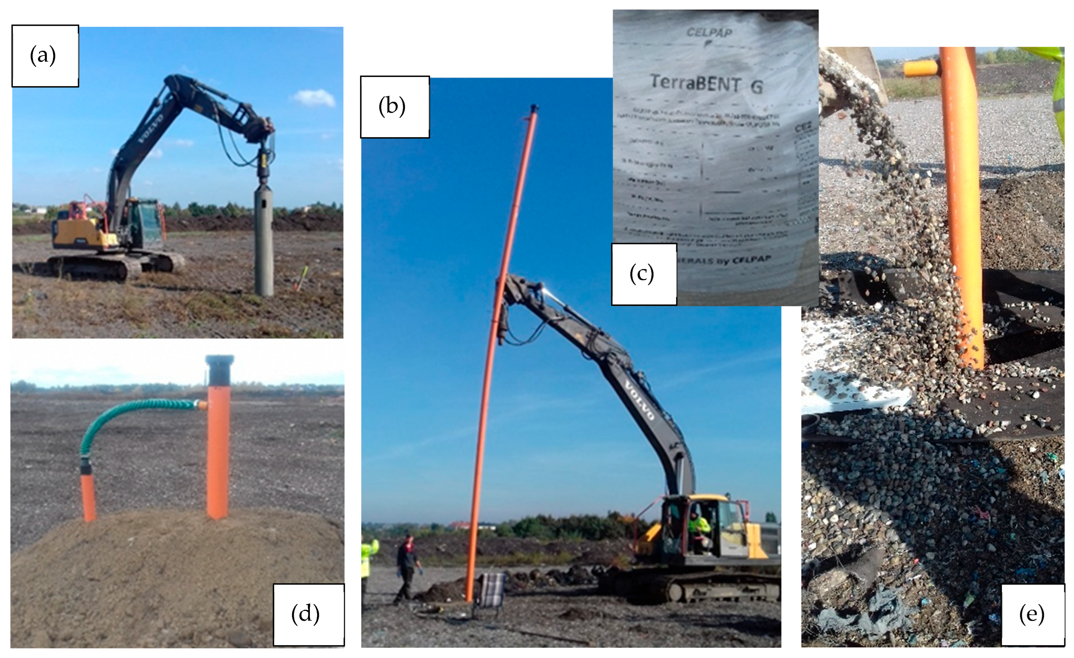
The municipal waste landfill analyzed is gradually decreasing in efficiency as it is exploited, hence, a reduction in biogas production potential is observed. It is impossible to maintain the level of energy production corresponding to the operation of the cogeneration system at full capacity. In practice, this means that it is necessary to periodically verify the biogas production capacity, analyze the emission (degassing) wells and possibly expand them with additional biogas sources. For technical reasons, old wells become contaminated and their cleaning is not cost-effective. Therefore, new wells are drilled, as was the case here. In 2021, a review was carried out and new raw biogas emission wells were constructed (Figure 6).
As a result of the construction of new biogas wells, the capacity of the landfill site has increased from 120 Nm3/h to the current level of 219 Nm3/h.
The technological system for obtaining raw biogas includes: emission wells (approx. 40), gas collectors, a suction-pressure pump system, a flare, and a biogas preparation container. The overhaul of the gas field also included improving the sealing by changing the way the wells are connected to the gas pipelines and changing the filter materials for raw gas in order to increase the stability of the biogas parameters.

4.2. Raw Biogas Purification

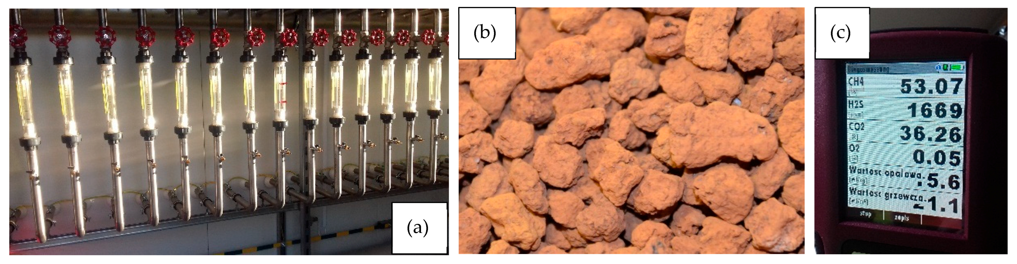
During the purification process, biogas from wells undergoes condensate separation, solid particle filtration, desulphurization, and pressure and temperature regulation. For purification, a desulphurize filled with an iron hydroxide-based sorbent (e.g., SULFAX) is used, which binds H2S to sulphate forms. Maintaining the correct biogas parameters requires continuous monitoring and periodic replacement of the condensate bed (Figure 7).
In accordance with the requirements for biogas intended to power a cogeneration system, the following parameters are important: calorific value, methane number, H2S, chlorine and fluorine compounds, silicon (siloxanes) and moisture contents, temperature and supply pressure. Selected biogas parameters after conditioning are presented in Table 1.
In addition, biogas contains a total siloxane content (TMS, TMSOH, L2, D3, L3, D4, L4, D5, D6) of approx. 2.78 mg/Nm3, which translates into approx. 5.37 mg of silicon compounds per Nm3 CH4. These values are particularly important for the reliability of the cogeneration system.

4.3. Combustion Process Parameters

With regard to the combustion process parameters: the lubricating oil temperature was approx. 95 °C, the exhaust gas temperature was between 650 °C and 660 °C, and the cylinder head temperatures ranged between 600 °C and 630 °C, with an air excess coefficient of λ ≈ 1.07, and a vacuum in the intake duct of approximately 11–13 mbar. The data presented indicate a correct combustion process with the correct biogas quality, although an increased concentration of siloxanes was noted in the raw gas.
The cogeneration system has operated for nearly 70,000 working hours, with load not exceeding 30% of the nominal.
During operation and analysis of biogas measurements, the following was noted:
  • Increased biogas temperature of 42.8 °C, with the manufacturer’s recommendations being up to 30 °C;
  • Increased silicon compound content of 5.37 mg/Nm3 of methane, with the manufacturer’s recommendations being below 2 mg/Nm3;
  • Increased content of volatile organic compounds at 254.83 mg/Nm3 of gas, with recommendations below 25 mg/Nm3.
In addition to cleaning the system, improving the gas parameters also required revitalizing the landfill site in order to obtain more biogas, as described earlier. The power increase was gradual due to the long operating time of the cogeneration system. After increasing the system’s power in terms of energy production to 250 kWh of power fed into the grid, the system operated stably. However, during periodic engine oil changes (every 1000 h), excessive consumption was noticed. Under heavy load on the cogeneration system, this consumption was 15% higher than the manufacturer’s allowance (0.52 g/kWh). At the same time, laboratory tests of the engine oil revealed:
  • A decrease in the Total Base Number (TBN) from 2.7 to 1.5 mgKOH/g (−44.4%);
  • A decrease in the copper (Cu) content from 28 to 10 ppm (−64.3%);
  • A decrease in the sodium (Na) content from 41 to 5 ppm (−87.8%);
  • A decrease in silicon (Si) content from 76 to 61 ppm (−19.7%);
  • A decrease in phosphorus (P) content from 10 to 1 ppm (−90%);
  • An increase in acid number (TAN) from 1.58 to 2.10 mgKOH/g (+32.9%);
  • No changes in viscosity of the oil at both 30 °C and 100 °C.
According to the manufacturer data of engine oil utilized in the cogeneration power unit (Mysella S5 S 40), the TBN of new oil equals 5.3 mg KOH/g. Comparing this data, in both samples of used oil, TBN was significantly lower than in new oil (−49.1% and −71.7% respectively). A decrease in the Total Base Number signifies a depletion of the oil’s alkaline reserve, resulting in a reduction in its detergent properties and its capacity to neutralize acidic combustion by-products.
To summarize the laboratory tests, the revitalization of the biogas extraction system and the construction of new wells brought the desired effect in the form of an increase in the methane content of raw biogas to 53.07%.
During further operation of the cogeneration system, progressive degradation of the technical condition of the combustion engine was noted, starting with:
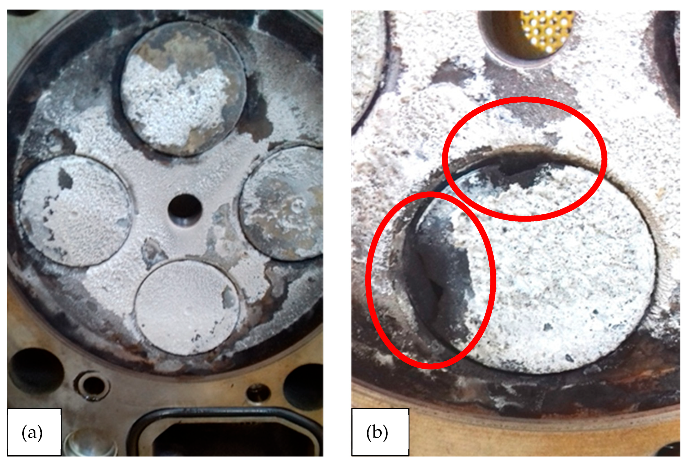
  • Exceeding the coolant temperature of the low-temperature circuit in June 2022 (Figure 8).
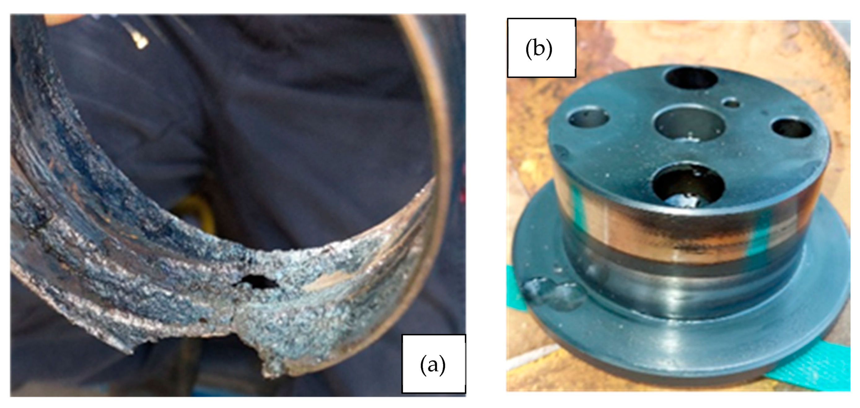
The excessive increase in coolant temperature was a consequence of the loss of tightness of the exhaust valves, resulting from their thermal overload and the burning of the working surfaces of the valve heads and seats, which resulted in an increased heat flow to the cylinder head and cooling system.
  • Pressure loss in the main lubrication system of the internal combustion engine in October 2022 (Figure 9).
Figure 9. Cause of lubrication system failure: (a) damaged main bearing shell, (b) main crankshaft bearing journal damage.
Energies 19 01566 g009
The oil pressure loss was caused by damage to the main bearing shell.
Up to that point and the pressure loss fault, the internal combustion engine had operated for 75,000 mh, which is why the cogeneration system underwent a comprehensive repair.
After the major repair, the cogeneration system was started up in January, maintaining the technological regime of its loading and oil change. Full load was achieved in February 2023 and the cogeneration system achieved an electrical power output of 449–450 kW, with a power factor close to unity and improved biogas parameters. During the operation of the combustion engine, a 4.5-fold exceedance of the engine oil consumption above the limit specified by the manufacturer was recorded.
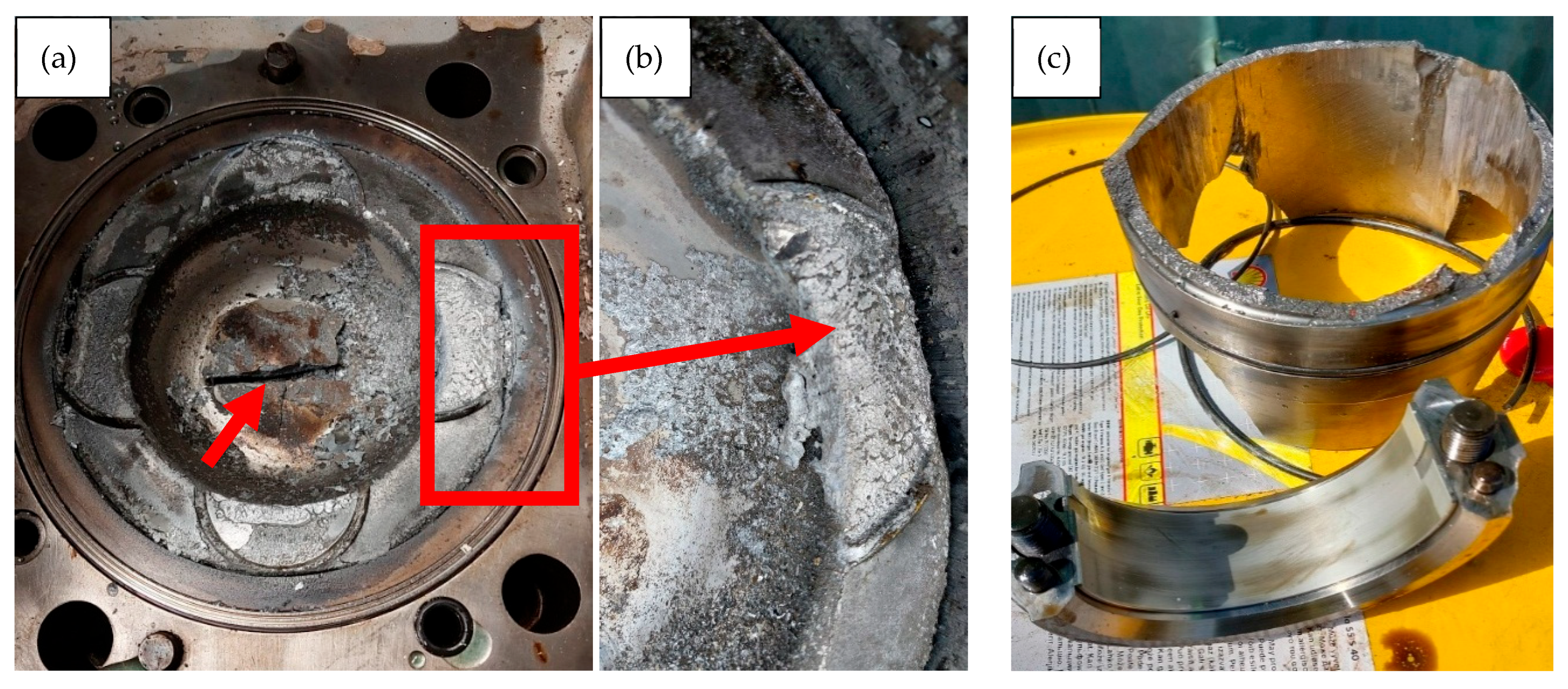
After another three months of operation and approximately 2500 h of work, the combustion engine was damaged as a result of piston seizure in cylinder no. 3 (Figure 10).
The breakdown caused by the piston seizing in the cylinder included a wider range of damage, starting with the destruction of the sleeve surface, cracks in the sleeve, damage to the cylinder head and valve system components, as well as cracks in the engine block. As a result of the temperature increase, the adjacent cylinders 2 and 4 were also damaged.
An analysis of data from the control system from the period prior to the failure showed elevated temperatures in the area of cylinders 2–4, up to a maximum of 50 °C in relation to the other cylinders, but without exceeding the recommended values. During the dismantling of the combustion engine, damage was identified to the lower edge of the flexible valve seal in the area where the ring is seated on the valve stem guide sleeve in the cylinder head. This type of damage leads to a loss of tightness in the area of the valve stem guide and intensive oil ingress into the combustion chamber. This promotes carbon deposits on the valve seat and stem and disrupts heat exchange conditions. Usually, prolonged operation under such conditions leads to local overheating of the valve seats, a decrease in material strength and, consequently, damage to the valve in the cylinder head. However, this did not happen in this case, as this component was not damaged. The variable temperature of the combustible mixture supply deviated from stable operating conditions but was within the limits permitted by the manufacturer.

5. Damage Analysis and Preventive Recommendations

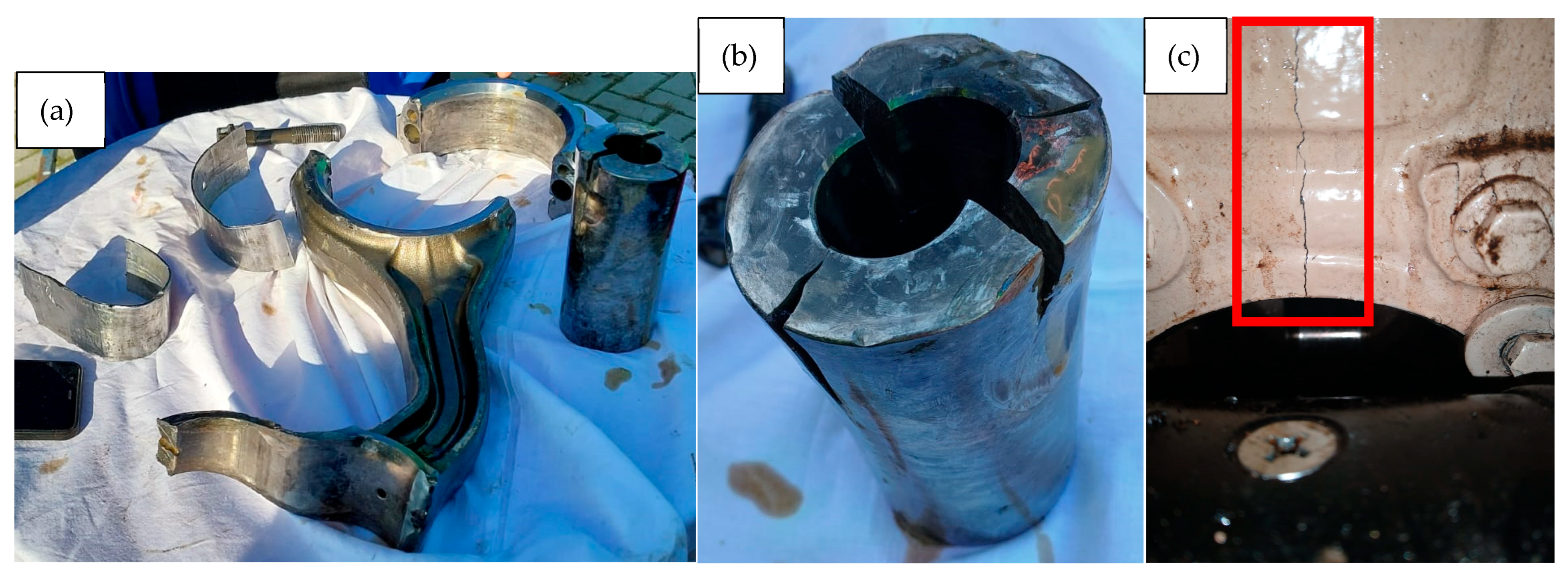
Despite monitoring combustion parameters and regular engine oil tests, as well as performing maintenance, the operation of cogeneration systems at full power is associated with the possibility of failure. In the case of the first failure of the cogeneration system, it was characterized by a significant number of hours worked by the system, but under partial load. In the case of the second failure (Figure 11), after a major repair of the cogeneration system, it is possible to clearly identify the damaged component in the form of a seized piston in the cylinder no. 3. The seizure was caused by increased temperature in the combustion chamber, which can be inferred from the melted piston and lack of lubrication in the piston-cylinder system. However, the remaining cylinders 1, 5–8 show no lack of lubrication. Also, the bearing shell on the connecting rod foot of the cylinder no. 3 showed no signs of wear. The broken spring of the valve stem guide seal ring could not have caused the piston seizure or such excessive engine oil consumption. The cause of the failure cannot be attributed to the long period of operation and the quality of the biogas, as both the combustion engine had undergone a major overhaul and the biogas field had been revitalized.
The failure was the result of a complex interaction of factors causing an increase in temperature in the high-temperature system, with a sudden rise in temperature leading to damage to the crank-piston system. The temperature increase was so intense that the combustion engine control system did not have time to shut down the control.
Based on the analysis of operational problems, the following recommendations should be implemented in the operation process (Table 2):
During the running-in phase, the engine operated at partial load, with power of 250 kW. The first engine oil change was carried out after 250 h and subsequent changes every 500 h. After 2000 h of operation, the power was increased to 400 kW and the system continues to operate at this power to this day. Downtime lasts only 5 h during oil changes and 10 h during inspections performed every 2000 h.

6. Discussion—The Importance of Cogeneration Systems in Eliminating Emissions from Landfills

Although the municipal landfill analyzed operates on the basis of technological solutions characteristic of older generations of facilities of this type, the use of biogas produced in a cogeneration system brings measurable environmental and energy benefits. The utilization of biogas in an internal combustion engine reduces methane emissions in the climate balance and is a highly beneficial solution.
From the point of view of local energy, it is possible to adapt the cogeneration system to the landfill’s biogas production capacity, which allows for the generation of several gigawatt hours of electricity and heat per year, reducing the demand for energy from fossil fuels and increasing the region’s energy security. At the same time, the operation of such installations requires a high level of technical expertise, systematic monitoring of biogas quality and engine condition, and the implementation of solutions to reduce the risk of cogeneration system failure.
In the context of global climate protection efforts, landfill biogas cogeneration systems should be treated as an important element of the circular economy, enabling simultaneous waste utilization, methane emission reduction and energy production from local resources, and must not be neglected [32]. The development of new technologies for CO2 capture and utilization from biogas is very important and further increases the environmental potential, bringing it closer to the concept of low- or even zero-emission renewable energy sources.
From a development perspective, it is worth considering the use of more advanced combustion control systems (knock sensors, vibroacoustic sensors and in-cylinder pressure sensors) with the implementation of automatic control systems using genetic algorithms to predict the composition of the combustible mixture based on historical data in real time. The composition of buildups in the combustion chambers and their influence on exploitation of the engine should also be subjects of future research. As examples of this relation, in [33,34] the authors state, that some silicon compounds, which might form from siloxanes, are highly abrasive materials, causing relevant operation problems. Main pieces of advice for landfill biogas cogeneration systems exploitation are summarized in Table 2.
New requirements for municipal waste landfills in the EU and Poland focus on: a significant reduction in landfilling (max. 10% of municipal waste stream in 2030) with mandatory separation of bio fraction, landfill gas control and stricter operating and monitoring rules. It should be clearly emphasized that the operation of cogeneration systems powered by existing biogas—despite operational problems—remains a key element of low-carbon gas utilization from out-of-operation municipal waste landfills. These observations are consistent with recent findings reported in the literature on bio-gas-based cogeneration systems [14,20,24].

Author Contributions

Conceptualization, K.H. and J.M.; Methodology, A.B., M.G., P.S. and K.C.; Validation, P.S. and K.C.; Investigation, K.H., J.M., A.B., M.G., P.S., K.C., S.W., A.K., M.M. and M.O.; Writing–original draft, K.H., J.M., A.B., M.G., P.S., K.C. and M.O.; Visualization, K.H., J.M., A.B., M.G., P.S., K.C. and M.O. All authors have read and agreed to the published version of the manuscript.

Funding

This research received no external funding.

Data Availability Statement

The original contributions presented in this study are included in the article. Further inquiries can be directed to the corresponding author.

Conflicts of Interest

Author P.S. was employed by Municipal Services in Opole Ltd. during conduction of this study. All authors declare that the research was conducted in the absence of any commercial or financial relationships that could be construed as potential conflicts of interest.

Abbreviations

The following abbreviations are used in this manuscript:
CCSCarbon Capture and Storage
CCUCarbon Capture and Utilization
GHGGreenhouse gas
GWPGlobal Warming Potential
HTHigh Temperature
LTLow Temperature
MNMethane Number
TANTotal Acid Number
TBNTotal Base Number
WuLower Calorific Value
VOCVolatile Organic Compounds

References

  1. Ryckebosch, E.; Drouillon, M.; Vervaeren, H. Techniques for transformation of biogas to biomethane. Biomass Bioenergy 2011, 35, 1633–1645. [Google Scholar] [CrossRef]
  2. IPCC. AR6 Working Group III: Mitigation of Climate Change; Cambridge University Press: Cambridge, UK, 2023. [Google Scholar]
  3. IEA. Net Zero by 2050—A Roadmap for the Global Energy Sector; IEA: Paris, France, 2021. [Google Scholar]
  4. Velasco, A.; Franco-Morgado, M.; Revah, S.; Arellano-García, L.A.; Manzano-Zavala, M.; González-Sánchez, A. Desulfurization of Biogas from a Closed Landfill under Acidic Conditions Deploying an Iron-Redox Biological Process. ChemEngineering 2019, 3, 71. [Google Scholar] [CrossRef]
  5. Torres-Herrera, S.; Palomares-Cortés, J.; González-Cortés, J.J.; Cubides-Páez, D.F.; Gamisans, X.; Cantero, D.; Ramírez, M. Long-term performance and operational factors of a pilot-scale bioscrubber for landfill biogas desulfurization. J. Clean. Prod. 2025, 534, 147100. [Google Scholar] [CrossRef]
  6. Stasiak, P. Analiza przyczyn usterki agregatu kogeneracyjnego PERKINS HE-EC-505/541—PG505-B i sposoby jej zapobiegania (Analysis of the causes of the PERKINS HE-EC-505/541—PG505-B cogeneration unit failure and ways to prevent it). Presented at the XXXVII Konferencja Problemy Rozwoju Maszyn Roboczych (37th Conference on Problems of Working Machine Development), Cedzynia, Poland, 28 February–3 March 2023. [Google Scholar]
  7. Moseman, A.; Trancik, J. Why Do We Compare Methane To Carbon Dioxide over a 100-Year Timeframe? Are We Underrating the Importnce of Methane Emissions? Ask MIT Climate. 2025. Available online: https://climate.mit.edu/ask-mit/why-do-we-compare-methane-carbon-dioxide-over-100-year-timeframe-are-we-underrating (accessed on 15 January 2025).
  8. Konkol, I.; Cebula, J.; Świerczek, L.; Piechaczek-Wereszczyńska, M.; Cenian, A. Biogas Pollution and Mineral Deposits Formed on the Elements of Landfill Gas Engines. Materials 2022, 15, 2408. [Google Scholar] [CrossRef] [PubMed]
  9. Dogniaux, M.; Maasakkers, J.D.; Girard, M.; Jervis, D.; McKeever, J.; Schuit, B.J.; Sharma, S.; Lopez-Noreña, A.; Varon, D.J.; Aben, I. Global satellite survey reveals uncertainty in landfill methane emissions. Nature 2025, 647, 397–402. [Google Scholar] [CrossRef]
  10. Selenius, M.; Ruokolainen, J.; Riikonen, J.; Rantanen, J.; Näkki, S.; Lehto, V.P.; Hyttinen, M. Removing siloxanes and hydrogen sulfide from landfill gases with biochar and activated carbon filters. Waste Manag. 2023, 167, 31–38. [Google Scholar] [CrossRef]
  11. European Environment Agency. Methane Emissions in the EU: The Key to Immediate Action on Climate Change; European Environment Agency: Copenhagen, Denmark, 2022; pp. 1–24. [Google Scholar]
  12. Schweigkofler, M.; Niessner, R. Removal of siloxanes in biogases. J. Hazard. Mater. 2001, 83, 183–196. [Google Scholar] [CrossRef]
  13. Onovwiona, H.I.; Ugursal, V.I. Residential cogeneration systems: Review of the current technology. Renew. Sustain. Energy Rev. 2006, 10, 389–431. [Google Scholar] [CrossRef]
  14. Pinheiro, J.P.; Camiloti, P.R.; Sauer, I.L.; Mady, C.E.K. Exergy Analysis of a Biogas Plant for Municipal Solid Waste Treatment and Energy Cogeneration. Energies 2025, 18, 2804. [Google Scholar] [CrossRef]
  15. Molina, P.; Vascello, G.; Belaustegui, E.; Agapova, A.; Dekker, H.; Lefas, S.; Damaisin, M.; Ghigo, E.; Primmer, N.; Friedman, L.; et al. Biogenic CO2 from Biogases; EBA: Brussels, Belgium, 2025. [Google Scholar]
  16. Klimek, P. Landfill Gas to Energy Projects in Poland. In Proceedings of the Global Methane Initiative All-Partnership Meeting, Krakow, Poland, 12–14 October 2011. [Google Scholar]
  17. Basta, E.; Szewczyk, P. The Use of Methane from Landfill Gas to Generate Energy and its Management at the Plant as a Way to Reduce Climate Change. Rocz. Ochr. Sr. 2024, 26, 236–250. [Google Scholar] [CrossRef]
  18. Ciuła, J.; Generowicz, A.; Gaska, K.; Gronba-Chyła, A. Efficiency Analysis of the Generation of Energy in a Biogas CHP System and its Management in a Waste Landfill—Case Study. J. Ecol. Eng. 2022, 23, 143–156. [Google Scholar] [CrossRef]
  19. Piaskowska-Silarska, M. Opportunities to use landfill gas in Poland. Polityka Energetyczna—Energy Policy J. 2013, 16, 171–179. [Google Scholar]
  20. Ciuła, J.; Kowalski, S.; Generowicz, A.; Barbusiński, K.; Matuszak, Z.; Gaska, K. Analysis of Energy Generation Efficiency and Reliability of a Cogeneration Unit Powered by Biogas. Energies 2023, 16, 2180. [Google Scholar] [CrossRef]
  21. Statistics Poland. Environment 2025; Statistics Poland: Warsaw, Poland, 2025. [Google Scholar]
  22. Chicco, G.; Mancarella, P. Distributed multi-generation: A comprehensive view. Renew. Sustain. Energy Rev. 2009, 13, 535–551. [Google Scholar] [CrossRef]
  23. Kaplan, P.O.; DeCarolis, J.; Thorneloe, S. Is It Better To Burn or Bury Waste for Clean Electricity Generation? Environ. Sci. Technol. 2009, 43, 1711–1717. [Google Scholar] [CrossRef]
  24. Ciuła, J.; Wiewiórska, I.; Banaś, M.; Pająk, T.; Szewczyk, P. Balance and Energy Use of Biogas in Poland: Prospects and Directions of Development for the Circular Economy. Energies 2023, 16, 3910. [Google Scholar] [CrossRef]
  25. Nyamukamba, P.; Mukumba, P.; Chikukwa, E.S.; Makaka, G. Biogas upgrading approaches with special focus on siloxane removal—A review. Energies 2020, 13, 6088. [Google Scholar] [CrossRef]
  26. Torres-Herrera, S.; Palomares-Cortés, J.; González-Cortés, J.J.; Cubides-Páez, D.F.; Gamisans, X.; Cantero, D.; Ramírez, M. Biodesulfurization of landfill biogas by a pilot-scale bioscrubber: Operational limits and microbial analysis. Environ. Res. 2024, 246, 118164. [Google Scholar] [CrossRef] [PubMed]
  27. Bieniek, A.; Mamala, J.; Graba, M.; Prażnowski, K.; Śmieja, M.; Wereszczyński, D. Application of biogas to supply the high compression ratio engine. Combust. Engines 2019, 179, 40–46. [Google Scholar] [CrossRef]
  28. Miltner, M.; Makaruk, A.; Harasek, M. Review on available biogas upgrading technologies and innovations towards advanced solutions. J. Clean. Prod. 2017, 161, 1329–1337. [Google Scholar] [CrossRef]
  29. Totten, G.E.; Bruce, R.W. Handbook of Lubrication and Tribology | PDF | Wear | Friction. 2006. Available online: https://pdfcoffee.com/qdownload/handbook-of-lubrication-and-tribology-pdf-free.html (accessed on 20 February 2026).
  30. Carbon Intensity of the Power Sector in Poland from 2000 to 2023. 2024. Available online: https://www.Statista.Com/Statistics/1290449/Carbon-Intensity-Power-Sector-Poland/ (accessed on 15 January 2026).
  31. Greenhouse Gas Emission Intensity of Electricity Generation in Europe. Indicators. European Environment Agency (EEA). 2025. Available online: https://www.eea.europa.eu/en/analysis/indicators/greenhouse-gas-emission-intensity-of-1 (accessed on 24 February 2026).
  32. Scarlat, N.; Dallemand, J.-F.; Fahl, F. Biogas: Developments and perspectives in Europe. Renew. Energy 2018, 129, 457–472. [Google Scholar] [CrossRef]
  33. Konkol, I.; Cebula, J.; Bohdziewicz, J.; Piotrowski, K.; Sakiewicz, P.; Piechaczek-Wereszczyńska, M.; Cenian, A. Mineral Deposit Formation in Gas Engines during Combustion of Biogas from Landfills and Municipal WWTP. Ecol. Chem. Eng. S 2020, 27, 347–356. [Google Scholar] [CrossRef]
  34. Stanuch, I.; Sozańska, M.; Biegańska, J.; Cebula, J.; Nowak, J. Fluctuations of the elemental composition in the layers of mineral deposits formed on the elements of biogas engines. Sci. Rep. 2020, 10, 4244. [Google Scholar] [CrossRef] [PubMed]
Figure 1. Technological diagram of a cogeneration system at the landfill site [6]: rz. Odra—Odra River, DO—leachate drainage, DWP—groundwater drainage, FI—isolation membrane, G—power generator (3 × 400 V/50 Hz/505 kW), IRO—leachate infiltration installation, KA—generator set container, KP—connection container, KSIP—suction and flare container, LSN—medium-voltage transmission line (3 × 15 kV), OB—battery-type condensate drain, OK—municipal waste, P—flare, PO—leachate pumping station, PWC—clean-water pumping station, SD—suction-blower, SN—drive engine (526 kW/1500 rpm), SO—gas extraction wells (40 pcs.), STR—transformer substation (0.4/15 kV/630 kVA), UCH—generator set cooling system, ZA—generator set valve, ZO—leachate tank, ZP—flare valve, ZRS—well control valves.
Energies 19 01566 g001
Figure 2. Satellite observations of methane plumes at urban (TROPOMI: (a,c,e,l)) and facility scales (GHGSat: (b,d,fh,j,k,m)) for selected cities worldwide. (i) world map with marked locations of research (black arrows). White dots indicate the plume source points identified by GHGSat. Black contours delineate the boundaries of the landfill sites. Reproduced from Dogniaux et al. [9], licensed under CC BY 4.0. Wind direction/speed from ERA5. Background Sentinel-2 imagery (2022). Scale bars: 50 km (a,c,e,l) and 1 km (b,d,fh,j,k,m,n,o).
Energies 19 01566 g002
Figure 3. Trends and changes in CH4 emissions from waste management [11].
Energies 19 01566 g003
Figure 4. Components of the energy cogeneration system at the landfill site: (a,b)—view of the cogeneration system, (c)—flare, (d)—measuring system, (e)—suction-blower.
Energies 19 01566 g004
Figure 6. Biogas wells building process at the landfill site: (a) well drilling, (b) perforated pipe insertion, (c) material used for gap filling, (d) well connection to the collector, (e) filling the gap separating the pipe from the deposed waste.
Energies 19 01566 g006
Figure 7. Biogas treatment: (a)—biogas flow rotameters, (b)—iron hydroxide (SULFAX), (c)—example measurement of the chemical composition of unconditioned biogas.
Energies 19 01566 g007
Figure 8. View on the cylinder head from the engine block side: (a) siloxane deposits, (b) burnt-out exhaust valve and its seat marked with red ellipse.
Energies 19 01566 g008
Figure 10. Damaged components of the crankshaft–piston system of an internal combustion engine: (a) piston crown, (b) piston crown closeup, (c) cylinder sleve; red arrow in (a) shows a crack in the piston crown; the red box in (a) shows the part of the piston crown enlarged in (b).
Energies 19 01566 g010
Figure 11. Example parts damaged from failure in 2025: (a) connecting rod and its bearings, (b) piston pin, (c) crack in the cylinder block (marked with red box).
Energies 19 01566 g011
Table 1. Parameters of biogas supplying the cogeneration system.
ParameterValueUnit
Density1.158kg/m3
Net Calorific Value17,640kJ/Nm3
Net Calorific Value4.900kWh/Nm3
Gross Calorific Value19,634kJ/Nm3
Gross Calorific Value5.454kWh/Nm3
Wobbe’s index5.621kWh/Nm3
Methane number135-
Table 2. List of recommendations to be implemented.
Recommendation FieldDescription
Fuel quality: biogas testing.Despite detailed monitoring of the biogas composition during operation, at least twice a year and after each upgrade of the municipal waste landfill, conduct full laboratory tests of the biogas properties.
Exploitation: restart after downtime.Gradually increase the load after prolonged downtime to limit thermal shock.
Exploitation: shut down.Avoid sudden stops of a heated engine, which generate unfavorable temperature gradients in the cylinder head and cylinders.
Exploitation: temperature monitoringClose monitoring of cylinder temperatures and rapid response to deviations from nominal values by the control system, up to and including shutdown of the cogeneration system.
Motor oil: intervals and analyzes.Shortening oil change intervals and extended oil analysis (TBN, Si, Na, Fe, Cu, TAN and water) as a predictive tool.
Motor oil: diagnostics in case of increase in oil consumption.In the event of a sudden increase in oil consumption—immediate mechanical diagnostics (compression pressure measurement, endoscopy and valve seal inspection).
Construction: mixture regulation.Implementation of real-time automatic combustion engine parameter control systems using genetic algorithms with mixture composition prediction based on historical data.
Disclaimer/Publisher’s Note: The statements, opinions and data contained in all publications are solely those of the individual author(s) and contributor(s) and not of MDPI and/or the editor(s). MDPI and/or the editor(s) disclaim responsibility for any injury to people or property resulting from any ideas, methods, instructions or products referred to in the content.