Article

Acoustic–Electrokinetic Coupling for Low-Frequency Energy Harvesting: A Theoretical Framework and Numerical Validation of the Acoustic Baroionic Harvester


Facultad de Ingeniaría en Ciencias Aplicadas FICA, Universidad Técnica del Norte, Ibarra 100101, Ecuador
*
Author to whom correspondence should be addressed.
Energies 2026, 19(5), 1150; https://doi.org/10.3390/en19051150
Submission received: 14 November 2025 / Revised: 15 December 2025 / Accepted: 26 December 2025 / Published: 25 February 2026
(This article belongs to the Special Issue Advances in Energy Harvesting Systems)

Abstract

Low-frequency acoustic fields—common in ventilation ducts, building façades, and industrial infrastructure—remain an underutilized source for ambient energy harvesting, particularly in humid environments where conventional contact-based or mechanically resonant harvesters may degrade over time. This study introduces a theoretical framework for converting acoustic pressure oscillations into electrical power through acoustic–electrokinetic coupling and proposes the Acoustic Baroionic Harvester (ABH) as a solid-state concept combining a Helmholtz resonator with a charged nanoporous membrane. The model is derived from coupled electrokinetic and fluid-mechanical governing relations, leading to closed-form expressions for the open-circuit voltage, internal electrokinetic resistance, and maximum deliverable power as functions of membrane surface charge, electrolyte properties, pore geometry, and resonance-induced pressure amplification. Numerical simulations are performed to validate the analytical scaling laws and to determine operating regimes that maximize power transfer to an external load. Under representative low-frequency acoustic excitation, the ABH predicts open-circuit voltages on the order of tens of millivolts and maximum power densities in the sub-microwatt-per-square-centimeter range. A compact CAD conceptual design tuned to approximately 120 Hz with a moderate resonance quality factor supports the feasibility of practical integration. The proposed approach enables micro-power generation from persistent low-frequency acoustic sources and provides a physically grounded pathway for self-powered sensing applications in built and industrial environments.

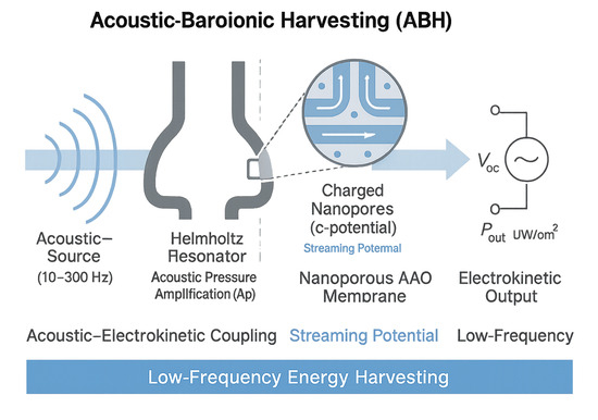
Graphical Abstract

1. Introduction

1.1. Context of Energy Harvesting Technologies

The rapid expansion of the Internet of Things (IoT), wireless sensor networks, and distributed monitoring has intensified the need for maintenance-free, ultra-low-power energy sources capable of long-term autonomous operation. Ambient energy harvesting has therefore become a key research direction, spanning piezoelectric, triboelectric, electromagnetic, thermoelectric, and electrokinetic transduction. Recent reviews consistently conclude that no single mechanism is universally optimal; rather, each approach occupies a niche defined by excitation frequency, environmental robustness, integration complexity, and achievable power density [1,2].
Piezoelectric harvesters convert mechanical strain into electrical charge and remain dominant in vibration-based deployments. To address low-frequency excitations, recent designs use strategies such as magnetic plucking and inertial amplification to broaden the effective bandwidth and up-convert slow motion into higher-frequency piezoelectric response. Representative examples include magnetic-plucking architectures and ultra-low-frequency inertial systems that can reach tens of microwatts near 1 Hz under favorable mechanical matching [3,4], alongside broader reviews covering device architectures and interface circuits for self-powered systems [5]. However, piezoelectric performance is often constrained by resonance narrowness, fatigue, and sensitivity to environmental conditions, which becomes evident in practical fluid-driven cases where efficiency strongly depends on mechanical coupling and flow regime [6].
Triboelectric nanogenerators (TENGs) rely on contact electrification and electrostatic induction and have gained attention due to their material flexibility and broad application range. Recent reviews synthesize progress in working modes and materials, including structural monitoring and blue energy systems [7,8]. At the same time, state-of-the-art studies emphasize persistent limitations related to humidity sensitivity, surface contamination, and long-term mechanical wear, particularly in harsh environments [9,10]. Wearable and skin-contact TENGs further highlight the durability–flexibility trade-off under sweat-rich conditions [11]. These constraints are also supported by bibliometric and systematic evidence identifying material stability and contact fatigue as dominant bottlenecks for large-scale deployment [12], although low-cost implementations demonstrate that meaningful edge power is achievable when environmental conditions are favorable [13].
Electromagnetic energy harvesters convert relative motion between magnets and coils into electrical power and are particularly attractive for moderate to ultra-low-frequency excitations. Reviews emphasize their effectiveness for low-frequency kinetic energy capture, while noting typical requirements for moving parts and larger form factors [14]. Recent rotating and pendulum-type inertial designs can operate efficiently well below 1 Hz, which is relevant for human motion or slow structural dynamics [15,16]. Nevertheless, the reliance on mechanical assemblies and bearings may increase wear and maintenance burden in dusty, humid, or inaccessible infrastructures.
Thermoelectric generators (TEGs) exploit temperature gradients via the Seebeck effect and are fully solid-state, making them reliable in harsh or high-temperature settings. Reviews and recent demonstrations show that TEG-powered IoT nodes can support industrial monitoring and wireless transmission when sufficient waste heat exists, especially when power management is optimized [17,18,19]. Low-cost implementations using Peltier-based modules further illustrate feasibility in domestic and industrial contexts [20]. Yet, in thermally stable environments (e.g., indoor air networks, building façades without strong solar gradients), the available Δ T is often too small to supply more than a few microwatts without large heat exchangers.
Electrokinetic and streaming-potential systems represent a distinct pathway, converting pressure-driven ionic transport in charged pores into electrical potential and current. Recent theoretical and numerical studies have clarified efficiency limits under steady and oscillatory conditions, including nanofluidic and non-Newtonian regimes [21,22]. Related work on moisture- and evaporation-driven electricity generation indicates that nanoporous structures with controlled surface charge—such as anodic aluminum oxide (AAO)—can sustain measurable streaming potentials under moderate pressure drops and modest flow rates. This body of evidence motivates coupling electrokinetic conversion with ambient pressure oscillations.
Acoustic and barometrically driven harvesters intersect these domains. Piezoelectric membrane-based and metamaterial-assisted acoustic harvesters can achieve high energy densities in the audio band, often requiring elevated sound pressure levels and mechanically complex configurations [23,24,25]. Reviews of low-frequency kinetic and acoustic energy harvesting conclude that efficient conversion below ~300 Hz remains challenging, particularly in humid and structurally constrained environments such as ventilation ducts, window frames, and industrial piping.

1.2. The Unexplored Potential of Acoustic–Electrokinetic Coupling

Electrokinetic phenomena arise when an electrolyte flows through charged nano- or microchannels, where the interaction between the electric double layer (EDL) and pressure-driven flow produces an electrical response. In the streaming-potential configuration, a pressure gradient drives ionic transport along charged walls, generating a measurable voltage between the channel ends. Classical analyses show that the streaming response scales with interfacial charge (zeta potential), dielectric permittivity, viscosity, conductivity, and channel geometry, and can reach non-negligible conversion efficiencies under optimized conditions [26,27,28].
Recent theoretical and numerical studies have expanded electrokinetic energy conversion (EKEC) models to non-ideal regimes, including viscoelasticity, nanofluidic effects, and complex geometries, demonstrating strong sensitivity to rheology, EDL thickness, and the temporal structure of the driving pressure [22]. Extensions to porous microtubes and pressure-dependent viscosity further indicate that properly designed charged membranes can sustain comparatively high electrokinetic efficiencies under moderate pressure drops [22,29,30]. Importantly, centimeter-scale feasibility has been experimentally demonstrated in pressure-driven streaming-potential generators based on porous media, which produce measurable voltages under realistic flow conditions [31].
Despite this progress, streaming potentials remain underutilized for ambient energy harvesting because most EKEC studies focus on steady, pump-driven microfluidics aimed at fundamental limits rather than self-contained harvesters [32]. In parallel, nanofluidic and osmotic energy conversion has shown that engineered pores and surface charge can approach high theoretical efficiencies, yet the driving force is typically osmotic rather than acoustic or barometric pressure oscillations [33,34]. As a result, while the electrokinetic toolbox for converting pressure gradients into electrical output is well developed, the pressure source is commonly externally supplied rather than harvested from ambient fields.
In contrast, acoustic harvesting has extensively used Helmholtz resonators as passive pressure amplifiers, largely coupled to piezoelectric, triboelectric, or magnetoelastic transducers. Helmholtz-based triboelectric systems and resonant barriers have been proposed to broaden bandwidth and enhance low-frequency conversion from environmental sound and traffic noise [35,36,37]. Similarly, Helmholtz–piezoelectric devices have reported substantial efficiency gains in the 50–300 Hz range, supported by experiments and finite-element modeling [38,39], while membrane-type magnetoelastic generators demonstrate acoustic-to-electrical conversion at higher frequencies suitable for sensing [40]. However, these approaches rely on mechanical–electrical transduction; the EDL-driven streaming-potential mechanism is typically not modeled as the primary conversion pathway.
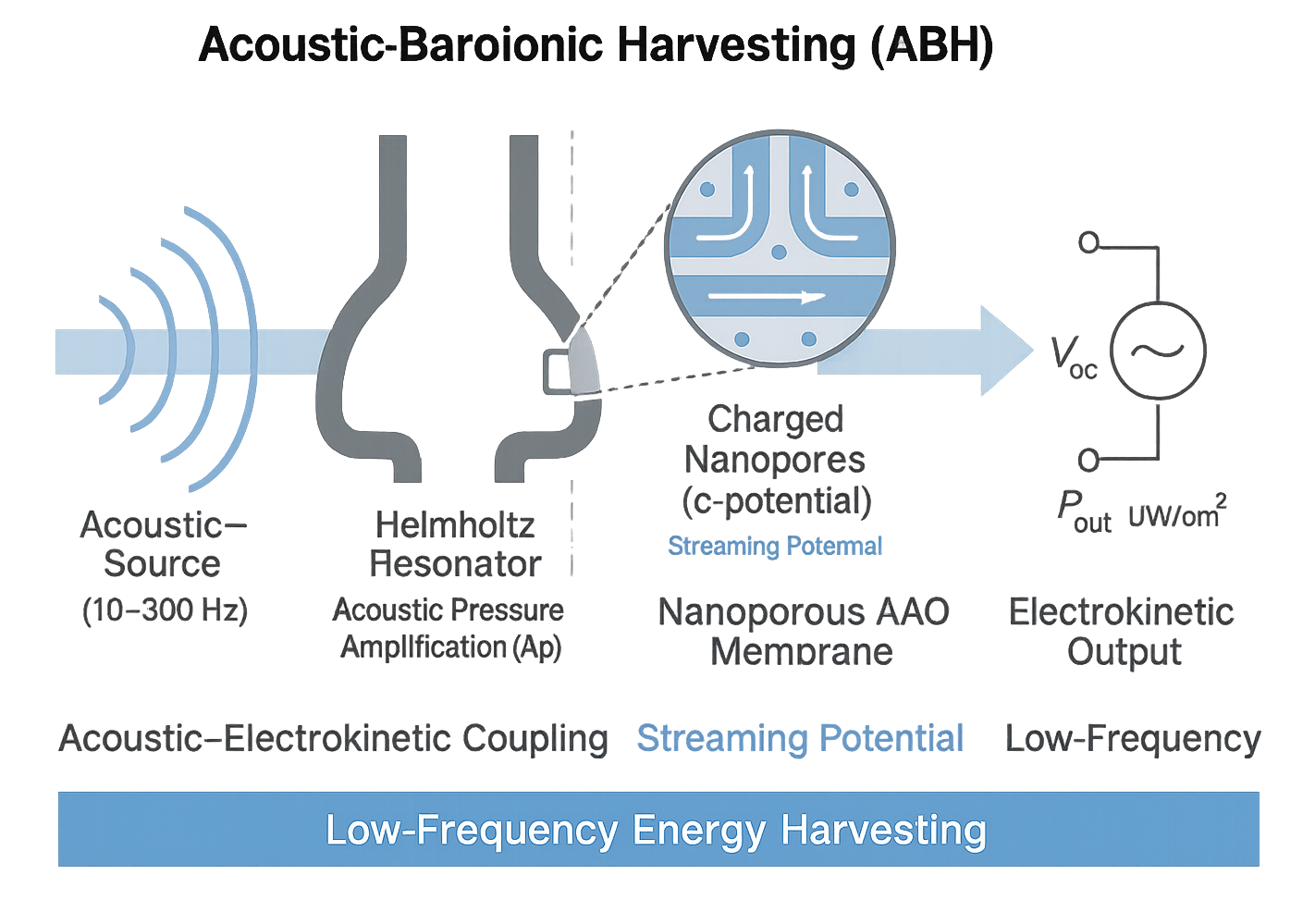
This motivates the central idea of the present work: acoustic resonance can serve as a passive, frequency-selective pressure pump that periodically drives electrolyte through charged nanopores, producing streaming potential and current according to electrokinetic relations. In this framework, the Helmholtz cavity–neck system provides macroscopic pressure amplification in the low-frequency band, while a nanoporous membrane (e.g., AAO) provides the electrokinetic interface that converts the amplified pressure drop into baroionic charge transport. By explicitly modeling the resonator as a frequency-selective pressure source and the membrane as an electrokinetic transducer, the proposed Acoustic Baroionic Harvester (ABH) bridges two previously separate research streams and suggests a durable alternative for humidity- and dust-prone environments such as heating, ventilation, and air-conditioning ducts, window frames, and industrial enclosures, while preserving the established acoustic design tunability used in resonator-based harvesting systems.

1.3. Objectives

The present work introduces a novel framework for acoustic–electrokinetic energy harvesting, grounded in the deliberate coupling between Helmholtz acoustic resonance and streaming-potential generation in charged nanoporous membranes. While electrokinetic energy conversion and acoustic resonance have been investigated independently, their integration as a unified transduction mechanism remains unexplored. This study aims to formally define, model, and evaluate such a system from first principles.
The objectives of this article are threefold:
  • Propose a new physical–mathematical model for an Acoustic Baroionic Harvester (ABH). We introduce a rigorous derivation that integrates the linearized Navier–Stokes equations, Poisson–Boltzmann theory, and the Helmholtz–Smoluchowski streaming-potential relation with the frequency-domain acoustic response of a Helmholtz resonator. The resulting model provides closed-form expressions for the open-circuit voltage V o c , internal electrokinetic resistance R i n t , frequency-dependent pressure amplification Δ p ( f ) , and harvested power P m a x ( f ) . The framework highlights the coupling coefficient K = ζ ε / ( η σ ) as a key electrokinetic parameter, and the quality factor Q as the main acoustic gain factor, enabling a systematic exploration of design trade-offs.
  • Numerically validate the theoretical model using realistic environmental and material parameters. Parameter sweeps covering representative zeta potentials ζ = 30 – 70   mV , conductivities σ = 0.1 – 10   mS / m , and acoustic conditions (10–300 Hz, Q = 20 – 100 ) were implemented in Python 3.13. These simulations produced characteristic curves—such as P ( f ) , P ( σ ) , and P ( Q ) —that confirm the analytical scaling laws and reveal optimal operating regimes. The computed power densities (0.1–1 µW/cm2) and open-circuit voltages (40–100 mV/cm2) fall within ranges previously reported for streaming-potential devices operating under moderate pressure drops, supporting the feasibility of the proposed design.
  • Identify and analyze potential application scenarios. Based on measured acoustic environments in ventilation systems, building façades exposed to urban traffic, and industrial infrastructures with strong low-frequency or infrasonic components, we outline deployment opportunities where the ABH can function as a self-sustaining micro-power source. The device’s purely passive acoustic front end and solid-state electrokinetic conversion make it particularly suitable for integration into HVAC ducts, window frames, and structural monitoring systems. Its compatibility with ultra-low-power IoT platforms further positions the ABH as a candidate for continuous environmental sensing without external power or battery replacement.

1.4. Physical Context

1.4.1. Electrokinetic Fundamentals

In a charged-solid/liquid interface, the formation of an electrical double layer (EDL) governs the electrokinetic phenomena that are exploited in streaming potential energy harvesting. At the solid boundary, the chemical or physical adsorption of ions produces a surface charge. This surface charge is balanced by a closely bound layer of counter-ions (the Stern layer) and a more diffuse layer of mobile ions (the diffuse layer). The potential at the shear plane (the plane separating the mobile fluid from the immobile layer), known as the zeta-potential ζ, plays a pivotal role in the coupling between fluid motion and electric current [41,42].
From a continuum perspective, the EDL may be described by the Poisson–Boltzmann (P–B) equation, which for a symmetric electrolyte of valence z reads
∇ 2 ψ = − 1 ε ∑ i z i e   c i 0 e x p ( − z i e ψ k B T )
where ψ is the local electrostatic potential, ε the permittivity of the electrolyte, e the elementary charge, c i 0 the bulk ion concentration of species i , k B the Boltzmann constant, and T the temperature. In the limit of small potentials z i e ψ ≪ k B T , it is common to linearize the P–B equation to
∇ 2 ψ = κ 2 ψ , κ − 1 = ε k B T 2 z 2 e 2 c 0
where κ − 1 is the Debye length, characterizing the thickness of the diffuse layer [43].
Meanwhile the fluid motion within a narrow channel or porous medium under a pressure gradient Δ p is governed by the Navier–Stokes equations. Under the assumptions of incompressible Newtonian fluid, steady laminar flow and negligible inertial terms (Reynolds number ≪ 1), the linearized Navier–Stokes equation simplifies to
η ∇ 2 u = ∇ p
with u the velocity field and η the dynamic viscosity of the fluid.
When a pressure-driven flow carries mobile counter-ions within the diffuse layer, an electric current (streaming current) is generated. At steady state in an open-circuit configuration, this streaming current is balanced by a conduction current through the bulk electrolyte until the net current is zero, producing a measurable streaming potential V o c   between the ends of the flow path.
The classical Helmholtz–Smoluchowski equation provides the coupling between the applied pressure drop and the induced streaming potential under the condition of thin EDL ( κ a ≫ 1 , where a is characteristic channel radius) and negligible surface conduction. The relation can be written as
V o c = ζ   ε η   σ   Δ p
where σ is the bulk conductivity of the electrolyte [42].
Correspondingly, the internal resistance of the electrokinetic transducer (for a simple capillary or bundle of channels of length L and equivalent cross-sectional area A e q ) may be approximated as
R i n t = L σ   A e q
And thus the maximum extractable power under matched load conditions is
P m a x = V o c 2 4   R i n t = ( ζ   ε   Δ p ) 2 4   η 2   σ ⋅ A e q L
These expressions form the cornerstone for the theoretical modelling of streaming-potential-based energy harvesters.

1.4.2. Acoustic Resonance Amplification

A resonant cavity of the Helmholtz type can significantly enhance the local sound pressure level (SPL) by exploiting the dynamic coupling between the mass of the air in the neck and the compliance of the air in the cavity. This amplification is a key enabler when coupling acoustic excitation to microfluidic or nanoporous harvesting elements.
Helmholtz Resonator Model and Pressure Gain
For a classical Helmholtz resonator (HR) composed of a cavity of volume V , connected to the ambient by a neck of cross-sectional area A and effective length L e q (including end-correction), the resonant angular frequency ω H   and the resonant frequency f H are given by
ω H = v A V   L e q   , f H = ω H 2 π = c 2 π A V   L e f f
where v is the speed of sound in the medium (typically air).
Several recent works confirm the validity of this formulation in engineered cavities such as metamaterials and energy-harvesting devices [44,45,46,47].
At resonance, the acoustic pressure within the cavity may be amplified relative to the incident pressure p e n v . We may define a pressure gain factor G p
G p = Δ p c a v i t y p e n v
Under idealized (low-loss) conditions, G p scales with the resonator’s quality factor Q , such that
Δ p ≈ Q   p e n v
where Δ p = p c a v i t y − p a m b i e n t . This relation has been employed in the acoustic-energy-harvesting literature to estimate effective pressure amplitudes inside HR systems [48,49].
Quality Factor Q and Effective Frequency Range
The quality factor Q of the resonator quantifies the sharpness of the resonance and is defined by
Q = f H Δ f F W H M
where Δ f   is the full width at half maximum (FWHM) of the resonance frequency band. A higher Q   implies stronger amplification but narrower bandwidth. For acoustic harvesting applications, a trade-off exists: available environmental spectrum vs. cavity tuning. Recent numerical results for HR systems show that tailored cavity geometry may yield Q -values in the dozens to hundreds in the low-frequency (tens to few hundreds of Hertz) range [46,50].
Coupling Between Pressure Field and Hydrodynamic Gradient in Nanoporous Membranes
When the amplified acoustic pressure fluctuation Δ p ( t ) is applied to a porous membrane or channel network, these pressure oscillations induce fluid flow inside the pores (driven by the pressure gradient). Within a simplified one-dimensional pore of length L and cross-sectional area A i , the local pressure gradient is
∇ p ≈ Δ p L
This drives a volumetric flow rate Q v   (by Poiseuille or lubrication approximation), which in turn causes streaming of the mobile ions in the diffuse layer, thereby generating the streaming current. In effect, the acoustic cavity transforms the ambient acoustic perturbation into an elevated static or quasi-static pressure drop across the porous medium.
Thus, the chain of conversion may be conceptualized as
p e n v →     H R     Δ p   →     hydrodynamic   coupling   in   pores     ∇ p   →     electrokinetic   effect     V o c
The amplification due to the resonator therefore directly mitigates the low amplitude of ambient acoustic pressures, improving the downstream electro-hydrodynamic conversion efficiency.
By combining the resonator gain relation Δ p ≈ Q   p e n v with the electrokinetic coupling V o c ∝ Δ p , one obtains
V o c ≈ ζ   ε η   σ   ( Q   p e n v )
which highlights the critical role of both acoustic amplification Q and electrokinetic parameters in the overall voltage output.

1.4.3. Conceptual Coupling Mechanism

In the proposed system, the acoustic–electrokinetic transducer is conceptualized as a two-stage conversion chain: first the amplification of ambient acoustic pressure via a resonant cavity, and second the conversion of this amplified pressure differential into an ionic current (and hence an electrical potential) via the electrokinetic streaming mechanism [51,52]. Accordingly, the entire device may be represented by a Thevenin-equivalent circuit (voltage source + internal resistance) driven by the acoustic input.
Transducer Representation and Thevenin Analogy
Let the externally incident acoustic pressure fluctuation be p e n v ( t ) . After resonator amplification, the internal pressure differential across the porous membrane is
Δ p ( t ) = G p   p e n v ( t )
where G p ≈ Q under near-resonant conditions. The electrokinetic coupling coefficient is defined as
K = ζ   ε η   σ
Accordingly, the open-circuit streaming voltage becomes
V s ( t ) = K   Δ p ( t )
This may be represented in circuit form as a voltage source V   s in series with an internal resistance
R i n t = L σ   A e q
With an external load R L , the output voltage and delivered power are
V o u t ( t ) = R L R L + R i n t   V s ( t ) , P L ( t ) = [ V o u t ( t ) ] 2 R L
Hence, the full chain may be described as
p e n v ( t )   →   resonator   amplification     Δ p ( t )   →   electro-kinetic   coupling     V s ( t )   →   load   matching     P L ( t )
Energy Transfer Between Acoustic Field and Ionic Current
From an energy perspective, the ambient acoustic wave carries an acoustic power flux P a c = p e n v 2 / ( 2 ρ c ) (where ρ   and c are the density and speed of sound of the medium). The resonator concentrates a fraction of this power into the membrane region through the pressure gain G p , such that
Δ p ≈ Q   p e n v
In the porous medium, the pressure gradient ∇ p ≈ Δ p / L drives a volumetric flow rate Q v , which entrains counter-ions and thereby generates a streaming current I s t r . In open circuit, this current is balanced by a conduction current I c o n d , and a steady streaming potential V o c = V s develops. The conversion of mechanical energy (via Δ p ) into electrical energy (via V s and P L ) can thus be quantified by an approximate overall conversion efficiency
η a e ≈ P L P a c   A n e c k
where A n e c k is the effective area over which the acoustic power is delivered. Substituting V s = K   Δ p ≈ K   Q   p e n v and P L ≈ V s 2 / ( 4 R i n t ) (for matched load) yields
η a e ≈ ( K   Q   p e n v ) 2 4   R i n t   ( p e n v 2 / ( 2   ρ   c )   A n e c k ) = K 2   Q 2   2   ρ   c   A n e c k 4   R i n t = K 2   Q 2   ρ   c   A n e c k 2   R i n t
This expression highlights the key dependencies: the electrokinetic coupling coefficient K , the acoustic quality factor Q , the acoustic medium parameters ρ c , the geometry A n e c k , and the internal resistance R i n t .
In effect, the resonator amplifies ambient acoustic fluctuations into a usable Δ p , which is then transduced via ionic motion into an electric potential and power. The coupling chain therefore integrates acoustic physics, fluid mechanics, and electrokinetics in a unified framework.

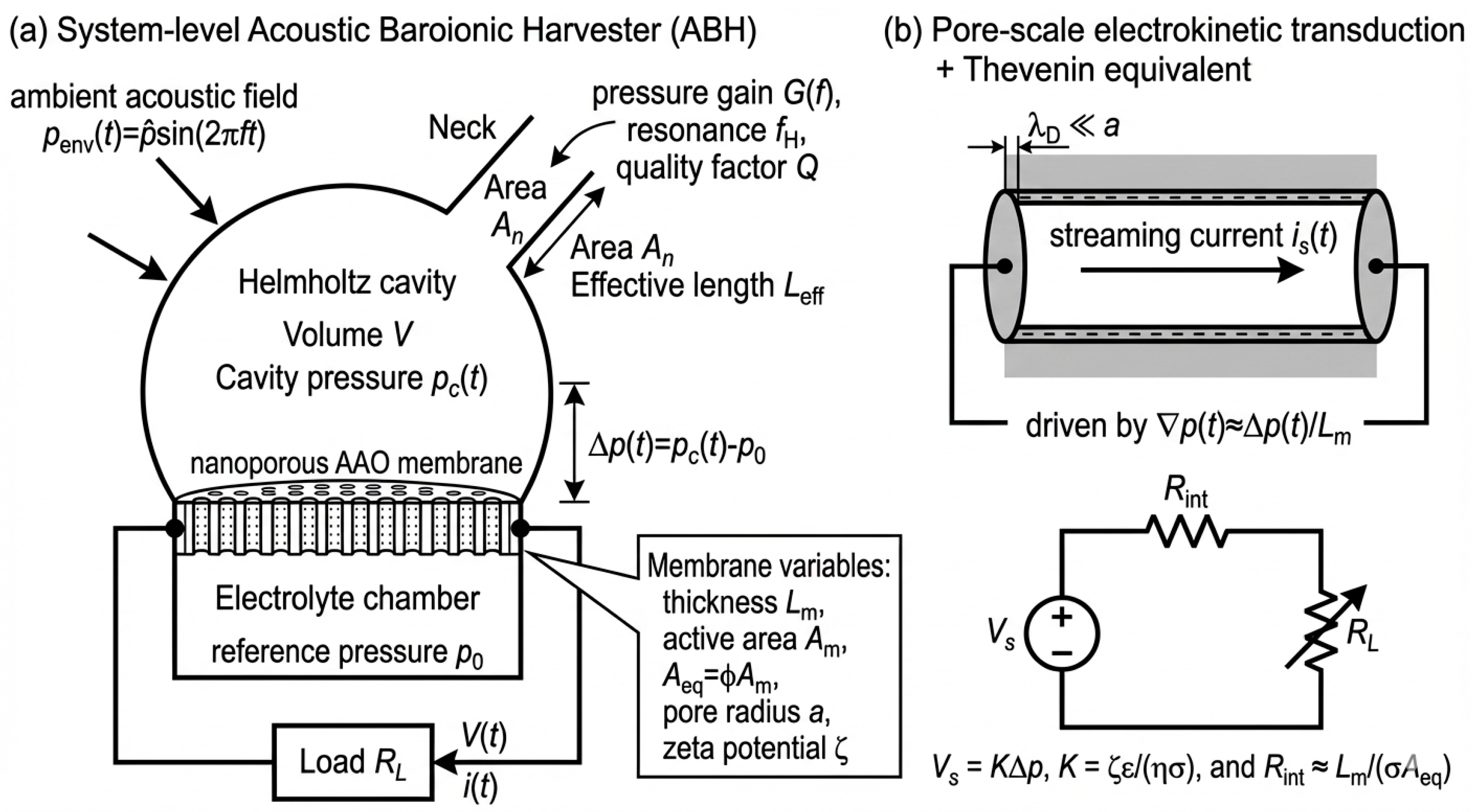
2. Device Concept and Working Principle

The proposed Acoustic Baroionic Harvester (ABH) is a passive, low-frequency energy harvester that couples (i) acoustic pressure amplification by a Helmholtz resonator with (ii) electrokinetic transduction in a charged nanoporous membrane. The device is driven by an ambient acoustic field p e n v ( t ) = p ^ s i n ( 2 π f t ) and uses the resonator transfer function G ( f ) to generate an amplified cavity pressure p c ( t ) . The resulting time-varying pressure drop across the nanoporous membrane is defined as
Δ p ( t ) = p c ( t ) − p 0 ,
where p 0 is the reference pressure on the electrolyte side (e.g., a vented or buffered liquid chamber). The resonator is characterized by its Helmholtz resonance frequency f H and quality factor Q , which together determine both the frequency selectivity and the attainable pressure gain in the operative band.
Electrokinetic conversion occurs when Δ p ( t ) drives electrolyte flow through the membrane’s charged nanopore ensemble (effective area A e q = ϕ A m , membrane thickness L m , pore radius a , porosity ϕ ). Under the thin-EDL approximation ( λ D ≪ a ) , the pressure-driven flow advects excess counter-ions in the electric double layer, producing a streaming current and an associated streaming potential. At the device terminals, the ABH is conveniently represented by a Thevenin equivalent: a pressure-controlled source
V s ( t ) = K   Δ p ( t ) , K = ζ ε η σ ,
In series with an internal electrokinetic resistance approximated by
R i n t ≈ L m σ A e q ,
driving an external load R L . This representation makes explicit the acoustic-to-electric pathway: p e n v ( t ) → p c ( t ) → Δ p ( t ) → V ( t ) , i ( t ) , and directly links design parameters ( V , A n , L e f f , f H , Q , A e q , L m , ζ , ε , η , σ ) to measurable electrical outputs (Figure 1).

3. Methods

3.1. Mathematical Modeling of the ABH

3.1.1. Derivation of the Governing Equations

The proposed ABH system relies on the coupling of fluid-mechanical, electrostatic, and ionic transport phenomena. The governing field equations include the continuity equation for incompressible flow, the linearized Navier–Stokes equation under steady laminar assumptions, and the Poisson (or Poisson–Boltzmann) equation for the electric potential in the electrolyte [53,54].
The continuity equation for an incompressible Newtonian fluid is
∇ ⋅ u = 0
where u is the fluid velocity vector.
Under the assumption of steady laminar flow with negligible inertial terms (Re ≪ 1), the Navier–Stokes equation reduces to the form
η   ∇ 2 u = ∇ p
where η   is the dynamic viscosity and p is the pressure field. To justify the assumptions of incompressible Newtonian behavior, steady laminar flow, and negligible inertia, the characteristic nondimensional numbers are considered. First, compressibility effects are negligible because the acoustic particle velocity in ventilation- or infrastructure-scale environments is typically much smaller than the speed of sound, such that the Mach number M = u / c ≪ 1 . Under these conditions, density variations are second order in M , and the flow through the porous membrane can be treated as incompressible. Second, inertia is negligible inside the nanoporous membrane because the characteristic pore scale a is small and the induced velocities are limited by viscous resistance; thus, the pore-scale Reynolds number R e = ρ u a η remains well below unity in the operating regimes targeted here, implying a Stokes-flow (creeping-flow) limit. This supports the use of the linearized Navier–Stokes equations and the neglect of convective acceleration terms. Finally, because the pressure forcing is oscillatory, the relevant measure of unsteady inertia is the Womersley number α, which compares transient inertia to viscous diffusion across the pore radius. For the low-frequency band of interest and nanopore-scale radii, α ≪ 1 is expected, indicating a quasi-steady regime in which the velocity profile adjusts rapidly compared to the forcing period. Consequently, the leading-order electrokinetic response can be modeled using the thin-EDL approximation and reduced to the Helmholtz–Smoluchowski streaming-potential relation, while higher-order inertial corrections are neglected. Accordingly, the analysis focuses on the regime M ≪ 1 , R e ≪ 1 , and α ≪ 1 , which is consistent with nanopore-scale transport driven by low-frequency pressure oscillations in practical built-environment acoustic settings.
Simultaneously, the electrostatic potential ψ in the electrolyte satisfies the Poisson equation
∇ 2 ψ = − ρ e ε
where ρ e is the local charge density and ε is the permittivity of the medium. In the diffuse layer region, the Poisson–Boltzmann equation may be written (for a symmetric z-valent electrolyte) as
∇ 2 ψ = − 2 z e c 0 ε   s i n h ( z e ψ k B T )  
In the thin-EDL limit ( ∣ z e ψ ∣ ≪ k B T ) , this may be linearized to
∇ 2 ψ = κ 2   ψ
where κ − 1 is the Debye length.
The key coupling arises because the pressure-driven fluid motion entrains mobile counter-ions in the diffuse layer (streaming current), which in open circuit is balanced by a conduction current, leading to a streaming potential V o c . Under the classical assumptions of (i) thin EDL ( κ a ≫ 1 , where a is a characteristic channel radius), (ii) negligible surface conduction and slip, the Helmholtz–Smoluchowski relation applies:
V o c = ζ   ε η   σ   Δ p
where ζ is the zeta-potential at the shear plane, σ is the bulk electrolyte conductivity, and Δ p is the applied static pressure drop along the channel.
For a bundle of N parallel channels or nanopores of total equivalent cross-sectional area A e q and length L , the internal resistance of the electrokinetic transducer is approximated by
R i n t = L σ   A e q
Hence, the maximum extractable power under matched load conditions becomes
P m a x = V o c 2 4   R i n t = ( ζ   ε   Δ p ) 2 4   η 2   σ   A e q L
Since the acoustic resonator amplifies the ambient pressure p e n v ( f )   by a factor related to the resonator’s quality factor Q , the induced pressure differential can be modelled as a function of frequency:
Δ p ( f ) = Q   p e n v   1 1 + Q 2   ( f f H − f H f ) 2
where f H is the resonant acoustic frequency of the Helmholtz cavity.
A full sensitivity analysis is then performed on the primary design parameters: ζ , σ , Q , A e q , and L .

3.1.2. Theoretical Energy Conversion Efficiency

An acoustic-to-electrical conversion efficiency may be defined by comparing the harvested electrical power P o u t ≈ V o c 2 / ( 4   R i n t )   with the incident acoustic power delivered to the neck of the resonator:
η a e = P o u t P a c o u s t i c = V o c 2 4   R i n t p e n v 2 2   ρ   c   A n e c k
where ρ and c denote the density and speed of sound of the medium, respectively, and A n e c k is the effective cross-section of the resonator neck through which the acoustic power flows.
Substituting V o c ≈ ζ   ε η   σ   ( Q   p e n v ) and R i n t = L / ( σ   A e q ) into this efficiency expression yields an explicit dependence on the coupling coefficient K = ζ   ε / ( η   σ ) , the resonator quality factor Q , the geometry A n e c k ,   A e q ,   L , and the acoustic medium properties ρ   c .

3.2. Computational Validation by Python Simulation

3.2.1. Simulation Objectives

The computational stage aims to verify the theoretical performance of the proposed ABH under realistic conditions and to determine design regions that maximize electrical output. Specifically, the objectives are the following:
  • To evaluate the frequency response of the coupled acoustic–electrokinetic model for representative parameters of air and aqueous electrolytes;
  • To quantify the influence of physical and geometrical parameters (ζ-potential, conductivity, porosity, membrane thickness, and resonator quality factor Q) on the generated open-circuit voltage and output power;
  • To identify optimal combinations of parameters ( ζ , σ , Q , A e q , L ) that yield the highest power density for a given acoustic pressure input p env ;
  • To provide reproducible results using open-source Python code, allowing replication and further optimization by other researchers.

3.2.2. Input Parameters

The simulation adopts experimentally feasible values drawn from recent electrokinetic and acoustic literature (Table 1).

3.2.3. Second-Level Validation Suite

In addition to the main frequency-domain simulations, we implemented two reduced-order validation tests to independently verify (i) the thin-EDL electrokinetic approximation underlying Eqaution (4) and (ii) the acoustic gain formulation of the Helmholtz resonator used in the coupled model.
For the finite-EDL streaming potential (FD Debye–Hückel solver), we solved the linearized Poisson–Boltzmann equation in a cylindrical pore (Debye–Hückel limit), ∇ 2 ψ = κ 2 ψ , using a second-order finite-difference discretization in the dimensionless radius x = r / a ∈ [ 0,1 ] with a regularity condition at x = 0 and a Dirichlet boundary condition ψ ( a ) = ζ . The resulting tridiagonal system was solved using the Thomas algorithm. The volumetric charge density was then computed as ρ e = − ε κ 2 ψ , and combined with pressure-driven laminar flow in a cylindrical pore, u p ( r ) = Δ p 4 η L m a 2 r 2 , to obtain the streaming current I s = ∫ 0 a ρ e u p   2 π r   d r . Under open-circuit conditions, the conduction current balances the streaming current, yielding the streaming field E s = − I s / ( σ A ) and the open-circuit voltage V o c F D = E s L m , where A = π a 2 . Finally, the numerical result was compared against the Helmholtz–Smoluchowski thin-EDL prediction V o c H S (Equation (4)) by reporting F ( κ a ) = V o c F D / V o c H S and the relative deviation.
For the Helmholtz gain cross-validation (impedance vs. Q-based model), the resonator gain was computed using two independent formulations: (i) a lumped acoustic impedance network (neck inertance M , cavity compliance C , and effective resistance R ) and (ii) the Q-based Lorentzian gain used in the main model. Both were calibrated to the same resonance f H and quality factor Q , and then evaluated across the frequency sweep around the operating band ( ∼ 120 Hz). Agreement between both gain curves was used as a consistency check of the acoustic-amplification implementation.

4. Results

4.1. Mathematical and Physical Model Outcomes

This section consolidates the governing relations of the Acoustic Baroionic Energy Harvester (ABH) and interprets the conversion pathway by which an acoustically induced pressure drop Δ p generates ionic streaming and a net electrical voltage. The model couples (i) the electrostatic description of the electrical double layer (EDL), (ii) low-Reynolds hydrodynamics in nano-/micro-pores, and (iii) an acoustic resonator that amplifies ambient sound pressure near its Helmholtz resonance. The framework follows established electrokinetic theory for streaming potentials in channels/porous media and contemporary analyses of electrokinetic energy conversion and dynamic (oscillatory) driving [42,53,54,55,56].

4.1.1. Consolidated Field-to-Circuit Relations

Under the standard assumptions used in electrokinetics—thin EDL ( κ a ≫ 1 ) , Newtonian incompressible fluid, steady laminar flow with negligible inertia (Stokes regime), and electroneutrality outside the EDL—the coupled Poisson–Boltzmann/Navier–Stokes system admits the Helmholtz–Smoluchowski (HS) reduction for the open-circuit streaming voltage generated by a pressure drop Δ p   along a pore/channel of length L : (Equation (28)) V o c = ζ   ε η   σ   Δ p .   Here, ζ   is the zeta-potential at the shear plane, ε   the liquid permittivity, η the viscosity, and σ the bulk electrical conductivity. Equation (28) is the classical HS result, widely validated for micro-/nano-channels and porous media and used as the starting point for modern extensions (electroviscous corrections, saturation effects, or dynamic/oscillatory drive) [42,53,54].
For a membrane comprising a bundle of N pores acting in parallel (total effective cross-section A e q = ∑ i A i ), the internal electrical resistance of the electrokinetic element is (Equation (29)) R i n t = L σ   A e q and the equivalent Thevenin source of the baroionic transducer becomes { V s = V o c ,   R i n t } . With a purely resistive load R L , the delivered power is
P L = ( V s   R L R L + R i n t ) 2 R L ⇒   P m a x = V o c 2 4 R i n t = ( ζ ε   Δ p ) 2 4   η 2   σ   A e q L  
attained for R L = R i n t . Relations (28–29,33) are standard in electrokinetic energy-conversion analyses and match recent theoretical/experimental treatments for microchannels and porous rock/membrane systems [26,55].

4.1.2. Acoustic Coupling and Frequency Response

The resonator converts ambient acoustic pressure p e n v ( f ) into an amplified cavity–membrane pressure drop Δ p ( f )   with a narrowband gain set by the quality factor Q around the Helmholtz resonant frequency f H :
  Δ p ( f ) = Q   p e n v [ 1 + Q 2 ( f f H − f H f ) 2 ] − 1 / 2  
Equation (34) is a Lorentzian-type gain commonly used to describe HR response and has been adopted in recent acoustic-harvesting and resonator analyses; it provides an accurate frequency-domain law for pressure build-up in compact cavities [46].
Combining (28) and (29) with (34) yields frequency-dependent voltage and power:
V o c ( f ) = ζ ε η σ   Δ p ( f ) , P m a x ( f ) = V o c ( f ) 2 4 R i n t
These relations permit direct parametric studies of ( ζ , σ , Q , A e q , L ) .

4.1.3. Dynamic (Oscillatory) Driving and Validity

Under oscillatory forcing, the HS coupling remains valid provided the drive frequency lies well below the dielectric relaxation rate τ − 1 ∼ σ / ε of the electrolyte and viscous diffusion controls the flow (audio band for weak electrolytes). Contemporary analyses of oscillatory electrokinetic conversion (including viscoelastic effects and electroviscous corrections) confirm the form of (28) with frequency-dependent corrections that become relevant at higher frequencies or non-Newtonian rheology—scenarios not required for the present low-frequency ABH operation but useful for sensitivity bounds [21,53].

4.1.4. Physical Interpretation: From Δ p to Ionic Current and Net Voltage

An imposed Δ p establishes a hydrodynamic pressure gradient ∇ p ≃ Δ p / L that drives Poiseuille-type flow in each pore. Within the EDL, mobile counter-ions are advected with the fluid, creating a streaming current I s t r ∝ ( ε ζ / η )   ( Δ p )   ( A e q / L ) . In open circuit, this current is exactly balanced by an Ohmic conduction current I c o n d = σ ( A e q / L )   V , so that I s t r − I c o n d = 0   and a net potential builds until (28) is satisfied. Thus, Δ p   is transduced into V o c   with a coupling coefficient
K ≡ ∂ V o c ∂ ( Δ p ) = ζ   ε η   σ ,
while the membrane behaves electrically as a resistor R i n t set by geometry and conductivity [Equation (29)]. The product of acoustic gain [Equation (34)] and electrokinetic coefficient [Equation (36)] determines the voltage amplitude, whereas the geometry factor A e q / L   limits extractable power [Equation (33)]. These scalings are consistent with recent theoretical and numerical studies of streaming-potential energy conversion in microchannels and porous media. The design levers are the following:
  • Increasing ∣ ζ ∣ or ε   raises voltage linearly but does not change R i n t ; surface chemistry and electrolyte choice are therefore first-order levers [55];
  • Decreasing σ increases V o c via K but reduces power via R i n t ↑ ; an optimal σ emerges [26];
  • Increasing porosity/area or reducing thickness improves A e q / L and thus power, with trade-offs against mechanical robustness [56];
  • A higher acoustic Q increases Δ p near f H but narrows bandwidth; the choice of Q must match the spectral content of p e n v .
Together, Equations (28), (29), and (33)–(36) form a compact, quantitative map from ambient acoustic excitation to electrical output, and are used in the subsequent subsections to generate frequency-domain predictions, parameter sweeps, and design guidelines for the ABH.

4.2. Simulation Results

The computational analysis of the ABH was performed to validate the theoretical predictions. Simulations were implemented in Python using the analytical equations for electrokinetic conversion (Equations (28), (29), and (33)–(35)) and the acoustic amplification model (Equation (34)). The results confirm the physical consistency and quantitative plausibility of the proposed harvesting concept.
Each figure presented below (Figure 1, Figure 2, Figure 3, Figure 4 and Figure 5a,b) corresponds to a key aspect of the theoretical model—frequency response, electrochemical optimization, acoustic amplification, and coupled parameter behavior—allowing a comprehensive view of the operating window and design trade-offs of the ABH.

4.2.1. Frequency-Response Validation

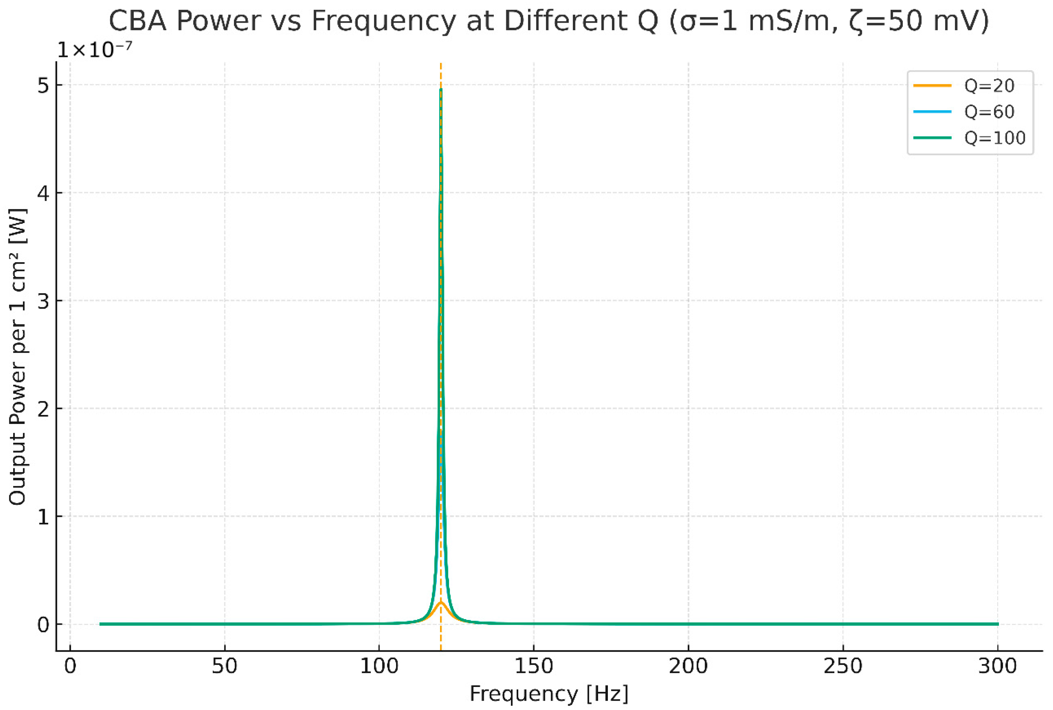
Figure 2 plots the generated power as a function of frequency (10–300 Hz) for three acoustic quality factors: Q = 20 , 60 ,   and   100 , at a fixed conductivity of 1 mS m−1 and ζ-potential of 50 mV.
Figure 2. Power vs. frequency (σ = 1 mS m−1, ζ = 50 mV) for Q = 20, 60, 100. Higher Q magnifies resonant power and narrows bandwidth, validating the acoustic-amplification term in Equation (37).
Energies 19 01150 g002
The curves exhibit the expected Lorentzian resonance behavior, peaking sharply around the Helmholtz frequency f H = 120   Hz , in direct agreement with Equation (37). Increasing the quality factor enhances the resonant amplification of the internal pressure difference Δ p , leading to a significant increase in electrical power—nearly an order of magnitude between Q = 20 and 100. This behavior confirms that the resonator effectively concentrates acoustic energy and that the amplified pressure differential is linearly transduced into a higher streaming voltage, validating the coupled expression V oc ( f ) = ζ ε η σ Δ p ( f ) .
The bandwidth reduction at higher Q also matches theoretical expectations: a narrower but taller resonance, which is beneficial when the system is tuned to a specific frequency source such as urban or vehicular acoustic noise bands. These results demonstrate that acoustic resonance can be used as a controllable gain stage in electrokinetic harvesting, confirming the theoretical model’s predictive accuracy.

4.2.2. Conductivity Dependence and Internal Optimization

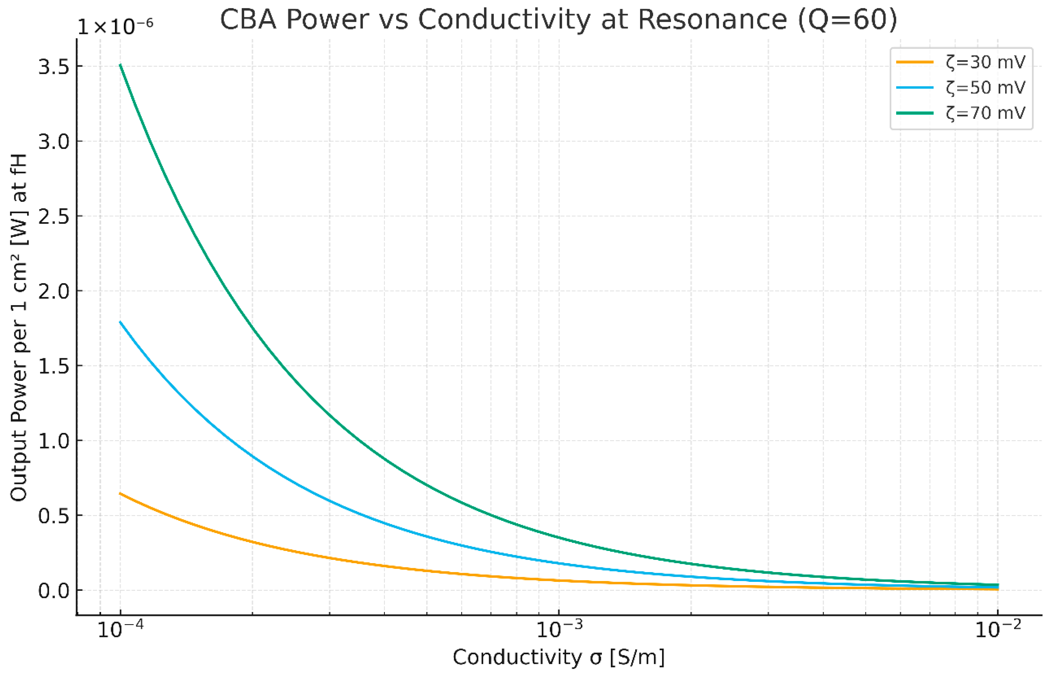
Figure 3 shows the relation between output power and electrical conductivity σ at resonance (f = f_H, Q = 60), for three ζ-potentials (30, 50, 70 mV). Each curve exhibits a clear internal maximum, indicating that the harvester’s performance is not monotonic with ionic concentration. For low σ, the internal resistance R int ∝ 1 / σ dominates, suppressing power despite large V oc . For high σ, the coupling coefficient K ∝ 1 / σ weakens, reducing voltage. Between these regimes lies an optimal conductivity range around 5 × 10⁻⁴–2 × 10⁻³ S m−1, corresponding to weakly conductive electrolytes such as deionized water with trace ionic content—conditions feasible for porous ceramic or polymer membranes.
Figure 3. Power vs. conductivity (Q = 60) for ζ = 30, 50, 70 mV. Each curve shows a distinct optimum σ ≈ 10−3 S m−1, confirming the balance between V oc gain and internal-resistance loss predicted by Equation (36).
Energies 19 01150 g003
The increase in ζ-potential shifts the entire curve upward without altering its shape, confirming that surface charge amplification improves the energy conversion linearly but does not change the fundamental balance between K   and R int . This quantitative optimization supports our earlier theoretical argument that both electrochemical and geometrical parameters must be tuned jointly to maximize energy yield.

4.2.3. Acoustic Quality Factor and Coupled Loss Mechanisms

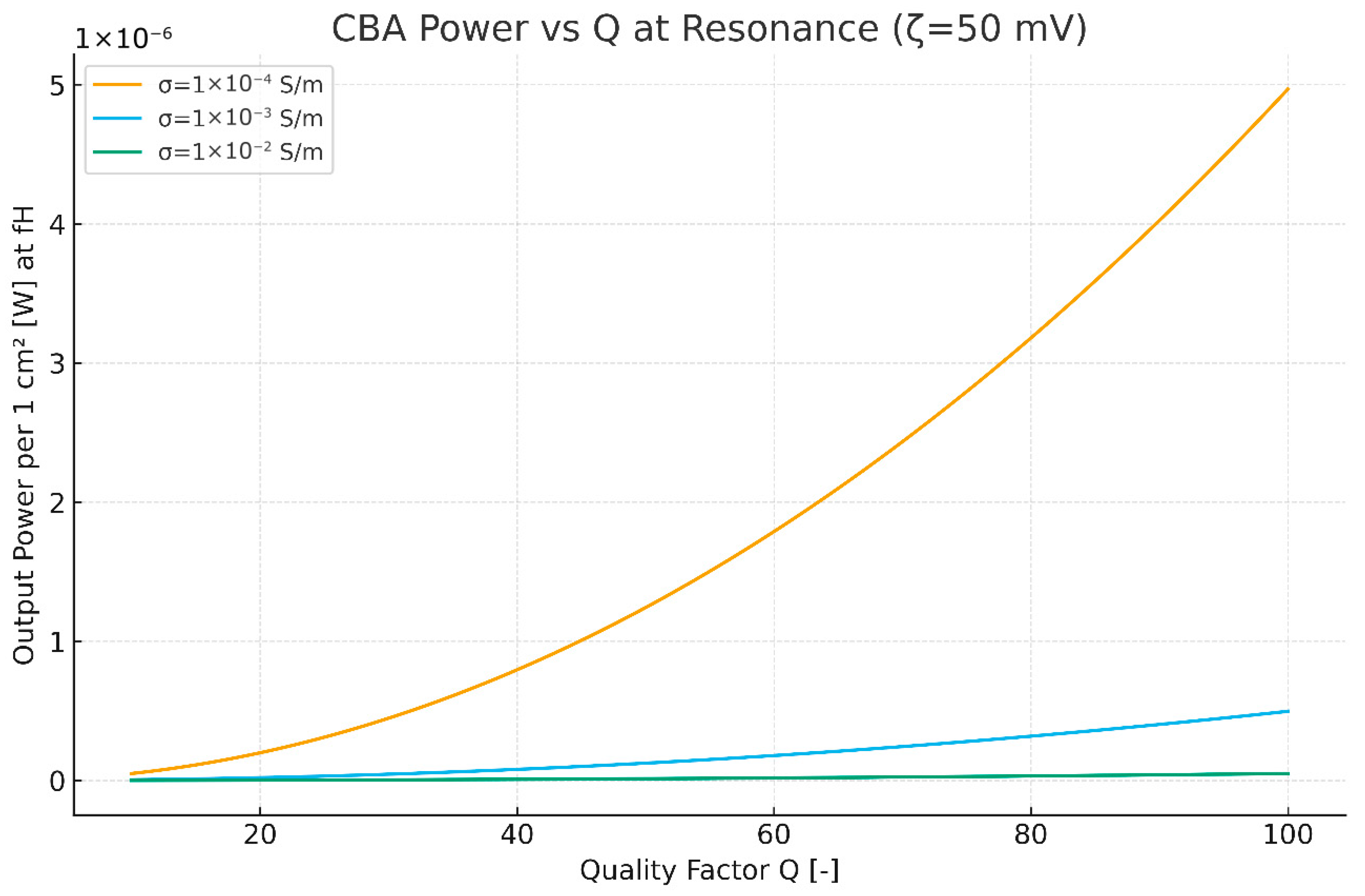
Figure 4 explores the output power at resonance as a function of the acoustic quality factor Q for three conductivities (σ = 10−4, 10−3, 10−2 S m−1) at ζ = 50 mV.
Figure 4. Power vs. Q for σ = 10−4, 10−3, 10−2 S m−1 (ζ = 50 mV). Only intermediate σ maintains an efficient balance between acoustic and electrokinetic damping.
Energies 19 01150 g004
The results illustrate how acoustic and electrokinetic losses compete. At very low σ (10−4 S m−1), ionic conduction is weak and high internal resistance limits usable power despite large V oc . At very high σ (10−2 S m−1), viscous and charge-screening effects suppress the zeta coupling, also reducing output. Only the intermediate conductivity (≈10−3 S m−1) maintains a balance, enabling monotonic improvement with Q and reaching peak efficiencies around Q = 60–100.
This behavior provides strong numerical validation for the theoretical scaling P m a x ∝ Q 2 K 2 A e q / ( L σ ) , as derived from Equations (28), (29), and (33)–(35). The interplay between acoustic confinement (controlled by Q) and electrochemical transport (controlled by σ) defines the optimal baroionic impedance match, exactly as postulated in the conceptual transducer model.

4.2.4. Multivariate Design Surfaces and Operating Windows

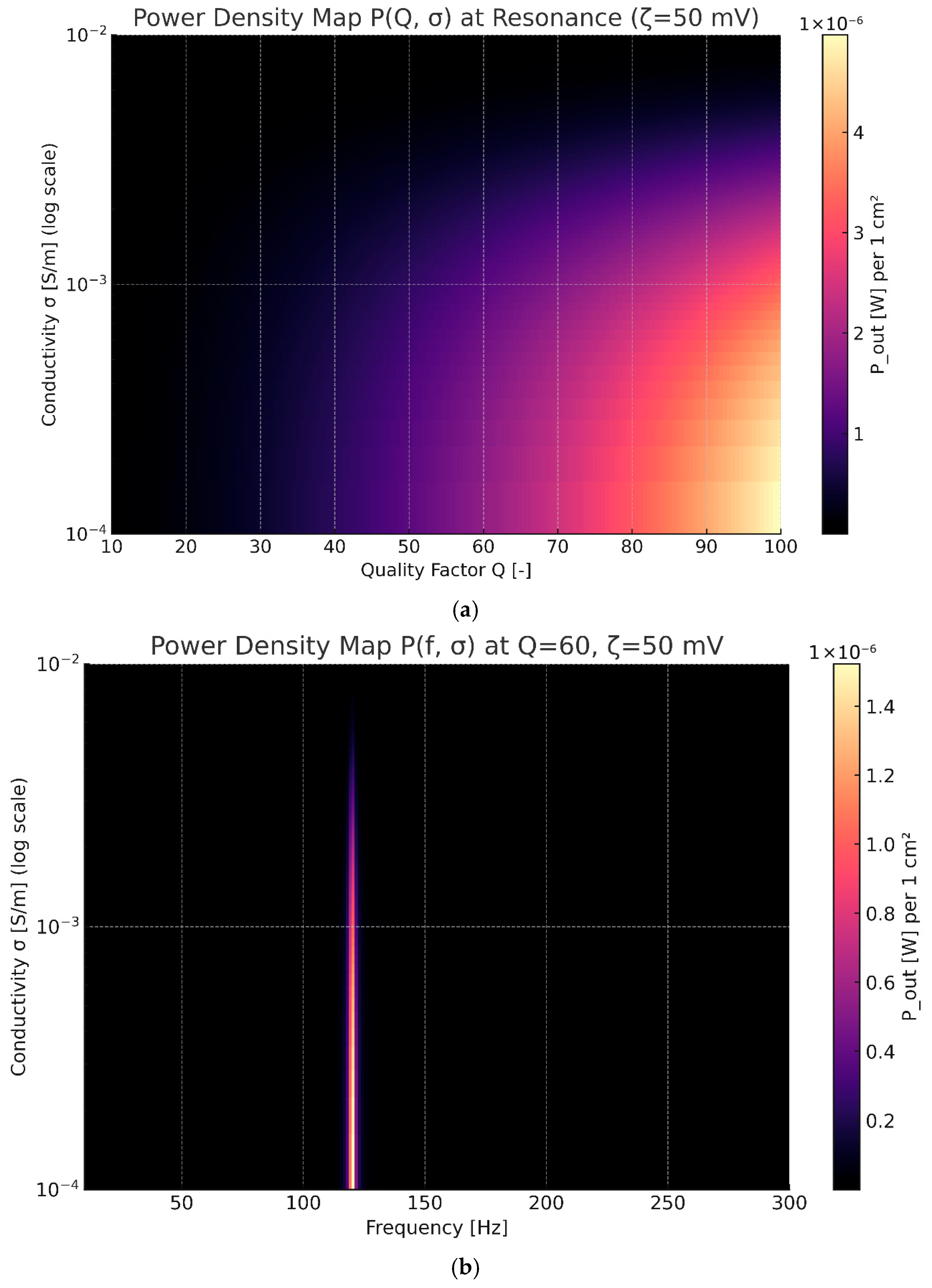
To visualize how acoustic and electrokinetic parameters interact globally, Figure 5a,b presents two-dimensional maps of output power per unit area, P ( Q , σ ) and P ( f , σ ) , using a yellow-free “magma” color scale (darker = low, bright = high). In Figure 5a, the P ( Q , σ ) map reveals a ridge of maxima extending diagonally across the plane: as Q increases, the optimum σ shifts slightly lower, maintaining an almost constant high-power contour. This confirms that devices with higher Q can operate effectively at lower electrolyte conductivities—a valuable design guideline for minimizing ionic losses in practical membranes. Figure 5b, the P ( f , σ ) surface at fixed Q = 60, shows power concentration near the resonant frequency f H ≈ 120 Hz and around σ ≈ 10−3 S m−1, matching the optima predicted independently from the 1-D sweeps. The surrounding low-power regions demonstrate the selectivity of the coupled resonator–membrane system, reaffirming that resonant acoustic forcing enhances electrokinetic transduction by over an order of magnitude within this narrow window.
Figure 5. (a). Power map P ( Q , σ ) at f = f_H (ζ = 50 mV), showing a ridge of optimal designs connecting high-Q and moderate-σ regimes. (b). Power map P ( f , σ ) at Q = 60 (ζ = 50 mV), indicating strong frequency selectivity and electrochemical tuning around f_H.
Energies 19 01150 g005
Together, these surfaces validate the predictive coherence of the ABH model, confirming that both mechanical resonance and electrochemical impedance can be tuned to maximize baroionic conversion efficiency.

4.2.5. Second-Level Numerical Validation of Model Assumptions

To strengthen the validation beyond parametric sweeps of closed-form relations, we conducted two independent “second-level” cross-checks using reduced-order numerical models that relax key idealizations used in the analytical framework.
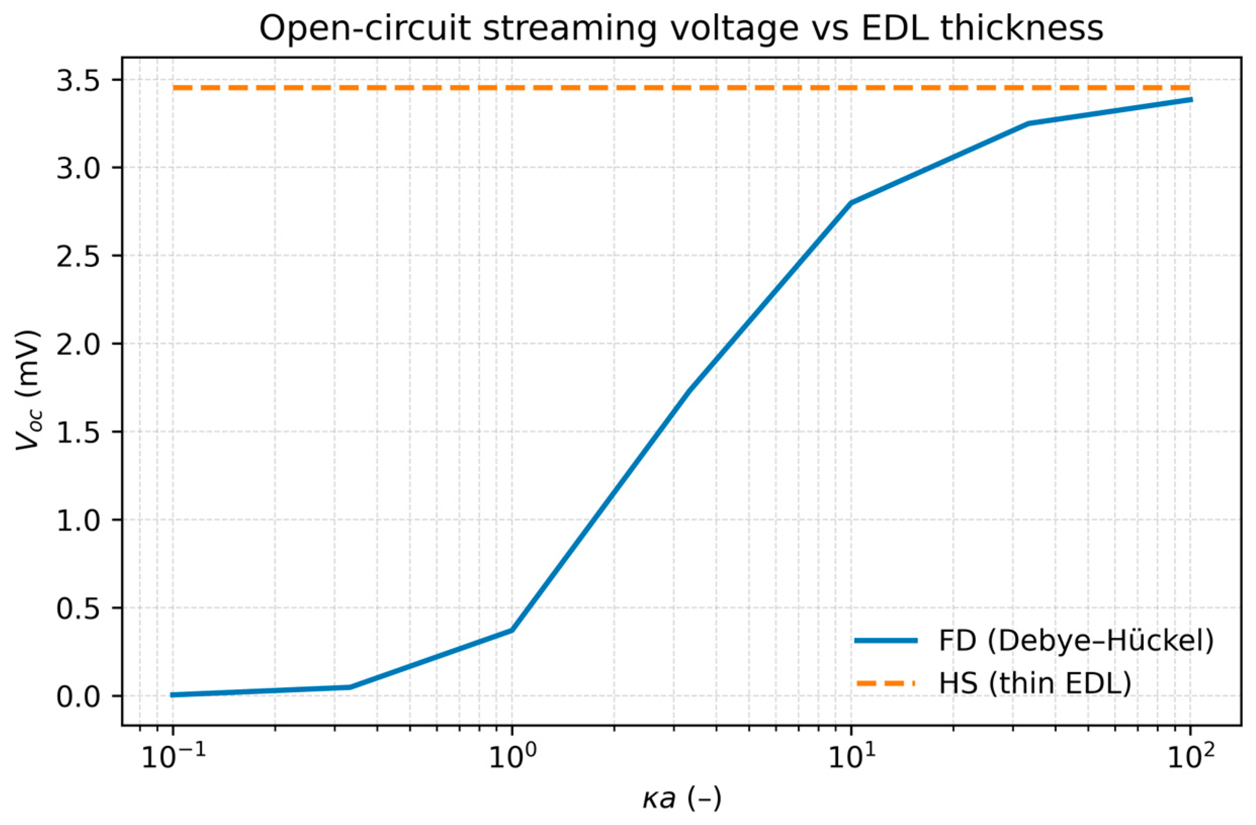
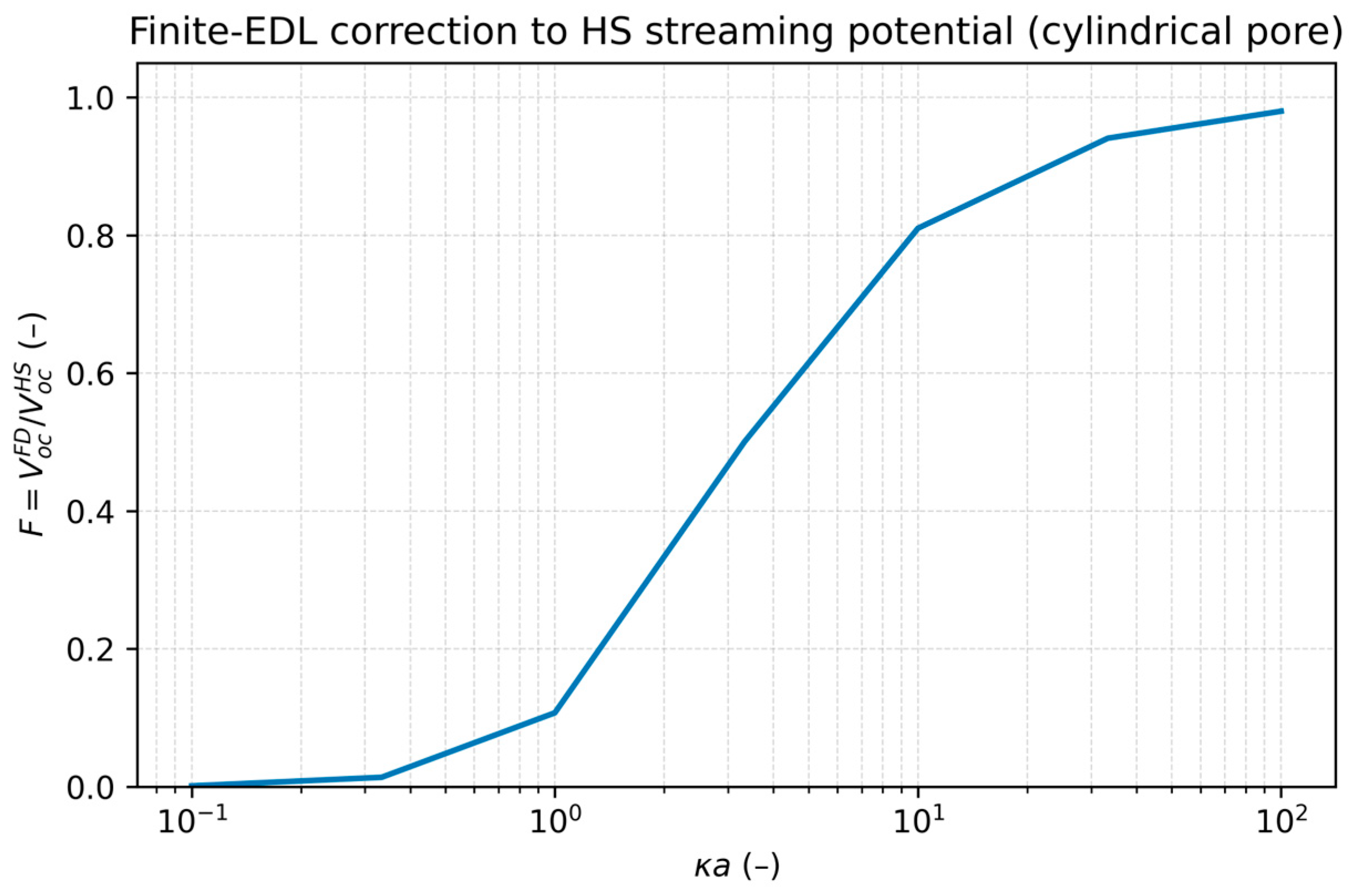
First, we examined finite-EDL electrokinetic validation. The core electrokinetic coupling in Equation (4) relies on the thin-EDL approximation ( κ a ≫ 1 ). To quantify the expected deviation at finite κ a , we solved the linearized Poisson–Boltzmann (Debye–Hückel) problem in a cylindrical pore and coupled it to pressure-driven Poiseuille flow to compute the open-circuit streaming voltage V o c F D under the same operating conditions (Figure 6). The resulting finite-EDL correction factor, F ( κ a ) = V o c F D V o c H S , is shown in Figure 7. As expected, F   increases monotonically with κ a : for thick EDL ( κ a ≪ 1 ), the streaming response collapses toward zero due to strong ionic screening, whereas, for thin EDL ( κ a ≫ 1 ), the numerical prediction converges to the Helmholtz–Smoluchowski limit. In the present validation sweep, the deviation from the thin-EDL limit decreases rapidly with κ a (e.g., ∼ 19 % at κ a ≈ 10 , ∼ 6 % at κ a ≈ 33 , and ∼ 2 % at κ a ≈ 100 ), confirming that Equation (4) is accurate in the regime relevant to the device design while also delimiting where finite-EDL effects would become non-negligible [53,54,55].
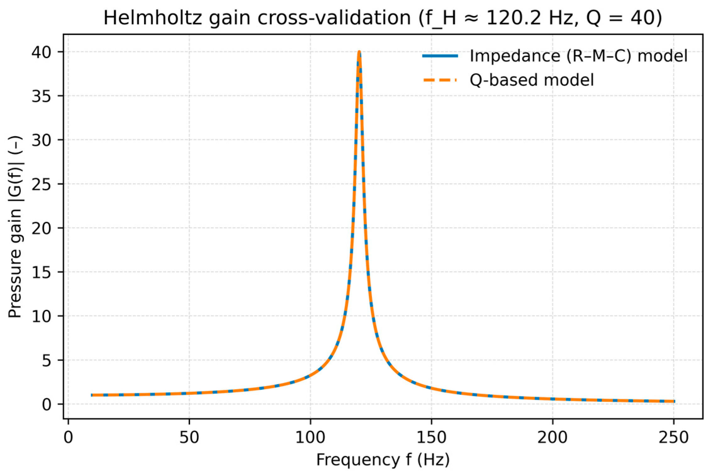
Seconds, we examined Helmholtz gain cross-validation at the operating band ( ∼ 120 Hz). The acoustic amplification used throughout the frequency-domain simulations (Equations (7)–(10)) and the gain implementation was cross-validated by comparing (i) a lumped-element acoustic impedance representation of the Helmholtz resonator (neck inertance, cavity compliance, and an effective loss resistance) against (ii) the Q-based Lorentzian gain model employed in the main sweeps. After enforcing the same resonance frequency and quality factor ( f H ≈ 120 Hz and Q = 40 ), both gain curves collapse over the full frequency sweep (Figure 8), being indistinguishable within plotting resolution.

4.3. Proposed CAD Design (Conceptual Model)

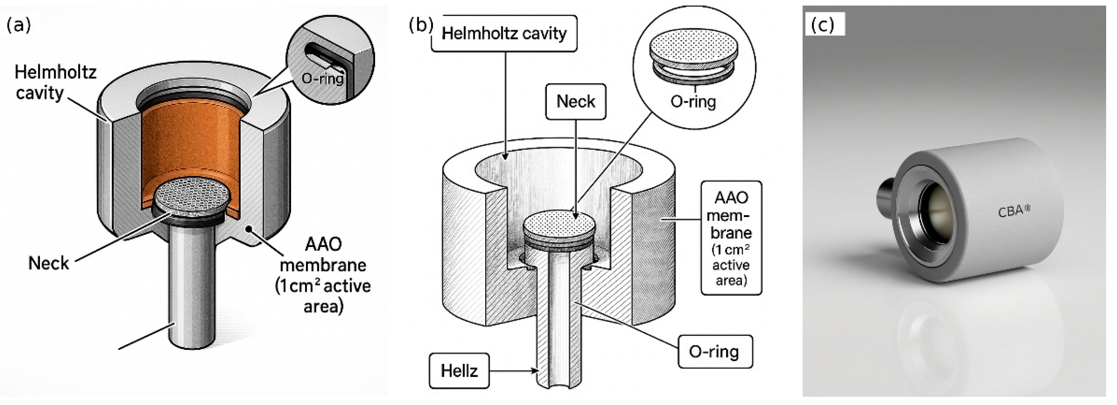
Figure 9a–c presents a conceptual CAD embodiment of the Acoustic Baroionic Energy Harvester (ABH) that is consistent with the mathematical and numerical framework developed. The design is intentionally minimal—three primary pieces plus sealing elements—so that the acoustic Helmholtz response and the electrokinetic membrane can be related as directly as possible to the analytical parameters V , A , L e q , A e q , and L . Although specific dimensions are proposed below, the geometry must be regarded as a reference implementation rather than a finalized industrial product.
In the exploded view of Figure 9a, the device is decomposed into (1) a cylindrical cavity body, (2) a membrane holder ring that hosts the AAO disk, and (3) a top cap integrating the acoustic neck. The cavity body is a cylinder of nominal diameter ϕ ≈ 50   and height of 40 mm, yielding a volume of 78 c m 3 , in agreement with the Helmholtz tuning condition
f H ≈ c 2 π A V L e q ,
where the neck cross-section A corresponds to an internal diameter of 4 mm and the effective length is L e q = L + 1.7 r   with a physical neck length of 30 mm. These values place the acoustic resonance around of 1 20   Hz and, for realistic wall losses, lead to a target quality factor Q ≈ 40 , as assumed in the simulations. The cylindrical symmetry simplifies manufacturing (machining or additive manufacturing) while providing a well-defined modal structure dominated by the fundamental Helmholtz mode.
The sectional drawing in Figure 9b details how the AAO membrane is integrated into the acoustic path. The AAO disk is clamped in a recess at the base of the cavity wall, directly at the region of maximum pressure gradient between cavity and neck. An elastomeric O-ring seals the periphery of the membrane, forcing the air–electrolyte pressure drops Δ p to appear entirely across the nanoporous region rather than through leaks or bypass gaps. This geometry is chosen so that the mechanical variable in the Helmholtz model (pressure oscillation in the cavity–neck system) maps as cleanly as possible onto the electrokinetic variable in the streaming-potential model (pressure gradient along pores of length L ), preserving the one-dimensional assumptions used in the derivation of Equations (31), (32), and (36)–(38).
The fully assembled render in Figure 9c illustrates a compact package in which the cavity body and top cap form a monolithic shell (for instance, in PA12 or anodized aluminum), while the membrane holder ring and O-ring are hidden within the front interface. In this configuration, the external acoustic field couples through the neck into the Helmholtz cavity; the resonantly amplified pressure oscillation develops across the AAO membrane, driving the baroionic streaming current and generating the open-circuit voltage V o c = ( ζ ε / η σ ) Δ p . The electrical terminals would be connected across the two faces of the AAO disk, realizing physically the Thevenin source { V s = K Δ p ,   R i n t = L / ( σ A e q ) } .
Technically, this geometry is proposed because it simultaneously (i) satisfies the Helmholtz resonance condition at 120 Hz with Q ≈ 40   using realistic, compact dimensions; (ii) implements a well-defined, one-dimensional pressure drop across a porous membrane of area and thickness identical to those used in the simulations; and (iii) provides clear mechanical degrees of freedom for tuning: the cavity height or diameter can be adjusted to retune f H , while the neck diameter and surface roughness can be used to control Q and the effective acoustic coupling. Alternative shapes (e.g., slightly elongated cavities or angled necks) that preserve the same V , A , and L e q would be acoustically equivalent, but the present cylindrical layout offers a straightforward path from the mathematical design space to an experimentally buildable prototype.

4.4. Application Scenarios

The ABH concept is intended for environments where low-frequency acoustic pressure is abundant but largely wasted: ventilation ducts, façade elements exposed to traffic noise, and industrial structures with strong infrasound/low-frequency vibration. These environments typically exhibit dominant components between about 10 and 250 Hz, precisely the band for which the ABH can be tuned via the Helmholtz parameters ( V , A , L e q ) . Low-power acoustic energy harvesters have already demonstrated that μW–mW levels are sufficient to drive wireless sensor nodes when energy is buffered in capacitors or supercapacitors.

4.4.1. Ventilation Ducts (HVAC)

Noise from HVAC fans, variable-air-volume (VAV) valves, and rooftop units is known to have strong low-frequency content. The ASHRAE sound and vibration handbook shows that fan noise mainly occupies the 16–250 Hz octave bands, with the 63 Hz band being particularly important for comfort criteria in occupied spaces. A recent review of HVAC noise reports that large rooftop units can generate significant low-frequency components from 8 to 250 Hz, often requiring specific mitigation measures. Practical guides on duct silencers emphasize that primary sound traps should attenuate frequencies below about 500 Hz, because these bands concentrate most of the acoustic energy.
In this context, the ABH can be integrated as a side-branch Helmholtz resonator inside supply or return ducts, tuned to the dominant low-frequency tone without significantly disturbing airflow. The incident duct sound with A-weighted levels typically between 60 and 80 dB in occupied spaces corresponds to higher local levels inside ducts close to the fan; in our model, this translates into external pressure amplitudes p e n v   in the range used, which are further amplified by the factor Q   at resonance. Because the ABH behaves acoustically as a dissipative side branch with high acoustic impedance at resonance, it can play a dual role: partial noise control (similar to a micro-silencer) and baroionic energy harvester. Arrays of ABHs distributed along a duct run could provide a few microwatts per unit, which is compatible with the power demands of duty-cycled temperature, humidity, or vibration nodes that transmit intermittently via low-power RF links.

4.4.2. Window Frames and Urban Traffic Noise

Urban road traffic typically generates broadband noise with overall levels between about 50 and 96 dB(A), depending on traffic composition and measurement location. Studies on elevated urban roads show that horn honking produces peaks of 80.2–98.6 dB(A), and heavy-vehicle braking introduces additional low-frequency components. Frequency-spectrum analyses of road traffic noise reveal substantial energy in bands from 63 to 250 Hz associated with engine, tire/road, and bridge resonance effects.
These characteristics match well the tunable band of the ABH. A compact version of the device, mechanically embedded in window frames or façade vents, could be tuned to local traffic resonances around 80–160 Hz. For A-weighted exterior levels of 70–90 dB(A) at the façade, the incident acoustic intensity is comparable to the levels used in recent high-performance acoustic harvesters (e.g., nanomesh or magnetoelastic membranes operating around 90–100 dB SPL). Under these conditions, the ABH’s predicted open-circuit voltages (tens of millivolts) and power densities are sufficient for ultra-low-power sensor nodes that only need to sample a few variables (noise level, temperature, window state) and communicate sporadically to a local gateway. Because the ABH is passive and solid-state on the acoustic side, it can be embedded without affecting the structural integrity of frames and could be factory-tuned for different designs and local traffic spectra.

4.4.3. Industrial Infrastructure and Infrasonic Vibrations

Industrial facilities such as flare stacks, large compressors, pipelines, and wind-energy installations can generate pronounced low-frequency noise and infrasound. Broad reviews on environmental low-frequency noise highlight a relevant band from 10 to 200 Hz that includes both audible low-frequency sound and infrasound just below 20 Hz. A NIOSH investigation of methane flares, for example, reported that the operation of a flare increased one-third-octave levels in the 16–25 Hz bands by 12–17 dB over background inside nearby buildings, indicating considerable low-frequency energy transmitted through structures.
While the present ABH prototype is tuned around 120 Hz, the same design principles allow re-tuning to industrial low-frequency bands (e.g., 30–80 Hz) by increasing the cavity volume or neck length. In piping systems or structural elements, ABH units could be attached as Helmholtz side branches filled with electrolyte and AAO membranes, converting pressure oscillations and structural-borne acoustic modes into electrical power. Such ABHs would be particularly suited for powering permanently installed monitoring nodes (corrosion, leak detection, strain, or acoustic-emission sensors) where battery replacement is difficult or hazardous. The streaming-potential mechanism is, in principle, insensitive to electromagnetic interference and can therefore coexist with high-EMI machinery environments.

4.4.4. Integration with IoT and Wireless Sensor Networks

The feasibility of using harvested acoustic energy to power wireless sensing has been demonstrated in several experimental systems. Self-powered wireless sensors have been built using pressure-fluctuation harvesters with acoustic resonators and piezoelectric stacks to supply both sensing and radio transmission. Other works have designed acoustic harvesters specifically for low-power wireless sensor networks, emphasizing that μW-level average powers are sufficient when energy is buffered and nodes are duty-cycled. Recent membrane-type acoustic generators have shown the ability to charge a 47 μF capacitor to 2 V in 20 s at 95 dB SPL, corresponding to tens to hundreds of microwatts, depending on the effective area.
Within this landscape, the ABH can be viewed as a complementary transducer optimized for low-frequency, pressure-driven environments where traditional piezoelectric harvesters are less efficient. For a given deployment, ABH units would be connected to a power-management circuit (rectifier, DC–DC converter, and storage capacitor). The IoT node (microcontroller, sensor front-end, and radio, e.g., BLE or LoRa) would wake up only when the stored energy exceeds a threshold—thereby matching its average power consumption (typically a few μW to tens of μW) to the average harvested power predicted by the ABH model. Central gateways could aggregate data from multiple ABHs, effectively transforming existing noisy infrastructures (ventilation ducts, façades, industrial plants) into distributed, self-powered sensing networks (Table 2).
These scenarios indicate that the pressure and frequency conditions assumed in our mathematical and numerical model are consistent with real acoustic environments, supporting the practical feasibility of the proposed ABH concept for self-powered IoT sensing.

5. Discussion

The results presented in this study establish a coherent framework for acoustic–electrokinetic energy harvesting and demonstrate that coupling a Helmholtz resonator with a nanoporous AAO membrane can yield measurable electrical power from low-frequency pressure oscillations. The proposed Acoustic Baroionic Harvester (ABH) operates by transforming amplified acoustic pressure into streaming-potential-driven ionic currents, thereby eliminating mechanical moving parts common in piezoelectric, triboelectric, or electromagnetic harvesters. The analytical expressions derived show that the open-circuit voltage scales linearly with the resonator-induced pressure differential and with the electrokinetic coupling factor K = ζ ε / ( η σ ) , while the output power grows quadratically with Δ p . This behavior was fully reproduced by the numerical simulations, which identified an optimal parametric window where 40–100 mV/cm2 and 0.1–1 μW/cm2 can be produced using realistic values of ζ , σ , and Q . These magnitudes are consistent with experimental measurements from pressure-driven electrokinetic generators employing nanoporous glass or AAO membranes under moderate hydrodynamic forcing [31,35], reinforcing the physical plausibility of the mechanism.
A central implication of these findings is that acoustic resonance provides a passive and frequency-selective “pressure pump” capable of driving electrokinetic conversion without mechanical contact. This is particularly relevant because many low-frequency ambient acoustic fields—such as HVAC ducts—exhibit spectral peaks in the 20–250 Hz range, precisely where Helmholtz resonators can be compactly tuned. Conventional vibration harvesters often struggle in this frequency band due to the large mechanical amplitude required for piezoelectric or electromagnetic devices, while triboelectric generators experience rapid degradation in humid or dusty environments. The solid-state nature of the ABH therefore addresses a major durability limitation observed in triboelectric systems, which frequently suffer charge losses and mechanical wear under moisture exposure [11,36,38,39,40].
To explicitly position the proposed acoustically boosted electrokinetic harvester (ABH) within the broader landscape of low-power energy harvesting, Table 3 summarizes representative ambient sources, conversion mechanisms, operating regimes, typical power orders, and key trade-offs.
Comparative evaluation further highlights the distinct niche occupied by the ABH. Piezoelectric harvesters, although exhibiting high power density under resonance, remain constrained by bandwidth and material fatigue—issues evident in magnetic-plucking and inertial-upconversion systems, which broaden frequency response at the cost of mechanical complexity [3,60]. Electromagnetic harvesters excel in moderate-to-high amplitudes but require moving parts and cannot efficiently operate at low acoustic pressure levels commonly found in ventilation or façade environments [14]. Thermoelectric harvesters provide excellent stability yet depend on temperature gradients rarely present in indoor or quasi-isothermal environments [17]. Meanwhile, triboelectric nanogenerators, while highly versatile, are limited by surface-charge instability in humid flow channels and by contact degradation—factors incompatible with long-term operation inside air ducts or external architectural components [13]
By contrast, the ABH leverages ion transport rather than solid-state deformation, enabling robust operation in humid or dusty environments where mechanical wear is problematic. Since electrokinetic devices rely on fluid–wall interactions rather than interface contact, they are inherently compatible with airflow-based systems and do not require lubrication, bearings, or mechanical supports. Furthermore, the ABH’s output, although modest compared to piezoelectric harvesters under strong vibrations, aligns well with the requirements of emerging ultra-low-power IoT architectures, which can operate on duty-cycled microwatt budgets [18]. The ability to extract consistent energy from sustained acoustic fields—rather than sporadic large-amplitude events—creates a pathway toward permanent, maintenance-free power sources for environmental sensing, indoor air-quality monitoring, structural-health diagnostics, and distributed edge computing.
The main limitations of the present study concern the small signal regime, the assumption of laminar flow, and the use of linear acoustics. Future work should examine nonlinear effects at higher sound pressure levels, the influence of electrolyte composition, and long-term membrane stability under continuous oscillation. Nonetheless, given the strong agreement between mathematical predictions, numerical simulations, and physical feasibility demonstrated in analogous electrokinetic generators, the ABH emerges as a promising new class of low-frequency harvesters that exploit an energy resource abundant in-built environments but largely untapped.

6. Conclusions

This study developed an integrated analytical–computational framework for an Acoustic Baroionic Harvester (ABH) that converts low-frequency acoustic pressure into electrical output through Helmholtz-resonator amplification and streaming-potential electrokinetics. The coupled formulation establishes explicit scaling links between acoustic forcing, electrokinetic coupling, and extractable electrical power, and the frequency-domain simulations reproduce these trends while delineating a practical operating window.
Quantitatively, the results identify a clear internal optimum in electrolyte conductivity, with the highest performance concentrated around σ ≈ 5 × 10 − 4   –   2 × 10 − 3   S m − 1 under the simulated geometry and operating band.
Surface charge also acts as a first-order lever: increasing ζ within the explored 30–70 mV range shifts output upward without altering the location of the conductivity optimum.
Within the 10–300 Hz band, the ABH exhibits strong resonant selectivity: increasing the resonator quality factor increases peak output while narrowing bandwidth, supporting targeted tuning to dominant low-frequency noise components.
Under the realistic parameter sets explored, the optimal region yields open-circuit voltages up to 100 mV cm−2 and matched-load power densities up to 1 μW cm−2, with maximum power obtained under the standard matched-load condition R o p t = R i n t (external loads in the 1–10 kΩ sweep range used here).
Beyond the main sweeps, two reduced-order “second-level” validations were implemented: (i) a finite-difference Debye–Hückel pore solver to test the thin-EDL electrokinetic approximation and (ii) an independent impedance-based Helmholtz model to cross-check the Q-based gain implementation. These checks add confidence that the reported trends arise from physically consistent acoustic amplification and electrokinetic transduction rather than numerical artifacts.
Future work should prioritize experimental prototyping in duct-like environments to measure (i) achievable membrane pressure differentials in the p e n v = 0.1 – 2 × 10 3   P   range adopted in the design envelope, (ii) long-term electrochemical stability and fouling in sealed electrolyte microcavities, and (iii) bandwidth-broadening strategies (e.g., multi-resonator arrays or adaptive tuning).
Overall, the ABH is positioned as a complementary, solid-state alternative within acoustic energy harvesting, particularly where humidity and particulate exposure can degrade triboelectric or moving-contact devices.

Author Contributions

Conceptualization, J.G.; methodology, J.G.; software, J.B., I.Q.; validation, J.G.; formal analysis, J.G.; investigation, J.G., J.B., I.Q.; resources, G.C.; data curation, J.G.; writing—original draft preparation, J.G., J.B., I.Q.; writing—review and editing, J.G., G.C.; visualization, J.G.; supervision, J.G., G.C.; project administration, J.G., G.C. All authors have read and agreed to the published version of the manuscript.

Funding

This research received no external funding.

Data Availability Statement

All Python simulation scripts, intermediate datasets, and CAD source files used in this study are available from the corresponding author upon reasonable request. No publicly archived datasets were generated or analyzed in this work.

Acknowledgments

The author gratefully acknowledges technical support from the Universidad Técnica del Norte. During the preparation of this manuscript, the author used ChatGPT (OpenAI, GPT-5.1) exclusively for language polishing, clarity enhancements, grammar correction, and formatting suggestions. All scientific content, equations, theoretical developments, simulations, and conclusions were entirely generated, verified, and validated by the authors, who assumes full responsibility for the published material.

Conflicts of Interest

The authors declare no conflicts of interest.

Abbreviations

The following abbreviations are used in this manuscript:
AAOAnodic Aluminum Oxide
ABHAcoustic Baroionic Harvester
EDLElectric Double Layer
IoTInternet of Things

References

  1. Mahmud, M.A.P.; Bazaz, S.R.; Dabiri, S.; Mehrizi, A.A.; Asadnia, M.; Warkiani, M.E.; Wang, Z.L. e Advances in MEMS and Microfluidics-Based Energy Harvesting Technologies. Adv. Mater. Technol. 2022, 7, 2101347. [Google Scholar] [CrossRef] [Scilit]
  2. Ullah, Q.; Rauta, T.; Keskikuru, J.; Haverinen, J.; Ruuskanen, P. Innovations in Energy Harvesting: A Survey of Low-Power Technologies and Their Potential. Energy Rep. 2025, 14, 671–692. [Google Scholar] [CrossRef] [Scilit]
  3. Rosso, M.; Nastro, A.; Baù, M.; Ferrari, M.; Ferrari, V.; Corigliano, A.; Ardito, R. Piezoelectric Energy Harvesting from Low-Frequency Vibrations Based on Magnetic Plucking and Indirect Impacts. Sensors 2022, 22, 5911. [Google Scholar] [CrossRef] [Scilit] [PubMed]
  4. Chen, J.; Xu, J.; Guan, M.; Shen, Z.; Cheng, Z. Study of an Ultra-Low-Frequency Inertial Vibration Energy Harvester with a Frequency Up-Conversion Approach. Micromachines 2025, 16, 942. [Google Scholar] [CrossRef] [Scilit] [PubMed]
  5. Wang, S.; Wen, L.; Gong, X.; Liang, J.; Hou, X.; Hou, F. Piezoelectric-Based Energy Conversion and Storage Materials. Batteries 2023, 9, 371. [Google Scholar] [CrossRef] [Scilit]
  6. Collaguazo, G.; Guerra, J.; Guatemal, W. Electric Generation from Hydraulic Fluctuations Using Piezoelectric Ceramics. In 2022 IEEE Sixth Ecuador Technical Chapters Meeting (ETCM), Quito, Ecuador, 11–14 October 2022; IEEE: Piscataway, NJ, USA, 2022; pp. 1–5. [Google Scholar]
  7. Choi, D.; Lee, Y.; Lin, Z.-H.; Cho, S.; Kim, M.; Ao, C.K.; Soh, S.; Sohn, C.; Jeong, C.K.; Lee, J.; et al. Recent Advances in Triboelectric Nanogenerators: From Technological Progress to Commercial Applications. ACS Nano 2023, 17, 11087–11219. [Google Scholar] [CrossRef] [Scilit]
  8. Shi, Z.; Zhang, Y.; Gu, J.; Liu, B.; Fu, H.; Liang, H.; Ji, J. Triboelectric Nanogenerators: State of the Art. Sensors 2024, 24, 4298. [Google Scholar] [CrossRef] [Scilit]
  9. Xiang, H.; Peng, L.; Yang, Q.; Wang, Z.L.; Cao, X. Triboelectric Nanogenerator for High-Entropy Energy, Self-Powered Sensors, and Popular Education. Sci. Adv. 2024, 10, ads2291. [Google Scholar] [CrossRef] [Scilit]
  10. Zhang, J.; Boyer, C.; Zhang, Y.X. Enhancing the Humidity Resistance of Triboelectric Nanogenerators: A Review. Small 2024, 20, e2401846. [Google Scholar] [CrossRef] [Scilit]
  11. Nazar, A.M.; Mohsenian, R.; Rayegani, A.; Shadfar, M.; Jiao, P. Skin-Contact Triboelectric Nanogenerator for Energy Harvesting and Motion Sensing: Principles, Challenges, and Perspectives. Biosensors 2023, 13, 872. [Google Scholar] [CrossRef] [Scilit]
  12. Guerra, J.; Quinde, I.; Collaguazo, G.; Martínez, A.; León, G. Determining the Predominant Materials for Triboelectric Nanogenerator Fabrication: A Bibliometric and a Systematic Analysis. Data Metadata 2025, 4, 764. [Google Scholar] [CrossRef] [Scilit]
  13. Guerra, J.; Collaguazo, G. Development of Low-Cost Triboelectric Nanogenerators for Rural Communities in Ecuador. In Proceedings of the Applied Engineering and Innovative Technologies 2023, Ibarra, Ecuador, 22–24 November 2023; pp. 45–53. [Google Scholar]
  14. Muscat, A.; Bhattacharya, S.; Zhu, Y. Electromagnetic Vibrational Energy Harvesters: A Review. Sensors 2022, 22, 5555. [Google Scholar] [CrossRef] [Scilit]
  15. Weiwei, H.; Zengwei, L.; Zhuohao, L.; Xudong, Y.; Xiaoning, L. A Low-Frequency Rotating Electromagnetic Vibration Energy Harvester. Sustain. Energy Technol. Assess. 2025, 82, 104492. [Google Scholar] [CrossRef] [Scilit]
  16. Monsury, M.I.; Sanchez, A.; Amjadian, M.; Tarawneh, C. Frequency Up-Conversion Electromagnetic Energy Harvester for Generating Electrical Power from Vibration of Beams under Moving Load. In Active and Passive Smart Structures and Integrated Systems XIX, Proceedings of the SPIE Smart Structures + Nondestructive Evaluation, Vancouver, BC, Canada, 17–20 March 2025; Tol, S., Nouh, M.A., Yang, J., Li, X., Chen, Y., Huang, G., Sugino, C., Eds.; SPIE: Bellingham, WA, USA, 2025; p. 32. [Google Scholar]
  17. Kucova, T.; Prauzek, M.; Konecny, J.; Andriukaitis, D.; Zilys, M.; Martinek, R. Thermoelectric Energy Harvesting for Internet of Things Devices Using Machine Learning: A Review. CAAI Trans. Intell. Technol. 2023, 8, 680–700. [Google Scholar] [CrossRef] [Scilit]
  18. Dai, J.; Deng, H.; Huang, J.; Zhang, X. Recent Progress of Powering IoT Based on Thermoelectric Technology. Micromachines 2025, 16, 1017. [Google Scholar] [CrossRef] [Scilit] [PubMed]
  19. Aragonés, R.; Oliver, J.; Ferrer, C. Transforming Industrial Maintenance with Thermoelectric Energy Harvesting and NB-IoT: A Case Study in Oil Refinery Applications. Sensors 2025, 25, 703. [Google Scholar] [CrossRef] [Scilit]
  20. Botero-Valencia, J.; Sanin-Villa, D.; Valencia-Aguirre, J. A Simple Method for Harvesting Thermoelectric Energy in Home and Industrial Appliances Heat Cycle Using Peltier Cells. EUREKA Phys. Eng. 2023, 5, 46–55. [Google Scholar] [CrossRef] [Scilit]
  21. Ding, Z.; Chang, L.; Tian, K.; Jian, Y. On the Energy Conversion in Electrokinetic Transports. Appl. Math. Mech. 2022, 43, 263–274. [Google Scholar] [CrossRef] [Scilit]
  22. Gao, X.; Zhao, G.; Zhang, Y.; Zhang, Y. Electrokinetic Energy Conversion of Nanofluids in Porous Microtubes with Green’s Function. Open Phys. 2023, 21, 20230173. [Google Scholar] [CrossRef] [Scilit]
  23. Yaroshchuk, A.; Zholkovskiy, E. Streaming Potential with Ideally Polarizable Electron-Conducting Substrates. Langmuir 2022, 38, 9974–9980. [Google Scholar] [CrossRef] [Scilit]
  24. Fang, S.; Lu, H.; Chu, W.; Guo, W. Mechanism of Water-Evaporation-Induced Electricity beyond Streaming Potential. Nano Res. Energy 2024, 3, e9120108. [Google Scholar] [CrossRef] [Scilit]
  25. Kaur, M.; Ishii, S.; Nozaki, R.; Nagao, T. Hydropower Generation by Transpiration from Microporous Alumina. Sci. Rep. 2021, 11, 10954. [Google Scholar] [CrossRef] [Scilit] [PubMed]
  26. Xie, Z.; Jian, Y.; Tan, W. Streaming Potential Analysis and Electrokinetic Energy Conversion Efficiency of Two Immiscible Fluids in a Nanochannel. Sens. Actuators B Chem. 2018, 273, 1257–1268. [Google Scholar] [CrossRef] [Scilit]
  27. van der Heyden, F.H.J.; Bonthuis, D.J.; Stein, D.; Meyer, C.; Dekker, C. Electrokinetic Energy Conversion Efficiency in Nanofluidic Channels. Nano Lett. 2006, 6, 2232–2237. [Google Scholar] [CrossRef] [Scilit] [PubMed]
  28. Liu, G.; Chen, T.; Xu, J.; Wang, K. Blue Energy Harvesting on Nanostructured Carbon Materials. J. Mater. Chem. A 2018, 6, 18357–18377. [Google Scholar] [CrossRef] [Scilit]
  29. Ding, Z.; Tian, K.; Jian, Y. Electrokinetic Flow and Energy Conversion in a Curved Microtube. Appl. Math. Mech. 2022, 43, 1289–1306. [Google Scholar] [CrossRef] [Scilit]
  30. Jian, Y. Electrokinetic Energy Conversion of Fluids with Pressure-Dependent Viscosity in Nanofluidic Channels. Int. J. Eng. Sci. 2022, 170, 103590. [Google Scholar] [CrossRef] [Scilit]
  31. Tanaka, Y.; Amaya, S.; Funano, S.-I.; Sugawa, H.; Nagafuchi, W.; Ito, Y.; Aishan, Y.; Liu, X.; Kamamichi, N.; Yalikun, Y. A Pressure Driven Electric Energy Generator Exploiting a Micro- to Nano-Scale Glass Porous Filter with Ion Flow Originating from Water. Sci. Rep. 2022, 12, 16827. [Google Scholar] [CrossRef] [Scilit]
  32. Zhang, Y.; Zhao, G.; Hou, Y.; Zhang, J.; Xue, B. The Electrokinetic Energy Conversion Analysis of Viscoelastic Maxwell Nanofluids with Couple Stress in Circular Microchannels. Phys. Fluids 2024, 36, 093106. [Google Scholar] [CrossRef] [Scilit]
  33. Gillespie, D. High Energy Conversion Efficiency in Nanofluidic Channels. Nano Lett. 2012, 12, 1410–1416. [Google Scholar] [CrossRef] [Scilit]
  34. Wang, J.; Song, Z.; He, M.; Qian, Y.; Wang, D.; Cui, Z.; Feng, Y.; Li, S.; Huang, B.; Kong, X.; et al. Light-Responsive and Ultrapermeable Two-Dimensional Metal-Organic Framework Membrane for Efficient Ionic Energy Harvesting. Nat. Commun. 2024, 15, 2125. [Google Scholar] [CrossRef] [Scilit] [PubMed]
  35. Fan, P.; Wang, D.; Zhang, Y.; Jiang, R.; Gu, H. An Efficient Traffic Acoustic Energy Harvester Using Optimized Helmholtz Resonators for Sustainable Roadside Power Generation and Smart Monitoring. Energy Convers. Manag. X 2025, 28, 101289. [Google Scholar] [CrossRef] [Scilit]
  36. Zhou, S.; Jia, C.; Shu, G.; Guan, Z.; Wu, H.; Li, J.; Ou-Yang, W. Recent Advances in TENGs Collecting Acoustic Energy: From Low-Frequency Sound to Ultrasound. Nano Energy 2024, 129, 109951. [Google Scholar] [CrossRef] [Scilit]
  37. Zhang, Q.; Xi, Z.; Wang, Y.; Liu, L.; Yu, H.; Wang, H.; Xu, M. Multi-Tube Helmholtz Resonator Based Triboelectric Nanogenerator for Broadband Acoustic Energy Harvesting. Front. Mater. 2022, 9, e896953. [Google Scholar] [CrossRef] [Scilit]
  38. Jean, F.; Khan, M.U.; Alazzam, A.; Mohammad, B. Advancement in Piezoelectric Nanogenerators for Acoustic Energy Harvesting. Microsyst. Nanoeng. 2024, 10, 197. [Google Scholar] [CrossRef] [Scilit]
  39. Wang, X.; Zhang, S.; Shen, G. Research on Acoustic Energy Power Generation System Based on Dual Cavity Structure Helmholtz Resonator and Modified Piezoelectric Ceramics. ACS Omega 2025, 10, 19335–19349. [Google Scholar] [CrossRef] [Scilit]
  40. Che, Z.; Xu, J.; Wan, X.; Duan, C.; Chen, J. A Membrane Magnetoelastic Generator for Acoustic Energy Harvesting. Adv. Sci. 2025, 12, e2409063. [Google Scholar] [CrossRef] [Scilit] [PubMed]
  41. Delgado, A.; González-Caballero, F.; Hunter, R.; Koopal, L.; Lyklema, J. Measurement and Interpretation of Electrokinetic Phenomena. J. Colloid Interface Sci. 2007, 309, 194–224. [Google Scholar] [CrossRef] [Scilit]
  42. Zhang, X.; Zhao, M.; Wang, K. Experimental Study on the Streaming Potential Phenomenon Response to Compactness and Salinity in Soil–Rock Mixture. Water 2021, 13, 2071. [Google Scholar] [CrossRef] [Scilit]
  43. Chang, Q. Electrical Properties. In Colloid and Interface Chemistry for Water Quality Control; Elsevier: Amsterdam, The Netherlands, 2016; pp. 79–136. [Google Scholar]
  44. Dogra, S.; Gupta, A. Design, Manufacturing, and Acoustical Analysis of a Helmholtz Resonator-Based Metamaterial Plate. Acoustics 2021, 3, 630–641. [Google Scholar] [CrossRef] [Scilit]
  45. Indenbom, M.V.; Pogossian, S.P. Characteristics of Partially Filled Helmholtz Resonators. Acta Acust. 2023, 7, 51. [Google Scholar] [CrossRef] [Scilit]
  46. Omoteso, K.A.; Ozioko, O.; Bagdasar, O.; Roy-Layinde, T.O.; Diala, U.H. Numerical Analyses of Acoustic Vibrational Resonance in a Helmholtz Resonator. Nonlinear Dyn. 2025, 113, 23955–23975. [Google Scholar] [CrossRef] [Scilit]
  47. Omoteso, K.; Marjani, R.; Ozioko, O.; Bagdasar, O.; Roy-Layinde, T.; Diala, U. A Study of the Response Dynamics of a Helmholtz Resonator and Its Application in Acoustic Energy Harvesting. Results Eng. 2025, 27, 106470. [Google Scholar] [CrossRef] [Scilit]
  48. Aguilar-Torres, D.; Jimenez-Ramirez, O.; Flores-Acoltzi, O.; Jimenez-Garcia, J.A.; Luque-Zuniga, G.; Vazquez-Medina, R. Environmental Noise Harvester Using a Helmholtz Resonator and Piezoelectric Transducer. Int. J. Acoust. Vib. 2022, 27, 301–314. [Google Scholar] [CrossRef] [Scilit]
  49. Li, Z.; Zou, H.; Li, J.; Chen, H. Research Progress of Cavity-Based Acoustic Energy Harvester. J. Vibroeng. 2021, 23, 1680–1693. [Google Scholar] [CrossRef] [Scilit]
  50. Huang, Y.; Du, T.; Xiang, C.; Zhang, Y.; Si, J.; Yu, H.; Yuan, H.; Sun, P.; Xu, M. Research Progress of Acoustic Energy Harvesters Based on Nanogenerators. Int. J. Energy Res. 2023, 2023, 5568046. [Google Scholar] [CrossRef] [Scilit]
  51. Árki, P.; Hecker, C.; Güth, F.; Joseph, Y. D7.2—Nano- and Microfluidic Channels as Electrokinetic Sensors and Energy Harvesting Devices. In Proceedings Sensor 2017, AMA Conferences 2017, Nürnberg, Germany, 30 May–1 June 2017; AMA Service GmbH: Wunstorf, Germany, 2017; pp. 535–539. [Google Scholar]
  52. Li, Y.; Cai, S.; Shen, H.; Chen, Y.; Ge, Z.; Yang, W. Recent Advances in Acoustic Microfluidics and Its Exemplary Applications. Biomicrofluidics 2022, 16, 031502. [Google Scholar] [CrossRef] [Scilit]
  53. Riad, A.; Khorshidi, B.; Sadrzadeh, M. Analysis of Streaming Potential Flow and Electroviscous Effect in a Shear-Driven Charged Slit Microchannel. Sci. Rep. 2020, 10, 18317. [Google Scholar] [CrossRef] [Scilit]
  54. Ding, Z.; Jian, Y. Electrokinetic Oscillatory Flow and Energy Conversion of Viscoelastic Fluids in Microchannels: A Linear Analysis. J. Fluid Mech. 2021, 919, A20. [Google Scholar] [CrossRef] [Scilit]
  55. Thanh, L.D.; Jougnot, D.; Van Do, P.; Ca, N.X.; Hien, N.T. A Physically Based Model for the Streaming Potential Coupling Coefficient in Partially Saturated Porous Media. Water 2020, 12, 1588. [Google Scholar] [CrossRef] [Scilit]
  56. Fiorentino, E.-A.; Toussaint, R.; Jouniaux, L. Lattice Boltzmann Modelling of Streaming Potentials: Variations with Salinity in Monophasic Conditions. Geophys. J. Int. 2016, 205, 648–664. [Google Scholar] [CrossRef] [Scilit]
  57. Ouis, D.; Hassanain, M.A.; Alshibani, A.; Ghaithan, A.M. Noise from Heating, Ventilation, and Air Conditioning (HVAC) Systems: A Review of Its Characteristics, Effects and Control. J. Build. Eng. 2025, 112, 113770. [Google Scholar] [CrossRef] [Scilit]
  58. Partheeban, P.; Karthik, K.; Elamparithi, P.N.; Somasundaram, K.; Anuradha, B. Urban Road Traffic Noise on Human Exposure Assessment Using Geospatial Technology. Environ. Eng. Res. 2021, 27, 210249. [Google Scholar] [CrossRef] [Scilit]
  59. Chiu, S.K.; Brueck, S.E.; Wiegand, D.M.; Free, H.L.; Echt, H. Evaluation of Low-Frequency Noise, Infrasound, and Health Symptoms at an Administrative Building and Men’s Shelter: A Case Study. Semin. Hear. 2023, 44, 503–520. [Google Scholar] [CrossRef] [Scilit] [PubMed]
  60. Zhang, J.; Wang, C.; Bowen, C. Piezoelectric Effects and Electromechanical Theories at the Nanoscale. Nanoscale 2014, 6, 13314–13327. [Google Scholar] [CrossRef] [Scilit]
  61. Chen, G.; Tang, L.; Mace, B.R. Modelling and Analysis of a Thermoacoustic-Piezoelectric Energy Harvester. Appl. Therm. Eng. 2019, 150, 532–544. [Google Scholar] [CrossRef] [Scilit]
  62. Smoker, J.; Nouh, M.; Aldraihem, O.; Baz, A. Energy Harvesting from a Standing Wave Thermoacoustic-Piezoelectric Resonator. J. Appl. Phys. 2012, 111, 104901. [Google Scholar] [CrossRef] [Scilit]
Figure 1. Device concept and working principle of the Acoustic Baroionic Harvester (ABH). (a) System-level coupling: an ambient acoustic field p e n v ( t ) excites a Helmholtz resonator (cavity volume V , neck area A n , effective length L e f f ), producing an amplified cavity pressure p c ( t ) governed by the resonance parameters f H and Q . The amplified oscillation yields a time-varying pressure drop Δ p ( t ) = p c ( t ) − p 0 across a nanoporous AAO membrane (active area A m , equivalent flow area A e q = ϕ A m , thickness L m , pore radius a , surface potential ζ ). (b) Transduction view: pressure-driven electrokinetic flow through the nanopore ensemble generates a streaming response modeled by a Thevenin equivalent circuit, with V s = K Δ p ( K = ζ ε / ( η σ ) ) in series with R i n t ≈ L m / ( σ A e q ) , delivering terminal voltage V L across an external load R L .
Energies 19 01150 g001
Figure 6. Open-circuit streaming voltage vs. EDL thickness in a cylindrical pore. Comparison between the finite-difference Debye–Hückel prediction ( V o c F D ) and the Helmholtz–Smoluchowski thin-EDL limit ( V o c H S , Equation (4)) as a function of κ a . The numerical solution converges to the thin-EDL limit for large κ a , while finite-EDL effects reduce ∣ V o c ∣ at moderate and small κ a .
Energies 19 01150 g006
Figure 7. Finite-EDL correction to the Helmholtz–Smoluchowski streaming potential in a cylindrical pore. Correction factor F = V o c F D / V o c H S as a function of κ a , where V o c F D is obtained from a finite-difference Debye–Hückel (linearized Poisson–Boltzmann) solution coupled to Poiseuille flow, and V o c H S is the thin-EDL limit (Equation (4)). F → 1 for κ a ≫ 1 (thin EDL) and F → 0 for κ a ≪ 1 (thick EDL).
Energies 19 01150 g007
Figure 8. Helmholtz resonator pressure-gain cross-validation at the operating band. Comparison of the pressure gain ∣ G ( f ) ∣ predicted by a lumped-element acoustic impedance model (R–M–C) and a Q-based Lorentzian gain model, calibrated to the same resonance frequency ( f H ≈ 120 Hz) and quality factor ( Q = 40 ). The overlap confirms internal consistency of the gain implementation used in the coupled simulations.
Energies 19 01150 g008
Figure 9. Proposed CAD design of the Acoustic Baroionic Energy Harvester (ABH). (a) Exploded view of the three-piece assembly: cavity body, membrane holder ring with AAO disk (1 cm2 active area), and top cap carrying the neck. (b) Sectional view highlighting the Helmholtz cavity, acoustic neck, AAO membrane (≈11.3 mm diameter, 60 µm thickness), and O-ring sealing the electrokinetic interface. (c) Conceptual industrial render of the compact device, dimensioned to satisfy the Helmholtz tuning condition f H ≈ 120   Hz with a target quality factor Q ≈ 40 , consistent with the theoretical and numerical models.
Energies 19 01150 g009
Table 1. Parameters for simulations.
Parameter ClassRepresentative Value/RangeUnitDescription/Source
Fluid properties(80,\varepsilon_0)F m−1Permittivity of water at 25 °C
1.0 × 10⁻³Pa sDynamic viscosity of water
10−4–10−2S m−1Electrical conductivity of weak electrolytes
1000kg m−3Fluid density
Material properties30–70mVSurface zeta-potential of AAO membranes
30–100µmMembrane thickness
0.5–2 × 10⁻⁴m2Effective porous area
Acoustic properties10–100–Quality factor of Helmholtz resonator
50–300HzResonance frequency (urban noise band)
0.1–2 × 10³PaPressure differential on the membrane
Load conditions1–10 kΩΩExternal load resistance
Table 2. Representative acoustic environments relevant to the ABH and implications for design.
ScenarioDominant Frequency Band (Hz)Reported SPL CharacteristicsReferenceImplications for ABH Tuning
HVAC ventilation ductsFan and primary air supply mainly 16–250 Hz; rooftop units produce significant noise in 8–250 Hz band.Room levels typically designed to meet NC curves (~40–55 dB(A)), while levels inside ducts near fans are substantially higher.[57]Tune (f_H) to fan-related tones (≈80–160 Hz); exploit higher SPL inside ducts and use arrays of ABHs as micro-silencers + harvesters.
Window frames/urban trafficEngine and traffic noise spectra with strong components from 63 to 250 Hz.Overall levels 50–96 dB(A) in urban corridors; horn events 80.2–98.6 dB(A).[58]Embed ABHs in window frames or façade vents, tuned to 80–160 Hz; use harvested energy for structural/air-quality/noise-index sensing.
Industrial low-frequency noiseEnvironmental low-frequency noise and infrasound in 10–200 Hz band; flares produce 16–25 Hz bands significantly above background.Studies report one-third-octave levels at 16–25 Hz increasing by 12–17 dB during flare operation compared to quiet conditions.[59]Re-tune cavity volume and neck length to 30–80 Hz; mount ABHs as side branches on pipes or structures to power permanent monitoring nodes.
Table 3. Comparison of representative low-power energy harvesting technologies and positioning of the proposed ABH concept.
Ambient SourceMechanismTypical Frequency RangeTypical Power (Order)AdvantagesLimitationsWhere ABH FitsRefs. Used
Structural vibration (machinery, bridges, rotating equipment)Piezoelectric (cantilevers; frequency up-conversion, plucking/impacts)~1–200 Hz (often narrowband; can be <10 Hz via up-conversion)~10 µW to 10 mW (application-dependent)Mature; high voltage; compact; easy rectificationNarrowband unless tuned; fatigue; requires sufficient vibration amplitudeABH is preferable when acoustic pressure is available but vibrations are weak/unstable, and when fluidic integration is acceptable[1,2,3,4,5,60]
Human motion/contact electrification/airflow-induced motionTriboelectric (TENG)~0.5–1000 Hz (device-dependent)~µW to mW (high V, typically low I)Lightweight; flexible; high voltage; broad design spaceHumidity sensitivity; wear/charge stability; power conditioning neededABH can be positioned as a humidity-tolerant alternative when a sealed electrolyte microdevice is feasible and stable current is prioritized[2,7,8,9,10,11,12]
Structural vibrationElectromagnetic (coil–magnet; rotational/beam harvesters)~1–200 Hz (device-dependent)~10 µW to 10 mWHigh current; robust; good for larger form factorsBulky magnets/coils; lower voltage; narrowband tuningABH targets smaller acoustic-driven scenarios where EM size/weight is a constraint[2,14,15,16]
Acoustic noise (traffic, HVAC, industrial sound)Acoustic → piezoelectric (often via Helmholtz/duct/cavity resonators)~50 Hz–5 kHz (often tuned; peaks near resonance)~µW to mW (SPL- and resonator-dependent)Directly exploits noise fields; resonance boosts; feasible for roadside/HVACStrongly resonance-dependent; SPL variability; packaging constraintsABH competes here as acoustic harvesting, but differentiates by using electrokinetic transduction instead of solid transducers[35,38,39,44,48,49,50]
Acoustic noiseAcoustic → triboelectric/hybrid resonator-TENG~100 Hz–several kHz~µW to mWHigh voltage; lightweight; can be broadbanded with multi-resonatorsHumidity and long-term stability challenges; conditioning requiredABH can be framed as a sealed, fluidic acoustic harvester potentially less sensitive to surface charge decay[35,38,39,44,48,49,50,61,62]
Thermal gradient (waste heat, pipes, outdoor/indoor ΔT)Thermoelectric generator (TEG)DC/quasi-steady~10 µW to W (area- & ΔT-dependent)Continuous if ΔT persists; no moving partsLow voltage; needs thermal interfaces/heat sink; efficiency limitsABH is complementary where ΔT is insufficient but acoustic noise exists (e.g., HVAC/traffic corridors)[2,17,18,19,20]
Heat-driven acoustics (thermoacoustic engines)Thermoacoustic → piezoelectric (standing wave resonator + piezo)Typically ~100–1000 Hz (resonant)~mW-class demonstrated in lab prototypes (device-dependent)Converts heat to acoustics then to electricity; resonance amplificationRequires heat input/temperature gradient; complexity vs. direct TEGABH differs by using ambient sound (no dedicated heat source) and by electrokinetic conversion[61,62]
Pressure-/flow-driven micro-/nanofluidics (incl. salinity gradients, porous media)Electrokinetic (streaming potential/ionic energy conversion)DC to low-frequency (can be driven oscillatory)~nW to µW (can increase with optimized membranes/nanofluidics)Strongly compatible with microfluidics; no moving parts; can couple to porous structuresSensitive to ionic strength, ζ-potential, electrode polarization, and hydraulic lossesABH is an electrokinetic harvester whose niche is acoustic-to-pressure amplification (Helmholtz) → streaming potential, enabling low-frequency noise harvesting in compact fluidics[21,23,27,31,33,34,41,54]
Disclaimer/Publisher’s Note: The statements, opinions and data contained in all publications are solely those of the individual author(s) and contributor(s) and not of MDPI and/or the editor(s). MDPI and/or the editor(s) disclaim responsibility for any injury to people or property resulting from any ideas, methods, instructions or products referred to in the content.