Review

Advances in CO2 Injection for Enhanced Hydrocarbon Recovery: Reservoir Applications, Mechanisms, Mobility Control Technologies, and Challenges


Energy Systems Engineering, Faculty of Engineering and Applied Sciences, University of Regina, Regina, SK S4S 0AJ, Canada
*
Author to whom correspondence should be addressed.
Energies 2026, 19(4), 1086; https://doi.org/10.3390/en19041086
Submission received: 15 January 2026 / Revised: 8 February 2026 / Accepted: 18 February 2026 / Published: 20 February 2026

Abstract

Carbon dioxide injection is one of the most advanced and commercially proven methods of enhanced hydrocarbon recovery, and CO2 injection has been shown to be very effective in conventional oil reservoirs and is gaining attention in gas, unconventional, and coalbed methane reservoirs. The advantages of CO2 injection lie in the favorable phase properties and interactions with reservoir fluids, such as swelling, reduction in oil viscosity, reduction in interfacial tension, and miscible displacement in favorable cases. But the low viscosity and density of CO2 compared to the reservoir fluids result in unfavorable mobility ratios and gravity override, resulting in sweep efficiency limitations. This review offers a broad and EOR-centric evaluation of the various CO2 injection methods for a broad array of reservoir types, such as depleted oil reservoirs, gas reservoirs for the purpose of gas recovery, tight gas/sands, as well as coalbed methane reservoirs. Particular attention will be given to the use of mobility control/sweep enhancement techniques such as water alternating gas (CO2-WAG), foam-assisted CO2 injection, polymer-assisted WAG processes, as well as hybrid processes that combine the use of CO2 injection with low salinity or engineered waterflood. Further, recent developments in compositional simulation, fracture-resolving simulation, hysteresis modeling, and data-driven optimization techniques have been highlighted. Operational challenges such as injectivity reduction, asphaltene precipitation, corrosion, and conformance problems have been reviewed, along with the existing methods to mitigate such issues. Finally, key gaps in the current studies have been identified, with an emphasis on the development of EHR processes using CO2 in complex and low-permeability reservoirs, enhancing the resistance of chemical and foam methods in realistic conditions, and the development of reliable methods for optimizing the process on the field scale. This review article will act as an aid in the technical development process for the implementation of CO2 injection projects for the recovery of hydrocarbons.

1. Introduction

Primary and secondary recovery processes normally yield only a limited amount of the original amount of the hydrocarbon resources trapped in underground reservoirs. In fact, in some oil fields, water flooding and gas injection processes have left more than half the original amount of the trapped oil in place because of capillary forces, heterogeneity, and the decrease in the pressure of the reservoirs [1,2,3]. Likewise, gas fields have remained with considerable amounts of trapped methane because of pressure constraints [4]. Hence, there is a need for enhanced hydrocarbon recovery processes.
Amongst the available EHR processes, carbon dioxide injection has proven to be one of the most successful processes, especially in light to medium oil fields [5,6,7]. The injection of CO2 improves oil recovery due to physical as well as thermodynamic processes. The dissolution of CO2 gas in the oil phase results in oil swelling as well as a reduction in oil viscosity, along with a reduction in interfacial tension between oil and displacing fluids [8,9,10]. At a sufficient level of pressure, CO2 is capable of attaining miscibility with oil from oil reservoirs through multi-contact mass transfer processes, resulting in complete microscopic displacement efficiency [11,12,13]. Even if it is immiscible, CO2 injection is capable of providing substantial incremental oil recoveries over those from conventional water flooding processes [14].
However, the macroscale efficiency of the CO2 injection process is frequently plagued by sweep inefficiency issues. This is because the viscosities and densities of CO2 compared to oil and water lead to unfavorable mobility ratios, causing viscous fingering and gravity overriding and gas breakthrough in the case of heterogeneous and fractured formations [15,16,17]. As a result, a substantial part of the reservoir may be unswept unless special measures for mobility control are taken. In an effort to mitigate these issues, various technologies have emerged in the literature and industry practice in combination with CO2 injection, such as water Alternating Gas (CO2-WAG) injection, foam-assisted CO2 injection, polymer-assisted WAG injection, and more recent developments in the area of hybrids using low salinity and/or smart water [18,19,20,21,22].
Traditionally, the most mature applications of CO2 injection have been realized within conventional oil reservoirs, where many field-scale projects have shown the possibility of 5–20% OOIP incremental recovery above the waterflood [6,23]. Nevertheless, the use of CO2 injection has been stretched beyond the conventional reservoir applications. Depleted gas reservoirs are increasingly considered for the use of CO2-enhanced gas recovery processes, where the injected CO2 displaces the residual methane gas while increasing the reservoir pressure [24,25,26]. Additionally, within the realm of tight gas/sand reservoirs with nano-scale pore systems, the use of cyclic CO2 injection or the “huff-and-puff” process has been considered for the possible recovery of the entrapped oils through the processes of diffusion-controlled mass transfer, oil swelling, and re-pressurization [27,28,29]. Lastly, within the coalbed methane reservoirs, the use of CO2 injection exploits the high affinity of the coal surfaces for the dissolved carbon dioxide gas to desorb the entrapped methane gas for the purpose of coalbed methane recovery [30,31,32,33].
Although individual aspects of CO2 EHR have been studied in-depth in the literature, current review articles tend to cover a very selective group of applications, such as conventional CO2 flood, chemical EOR, etc. A holistic review of the topic, taking into account the application of CO2 injection in conventional, depleted, and unconventional resources, as well as coal seams, while highlighting mobility control, operational efficiency, as well as the latest technological developments, still remains to be done. Further, the latest developments in compositional modeling, fracture modeling, modeling of relative permeability hysteresis, as well as data-driven optimization have still not been incorporated in the current CO2 EHR paradigm [34,35,36,37].
The scope of this review is to offer an extensive, EOR-focused analysis of the current status of CO2 injection technologies. This article will examine basic displacement principles, analyze the effectiveness and shortcomings of CO2 injection in depleted oil, gas, unconventional, and coalbed methane reservoirs, as well as analyze mobility ratio methods such as CO2-WAG, foam-enhanced CO2, polymer-enhanced WAG, and the combination of CO2 with low-salinity waterfloods. Modeling, operational issues, risk-reduction techniques, and finally, the relative merits of the various available methods with recommendations for further studies will be included. This review will combine lab data, existing knowledge, and new findings to offer an informed basis for the screening, design, and optimization of new CO2 projects.

2. Displacement Mechanisms and Phase Behavior

The CO2 injection process is dependent on the displacement and phase behavior of CO2 and the reservoir fluids. An important consideration is whether the CO2 is miscible with the oil in the reservoir or is immiscible [14,15,16]. Miscible CO2 flooding has the highest displacement efficiency, where the CO2 and oil can mix in all proportions to form a single phase, and there is no interfacial tension and no capillary forces acting on the fluids. Immiscible CO2 flooding, on the other hand, can also increase oil recovery through oil swelling and a reduction in oil viscosity, although a fluid interface is still present, resulting in some oil trapped in the rock through capillary forces [21,22,23,24,25,38].
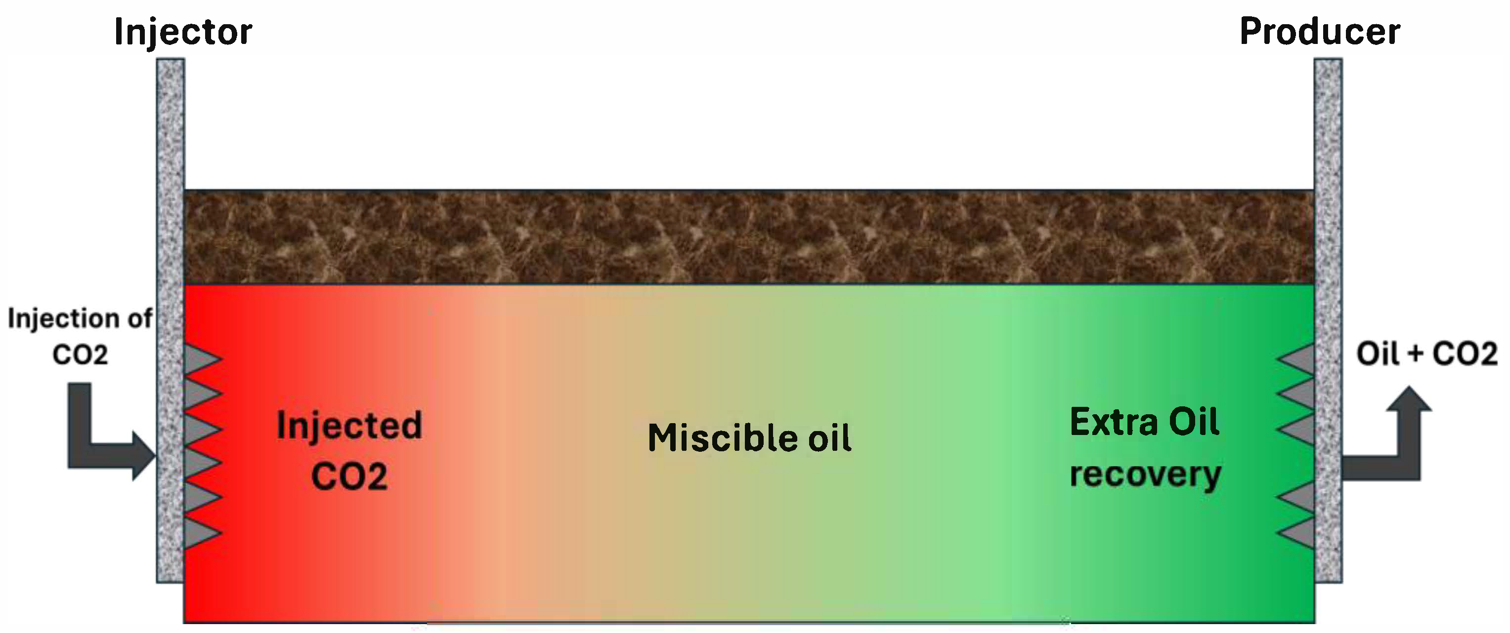
The minimum miscibility pressure (MMP) is the most important factor controlling miscibility. MMP is the pressure below which the injected CO2 achieves miscibility with the oil. Generally, the MMPs for light oils (API gravity above ~30°) below ~2500–3000 ft depth can be reached by available surface supplies of CO2. It is less likely for the injected CO2 to be first-contact miscible. Rather, miscibility occurs through a multi-contact process, where multiple contacts between the CO2 and the oil (in situ) result in the continuous transfer of components (5–8). Initially, the contact between the CO2 and the oil results in the vaporization of the intermediate-molecular-weight hydrocarbons into the CO2 (enriching the CO2), while some CO2 dissolves into the oil. This enriched CO2 phase moves through the porous media, becoming fully miscible with the oil ahead, creating an oil bank with a miscible transition zone between the injection well and the oil bank. This process is described in Figure 1, where the miscible transition zone is generated by the combination of the vaporizing drive (light oil components mobilized by the CO2) and the condensing drive (condensation of the CO2 into the oil) [2,19,38].
The CO2 (left) in contact with the oil (right) forms multi-contact miscibility through the vaporization of the light oil components into the CO2 and the condensation of the CO2 into the oil. This results in a miscible phase between the pure CO2 and the oil in the reservoir. In reality, the pressure at which the MMP is attained is at least the reservoir pressure and ranges between 1200 and 3000 psi (8–20 MPa) for light oils [38,39,40].
If the reservoir pressures are above the MMP, the performance of the CO2 flood can be very high, and it can achieve miscibility in the laboratory slim tube experiment, indicating that it is possible to recover over 95% of the oil in a simulated environment. Field data is equally encouraging, indicating that miscible CO2 floods can achieve an additional 10–20% OOIP recovery. However, in a reservoir below the MMP or in the case of a heavy oil that would never mix with CO2, the process is considered immiscible. In immiscible CO2 injection, the oil and CO2 exist as two separate phases, although the CO2 does dissolve in the oil to a certain extent, causing oil swelling and a substantial reduction in oil viscosity. Oil swelling can achieve 10–30% expansion, and the oil viscosity can decrease by over an order of magnitude in the case of light oils. These two factors increase the displacement efficiency at the microscopic level, even in the absence of miscibility. Additionally, the release of solution gas (if the CO2 pressures exceed the oil bubble point) and the reduction in interfacial tension help in mobilizing the oil [1,2,3,4,17,18,19].
Another aspect of CO2 phase behavior is its relationship with water. CO2 has limited solubility in water (although less than in oil) but can form carbonic acid that can interact with carbonate rock. This is a secondary issue in sandstone reservoirs but can make CO2-rich brine dissolve rock and increase its permeability in carbonates [11,12,13]. This geochemical process can improve injectivity slightly and create additional flow paths; however, over-solubilization is rarely a concern on the time scale of an oil recovery project. More significantly, CO2 is not soluble in a significant amount within the water; therefore, when CO2 breaks through into production wells, it is typically a free gas phase that has to be separated and re-compressed. In fact, CO2 flooding processes are a closed loop; therefore, as much CO2 recycling as possible is practiced, with small make-up rates introduced once a breakthrough has been observed. The recycling component drives phase behavior management because it allows the reservoir to be operated at or near miscibility pressures in order to maximize oil per CO2 injected [21,22,23,24,25].
The displacement mechanism is affected by the presence of gravity and heterogeneity. Because supercritical CO2 is less dense than oil and water, it migrates upward by the process of gravity override [40,41,42]. In the case of a horizontal and homogeneous reservoir, this may lead to the formation of a layer of CO2 on top and oil underneath. In the case of an inclined and highly heterogeneous formation with high-permeability zones, CO2 may finger through the top layers and bypass oil underneath [43,44,45]. This may lead to low sweep efficiency even at high microscopic displacement efficiency. Methods to counter this have been described in the next sections under mobility control [27,28,29].
In general, the process of injecting CO2 can be immiscible as well as miscible. Miscible processes, when the pressure is above the MMP, have nearly ideal displacement because of the absence of interfacial tension and capillary effects. Immiscible processes depend upon the principles of solvent extraction, such as gas drive, viscosity reduction, and oil swelling, which, although not as efficient as miscibility, still have advantages over the WAG process. This will be discussed in the following sections in various reservoirs [45,46,47,48].

3. Applications of CO2 Injection in Different Hydrocarbon Reservoir

3.1. Depleted Oil Reservoirs

The traditional use of CO2 injection is in a depleted oil reservoir, in which a substantial amount of oil has been left as a residue due to primary and secondary recovery methods, typically between 50% and 70% of OOIP. These are typically conventional reservoirs that are waterflooded and hence retain a substantial amount of oil in the pore space that has not been contacted by the waterflooding process. The purpose of CO2 flooding in this reservoir is to exploit this oil and extend the life of the oil field by several years [47,48,49,50].
Preferred reservoirs are medium to light oil, with sufficient depth and pressure for miscibility or at least near-miscibility conditions. Screening criteria have included oil API gravity > 25–30°, reservoir temperatures below ~120 °C (allowing for MMP), and ideally, a homogeneous geology and high permeability [42,43,44]. Most projects have been in dolomite or sandstone reservoirs, at depths between 2500 and 3500 m and containing light oils (30–45° API degrees). As an example, the Weyburn field, a major CO2-EOR project, involves a 30° API oil in a Mississippian carbonate at 1450 m depth, where CO2 from a coal gasification plant has been injected above miscibility conditions. In the United States, the largest number of CO2 floods have been in the Permian Basin of west Texas, where CO2 from nearby domes has been used to enhance depleted oil fields. As of 2020, there were more than 140 operational CO2-EOR projects in the U.S., which produce some 300,000 bbl/day of oil [49,50,51].
The amount of incremental oil recovered by miscible flooding with CO2 in depleted oil fields typically varies from 8 to 15% OOIP over waterfloods. Studies have been conducted on dozens of WAG (water alternating gas) processes in the field, and the results have been an average incremental oil recovery of roughly 10% OOIP, ranging from a few percent to as high as approximately 20% OOIP in favorable instances. For example, an assessment carried out on the performance of 59 projects related to the injection of CO2 showed an average incremental oil recovery of roughly 10% OOIP, with some projects having as much as 17% [1,30,31,32,33,34]. In the Permian Basin, the incremental oil recovery for several floods lies within the range of 5–15% OOIP. The International Energy Agency’s Weyburn Project sought to ultimately attain an additional ~130 million barrels of oil recovery over a period of thirty years by injecting CO2, which works out to an additional ~25% OOIP over previous recovery. The economic importance of such an achievement cannot be overstated, as it effectively doubles the life of the oil field. It must be remembered that the amount of incremental oil recovery for immiscible flooding processes in heavier oil formations is generally smaller (often less than 10% OOIP), as the effectiveness per pore volume of the process is lower compared to miscible flooding% [2,33,34,35,36,37].
For a CO2 flood in a depleted oil reservoir, there are a number of ways in which the process can be carried out. In the first approach, CO2 is injected continuously in a single-phase form, sometimes after a waterflood, until breakthrough occurs in the production wells and beyond. While this approach has been used in earlier CO2 floods, sweep efficiency has sometimes been low, as CO2 tends to “finger” through the oil. In more typical CO2 floods, water alternating gas (WAG) injection is used, in which CO2 injection is followed by periodic injections of water—this enhances sweep efficiency and will be explored in more detail in the mobility control section [28,40]. Other approaches to WAG involve tapered WAG, in which the CO2 component of the water and gas mixture is progressively reduced over the life of the project, and Simultaneous Water Alternating Gas (SWAG) in which water and CO2 are injected in progressively shorter pulses, sometimes continuously together. Another technique, “huff-and-puff”, in which CO2 is injected into a well, held there for a soak, and then returned to production, has also been used, in which the well is placed back into production to allow oil and injected gases to be produced. “huff-and-puff” is also practiced in some unconventional reservoirs, as will be explored in the next section, and in some conventional fields in mature wells [7,34,48].
One of the operational factors in depleted oil fields is the management of the injection pressure. This is done to ensure that the pressure of the injected fluids is greater than the minimum miscibility pressure (MMP) but below the fracture pressure of the reservoir. Injecting fluids above the fracture pressure results in the unwanted propagation of fractures or the reactivation of faults, hence the formation of pathways for the leakage of the CO2. Injecting below the MMP, particularly in the case of lighter oils, results in the loss of miscibility [30,49]. Most of the floods operate close to the threshold of miscibility. For instance, the SACROC CO2 flood was injected at a pressure of about 3000 psi to ensure miscibility. Additionally, in some of the fields, particularly in fields that have low pressure, re-pressurization of the fields, initially with water and some gas, prior to the commencement of the CO2 flood has been done to ensure that the conditions for miscibility are met [19,32].
A second component is produced fluids handling. The produced gas in CO2 floods may contain 20–80% CO2 (after breakthrough), which must be stripped from the oil at the surface. Generally, a low-temperature separator or gas treating plant would remove any liquefied hydrocarbons (if present) and produce a CO2-rich gas [22,41]. The CO2 is then compressed for reinjection. Losses are incurred for small volumes flared/vented and dissolved in produced oils, but an effective flood recovers a great majority of CO2, requiring only small additions. A measure of effectiveness is the Utilization Rate, the amount of net CO2 consumed per barrel of produced oil. CO2 floods historically sought to conserve CO2 use on economic grounds (the cost of CO2 purchase), requiring only 0.3–0.5 metric tons CO2/net barrel of oil. Within the current CCUS context, increasing CO2 storage is viewed positively for greenhouse gas reductions, but economic trade-offs remain since beyond a certain point, more CO2 adds little incremental oil [31,45,46,47].
CO2 flooding in conventional oil reservoirs is a proven process for incremental recovery gain. Various field demonstrations have confirmed the capability of CO2 miscible displacement processes for recovering about one-tenth of additional OOIP, which can mean tens of millions of barrels on a massive scale. The next application involves a different situation: CO2 flooding for recovery gain of natural gas from a depleted gas reservoir [27,37,38,39].

3.2. Depleted Gas Reservoirs (CO2-Enhanced Gas Recovery)

In addition to oil, CO2 injection can also be used in gas reservoirs after gas depletion for the extraction of additional gas, a process also known as CO2-enhanced gas recovery (CO2-EGR). When a gas reservoir has been produced through primary production, a large amount of methane can be left within the pores at reduced pressure. When CO2 injection takes place, it can increase the pressure within the gas reservoir, which will force the remaining gas towards production wells as a secondary process, while at the same time the CO2 will be used as a cushion gas, which will be trapped within the formation [23,24,25,35].
The process in gas reservoirs is relatively simple: CO2, which is generally denser than methane, is injected, usually at the periphery or at the bottom of the reservoir, pushing the remaining methane towards the producers by displacement. Miscibility is not an issue here, unlike in an oil reservoir, since CO2 and methane are miscible in all proportions (they form a single gas phase at reservoir conditions). Thus, only pressure and volumetric sweep are of interest [44,45,46]. CO2-EGR can also be likened to a waterflood in an oil reservoir, where the “water” is CO2 and the “oil” is methane. The design considerations include injection rates, injection well locations relative to producers, and gas composition changes [45,46,47].
It has been found that CO2-EGR can result in a substantial enhancement of gas recovery remaining in reservoirs. For instance, a review of studies on CO2 injection in depleted gas reservoirs demonstrated that it could increase the gas recovery factor by as much as several tens of percent compared with depletion recovery alone. In a specific example, injecting CO2 increased recovery factor by ~18 percentage points, reaching a value of over 53% of original gas in place compared with ~35% by depletion alone [5,31,32,33]. Laboratory-scale core flooding and modeling studies also demonstrated increased gas recovery with, for example, core flooding tests on low-permeability sandstone increasing gas recovery from 64% to ~93% with CO2 injection. Feasibility studies at a larger scale, mostly simulation studies at this stage, indicate that between 60% and 80% of the remaining methane could be recovered with optimized CO2 flooding strategies. Real-scale pilots are limited, although a Kevin Dome and current tests at the German gas field of Altmark are two projects that demonstrated increased gas recovery and large CO2 storage potential in a partially depleted gas reservoir [4,16,17,18].
One of the major pluses about CO2-EGR is that the structural integrity of the depleted gas reservoirs, which were able to hold gas for thousands of years, can be used for the pore volume capacity once the methane gas is harvested. This essentially means that the depleted gas fields are amongst the safest and most massive capacity sites for storing CO2. Economic calculations also state that the incremental gas produced can help defray some of the costs involved in the CO2 injection operation. If 10–20% extra gas can be harvested, it can help defray the costs of CO2 compression and drilling [20,21,22,23].
There are, however, some technical considerations that are gas reservoir-specific. These include gas mixing and purity. Since CO2 forces methane towards the producers, some CO2 is bound to come along (particularly after the breakthrough point is reached) [22]. Consequently, the produced gas composition could be a CO2 and CH4 mixture. If this gas is intended for pipeline sales, a high CO2 concentration is problematic (pipeline sales specifications usually limit CO2 to <2–5%). Consequently, surface separation units or gas processing plants (such as amine treating, membranes, and others) could be necessary to remove CO2 from the sales gas [25,26,27]. These could include the following options: Inject CO2 through the use of EGR towards the end of the reservoir’s lifespan and stop production when CO2 breakthrough becomes unmanageable, thereby leaving a CO2-rich gas in the reservoir as the trapped gas. In this case, some gas producers could potentially stop production just before the CO2 breakthrough and thereby sequester the CO2 and methane gas mix in place. Another option would be to have a gas plant nearby that can strip the CO2 and recycle it for reinjection [26,27,28,29].
Another aspect to consider is the management of reservoir conditions. In contrast to oil, methane does not have the advantage of viscosity reduction and therefore relies on pressure drive. Hence, CO2 injection would require re-pressurization of the reservoir to nearly original reservoir pressure to mobilize additional volumes of gas. This would require substantial volumes of CO2. In addition, if the reservoir had strong aquifer drive support in its depletion history, some parts of the reservoir would be filled with water, and CO2 would have to drive out the water as well (essentially CO2 storage with minimal productive benefits in these areas). Another aspect that can be utilized in reservoir management is the use of gravity segregation in dipping reservoirs. CO2, being heavier, can be injected in the downdip part of the reservoir so that it migrates upwards and mobilizes methane towards the producers in the higher structural parts of the reservoir. In fact, it has been found that CO2 injected at the bottom of the core (to simulate the dipping reservoir) resulted in an additional recovery of 5 to 8% of extra gas in comparison to top injection [31,32,33,34].
Lastly, CO2-EGR needs to take into account rock–fluid interaction in some instances. In traditional sandstone or carbonate gas reservoirs, there will be little chemical interaction between CO2 and rocks, aside from potential carbonate dissolution (in the presence of water), which is similar for CO2-EOR. However, when considering more general EGR applications for unconventional gas, such as shale or coal gas (which will be covered in subsequent sections), rock–fluid interaction becomes significant, particularly for adsorption. In traditional depleted gas reservoirs, mineral scale formation is a potential problem, and this can be exacerbated by CO2, which can reduce pH and lead to potential formation of carbonates or sulfates, depending on incompatibility of mixed fluids. In fact, laboratory studies have shown that in high-salinity water Alternating Gas, calcium carbonate or sulfate formation can be expected, although at 93 °C it was observed that there was only a 10% reduction in permeability, and at lower temperatures, there was even less effect. In summary, traditional gas reservoirs present little complexity for CO2 injection on geochemical grounds [41,42,43,44,45,46,47].
In short, the injection of CO2 into gas-depleted fields is a promising CCUS method because it has the potential for both methane and CO2 storage. Simulation results and initial tests have revealed considerable increases in gas recovery (in tens of percentage points of GIIP) and have proven the feasibility of the massive CO2 storage in depleted gas fields. This is because the production management concerning CO2 contamination and the gas processing step has high importance in the implementation of the method. The following section discusses the injection of CO2 into the unconventional oil fields because of the challenging mechanisms involved [43,44,45,46].

3.3. Unconventional Reservoirs (Tight Oil and Shale)

The permeability in tight oil reservoirs, as well as shale reservoirs, is very low (micro- to nano-Darcies), which translates to very low primary recoveries (<10% OOIP, with some being 1–5% only). Due to the recent shale oil boom, there is great interest in techniques that could enhance recoveries from such reservoirs above what is possible with the help of horizontal drilling and fracking. CO2 injection has been identified as an attractive EOR process for shale reservoirs, although its application is completely different from that in conventional reservoirs [50,51,52,53].
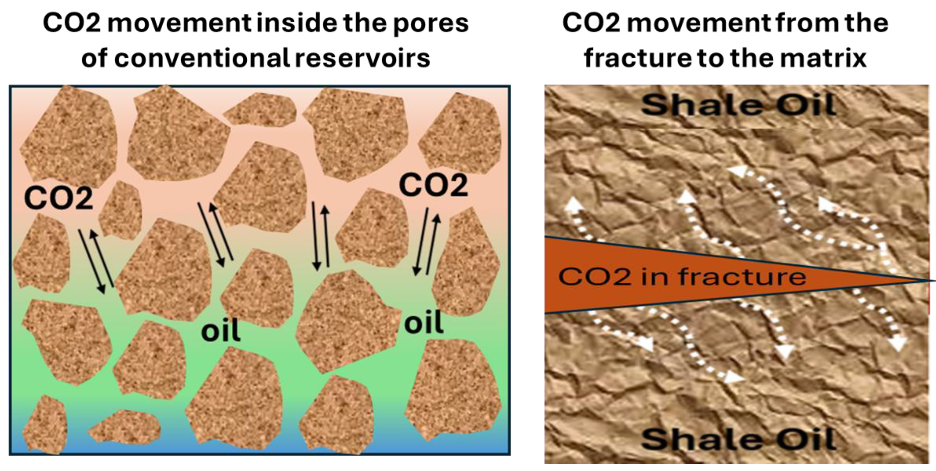
Mechanism in Shales: In reality, CO2-EOR in shale/tight oil reservoirs is normally carried out through the huff-and-puff (cyclic) mode in individual wells, and not through the conventional flooding pattern, since it is difficult to establish injectivity and inter-well connectivity in nano-perm rock. In a CO2 huff-and-puff, a well is switched among the injection stage (where CO2 is injected into the reservoir fracture network), a soak stage (where the well is shut-in to permit CO2 to migrate into the matrix), and a production stage (where the well is opened and produced to extract oil and a small amount of CO2) as in Figure 2.
These stages can be repeated numerous times [54,55,56,57]. The oil recovery mechanisms in CO2 flooding in shales include a number of the same processes in conventional reservoirs, although with a different set of priorities:
  • Molecular Diffusion: CO2 diffusion can occur in the tight matrix of shales, reaching the oil that was not accessed by the primary flow. CO2 enrichment of the oil phase can occur in the matrix with sufficient soaking time, causing swelling of the oil that is trapped. Since diffusion is the main process that occurs in shales because of their small pore sizes, diffusion determines the extent of CO2 that diffuses from the fractures into the matrix blocks [53,54,55,56].
  • Oil Swelling and Viscosity Reduction: Similar to conventional reservoirs, the dissolution of CO2 in the shale oil results in the swelling of the oil, making it less viscous. This helps the oil move back into the fractures due to the pressure gradient when the well is opened. Since tight oil tends to be lighter crude (API 35° to 50°), the addition of CO2 can reduce its viscosity significantly (e.g., Bakken viscosity could decrease from 2 cP to less than 1 cP upon saturation with CO2) [57,58,59].
Pressure Recharge (Depressurization Drive): The injection of the CO2 re-pressurizes the formation in the vicinity of the wellbore. Later, during the return to production, the increased pressure gives an additional push to the oil (especially the oil below the bubble point, which lost solution gas drive during primary depletion). The artificial drive mechanism from the injection of the CO2 may result in a blowdown (also referred to as “re-pressurize and produce,” which releases the hydrocarbon resources as in a secondary depletion) [55,56,57,58].
  • Oil Vaporization and Extractive Processes: CO2 is capable of extracting the lighter hydrocarbon compounds present in the oil by vaporizing them into the CO2 phase. There may be an appreciable amount of intermediate hydrocarbons and gas liquids in shales. These may be removed by contact with CO2. As the gas is produced in the well, a gas phase rich in CO2 is released with the light compounds (compare condensing/vaporizing drive) [51].
  • Adsorption Effects: Organic materials may be present within shale rock that may adsorb hydrocarbons. This may happen because the CO2 may selectively adsorb on the kerogen or clay surfaces, thereby displacing the already adsorbed oil or gas. This may lead to the release of additional hydrocarbons for extraction. Although the process of adsorption occurs in shales, it is not significant like the process occurring in coals [52].
These mechanisms have been proven by laboratory experiments as well as simulation studies. For instance, core-scale experiments carried out on the Eagle Ford shale indicated that CO2 huff-and-puff could potentially mobilize oil even at a very low-perm rock, resulting in as much as 65–85% incremental oil recovery over baseline values at times. Modeling of the process of diffusion shows that the soaking time as well as the fracture interval play a pivotal role, with longer soaking time as well as smaller fracture intervals facilitating greater interaction between the CO2 and oil. An important aspect of this process is the principle of diminishing returns, where each subsequent huff-and-puff cycle contributes less towards increased production as a whole [57,58,59].
Field Pilots: There have been a few pilot projects reported for CO2-EOR in shale, although these projects are still in the experimental phase. In the Bakken shale play in the Williston Basin, U.S., a few single-well CO2 huff-and-puff pilots have shown incremental oil and have yielded information related to injectivity and CO2 utilization. In one such pilot, for example, CO2 was injected at rates of a few hundred to a few thousand cubic feet of gas per day for several weeks, and this was followed by increased oil production when the well was turned back online. The injection pressures were reported to be in the range of a few thousand psi to force the CO2 into the shale matrix. The pilots have been a mixed bag, some having shown positive, although small, oil production, while others have performed below expectations. One such experience has been early CO2 breakthrough along fractures without effectively displacing the shale oil, which results in higher CO2 production and less associated oil, although this was not expected. Numerical simulations, employing state-of-the-art methods such as EDFM, which model fractures explicitly, have been used to interpret these pilots. EDFM simulations have indicated that CO2 huff-and-puff could potentially be applicable in shales with porosity values in the approximate range of 4% to 10% and permeability values in the microdarcy ranges, although these processes have been very sensitive to fracture spacing and matrix diffusion rates. Additionally, these simulations have suggested that a simple dual-porosity model could potentially over- or under-predict these results if it does not capture the complex multicomponent diffusions and adsorptions accurately [53,54,55,56,57,58].
Notable Findings on Mechanisms: it is noted that in shale CO2-EOR processes, molecular diffusion and soaking time are of prime importance because CO2 requires some time to diffuse into the matrix. They have identified molecular diffusion, viscosity reduction, swelling of oils, depressurization, and, finally, extraction as the basic processes in shale reservoirs. This can result in overly optimistic or pessimistic results if these basic principles are misunderstood. For instance, in some cases, the results in the field have turned out worse than in the lab because in the lab it is possible to have prolonged exposure times [42,43,44,45].
Recovery Potential: How much additional oil could CO2-EOR possibly extract from shales? It is still unclear, but perhaps an additional few percentage of OOIP recovery could be possible. Primary recovery is about 5%; perhaps CO2 could offer an additional 5–10% recovery in a best-case scenario (total doubling recovery). Some modeling studies for the Bakken have indicated that perhaps an additional 5 percent of OOIP recovery could be possible with a multi-well huff-and-puff process. In one instance, a total recovery of 15% OOIP (compared with 5% primary) recovery was forecasted. However, such high figures have yet to be realized by actual field trials, with a difference between laboratory and field data as indicated by the literature [55,56,57,58,59,60].
  • Operational Challenges: These will be detailed in the section below, but some examples of those that pertain specifically to unconventional CO2-EOR include the following: The injection of CO2 into a very tight rock formation requires either access via existing fractures or creating new ones (CO2 can re-fracture or extend existing fractures under high pressure injection conditions). The ability to control CO2 conformance in a complex fracture scheme can be problematic—CO2 can flow along a few main fractures and bypass most of the matrix altogether. Additionally, you have to have access to large quantities of CO2 and have a means of compressing and distributing it at many wellheads across a shale pad, which can be a significant logistical undertaking. Also, shale–fluid interaction issues can be present—for example, CO2 can cause asphaltene precipitation or cause water (from fracs) to precipitate and can cause fines migration, which remains an ongoing subject of investigation [22,23,24,25,26,55].
In conclusion, CO2 injection in tight oil/shale formations represents a new and active topic in EHR. The mechanisms involved (diffusion-driven multi-contact miscibility, pressure buildup, etc.) are well understood from a qualitative perspective, and laboratory experiments indicate high potential for oil mobilization. Pilot-scale experiments in the field have confirmed the possibility of producing some additional oil, although further optimization is required. When cracked, CO2-EOR may potentially offer a significant enhancement to the total recovery of oil in shale formations, as there are currently tens of billions of barrels of oil in place, bypassed by primary production [42,43,44,45,46].

3.4. Applications in Coalbed Methane (CO2-ECBM)

Another unique use of CO2 injection is in unmineable coal seams for the purposes of improved methane recovery, which is termed CO2-enhanced coalbed methane (CO2-ECBM). Coalbed methane (CBM) reservoirs contain a substantial volume of natural gas (CH4) in the form of an adsorbate in the coal matrix, primarily because of adsorption on the internal surface area of the coal. Primary recovery of CBM occurs because of pressure depletion, which leads to desorption of methane. However, only 50% or less of the in-place methane can be recovered by primary recovery methods. CO2 injection can be used for enhanced recovery of methane as well as for sequestering CO2 because of differences in adsorption preferences in coal [61].
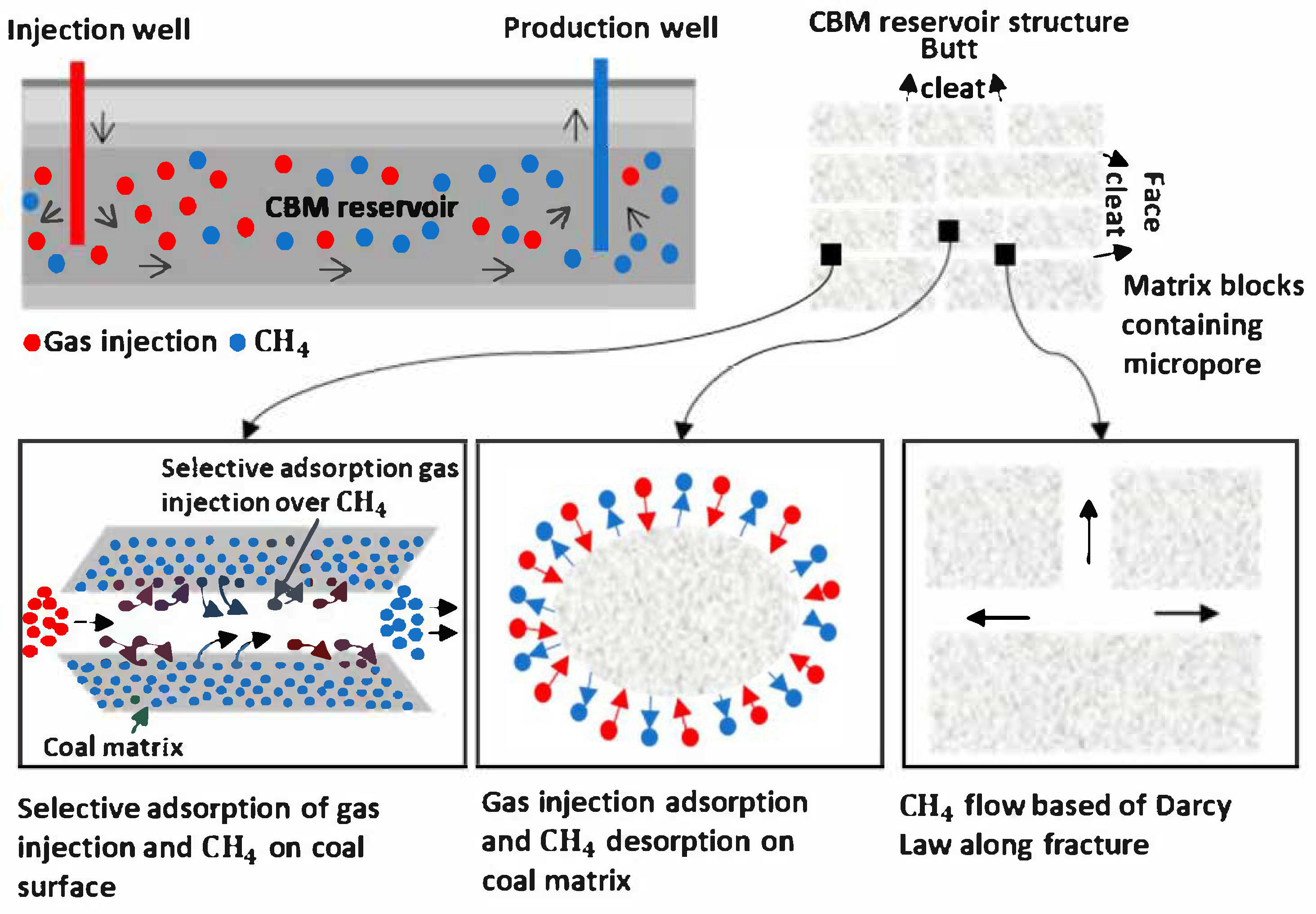
Mechanism: Coal has an interesting behavior in that it adsorbs more CO2 gas than methane, and it does so more strongly and in larger quantities. In fact, CO2 can more easily, or at least twice as easily on a molar basis, adsorb on coal than CH4 can. Therefore, when CO2 is pumped into a coal seam, it has a tendency to push methane molecules away from the coal surface—CO2 occupies the adsorption sites, and methane molecules are then free to move into the pore space and flow away as free gas that can easily be extracted at a production well. In effect, CO2 injection starts the flow of methane from the coal seam. At the same time, the coal seam becomes a sponge that captures CO2 and transforms it into a solid material attached to coal particles, which remains there for an extended period of time—effectively achieving permanent CO2 sequestration on a geological scale, which makes this technology very attractive from a CCUS point of view and explains why it has attracted so much attention and investment recently. All this is shown in Figure 3, which illustrates how CO2 molecules (blue) pumped into the coal seam adhere to pore walls, releasing methane (red) that then flows into a production well [61,62,63].
This is confirmed by empirical evidence from laboratory and pilot testing. The coal adsorption isotherms demonstrate, for instance, that for a given pressure, coal can adsorb approximately 10 SCF/ton of CO2 compared with approximately 5 SCF/ton of CH4, indicating the stronger affinity for the former. Field pilot tests (at the Allison Unit, San Juan Basin, NM, USA) confirmed that the injection of CO2 can lead to the production of additional methane, which could not be obtained by primary depletion alone. Laboratory core flood experiments have indicated dramatic increases in the efficiency of methane recovery, from approximately 66% for primary depletion to over 90% after primary depletion with the injection of CO2 for a bituminous coal sample. In other words, the CO2 forced out almost all the remaining methane [62,63,64].
  • Operational Methodology:
The operational methodology of CO2-ECBM typically involves the injection of CO2 into some wells and gas production at other wells, typically following a flood pattern, usually a line drive or a 5-spot pattern for a coal seam. The injected CO2 will migrate along the cleats (natural fracture systems of the coal) and diffuse into the coal matrix, where it will be adsorbed. Then, desorbed methane will diffuse into the gas phase and migrate along with the gas towards the producer wells. Since the permeability of coal is relatively low (and also stress-sensitive), injection at a higher rate might be difficult. Occasionally, a “soak” or “huff-and-puff” process might be used, but typically, ECBM operations can be viewed as a continuous flood process for maximizing CO2 storage [62,63,64,65].
  • Challenges
Coal Swelling: One of the big concerns with CO2-ECBM is that as CO2 adsorbs on coal, coal swelling occurs. This is more or less the opposite of what happens during primary CBM recovery, where coal shrinkage is accompanied by increased permeability as methane is desorbed. While coal swelling due to CO2 adsorption may reduce porosity and permeability, thereby inhibiting gas movement, it is possible to see more than 50% reduction in permeability, thereby inhibiting injectivity as well. This is what happened during the Allison Unit pilot, where initial injectivity rates decreased as coal swelling occurred due to CO2 adsorption, thereby blocking gas flow. While it is necessary to control injection pressure to prevent excessive CO2 adsorption at a particular location, it may also be necessary to inject a gas mixture, such as N2, to control swelling. N2 does not adsorb much, thereby keeping coal porosity open. In fact, some ECBM projects inject 50% CO2 and 50% N2 to prevent swelling [63,64,65].
Field Experience: The Allison Unit pilot (1990s, San Juan Basin) was the first and only full-field test of CO2-ECBM. It entailed injecting approximately 80 BCF of CO2 over several years into a coal panel and assessing the methane production response. It did verify an increased methane production rate (factor of 2 for the first gas production rate and an estimated 25% increased ultimate methane recoverability over the life of the pilot). Nevertheless, issues such as injectivity reduction (swelling and perhaps water blocking) and CO2 breakthrough to the producer wells existed. As for economics, it was marginal considering the CO2 cost and the then-existing gas prices. Since then, smaller-scale pilots have taken place in the province of Alberta in Canada, as well as Japan. These verify the technical feasibility of the process: CO2 seeps into coals and releases methane. Nevertheless, they also verify the observation that without carbon credit economics, ECBM is not particularly economic on the basis of methane production alone—the methane price typically does not pay for the CO2 cost of purchase and injection [62,63,64,65].
Present Scenario: The CO2-ECBM process is presently being considered a prospective double-duty technology for both enhanced gas recovery and CO2 storage. The estimated capacity of unmineable coal seams globally could potentially store between 200 and 300 Gt of CO2 along with considerable quantities of methane. The technological advancements being explored include the application of CO2 foam or CO2-soluble surfactants to enhance the distribution of CO2 within the coal seams, such that it does not preferentially follow a few flow paths, and the injection of alternate N2/CO2 to control swelling. There have also been suggestions of pre-processing the coal, for instance, by solvent or thermal methods, to make it less prone to swelling or to enhance its permeability before CO2 injection [61,62,63,64].
In conclusion, CO2-ECBM utilizes the strong adsorption of CO2 on coal to yield more methane. It has been shown to work in principle—CO2 can increase methane extraction by 90% compared with 60% without CO2 and also sequesters large volumes of CO2 in the coal. The challenge comes in ensuring that the process remains economical and that the permeability of the coal is maintained. Carbon credits for CO2 sequestration or CO2 pricing would certainly make ECBM economical, making uneconomic coal seams new gas producers and CO2 repositories [63,64,65].
A comparative chart of CO2 injection applications on various reservoirs is given in Table 1 below.
The following is a summary from Table 1 about the customization of CO2 injection according to the reservoir conditions with expected mechanisms and difficulties for each case. With this background on CO2 sweep application, the next part focuses on the development of technologies related

4. Mobility Control Technologies

However, one of the main difficulties associated with CO2 flooding is the low mobility ratio between CO2 and other fluids within the reservoir. The supercritical CO2 has low viscosities (typically 0.03–0.1 cP) relative to those of oil (1–10+ cP) or water, with a density less than that of water. This is expected to result in viscous fingering, channeling, and gravity overriding, where CO2 floods past a significant portion of the oil, resulting in early breakthroughs at production wells with low volumetric sweep efficiencies. However, several techniques have been employed as a remedy for this issue associated with CO2 flooding. These are discussed as the following section on mobility control: water alternating gas (WAG) processes; foam-assisted CO2 flooding (FAWAG/SAG processes); polymer-enhanced CO2 flooding; and CO2 low-salinity flooding processes [66].

4.1. CO2 WAG (Water Alternating Gas) Injection

Water alternating gas (WAG) is the most mature technique of the three for mobility control during CO2 flooding. During a WAG process, a slug of CO2 is injected followed by a slug of water, then another slug of CO2, and so on. The idea was field-tested in the 1950s at Pembina, Canada, and the thought behind this process is that the water helps control the mobility by banking on the CO2, pushing it ahead more evenly, with the gas mobility being decreased by banking some of the CO2 into the pore space due to relative permeability. Effectively, the injection of water after the CO2 forces the CO2 away from the high-permeability zones into the lower-permeability zones that the water occupies [42,43,44,45].
The WAG process has been applied in most of the large-scale CO2-EOR projects. It is attributed a 5–10% OOIP incremental oil recovery gain over what could be achieved by continuous CO2 injection. Analysis of 60+ field cases indicated that WAG resulted in an average oil recovery gain of approximately 9.7% OOIP compared with waterflood alone. In addition, WAG has been observed to greatly extend breakthrough and retention of CO2. For instance, in a test in a Canadian field, breakthrough of continuous CO2 injection was rapid, whereas a 1:1 WAG resulted in a later breakthrough and increased oil recovery [43,44,45].
Critical design considerations in WAG are the WAG ratio (volume of water injected per volume of gas), and the size and number of cycles of the slug. Typically, the WAG ratio can vary in the range of 1:1 or 2:1 (water to gas) in terms of pore volume. More frequent and smaller cycles of the slug are generally more efficient in terms of mobility, although this is at the expense of the operation becoming more complex, whereas larger cycles of the slug are less complex in terms of operation, although less efficient in terms of mobility control. Simulation and research studies suggest that the optimal WAG ratio is generally 1:1, with multiple cycles, in order to achieve the highest possible recovery, although this is dependent on the reservoir characteristics studied. Skauge et al. suggest that multiple short cycles of WAG are generally superior to a single gas cycle followed by a single water cycle, since this ensures a uniform distribution of CO2 in the reservoir, regardless of the amount of CO2 in each cycle, although the cycle of WAG can vary in the range of 0.1 to 0.3 pore volume of CO2, alternating with a similar volume of water [62,63,64,65].
Performance and Problems: Although WAG has been shown to be highly effective, it also has some problems. For example, even when using WAG, gas channeling can be a problem in heterogeneous or fractured reservoirs, where water might not fully plug the high-perm zones, particularly in fractures where gravity segregation might allow gas to bypass water [44,45,46]. On the other hand, using WAG will also increase the complexity of the operation, since injection wells will be required to inject gas as well as water, or a conversion process might be needed at the wells or surface facilities [63,64,65].
The quantitative improvement in oil recovery achieved by the WAG projects includes an improvement in the range of 5–15% OOIP as stated, as well as an improvement in the amount of CO2 used per barrel of oil. For example, a typical waterflood might have been stopped at 30% OOIP, but the CO2 WAG might have increased it to about 40% OOIP, whereas without the WAG process, the CO2 might have reached only 35% at a much higher rate of production [46,47,48,49].

4.2. Foam-Assisted CO2 Injection (FAWAG and SAG)

CO2 foam injection is the process of injecting a surfactant (foaming agent) and CO2 (or alternating with CO2) to form a foam in place in the reservoir. CO2 foam is a dispersion of CO2 gas in a water–surfactant solution in the form of small bubbles of gas. CO2 foam can substantially increase the apparent viscosity of the CO2 gas and block the highly permeable pathways by forming gas bubbles, thus enhancing sweep efficiency. CO2 foam can be implemented in either foam-assisted WAG (FAWAG), where a foam is produced in the gas cycle of WAG, or in Surfactant Alternating Gas (SAG), where the surfactant solution and gas alternate [1,2,3,4].
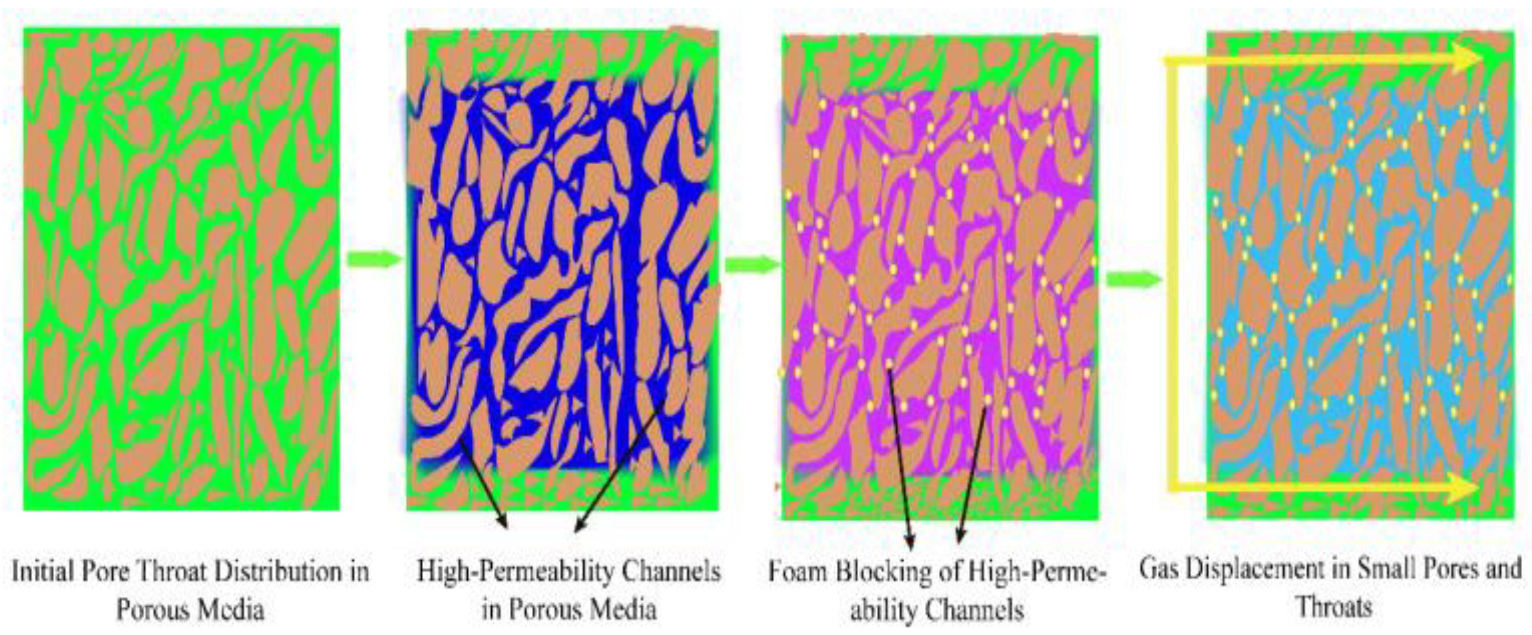
The impact of foam can be expressed in terms of the Mobility Reduction Factor, in that foam can decrease gas mobility by an order of magnitude or more. As foam intro-duces a distributed resistance in the reservoir, it causes the CO2 to move into the smaller pores, as opposed to the gas moving in the “thieves” in the case of the conventional process. Laboratory core floods have indicated that the diversion of flow, as well as the mitigation of gravity override, can be achieved significantly by the CO2 foam. For instance, in the FAWAG pilot in the North Sea (Snorre field, 1990s), the injection of the CO2 foam led to the increased recovery of oil by around 5% of the STOOIP, against the expected values, as well as a decrease in gas production rates.
A recent review indicated that the injection of a gas-phase foam during WAG led to an incremental recovery of around 5% of OOIP over conventional WAG. Also, FAWAG pilot data analyses performed on a carbonate reservoir in the Middle East indicated that the process led to higher rates of recovery than CO2 flooding alone, on account of the foam’s ability to plug override zones. A comparative study indicated that FAWAG led to a total recovery of 92% of movable oil compared with 88% for SWAG (simultaneous WAG) and lower for CO2-WAG [64,65,66].
How Foam is Implemented:
  • There are several methods—(1) Co-injection: simultaneous injection of surfactant solution and CO2 (can be pre-formed at the surface or allowed to foam at the bottom). (2) Surfactant slug then CO2 (SAG): surfactant solution in water slug, then chase with CO2; as the front of the CO2 reaches the surfactant solution, the solution foams. (3) Small cycles with surfactant in water, similar to WAG [46].
  • Each process has advantages and disadvantages. Co-injection allows constant foam generation but requires a mixing facility, while SAG requires less equipment but allows foam generation mainly at the displacement front [49].
  • Advantages: It can significantly decrease the mobility of the gas—a mobility reduction factor ranging from 10 to 100 times has been observed on cores. It can move the gas from a high-perm area into a low-perm area and can prevent gravity segregation by creating a “foam blanket” that sustains the gas phase. In a fractured reservoir, foam can move into the fractures and decrease their ability to transmit fluids by a significant extent (this is known as “thermodynamic trapping by the Jamin bubble effect”). This forces CO2 into the matrix blocks, bypassing the CO2 that tends to “short circuit” along fractures.
  • Field/Pilot Results: On other projects, foam injection increased sweep in a highly fractured carbonate in the Middle East on the Dalphin FAWAG project, with an incremental 4% OOIP oil. An SPE case from Algeria described how foam injection in a CO2 flood increased oil flow rate and reduced gas–oil ratio greatly compared with WAG before foam. Additionally, foam pilot projects in SACROC retarded the onset of CO2 breakthrough [56,57,58,59].
However, the limitations of the foam process include the following:
  • Foams are thermodynamically unstable mixtures and may break because of oil (oil depresses the films of the foams), high-salinity water, and high temperature. Foams may therefore be ineffective in high oil saturation at the displacement front and in high-salinity brines. Also, foams require the presence of water. This means in a near-miscible flood process in which everything was dried out, foams may not be formed. There is also the challenge of high sorption of the surfactants on the rock. This means that some of the expensive surfactants may be sorbed into the rock [55,56,57,58].
  • Despite these, methods have been developed to enhance foam resilience through the use of nanoparticles or polymers as foam stabilizers. The inclusion of nanoparticles, such as silica, improves the stability of the foam against oil and high temperatures by strengthening the lamellae. The addition of polymers enhances the foam’s liquid phase, which reduces drainage and prolongs the foam’s life. The polymer-stabilized foam, or polymer-enhanced foam (PEF), has demonstrated high stability in lab experiments, with foams surviving for several days [57,58,59,60].
  • To sum up, CO2 foam (FAWAG/SAG) is an effective tool for mobility control, which, when applicable, can greatly enhance CO2 flood sweep efficiency. It can be particularly effective in heterogeneous and fractured reservoirs, where conventional WAG might fail. There have been several pilot projects and full-scale applications that have confirmed this technology, although it requires careful planning in terms of foam stability for specific conditions of a reservoir [50,51,52,53].
In high-permeability streaks or fractures as shown in Figure 4, CO2 will move upward in channels, leaving the oil behind (left). In contrast, with foam (right), CO2 gas and surfactant solution create foam bubbles that plug the larger channels and drive CO2 into the smaller pores to better sweep the unswept oil. Foams can counteract the effects of gravity override and viscous fingering to provide more equal displacement of the oil towards the producers. Note that it is important that the foam remains stable; this has been achieved in recent methods by employing nanoparticles or polymers to fortify the foam films [1,2,3,59].

4.3. Polymer-Assisted CO2 Flooding (Polymer WAG)

Polymers (usually hydrolyzed polyacrylamide or biopolymers) may also be added to the water phase of the WAG process to increase the viscosity of the water phase and hence the mobility ratio between the water phase and the oil phase. In the case of CO2 flooding processes, the addition of polymers to the WAG process, where the water slugs of the WAG process contain polymers, is referred to as the polymer-assisted WAG process or P-WAG/PWAG process. This process is beneficial because the polymers will make the water phase more effective at displacing the oil phase because the high-viscosity fluids move at slower rates; thus, the water phase will not finger into the oil phase easily. Additionally, the high-viscosity water phase will act as a buffer between the gas phase and the oil phase; thus, the gas phase will move at slower rates because the high-viscosity water phase acts as a barrier between the gas phase and the oil phase. This means that the addition of polymers will make the “water phase” of the WAG process more effective at both displacing the oil phase and mobilizing the gas phase because the high-viscosity fluids will trap the gas phase better [46,47,48,49].
Another similar process is the polymer-enhanced foam process or PEF process where polymers and foams are added; however, this process will not be considered.
Simulation and field trials indicate that polymer WAG may offer much higher recoveries than WAG. For instance, a simulation carried out on the North Burbank Unit demonstrated that an improved WAG process could recover approximately 20% OOIP compared with 8% for the WAG process in the given case. This is an enormous difference (notwithstanding the fact that the rock was highly heterogeneous, so the basic WAG process was not very effective). For highly heterogeneous rocks with permeability above 500 mD, the addition of the polymer to WAG increased recovery by 7–15% compared with WAG without the polymer [67,68,69].
Laboratory core flood experiments also show the effectiveness of polymer in water in overcoming the MPF problem in WAG processes because polymer helps reduce the relative permeability hysteresis phenomenon by maintaining the water phase in a more stable state and by preventing the fast propagation of gas in the gas injection cycles. This results in higher oil displacement per cycle. Polymer also helps in maintaining the production gas–oil ratio by lowering the gas relative permeability in the production phase (if the polymer is in the liquid phase in the reservoir, it helps in trapping the gas) [43,44,45,46].
Considerations:
  • The implementation of polymer-WAG requires facilities for mixing and injection of polymers.
  • Polymers can degrade due to high temperature, salt, or shear.
  • Most CO2 fields remain relatively cool (<120 °C) and will be non-damaging to polymers.
  • Polymers must be selected so as not to react with CO2 or the precipitants.
  • CO2 itself will not damage the polymer, but the produced water chemistry may be a problem (e.g., high hardness will cause some polymers to precipitate).
Examples From the Field: Full-field projects are rare, and a very early example of a CO2 flood that used polymer gels in injection wells to shut off high-perm zones and also polymer in water to enhance sweep is the Salt Creek field in Wyoming, USA. It was said to greatly reduce CO2 cut in producers and increase vertical sweep. Another example is a pilot at Bell Creek field in Montana, USA, that used simultaneous injections of polymer and CO2 to manage a thief zone. More recent work has been done in China on thickened water slugs of polymers in CO2 floods at Daqing oilfield with some success at managing breakthrough [41,42,43,44,45]
Results: Successful polymer flood-enhanced CO2 floods result not only in increased oil recovery but also in an improved CO2 utilization ratio (lower amount of CO2 generated per barrel). The example simulation run from North Burbank showed that the OOIP recovery by polymer WAG was 12% higher than by WAG. In this instance, the possible improvement by regular WAG might be ~8% and by polymer WAG ~20%. Although this particular outcome depends on the circumstances, it does illustrate that in a leaking, heterogeneous formation, the presence of polymer may render CO2 flooding feasible even if otherwise unfeasible. According to a report by the DOE, the use of polymer might extend the application of CO2-EOR to some shallow, viscous oil formations unsuited for miscible flooding with CO2 by making possible an immiscible flood with polymer to manage mobility [35,36,37,38,39].
In conclusion, the synergy between CO2 flooding and the polymer flooding technique (well-established in chemical EOR in waterfloods) is certainly possible. In WAG processes, the addition of polymers to the water can increase the sweep efficiency by reducing the chances of CO2 bypass by increasing the viscosity of the fluid. This technique would be particularly useful in cases of heterogeneous reservoirs with fractures or thief zones where the water in conventional WAG processes can be too mobile to act as an effective barrier to CO2 [36,37,38,39].

4.4. CO2 with Low-Salinity Waterflooding (CO2-LSWF and LSWAG)

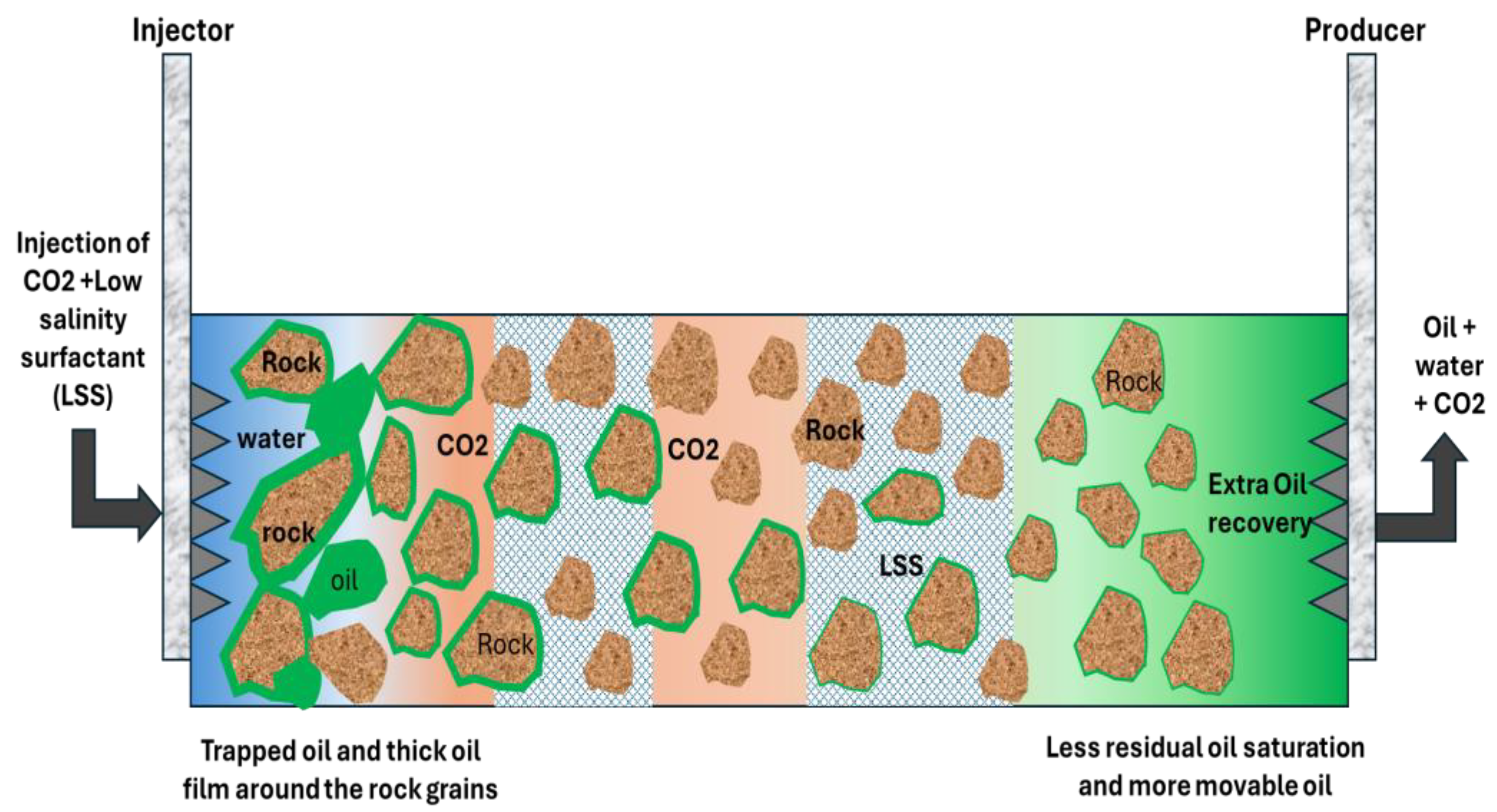
As shown in Figure 5, low-salinity waterflooding (LSWF) is an EOR technique where the salinity and ionic strength of the injected water are tailored (typically much lower than the formation water) to enhance oil recovery through wettability modification and other physico-chemical mechanisms. There has been recent interest in the combination of low-salinity waterflooding with CO2 flooding, either in a sequential manner or concurrently, to reap the synergies from the two approaches. This combination technique is sometimes referred to as CO2-LSWAG (low-salinity water alternating gas), while other times it is simply referred to as CO2-LSW flooding [24,25,26,27].
The aim is that low-salinity fluids can increase the efficiency of the microscopic sweep through the modification of rock wettability towards a more water-wet surface and the mobilization of additional oil through multicomponent ion exchange, whereas the CO2 contributes the miscible/immiscible solvent and the macroscopic sweep, particularly in WAG processes. There are a number of proposed synergies:
  • Low-salinity water may result in the formation becoming more water-wet, hence less residual oil saturation before or at the time of injecting the CO2, making the process of displacing the oil by the CO2 easier.
  • A low-salinity brine can slightly increase the solubility of CO2 and reduce the chances of salt precipitation (dry-out) during CO2 injection, which can help in mobility control of CO2, and the stability of CO2 foam is also enhanced by a lower salinity, if foam is generated.
  • For LSWAG processes, where low-salinity water is alternately injected along with CO2, not only is mobility control provided by each slug of water, but there is also a reduction in interfacial trapping of oil due to wettability change [1,2,3,25,26,27,28].
Promising results have been obtained through these experiments. For core floods, injection of low-salinity water followed by CO2 injection resulted in higher oil recoveries compared with injection of high-salinity water with CO2. For example, some investigations indicated a few percent extra oil recovery of OOIP by CO2-LSWF compared with CO2 injection with normal water or waterflooding. For example, a laboratory experiment carried out on a sandstone core indicated greater ultimate oil recovery by CO2-LSWAG injection compared with low-salinity waterflooding or CO2-WAG injection. Low-salinity augmentation of CO2 injection was shown by a particular investigation to increase oil recovery, but sometimes these results were mixed or even contradictory, as sometimes low salinity decreased the efficiency of CO2-EOR in some particular samples of carbonate rock (possibly because of pore clogging by migrated fines or inappropriate wettability changes) [26,27,28,29].
Therefore, while many results have been encouraging, such as the simulation indicating greater ultimate oil recovery in the case of CO2-LSWAG than in the case of conventional CO2-WAG, some cases have been reported in which the effect of low-salinity CO2 was not beneficial, even slightly negative, in certain circumstances. How the effects that occurred are still under investigation. There is some question of whether the low-salinity effect itself a complex phenomenon and whether the effects of the CO2 are mutually beneficial, or if one can offset the other in certain geochemical conditions [41,42,43,44,45].
Practical implementation:
  • A possible implementation in the field might be to waterflood with low-salinity water and then later change to CO2 injection, or to perform a WAG process wherein the water is of low salinity. Low-salinity water may be obtained by desalinating the seawater and the produced water (which is expensive), or at times by using naturally low-salinity aquifers.
  • The hybrid method would have the following steps: primary low-salinity waterflood to prepare the reservoir (improve wettability, provide some additional oil recovery), followed by CO2 flooding (concurrent or WAG with low-salinity water). This can assist in preserving the rock in a state that allows CO2 to come into contact with the oil (for instance, in clay-rich sandstones, it can be expected that the expansion of clay due to lower salinity would displace the oil from micro-pores and put it in a position to be recovered by CO2).
  • Research status: Currently, in the mid-2020s, CO2-LSWAG is primarily in the research phase and at pilot scale. A thorough 2022 literature review by Ma & James summarizes that CO2-LSWAG is potentially beneficial but that the process “is still debatable and the conditions under which it is effective are still uncertain”. They mention areas of contradiction between tests performed in different labs. Questions such as the effect of divalent cations Ca2+ & Mg2+ on CO2 IFT and rock surface, and the effect of low salinity on CO2 minimum miscibility pressure and/or phase behavior, are still under active research [44,45,46,47,48,49].
To conclude, a newly developed hybrid EOR process is a combination of low-salinity waterflooding with CO2 injection; the objective is to harness the potential benefits from both processes: chemical wettability alteration and miscible/solvent drive recovery. Although initial results are promising with increased recovery, there are discrepancies that suggest this is not a universally applicable process—a thorough assessment is necessary for a specific reservoir case to decide whether this process can benefit the reservoir or not. With proper optimization, CO2-LSWAG can offer incremental recovery (a few percent OOIP) above CO2-EOR processes [20].
To sum up the mobility control part, WAG is the most commonly used method for dealing with the mobility of CO2, FAWAG/SAG is a very effective method particularly for difficult heterogeneous situations, polymer-assisted CO2 flooding is effective for addressing both the mobility and the sweep efficiency problems, while LSWF + CO2 is an advanced method that may add to the efficiency of the previous ones. Table 2 presents the various methods of mobility control.
CO2 floods, with mobility control, can achieve much more efficient sweep and recovery, even in challenging reservoirs, than was heretofore possible. Next, we turn our attention to advances that have made it possible for us to design and predict CO2 injection performance with greater confidence [41,42,43,44,45,46].

5. Modeling and Simulation Advances

Modeling and simulation are important for CO2 injection processes because of the complex phase behavior (multi-component miscibility), multi-phase flow with possible hysteresis effects, as well as geochemical reactions. Conventional reservoir simulation codes have progressed substantially for CO2-EHR simulation processes. In this section, some important developments are pointed out: advances in compositional simulation codes, simulation models for miscibility/MMP, simulation models for fractured reservoirs (such as EDFMs), geochemical simulation models for CO2 reaction processes, and the application of ML models for simulation purposes [50,51,52,53,54,55].
Compositional Simulation and EOS: Early simulations of CO2 floods were done using simplified models or black-oil models, but it soon became apparent that a full compositional model is necessary to properly model multi-contact miscibility. Current simulators incorporate an Equation of State (EOS), such as Peng–Robinson, tailored to the CO2-hydrocarbon system. This enables modeling of the process of attaining miscibility, as well as modeling of condensing/vaporizing drives. Recent developments have been in the area of EOS modeling, particularly in modeling mixtures rich in CO2 as well as heavy oils, and faster algorithms for solving the equilibrium equations in order to make the simulations feasible even when many components are involved. Additionally, methods for the calculation of minimum miscibility pressure (MMP) have been incorporated in the simulators, via simulation of a slim tube or via analytical methods, in order to assist the engineer in assessing the conditions of miscibility. There are also semi-analytical methods, such as mixing-cell methods, that can estimate the MMP as well as the type of miscibility mechanism (first-contact, multi-contact) depending on the composition of the oil as well as the composition of the gas injected [69,70].
Near-Miscible and Multi-Phase Flow: The challenge in simulating this area is that if you are operating near MMP, then you have three phases (oil, gas, and maybe an aqueous phase) with compositional interaction. There have been improvements made to be able to set the critical properties appropriately for the simulator to simulate near-critical mixtures (which cause problems). Network modeling results are being incorporated into continuum models for trapping and remobilization in near-miscible flows [5,6,7,8].
Relative Permeability Hysteresis and WAG Cycles: WAG injection involves the cyclic injection of water and gas, which gives rise to complex hysteresis in relative permeability and saturation. Classic models have been inadequate in the description of phase trapping (e.g., the amount of trapped CO2 as residual gas after the water slug, or the behavior of oil relative perm not returning to the initial curve). New expressions have been proposed for two-phase and three-phase hysteresis. For instance, the two-phase model by Carlson, or the model by Larsen & Skauge for the three-phase case, account for the scanning process for the drainage/imbibition cycles in WAG. This enables the simulation of, for example, water trapping CO2 (residual gas saturation) and the process that each subsequent gas injection could be less efficient due to the permanent trapping by the water injected before. Hysteresis can be included in simulators to better match WAG process behavior, such as early gas breakthrough in some situations or increased sweep in other situations. This is important, as shown in studies on LSWAG, where the neglect of hysteresis could result in important differences between simulated and actual oil recovery during cyclic processes [68,69,70].
Fractured Reservoir Modeling: Many CO2-EOR targets are naturally fractured, and a suitable dual-porosity or discrete fracture model should be employed. Conventional dual-porosity models use an averaged shape factor and matrix-to-fracture transfer function, which may not be suitable for CO2 because it has multiple mechanisms of transfer, diffusion, and gravity-driven mechanisms, among others. The major breakthrough came with the Embedded Discrete Fracture Model (EDFM), which allows the modeling of fractures inside grid blocks without requiring a grid alignment with fractures. It has been demonstrated that EDFM can simulate CO2 flow in a more accurate manner in a fractured shale reservoir, for example. For an unconventional reservoir, EDFM was demonstrated to be more effective than dual-continuum modeling (dual-porosity/dual-perm) in simulating laboratory and limited field-scale data on CO2 huff-and-puff. However, as stated, large-scale simulations with EDFM are computationally intensive because of a dramatic increase in model complexity due to each fracture being a new model element with compositional flow simulations. However, with advancements in computer power, simulations with EDFM and similar methods are becoming more realistic. Currently, some simulation packages offer a hybrid model that allows the modeling of large fractures with EDFM and smaller fractures with a continuum model, which can help reduce grid size problems [62,63,64,65].
Geochemical Coupling: There could be geochemical interactions such as the dissolution of carbonates, precipitation (scale), and clay alteration due to CO2 injection. There are advanced simulation codes that integrate fluid flow and geochemical simulations. For example, TOUGHREACT and GEM-GHG are simulation codes that account for chemical interactions between CO2, water, and rocks. They can assess whether the injection of CO2 will lead to the dissolution of the carbonate cement rock, which will increase porosity or the formation of anhydrite, among others. In one such outcome, a simulation analysis revealed that the injection of CO2 in a carbonate rock at a temperature of 35 °C and a pressure of 7.5 MPa would have no effect on the rock, whether it was dry or wet, although it would lead to rock acidization and the precipitation of salts at a later time, depending on the conditions. There is a need to integrate chemical kinetics and fluid flow. While in EOR, these processes could be small; their significance in long-term CO2 storage integrity simulations cannot be overemphasized. Additionally, geochemical simulations can help in designing methods to mitigate scale formation during CO2 injection; for example, one can simulate whether the mixture of CO2 and a specific concentration of a brine solution will lead to the precipitation of CaCO3, and based on this, one can decide whether to apply a scale inhibitor or modify the chemical composition of the injection water [70].
Thermal Phenomena: Injection of CO2 is a kind of isothermal EOR process, but there might be some cooling effects (Joule–Thomson cooling as a result of the expansion of CO2 from the wellbore to the formation, particularly when CO2 injection is a dense phase injection followed by a flash process). Certain simulators may also consider this process, but it is a secondary process at least, while it might be significant for high injection rate wells, where it could impact near-wellbore permeability, for example, as a result of gas hydrates or viscosity changes. Similarly, for ECBM, if CO2 has a strong gas adsorption, it might be an exothermic process, but it will be small [64,65,66].
Enhanced History Matching and Optimization: As the models become more complicated, the history match of CO2 flood simulations (to match them to past production) and the optimization of future simulations become more challenging. This is where the coupling of machine learning (ML) and proxy models occurs. For instance, surrogate models trained and developed to mimic a full simulator but executed in only milliseconds have enabled the exploration of thousands of scenarios for uncertainty assessment and optimization. There have also been developments in the use of ML for the prediction of outcome measures such as cumulative oil production and the amount of CO2 stored without the necessity of undertaking some of the simulation runs. There is an ML approach designed to predict the amount of CO2 storage and oil recovery with reasonable accuracy using a massive dataset of simulation results. There is also the use of reinforcement learning for the adjustment of WAG ratios in real-time for the maximization of oil production in a CO2 flood. This is purely at the conceptual level but demonstrates the use of AI in the management of a CO2 flood [37,38,39,40].
Integration of Big Data and Monitoring: CO2 projects are now being extensively monitored (4D seismic, tracers, and well logs). There are efforts to upgrade the simulator to incorporate these datasets. For instance, to match the 4D seismic, it is necessary to simulate the saturations and pressures that correspond to impedance changes—some of these simulators are now capable of generating synthetic seismics for comparison.
High-Performance Computing: Simulations of CO2 floods can be computationally intensive (particularly compositional, where the number of grid blocks is large). While parallel computing and fast linear solvers have reduced the simulation time. A problem that would have been simulated in days in the 2000s can now be accomplished in less than an hour.
Special Processes: With the emergence of new EOR methods such as CO2 huff-and-puff in shale, or CO2-LSWAG, new physics needs to be added into modeling these processes. In modeling shale, it was useful to add the adsorption isotherms for CO2 and oil on kerogen, as well as diffusion coefficients in nano-pores. Some simulators allow for dual-media diffusion or “enhanced oil in place” calculations for the huff-and-puff process. To simulate the effect of changing wettability with varying brine salinity in an LSWAG process, it is necessary to adjust the relative perm and capillary pressure curves based on salinity/concentration. Some research simulators allow this by interpolating between end-member curves (high salinity vs. low salinity) [42,43,44,45].
To conclude, simulation of CO2 injection processes has become much more reliable and realistic. Now, it is possible to simulate multi-contact miscibility, WAG hysteresis, interaction between matrix fractures, or even geochemical–geomechanical processes to some extent. These developments will enable more effective flood designs, such as testing WAG ratios or foam injection rates via simulation prior to execution or ensuring that injection above a certain pressure will not create fractures within the reservoir via geomechanics. They also point to areas of ongoing uncertainties, such as precise changes to wettability during LSWAG. In addition to traditional simulation models, new data-driven models, such as machine learning, are being developed as rapid screening or optimization tools, which are more effective when combined with simulation models [52,53,54,55,56].

6. Operational Challenges and Risk Management

However, field implementation of the CO2 injection process is faced with a wide array of operating challenges. While some of the challenges may apply to other types of EOR projects, many of the challenges are specifically related to the nature of the gas. This article will discuss some of the key challenges faced by the process of CO2 injection and how the challenges are addressed: CO2 handling and corrosion, asphaltene deposition and flow assurance, early breakthrough, wellbore integrity, surface facility operating constraints, and Health, Safety, and Environment.

6.1. CO2 Handling and Corrosion

When CO2 dissolves in water, it forms carbonic acid, which is corrosive to carbon steel. In CO2 floods, produced fluids (and injection fluids if water is present) can corrode tubulars, pipelines, separators, etc. This problem is handled by using proper metallurgy (e.g., using stainless steel and/or CRA liners in sensitive areas) and by constant injection of corrosion inhibitors in production wells and surface piping. Corrosion monitoring programs measure corrosion coupon weight change and collect fluid samples to analyze for iron content. Moreover, facilities are designed to handle CO2: for example, using double mechanical seals on pumps, CO2-compatible elastomers (no Buna-N, which swells in the presence of CO2), and avoiding “dead legs” in piping, where CO2 could settle and corrode. Experience has shown that by these means, CO2-EOR operations can be maintained with a very strong safety and environmental record. For example, the Weyburn CO2 project, with strong corrosion control, has been in operation for over 20 years with very few incidents [1,12,13,14,15,16].

6.2. Flow Assurance—Asphaltenes and Hydrates

CO2 may lead to the precipitation of the heaviest organic compounds (asphaltenes) in crude oil. Mixing CO2 and oil, particularly the heaviest oil, may destabilize asphaltenes and cause them to settle out, which may clog pores or the tubulars in the wells. This is particularly true for oils with high asphaltene concentrations (which is common in the heaviest oils). This problem is mitigated by conducting asphaltene onset pressure (AOP) tests in the laboratory to determine the conditions at which asphaltenes flocculate and settle out. In practice, the aim is to keep the pressure either above or below the critical range and keep asphaltenes in solution by maintaining pressure above MMP. As a final resort, chemical inhibitors (asphaltene dispersants) may be injected into the wells. Also, solvent flushes may be conducted periodically in the wells to remove any asphaltenes deposited in the wells. Asphaltenes have precipitated in the past in the first CO2 flood projects such as the Rangely Field operation—wells required solvent treatment periodically. It is essential to know how each oil responds to the presence of CO2. These days, simulators have models for predicting the regions of asphaltene deposition [55,56,57,58,59].
Another aspect of flow assurance is gas hydrates, where CO2 hydrates can form at certain temperature/pressure conditions, especially at the wellhead or in surface lines if a cold spot is present with free water. Generally, this would be of concern for CO2 injection in an offshore environment where the seafloor is cold, or for injecting CO2 into a high-pressure, cold gas field that is depleted. Injecting methanol or glycol can prevent hydrate formation at these locations [40].

6.3. Early Breakthrough and Conformance

As has been mentioned, CO2 has a tendency to enter high permeability “streaks” and breakthrough quickly into producers, leading to inefficient sweep and a lot of produced CO2 (which has to be recycled, at some expense). It is more of a reservoir engineering problem, but from an operating point of view, it means that wells can suddenly start producing a lot of gas (slug flow, or “surging”), which can cause problems for facilities. Conformance control practices include gel or foam injections into problematic zones, rate modifications (reducing a producer’s rate of withdrawal to lower drawdown, which can cause CO2 to flow into a “thief zone”), and pattern balancing (ensuring no injector pressurizes a zone more than similar ones). WAG, foam, or polymer, as mentioned, are means of addressing this problem. In a situation where a particular well undergoes breakthrough too quickly, it might be converted into an injector or used as a blowout well, which can hold more CO2. Tracers and 4D seismic can track CO2 movement, so that specific areas can be targeted for improvement [2,34,47].

6.4. Integrity of Wellbore and Seals

High-pressure CO2 injection may impact wellbore integrity if material is not suitable. CO2 may react with well cement, as cement may carbonate, thus losing strength if it is not designed to withstand CO2. Additionally, older wells within the reservoir, which may not have had CO2 injection prior to CO2 flooding, may not have proper isolation; thus, they may act as a pathway to allow CO2 to migrate to shallower layers. This is a grave issue as it may lead to CO2 leakage to shallower or even surface environments, which is not only dangerous but would also defeat the purpose of storage [20,58].
  • Pre-project well audit: Locate and correctly plug or repair any abandoned wells within the flood area (for instance, squeeze cement any channels, place CO2-resistant plugs). Regulations (as in Texas or Alberta) require certification of the integrity of wells in CO2 floods.
  • Implementation of CO2-resistant cement in any new wells or re-completion activities: New-generation cements containing fly ash and silica are more resistant to CO2.
  • Annulus monitoring: Injection wells involving CO2 injection often use tubing–casing pressure monitors for detecting any tubing leaks.
  • Routine well work: If the producer notices any unexpected CO2 or water, maybe a seal failure has occurred in the packer or behind the pipe, and a workover is needed to fix that.
The aim is to make sure that the CO2 remains in the target area. For many decades, projects such as the SACROC site as well as the Wasson site have proven that if best practices are followed, the CO2 can indeed be trapped, as the purpose of the accountings show the high net retention of the produced versus injected CO2 [8,9,10,11,17,18,19,20].

6.5. Surface Facility Limitations

CO2 floods require a strong compression capability. A 5000 bbl/day CO2 flood may require the daily circulation of 100–200 MMscf CO2 through recycle processes. The compression units are costly; hence, a bottleneck can develop if CO2 production rates suddenly exceed design rates. This is overcome by operating multiple units or by flaring small surges of CO2 (though they avoid CO2 flaring because of environmental concerns). Another issue with CO2 floods is the energy requirement associated with the compression process; this is a concern with high energy costs that directly relate to economic risk with low oil prices or a lack of electrical infrastructure.
Another area is heat management. The compression of CO2 raises the temperature considerably, and intercoolers must therefore be installed, and the cooling water system must be properly scaled. Also, if temperatures fluctuate, this could affect the compression process.
Separation of CO2 from oil and water: The fluid from the well is processed at the surface and sent to a separator, and CO2 flash separates from oil and water at this stage. The CO2 may come out with light hydrocarbon liquids (C1-C4 HCs). To reduce loss of HCs, a low-temp separator may be employed in some projects to recover NGLs. It is a compromise between how many liquids are recovered and leaving them in gas and injecting them back into reservoirs, thereby reducing MMP if C2-C4 are returned.) The problem with this is that separators and storage tanks must be designed as a CO2 system because if CO2 comes out of solution in an oil storage tank, it can exert pressure on tanks; in some CO2 floods, a backpressure is placed on oil tanks to reduce excessive CO2 outgassing and thereby reduce evaporation loss [41,42,43,44].

6.6. Health, Safety, Environment (HSE)

CO2 is an asphyxiant gas because it is colorless and odorless and can accumulate to cause asphyxiation at high concentrations. Although the risk of release incidents for CO2 is low, they rank high on the list of safety worries. There are H2S-type sensors for CO2 in enclosed spaces, even though CO2 itself is not a toxic gas. Employees have been informed that if there were a release (such as a white “frosty” cloud from a pipe), they should take it seriously because it could be dangerous. Contingency plans for the site include the possibility of the release of CO2. There was a reported incident at the McElmo Dome (CO2) source site where a blowout of CO2 resulted in a cloud that luckily dissipated without injury. However, smaller releases at the wellhead or valve could occur and have occurred, so gas detection and ventilation in the compressor buildings, etc., have been implemented.
Environmentally, the major advantage of the current use of CO2-EOR is the storage of CO2. But if any leaks occurred in the shallow water or the atmosphere, this would have negated the positive environmental impacts, possibly contravening any regulations. Hence, the monitoring process is part of risk management, with some projects including soil gas surveys around the wells, or even the concentration of CO2 measured from satellites, to detect any leaks. For the CCS-related projects such as the IEA GHG Weyburn project, an extensive MMV program was conducted, including seismic tests, well logging, water sampling in aquifers, et cetera, to validate the containment of the injected CO2 [56,57,58,59,60,61,62,63,64,65,66,67,68].

6.7. Project Management and Economics

Operationally, another issue is the long project life, since CO2 floods can extend over many decades, and a steady CO2 supply is necessary. Supply disruptions (e.g., a CO2 source plant shutdown) could pose a problem for oil and reservoir pressure maintenance. Economically, CO2-EOR projects are capital-expensive in the short-term (drilling injection wells and building compressors), and the payoff is in additional oil over a multiyear period, so costs and oil prices pose a risk to operators. A way to mitigate this is to stage the project (begin a pilot project and expand) and first prove it a success.
In order to highlight the relevance of these factors, it has been stated in a comprehensive review in the year 2024 that “CO2 injection, while being effective, involves operational problems like corrosion of pipes, asphaltene deposition, and problems with flow equipment that require proper chemical treatment and materials”. It further mentions that some of the problems that are generally experienced in gas injection projects are “decreases in injectivity, corrosion, scale deposition, and varying injection phase temperatures”. In conclusion, a comprehensive risk management plan encompassing sound well/facility designs, surveillance, and contingency plans is essential for the success of CO2 EHR operations. Most of these risks (corrosion, conformance, etc.) associated with CO2 injection operations are now well understood with effective engineering designs available as shown below in Table 3.
The operational success for CO2 projects lies in the ability to foresee such challenges and designs for overcoming them. The fact that the CO2-EHR projects act as storage for CO2 as well means the standard of care may be higher than what existed in previous EOR projects [58,59,60].

7. Comparative Analysis of Technologies by Reservoir Type

The appropriate injection techniques for the respective CO2 sources vary. There may be value in comparing the relative merits of the various EHR processes (WAG, foam, etc., and CO2 vs. other EOR processes) for a given type of reservoir. We have already presented a summary by reservoir in Table 1. Here, we take a comparative look at which processes work best for what types of reservoirs and why.
  • Depleted Light Oil Reservoirs (Sandstone or Carbonate): Primary approach—Miscible or near-miscible CO2 flooding (commonly WAG). Justification for CO2 flooding—Light oils are greatly sensitive to CO2 miscibility: high recovery efficiency. Other forms of EOR such as chemical or thermal flooding are less effective because oil is not too viscous—incremental gain from polymer flooding minimal; also, depth of reservoir makes it unsuitable for thermal methods. Methods—Conventional WAG should suffice if the reservoir is fairly homogeneous. In more heterogeneous reservoirs, polymer-aided WAG or foam might also be needed. For instance, in some Permian Basin carbonate projects, in the fractured areas, some projects employed mobility-control foams. Constraints—Requires availability of gas and some pressure. If the reservoir pressure becomes too low, it is less likely to be possible to increase it above MMP; in such cases, an immiscible process can be used, which provides less incremental oil recovery [61,62,63,64].
  • Depleted Medium–Heavy Oil Reservoirs: (Heavy oil, 20°API; viscosity, a few hundred cP).
CO2 applicability: Immiscible CO2 flooding is still possible through swelling and reduction in oil viscosity, though heavy oil is highly viscous, resulting in a poor mobility ratio. In some cases, CO2-EOR is considered after the failure of other methods, though in heavy oil, thermal methods of EOR (steam, combustion) would be preferred. In the event of CO2 injection, it could either be in the form of a surfactant (to form a foamy oil drive) or in the form of heating (steam, hot CO2, etc.) [2,3,4]. There is some research on the use of CO2 and steam co-injection in heavy oil reservoirs, where CO2 is soluble in oil, reducing the oil’s viscosity, and the role of steam is heating, and some success has been noted in the form of a few pilots. In the case of CO2 flooding in oils of over 1000 cP, it is likely to channel and recover poorly. Therefore, in heavy oils, comparatively speaking, CO2-EOR would not be as successful in light oils, and some form of CO2 thickening (approaching a solvent) is necessary. A study indicated that in a 11°API heavy oil, N2 and CO2 flooding would make no difference except for the precipitation of asphaltenes [7,8,9].
  • Tight Oil/Shale—Main process: Huff-and-Puff with CO2. Why use CO2? Gas injection (CO2 or rich gas) is among the very few methods aside from primary production by which gas may enter the rock by diffusion and possibly mobilize oil by displacement. Huff-and-Puff with gas or gas with chemical agents like CO2 or NGL is among the very few methods aside from primary production by which gas may enter the rock by diffusion. Alternatives like water flooding will not work because of the imbibition issue (shale is often oil-wet with very low permeability). Chemical methods like surfactants have been attempted; however, getting the chemical into the rock is difficult. Thus, gas Huff-and-Puff with CO2 or NGL stands apart. Technology: Since this process is cyclic, WAG process will not apply; however, one may conceptualize a “huff-and-puff WAG process” where one injects CO2 or NGL and water alternately into the same well and holds. The key advancements for shale gas Huff-and-Puff will involve longer soak times or the use of nano-material or co-solvents to increase the ability of gas to enter the rock or decrease the minimum miscibility of gas within nano-voids. Miscible soak with gas and a small amount of propane may increase oil recovery rates (propane assists in the dissolution of the heavier portion of the oil molecules). Shortcomings: Has a short effective soak period because of the low pressure retention factor; also, the area contacted is small, so several soak treatments may be required [9,10,11,12,13].
Moreover, the adjacent fractures may provide a path for the gas to migrate to adjacent wells if the wells are close together. Thus, relatively speaking, the gas Huff-and-Puff process is relatively unproven within shale reservoirs as opposed to conventional reservoirs.
  • Gas Reservoirs (Depleted)—Primary approach: CO2 injection for pressure maintenance and sweep (CO2-EGR). Why CO2? Among EGR processes (which include N2 injection or water reinjection), CO2 has an added advantage of being used for CO2 storage and, in some instances, more effective sweeps since it is heavier than methane (thus, it can force gas upwards). Relative viewpoint: In a gas reservoir, N2 injection can similarly force gas upwards, yet N2 can breakthrough faster since it is lighter than methane (tends to move upwards, leaving behind areas that have already been swept, hence bypassing them). However, CO2, being heavier than CH4, can under-ride and force gas upwards—which can be more effective for gas sweep at the base of the structure. Additionally, CO2 can also adsorb into coal or shale gas, which cannot be done by N2—hence, CO2 can produce methane from an adsorbed phase in an unconventional gas reservoir (which can be an important component in coal, shale gas EGR projects) [21,22,23,24,32,33].
Drawbacks:
  • However, it means that gas produced becomes rich in CO2, which requires separation; also, breakthrough can be problematic (dilution of gas). Waterflood, of course, cannot be applied for gas reservoirs, let alone depleted ones. Hence, CO2-EGR can be an important technique, especially for carbon sequestration, too. However, for EGR purposes, natural gas is sometimes produced (recycled methane gas, which can be re-injected into gas reservoirs for pushing gas that remains, for pressure maintenance purposes)—yet this does not produce additional gas; it merely relocates it. CO2 adds mass that helps obtain more CH4 [29,30,31,32,33,34].
In summary, relative to other EGR, CO2 has more interaction (adsorption, mixing reactions), whereas an inert gas (N2, for example) simply adds pressure—in many instances, more gas can be recovered by CO2.
  • Carbonate vs. Sandstone Reservoirs: Fracturing is common in carbonates, which makes foam or conformance more important, as mentioned. And regarding wettability, oil wet is common in carbonates, which may reduce the effectiveness of waterflood, but CO2 can still dissolve in oil—CO2-EOR is effective (e.g., Weyburn, 25% OOIP incremental recovery). In oil-wet carbonates, low salinity may not be effective (some data shows LSW is more effective in clastics with clays). But CO2 may change it slightly by removing components; nonetheless, foam may be relied upon to handle fractures. In sandstones, if there are clays, a secondary boost from injecting LSW and CO2 may be possible, as mentioned [23,40,41,42,43].
  • THERMAL EOR vs. CO2-EOR: In heavy oils, thermal EOR is much more effective than CO2 EOR in most circumstances—CO2 simply cannot effectively mobilize a very viscous oil, but heating it can. CO2 might be considered for moderately heavy oils if no steam is available or if the reservoir is too deep for steam injection. On the other hand, for light oils, thermal EOR is not effective, making CO2-EOR (or hydrocarbon gas) the only choice. Chemical EORs (polymer, surfactant) are often rivals of CO2-EORs for medium oils in sandstones, depending on the depth of the reservoirs—thus, no surfactant EOR is recommended for very deep reservoirs because of degradation of surfactants, but CO2-EOR is effective at great depths since pressure is a great miscibility agent. Also, availability counts—CO2-EOR requires CO2 supply and injection facilities, whereas chemical EOR requires chemical supply and water handling facilities [12,13,14].
A comparison of the two methods done by certain studies suggests that CO2 miscible flooding is more effective than surfactant–polymer flooding for light oils, besides being more economical per incremental barrel of oil for CO2-EOR if CO2 is available, not to mention the added benefit of CO2-based CCUS.
Another comparative feature is Residual Oil Zone (ROZ) CO2 floods. In some basins, there is a layer of oil-saturated rock, which has been waterflooded by paleo-waterfloods (naturally). ROZs are candidates for “CO2 only” because waterfloods in these areas would be ineffective anyway, as these areas are naturally waterflooded. CO2 can miscibly flood ROZs to produce oil. CO2 vs. other technologies: CO2 is best adapted to ROZ because CO2 can miscibly flood oil at low saturation levels. CO2 floods in ROZs have actually been carried out by the oil industry in the past, for instance, in the Seminole San Andres Field’s ROZ project. This is another niche in which CO2 has nothing to gain from competition [42,43,44,45,46].
Finally, think about environmental and future aspects: With the growing need for carbon management, CO2-EOR could get preference in a reservoir where both oil and CO2 storage could be optimized (at the expense of a small amount of oil recovery, in a bid to store higher amounts of CO2). While carrying out a study related to the future, the criteria for choosing a reservoir could include not only the possibility of oil recovery but also the capacity for long-term storage of CO2, such that a partially depleted field with high pore volume could get preference over a nearly depleted field if it has a higher capacity to absorb CO2. From a storage perspective, a high seal, high depth, and high volume of a reservoir would be most preferable.
Many of these comparative observations were already included in Table 1 above. The main points to note are as follows:
  • Light oil reservoirs: Miscible CO2 flooding rules (over any other EOR process).
  • Shale oil: CO2 is one of the few options available vs., say, gas recycling (rich gas “huff-and-puff,” which some think could be just as effective).
  • Gas reservoirs: CO2-EGR vs. simply leaving the gas in the ground. Clearly, the value addition by the CO2 is through the additional recovery and storage
  • Coal seams: CO2-ECBM vs. venting methane—CO2 can increase methane recovery by more than double in lab studies and store CO2, as opposed to merely mining methane and leaving it in the ground [20,21,22,23,24,32,61,62,63,64].
Generally, the technologies for CO2 injection are quite flexible—by adjusting the miscibility (pressure and the addition of enrichment) and alternating between water and chemicals, it is possible to match many different conditions in the reservoir. This is mostly limited in highly viscous oils and in areas of low permeability and limited fractures (where the injection process simply cannot reach the oil).

8. Research Gaps and Future Directions

Despite many years of experience, CO2-based EHR remains an ongoing development, and there are still significant gaps and opportunities for innovation in this field of research. Looking ahead, particularly with CO2-EHR being tied into carbon sequestration targets, several areas have emerged that deserve attention:
  • CO2 Thickeners and Mobility Control: A challenge is CO2’s low viscosity. There is active research on CO2-soluble thickeners—specific materials like nanoparticles that dissolve in high-density CO2, which can raise its viscosity (hopefully by a factor of 2–3 or more). This could make a huge difference regarding sweep efficiency even without using water. At present, some fluorinated materials and surfactants are promising laboratory-scale developments (raising the CO2 viscosity and creating a “gel” CO2), but they are costly or require a high dose. In the near term, less costly CO2 thickeners—perhaps biobased—could make even continuous CO2 floods feasible with stable mobility control. In fact, according to the 2024 Scientific Reports review, “gas-phase modification with thickeners” has very high potential for addressing gas injection issues. Field tests for new thickeners or viscous CO2 foams may become a reality within a few years.
  • Nanotechnology and Smart Fluids: Nanoparticles can be used to stabilize foams and can also decrease MMP or have favorable interactions with the reservoir rock. Research is being conducted on “nanoparticle-enhanced CO2 flooding”. For instance, silica nanoparticles with specific coatings can be used to produce Pickering emulsions in situ (gas in water stabilized by particles), which can be more stable than surfactant foams alone. Also, rock adsorbing nanoparticles can be used to alter wettability or to plug micro-thief channels. One proposed method is “micro-foam,” whereby nanoparticles produce ultra-fine bubbles that can even pass through narrow pore throats to better sweep microscopically. Mixing nanoparticles with “smart water” with lower salinity was proposed in the literature to further increase the stability of foams and wettability of reservoirs. Nevertheless, economically scalable nanoparticle application and preventing potential damage or finding methods to recycle them are still some of the research gaps.
  • CO2-EOR in Unconventional Fields: As mentioned, the initial pilots have been inconclusive or mildly positive. There is a lot to be learned about the process of diffusion in nano-porous media, the interaction of multiple cycles (do we need five cycles? Ten cycles?), and the optimal huff-and-puff process (timing, amount, etc.). Also, there needs to be some scale-up work on the various shale formations to improve the process. The following questions are all topics for research: Should we re-frac a well before doing a CO2-EOR process to get a new area of contact? Regarding the role of initial water (frac water), does it help or hurt the diffusion process? How do we prevent the process from simply diffusing to the next depleted well? Alternatively, work on other processes such as cyclic flue gas injection (CO2 and N2 mix), or other processes such as injecting the CO2 and then following it up with an electromagnetic heating process to assist the diffusion process, have been underway. The next few years will show the way for the next process.
  • Improved Predictive Models of Mixed Wettability and Low-Salinity Effects: As mentioned, the role of low-salinity water in CO2 flooding is not well understood either. More basic work is needed in the area of brine/oil/CO2/rock interactions. For instance, does the injection of CO2 following low-salinity water drive some chemical reaction (such as clay swelling and fine release) that can outshine the benefits of a reduction in wettability? There is a lack of a coherent theory, with some predicting that low salinity renders rock more water-wet, hence enhancing the microscopic sweep and allowing more CO2 to displace oil, and others who found low salinity to increase the CO2 minimum miscibility pressure slightly (dilution of crude with freshwater could alter the composition of the oil, among others).
  • Large-Scale CCUS Integration: In the coming years, CO2-EOR will increasingly be associated with carbon capture projects. This could mean that floods could be optimized for maximum CO2 sequestration, potentially at the cost of oil recovery as well. “Next generation” CO2-EOR schemes could involve the following:
    • (a) Flooding areas of residual oil with a specific focus on sequestration (with oil as a bonus recovery), (b) widescale use of anthropogenic sources of CO2 (power plants, etc.), and (c) inter-field connections (CO2 hubs) between different fields as well. The technology requirements in this area are more related to “infrastructure and management,” i.e., how can we allocate a joint CO2 pipeline when several fields are accessing it? How can CO2 sequestration in EOR projects be tracked and certified? Also, new “monitoring tools,” such as fiber-optic sensors in wells for detecting CO2 and satellite monitoring of atmospheric CO2 levels for leak detection, etc., could become routine as well. The next generation could potentially involve “digital twins” of CO2-EOR projects that could assimilate real-time data and adjust injection strategies on the fly based on models of optimal oil and sequestration recovery strategies.
  • Dealing with Challenging Reservoirs: Offshore CO2-EOR is almost unheard of at the moment, mostly due to the absence of CO2 transportation infrastructure. There is massive potential in the offshore areas which even now have plenty of oil and have not yet entered the post-primary production phase. Research in the future could be in the area of subsea CO2-EOR, such as the design of CO2 injection equipment resilient to the seafloor environment and the transportation of CO2 by sea to an offshore plant. As carbon prices escalate, this may be economically feasible. There is work underway in the Norway Full-Scale CCS project and other projects in the area of installing CO2 pipelines and injecting into aquifers for carbon storage; this infrastructure could be leveraged for EOR if a suitable resource is found in the area.
  • Blending CO2 with other EOR projects:
We mentioned synergy for low salinity. Other pairings might involve CO2 and chemical EOR (either surfactant- or alkaline-based). Some work explored the idea of an alkaline–surfactant slug with CO2 in an attempt to further decrease IFT below miscibility but also perhaps decrease MMP. CO2 and steam for heavy oil are described below:
This process can be termed CO2-SAGD or expanding solvent SAGD (in which a small amount of either CO2 or solvent can be injected into steam for enhanced heavy oil recovery and for CO2 storage, too). This can help decrease steam consumption (and, in turn, emissions) and also help in storing CO2—a double benefit if this were implemented in heavy oil thermal projects.
8.
Long-Term Fate and Leakage Risks: Scientifically, there is also curiosity about the CO2 fate over a period of years, and even more importantly, decades/centuries in a CO2-EOR reservoir. Will it totally dissolve into oil/water? Will there be any reaction to improve the sealing mechanism? The challenge to ensure safe storage over geological timescales is a topic of scientific research, lying in the intersection of EOR and basic CCS. The next phase may also involve strategic closure of the reservoir after EOR, by injecting CO2 until the reservoir approaches saturation, followed by sealing and then monitoring as a storage facility. Guidelines to facilitate this transition phase from EOR to storage phase are also to be explored.
9.
Machine Learning and Automation: With increasing sensors and data, ML could potentially contribute to real-time optimization (which is required since CO2 floods are dynamic with breakthrough). Demonstrations of such work at JPT 2021 indicated an ML-based prediction model for CO2 retention and oil. Future models of reservoir control would potentially change WAG ratios and injection pressures automatically across the field based on models of current production rates and pressures (the start of this exists in waterflood management by certain companies with AI). There is a trust and verification gap for the results of machine learning models; therefore, there is a need for research on explainable AI for reservoir management.
10.
New Sources and Uses of CO2: One of the “think outside the box” ideas for the future could be to apply direct capture of CO2 to EOR, effectively making carbon-negative oil. This is very costly, although some pilots, such as Oxy’s in the Permian Basin, have the exact same aim. There may need to be some adjustments made—direct capture provides very pure CO2, although this is under low pressure, and the energy requirements for compression could be very high—possibly regarding the use of solar or wind energy for this. If this works, CO2-EOR could potentially become a carbon removal method and produce “carbon-negative oil”.
Another is the utilization of CO2 in situ: for instance, could bacteria be injected that could convert CO2 into methane (thus making the reservoir into a methanation reactor post-EOR)? This is purely speculative, although some work exists on the biological conversion of CO2 to methane. Utilizing CO2 to assist with geothermal energy production (CO2 could be the working fluid in geothermal systems) should be studied further.
In conclusion, the future of CO2 injection into a reservoir is a multifaceted issue, ranging from efficiency enhancement in the near term (e.g., mobility control, materials, understanding) to its extension into new domains in the longer term (new kinds of reservoirs, integration into climate change mitigation schemes). Gaps exist in basic understanding (e.g., rock/fluid interactions at the pore scale involving CO2, particularly for mixed-wet or unconventional media) as well as at the level of scaled-up technologies (e.g., nanoparticles or new chemicals).
As was recently stated in one review, “Although the CO2 flooding process is mature, some challenges like high mobility ratio and asphaltene deposition still exist; novel methods such as gas-phase thickening, nanoparticle stabilization, and smart water injection are promising and should be investigated.” Additionally, another review highlighted the importance of future research on “physical and chemical-assisted WAG methods and the need to overcome technical and non-technical challenges of CO2-EOR.” The push to optimize oil recovery with the simultaneous storage of CO2 will undoubtedly lead to the advancement of the research boundaries of CO2-EHR.

9. Conclusions

The process of injecting CO2 for the purpose of enhanced hydrocarbon recovery is an established and versatile technology that fills a distinct niche at the crossroads of energy production and emission reduction. The current review has addressed the basic processes involved in the mobilization of oil and gas by CO2, the range of applications from conventional oil reservoirs to coal beds, as well as the range of mobility techniques that have been developed to improve the effectiveness of the process. The following are some of the important findings and insights:
  • Fundamental EOR Efficiency: CO2 injection, particularly in miscible processes, can drive a significant amount of additional oil recovery, generally in the range of 10% to 20% of OOIP in suitable light oil reservoirs. Its mechanisms include multi-contact miscibility, oil swelling, and reduction in oil viscosity, thereby counteracting and minimizing the effects of capillary forces and leaving a substantially lower amount of residual oil than in waterflooding. In some cases where CO2 miscibility is not established, the solvent properties of CO2 can still contribute to additional oil recovery beyond the conventional methods.
  • Reservoir Applicability: The most suitable application of CO2-EOR is in a depleted light oil field, although with proper methods it can be applied elsewhere. In a gas field, CO2 can help increase methane generation along with CO2 storage—a win-win situation from both economic and environmental perspectives. In shale, a huff-and-puff process involving CO2 has been demonstrated to have a possible application in releasing bound oil through diffusion and extraction processes, although further field studies are required. In a coal seam, a CO2-ECBM process can help increase methane production along with CO2 storage by leveraging the higher CO2 adsorption capacity, although swelling of coal, among other issues, poses a challenge. Heavy oils do not have a direct application for CO2, although the help of heating or other processes might make this possible.
  • Enhanced Techniques and Mobility Control: WAG (water alternating gas) flooding is an established technique which greatly improves the sweep efficiency in CO2 floods, and there are several decades of experience in the field which attest to its merit (adding approximately 5–10% more recovery of original in place compared with straight CO2 flooding). More recently, techniques such as foam-assisted CO2 flooding (FAWAG) have been able to tackle problems of heterogeneities by greatly attenuating the effect of gas mobility. Augmentation of CO2 floods by polymers can also provide incremental recovery in more heterogeneous or higher-perm streaked reservoirs. The combination of CO2-EOR flooding with low-salinity waterflooding is an interesting new idea which shows promise in the lab but which requires more research for validation of the proposed mechanism.
  • Modeling and Surveillance: There have been important breakthroughs in compositional modeling and simulation with EOS modeling of phase behavior and the inclusion of hysteresis models that have led to much more confident predictions of CO2 flood performance. In fractured/unconventional reservoirs, EDFM has improved our simulation of CO2 transport and interactions with the matrix. Monitoring (4D seismic, tracers, pressure mapping), and real-time data assimilation are becoming more integral parts of CO2 flood operations to ensure that the simulation models stay tied to reality and that problems (such as CO2 leakage and out-of-pattern CO2 flow) are identified early on. There is increasing application of machine learning to history matching and optimization problems, but physics-based understanding is still essential.
  • Operational Feasibility and Risk Management: The operation of CO2-EHR is a complex but mature engineering process. Corrosion can be managed with proper materials and inhibitors, wellbore integrity can be ensured with CO2-resistant completions and proper surveillance, and problems such as asphaltene precipitation and injectivity reductions are amenable to established remedies (solvents, acid treatments, etc.). Safety practices for CO2 are also well understood, receiving the same regard for detection and evacuation practices as H2S, despite CO2 being nontoxic (the asphyxiation risk is taken seriously). The experience of existing CO2 injection operations over several decades (e.g., SACROC, now over 45 years of CO2 injection) proves that these problems can and are being effectively managed. There are also developments on the regulatory front, for example, CO2 storage and EOR wells and facilities are required to maintain rigorous surveillance and closure standards to ensure that CO2 does not move undesirably.
  • CO2-EOR in the Context of CCUS Future: The future of CO2 injection for EOR purposes is expected to be two-fold—meeting oil demand when needed and acting as a bridging technology toward a lower-carbon future by injecting large amounts of CO2. High-impact science is focusing on making CO2-EOR a carbon-negative or at least a carbon-neutral technology by combining with DAC and other CO2 sources. The “produce oil and store CO2 simultaneously” model is being tested in projects such as that at Weyburn-Midale, which had injected some 20 million tons of CO2 by 2012 and had increased oil production at the same time. This marks a shift in thinking regarding CO2-EOR, from being an oil recovery technology toward a carbon management technology that could use economic incentives (oil production) to support large-scale geological CO2 storage.
In sum, CO2 injection is one of the most effective and flexible tools available to petroleum engineers. Its interaction with global climate goals is, of course, unique, as it seeks to convert what is currently a waste byproduct of industry (CO2) to a useful tool of energy production, which is then safely sequestered. In order to reach this potential, there will be a focus on cost reduction and associated uncertainties, such as new mobility control agents (nanoparticles, smart water), more intelligent modeling tools (AI-driven simulation), as well as new field tests on currently understudied areas of application (shale EOR, offshore EOR, integration with renewable energy to produce CO2). The research areas outlined, such as CO2 thickening, stable foams under adverse conditions, nano-pore miscible displacement, or more precise models of low salinity/CO2 interaction, are current frontiers of knowledge, which, when overcome, may lead to new, unexplored areas of performance.
CO2-EHR has already produced millions of barrels of oil and sequestered millions of tons of CO2, and with progress on the way, it is likely to continue to play a vital role in the coming years in meeting energy requirements and reducing emissions. As one of the papers aptly stated, “CO2 flooding not only enhances oil recovery, but also helps in reducing CO2 emissions—a win-win situation!” The development of CO2 injection technology will ensure that the win-win situation is optimized.

Author Contributions

Conceptualization, M.H. and E.S.; Methodology, M.H. and E.S.; Validation, M.H. and E.S.; Formal analysis, M.H.; Investigation, M.H. and E.S.; Resources, M.H.; Data curation, M.H.; Writing—original draft, M.H.; Writing—review & editing, M.H. and E.S.; Supervision, E.S.; Project administration, M.H. and E.S. All authors have read and agreed to the published version of the manuscript.

Funding

This research received no external funding.

Data Availability Statement

The original contributions presented in this study are included in the article. Further inquiries can be directed to the corresponding author.

Conflicts of Interest

The authors declare no conflict of interest.

References

  1. Lake, L.W. Enhanced Oil Recovery; SPE Textbook Series; Society of Petroleum Engineers: Richardson, TX, USA, 2010; Volume 6. [Google Scholar]
  2. Green, D.W.; Willhite, G.P. Enhanced Oil Recovery; SPE Textbook Series; Society of Petroleum Engineers: Richardson, TX, USA, 1998; Volume 6. [Google Scholar]
  3. Muggeridge, A.; Cockin, A.; Webb, K.; Frampton, H.; Collins, I.; Moulds, T.; Salino, P. Recovery rates, enhanced oil recovery and technological limits. Philos. Trans. R. Soc. A 2014, 372, 20120320. [Google Scholar] [CrossRef]
  4. Bachu, S.; Shaw, J.C.; Pearson, R.M. Estimation of oil and gas resources for CO2 storage in geological media. Energy Convers. Manag. 2004, 45, 2593–2611. [Google Scholar]
  5. Jarrell, P.M.; Fox, C.E.; Stein, M.H.; Webb, S.L. Practical Aspects of CO2 Flooding; SPE Monograph Series; Society of Petroleum Engineers: Richardson, TX, USA, 2002; Volume 22. [Google Scholar]
  6. Holm, L.W.; Josendal, V.A. Mechanisms of oil displacement by carbon dioxide. J. Pet. Technol. 1974, 26, 1427–1438. [Google Scholar] [CrossRef]
  7. Frasci, E.; Rosa, R.N.; Moreno, B.P.; Arsie, I.; Jannelli, E. Impact of prechamber design and air–fuel ratio on combustion and fuel consumption in a SI engine equipped with a passive TJI. Fuel 2023, 345, 128265. [Google Scholar] [CrossRef]
  8. Simon, R.; Graue, D.J. Generalized correlations for predicting solubility, swelling, and viscosity behavior of CO2–crude oil systems. J. Pet. Technol. 1965, 17, 102–106. [Google Scholar] [CrossRef]
  9. Enick, R.M.; Olsen, D.K. Mobility and conformance control for CO2 EOR via thickeners, foams, and gels—A literature review. SPE Reserv. Eval. Eng. 2012, 15, 397–412. [Google Scholar]
  10. Stalkup, F.I. Miscible Displacement; SPE Monograph Series; Society of Petroleum Engineers: Richardson, TX, USA, 1983; Volume 8. [Google Scholar]
  11. Yellig, W.F.; Metcalfe, R.S. Determination and prediction of CO2 minimum miscibility pressures. J. Pet. Technol. 1980, 32, 160–168. [Google Scholar] [CrossRef]
  12. Orr, F.M. Theory of Gas Injection Processes; Tie-Line Publications: Copenhagen, Denmark, 2007. [Google Scholar]
  13. Zick, A.A. A combined condensing/vaporizing mechanism in the displacement of oil by enriched gases. SPE J. 1986, 26, 72–88. [Google Scholar]
  14. Alvarado, V.; Manrique, E. Enhanced oil recovery: An update review. Energies 2010, 3, 1529–1575. [Google Scholar] [CrossRef]
  15. Wen, G.; Li, Z.; Long, Q.; Azizzadenesheli, K.; Anandkumar, A.; Benson, S.M. Real-time High-resolution CO2 Geological Storage Prediction Using Nested Fourier Neural Operators. Energy Environ. Sci. 2023, 16, 1732–1741. [Google Scholar] [CrossRef]
  16. Christensen, J.R.; Stenby, E.H.; Skauge, A. Review of WAG Field Experience. SPE Reserv. Eval. Eng. 2001, 4, 97–106. [Google Scholar] [CrossRef]
  17. Juanes, R.; MacMinn, C.W.; Szulczewski, M.L. The footprint of the CO2 plume during carbon dioxide storage. Proc. Natl. Acad. Sci. USA 2012, 109, 518–523. [Google Scholar]
  18. Farzaneh, S.A.; Sohrabi, M. A review of foam assisted CO2 EOR: Mechanisms and field applications. J. Pet. Sci. Eng. 2020, 191, 107149. [Google Scholar]
  19. Kharrat, R.; Rostami, B.; Rahimpour, M.R. Foam-assisted water-alternating-gas injection in fractured carbonate reservoirs. J. Pet. Sci. Eng. 2017, 157, 1160–1176. [Google Scholar]
  20. Zidane, A. CO2 Viscosification for Mobility Alteration in Improved Oil Recovery and CO2 Sequestration. Water 2023, 15, 1730. [Google Scholar] [CrossRef]
  21. Massarweh, O.; Abushaikha, A.S. A review of recent developments in CO2 mobility control for enhanced oil recovery. Petroleum 2022, 8, 291–317. [Google Scholar] [CrossRef]
  22. Sheng, J.J. Modern Chemical Enhanced Oil Recovery; Gulf Professional Publishing: Huston, TX, USA; Elsevier: Amsterdam, The Netherlands, 2011. [Google Scholar]
  23. National Energy Technology Laboratory (NETL). Carbon Dioxide Enhanced Oil Recovery: Untapped Domestic Energy Supply and Long Term Carbon Storage Solution; United States Department of Energy: Washington, DC, USA, 2010. [Google Scholar]
  24. Hamza, A.; Hussein, I.A.; Al-Marri, M.J.; Mahmoud, M.; Shawabkeh, R.; Aparicio, S. CO2 enhanced gas recovery and sequestration in depleted gas reservoirs: A review. J. Pet. Sci. Eng. 2021, 196, 107685. [Google Scholar] [CrossRef]
  25. Oldenburg, C.M.; Benson, S.M. CO2 injection for enhanced gas recovery and carbon sequestration. Energy Fuels 2002, 16, 809–814. [Google Scholar]
  26. Omar, A.; Addassi, M.; Vahrenkamp, V.; Hoteit, H. Co-Optimization of CO2 Storage and Enhanced Gas Recovery Using Carbonated Water and Supercritical CO2. Energies 2021, 14, 7495. [Google Scholar] [CrossRef]
  27. Sheng, J.J. Critical review of CO2 enhanced oil recovery. Pet. Sci. 2017, 14, 1–18. [Google Scholar]
  28. Larsen, J.A.; Skauge, A. Methodology for WAG process design. SPE J. 1998, 3, 326–336. [Google Scholar]
  29. Carlson, F.M. Simulation of relative permeability hysteresis to the non-wetting phase. SPE J. 1981, 21, 379–392. [Google Scholar]
  30. Li, Z.; Johns, R.T. Hybrid CO2 low-salinity water-alternating-gas injection: A review. Energies 2022, 15, 7891. [Google Scholar]
  31. Mahzari, P.; Jones, A.P.; Oelkers, E.H. Impact of in-situ gas liberation for enhanced oil recovery and CO2 storage in liquid-rich shale reservoirs. Energy Sources Part A Recovery Util. Environ. Eff. 2024, 46, 16124–16144. [Google Scholar] [CrossRef]
  32. Ma, S.; Morrow, N.R. Effect of wettability on low-salinity waterflooding. SPE J. 1994, 9, 383–390. [Google Scholar]
  33. Abdullah, N.; Hasan, N. Effects of miscible CO2 injection on production recovery. J. Pet. Explor. Prod. Technol. 2021, 11, 3543–3557. [Google Scholar] [CrossRef]
  34. Leontaritis, K.J.; Mansoori, G.A. Asphaltene deposition: A survey of field experiences. J. Pet. Sci. Eng. 1987, 1, 229–239. [Google Scholar] [CrossRef]
  35. Shafiei, M.; Kazemzadeh, Y.; Escrochi, M.; Cortés, F.B.; Franco, C.A.; Riazi, M. A comprehensive review direct methods to overcome the limitations of gas injection during the EOR process. Sci. Rep. 2024, 14, 7468. [Google Scholar] [CrossRef]
  36. Enick, R.M.; Olsen, D.K.; Ammer, J.R.; Schuller, W. CO2 mobility reduction using foams. SPE Reserv. Eng. 1996, 11, 154–162. [Google Scholar]
  37. Rossen, W.R. Foams in enhanced oil recovery. In Foams: Theory, Measurements, and Applications; Routledge: New York, NY, USA; Marcel Dekker: New York, NY, USA, 1996. [Google Scholar]
  38. Li, L.; Zhang, X.; Liu, J.; Xie, Q.; Zhou, X.; Zheng, J.; Su, Y. Research Progress and Prospect of Carbon Dioxide Utilization and Storage Based on Unconventional Oil and Gas Development. Energies 2022, 15, 9383. [Google Scholar] [CrossRef]
  39. Zhang, Y.; Liu, Y. Corrosion challenges in CO2-EOR operations. J. Loss Prev. Process Ind. 2024, 85, 104785. [Google Scholar]
  40. Bachu, S. CO2 storage in depleted oil and gas reservoirs. Energy Procedia 2013, 37, 113–120. [Google Scholar]
  41. IPCC. Special Report on Carbon Dioxide Capture and Storage; Cambridge University Press: Cambridge, UK, 2005. [Google Scholar]
  42. Gao, P.; Zhang, K. CO2 enhanced gas recovery in offshore reservoirs. Processes 2025, 13, 698. [Google Scholar]
  43. Nghiem, L.; Sammon, P. Compositional simulation of CO2 EOR processes. J. Can. Pet. Technol. 2004, 43, 36–45. [Google Scholar]
  44. Cao, H. Machine-learning-assisted optimization of CO2 EOR and storage. J. Pet. Sci. Eng. 2021, 205, 108796. [Google Scholar]
  45. Chen, Z. Embedded discrete fracture modeling for CO2 EOR in shale. Fuel 2020, 279, 118373. [Google Scholar]
  46. Oruganti, Y. Monitoring and verification of CO2 in EOR fields. Int. J. Greenh. Gas Control 2022, 114, 103590. [Google Scholar]
  47. Saraf, S.; Bera, A. Chapter 7—Carbon dioxide injection for enhanced oil recovery and underground storage to reduce greenhouse gas. In Green Sustainable Process for Chemical and Environmental Engineering and Science; Elsevier: Amsterdam, The Netherlands, 2023; pp. 149–176. ISBN 9780323994293. [Google Scholar] [CrossRef]
  48. Abdulsada, J.A.; Chen, H.; Wei, B.; Ren, Y. A mini-review of water-alternating-CO2 injection process and derivations for enhanced oil recovery and CO2 storage in subsurface reservoirs. Petroleum 2025, 11, 410–421. [Google Scholar] [CrossRef]
  49. Hamed, M.; Shirif, E. Sustainable CO2 Storage Assessment in Saline Aquifers Using a Hybrid ANN and Numerical Simulation Model Across Different Trapping Mechanisms. Sustainability 2025, 17, 2904. [Google Scholar] [CrossRef]
  50. Kumar, V.; Noh, M. Phase behavior and miscible mechanism in the displacement of oil by CO2 and H2S. Oil Gas Sci. Technol. 2019, 74, 54. [Google Scholar] [CrossRef]
  51. Kumar, N.; Sampaio, M.A.; Ojha, K.; Hoteit, H.; Mandal, A. Fundamental aspects, mechanisms and emerging possibilities of CO2 miscible flooding in enhanced oil recovery: A review. Fuel 2022, 330, 125633. [Google Scholar] [CrossRef]
  52. Tambaria, T.N.; Sugai, Y.; Nguele, R. Adsorption Factors in Enhanced Coal Bed Methane Recovery: A Review. Gases 2022, 2, 1–21. [Google Scholar] [CrossRef]
  53. Fang, P.; Zhang, Q.; Zhou, C.; Yang, Z.; Yu, H.; Du, M.; Chen, X.; Song, Y.; Wang, S.; Gao, Y.; et al. Chemical-Assisted CO2 Water-Alternating-Gas Injection for Enhanced Sweep Efficiency in CO2-EOR. Molecules 2024, 29, 3978. [Google Scholar] [CrossRef] [PubMed]
  54. Phukan, R.; Saha, R. Low salinity surfactant alternating gas/CO2 flooding for enhanced oil recovery in sandstone reservoirs. J. Pet. Sci. Eng. 2022, 212, 110253. [Google Scholar] [CrossRef]
  55. Bahaa, M.; Shokir, E.; Mahgoub, I. Soft Computation Application: Utilizing Artificial Neural Network to Predict the Fluid Rate and Bottom Hole Flowing Pressure for Gas-lifted Oil Wells. In Proceedings of the Abu Dhabi International Petroleum Exhibition & Conference, Abu Dhabi, United Arab Emirates, 12–15 November 2018. [Google Scholar]
  56. Farajzadeh, R.; Wassing, B.; Boerrigter, P. Boerrigter, Foam assisted gas–oil gravity drainage in naturally-fractured reservoirs. J. Pet. Sci. Eng. 2012, 94–95, 112–122. [Google Scholar] [CrossRef]
  57. Ge, S.; Chen, Z.; Wang, L.; Zhao, Y.; Zhuang, S. A Visualized Simulation Study on the Mechanism of Foam-Assisted Gas Flooding in Fractured-Solution-Cavern Type Reservoirs. Processes 2025, 13, 3642. [Google Scholar] [CrossRef]
  58. Ye, Q.; Zha, Y.; Xiong, R.; Zhao, N.; Mo, F.; Li, M.; Zeng, Y.; Sun, L.; Liang, B. CO2-Enhanced Gas Recovery (EGR) in Offshore Carbon-Rich Gas Reservoirs—Part 2: EGR Performance and Its Dependency. Processes 2025, 13, 698. [Google Scholar] [CrossRef]
  59. Mamoudou, S.; Perez, F.; Tinni, A.; Dang, S.; Sondergeld, H.; Rai, C.S.; Devegowda, D. Evaluation of Huff-n-Puff in Shale Using Experiments and Molecular Simulations. In Proceedings of the SPE/AAPG/SEG Unconventional Resources Technology Conference, Virtual, 20–22 July 2020. [Google Scholar] [CrossRef]
  60. Teklu, T.W.; Alharthy, N.; Kazemi, H. CO2 huff-n-puff EOR in shale reservoirs. In Proceedings of the SPE Unconventional Resources Technology Conference, Denver, CO, USA, 25–27 August 2014. URTeC-192066. [Google Scholar]
  61. Yu, W.; Sepehrnoori, K. CO2 huff-n-puff in shale reservoirs: Numerical simulation study. J. Pet. Sci. Eng. 2014, 124, 109–119. [Google Scholar]
  62. Sambo, C.; Liu, N.; Shaibu, R.; Ahmed, A.A.; Hashish, R.G. A Technical Review of CO2 for Enhanced Oil Recovery in Unconventional Oil Reservoirs. Geoenergy Sci. Eng. 2023, 221, 111185. [Google Scholar] [CrossRef]
  63. Fang, Z.; Yang, C.; Shen, S. Experimental investigation of CO2-enhanced coalbed methane recovery using large intact coal cores. J. CO2 Util. 2025, 100, 103185. [Google Scholar] [CrossRef]
  64. Shokir, E.M.E.M.; Hamed, M.M.; Ibrahim, A.E.S.; Mahgoub, I. Gas lift optimization using artificial neural network and integrated production modeling. Energy Fuels 2017, 31, 9302–9307. [Google Scholar] [CrossRef]
  65. Sambo, C.; Ettehadtavakkol, A.; Kuru, E. CO2 enhanced oil recovery in unconventional reservoirs: A review. Geoenergy Sci. Eng. 2023, 221, 111185. [Google Scholar] [CrossRef]
  66. Puri, R.; Seidle, J.P. CO2 sequestration in coal seams. Int. J. Coal Geol. 1999, 40, 159–184. [Google Scholar]
  67. White, C.M.; Smith, D.H.; Jones, K.L.; Goodman, A.L.; Jikich, S.A.; LaCount, R.B.; DuBose, S.B.; Ozdemir, E.; Morsi, B.I.; Schroeder, K.T. Sequestration of carbon dioxide in coal with enhanced coalbed methane recovery. Energy Fuels 2005, 19, 659–724. [Google Scholar] [CrossRef]
  68. Hamed, M.; Shirif, E. Numerical Reservoir Simulation of CO2 Storage in Saline Aquifers: Assessment of Trapping Mechanisms, Geochemistry, O2 Impurities and Brine Salinity. Processes 2026, 14, 316. [Google Scholar] [CrossRef]
  69. Khan, F.; Halder, S. CO2-ECBM: Mechanisms, challenges, and opportunities. Energies 2022, 15, 2841. [Google Scholar]
  70. Ma, S.; James, L.A. Literature Review of Hybrid CO2 Low Salinity Water-Alternating-Gas Injection and Investigation on Hysteresis Effect. Energies 2022, 15, 7891. [Google Scholar] [CrossRef]
Figure 1. Schematic of the CO2 miscible displacement process.
Energies 19 01086 g001
Figure 2. CO2 injection mechanism in unconventional reservoirs modified from [31].
Energies 19 01086 g002
Figure 3. CO2 injection in coalbed methane [57].
Energies 19 01086 g003
Figure 4. Schematic illustration of foam-assisted CO2 WAG (FAWAG) [59].
Energies 19 01086 g004
Figure 5. Low-salinity alternative CO2 modified from [60].
Energies 19 01086 g005
Table 1. CO2 injection applications by reservoir type, mechanisms, and limitations [1,2,3,4,5,6,7,8,9,10,11,12,13,14,15,16,17,18,19,20,21,22,23,24,25,26,27,28,29,30,31,32,33,34,35,36,37,38].
Reservoir TypeCO2 Injection Method & MechanismsReservoir SuitabilityKey Limitations
Conventional Depleted Oil (light to medium oil)Miscible or nearly miscible CO2 flood (pattern or WAG). Processes: miscibility through multi-contact, oil swelling, reduced viscosity, reduced IFT. Immiscible if pressure/API ratios are not sufficient; oil swelling/viscosity reduction still occur.Depth: >~2500 ft and API: >~25–30° for miscibility. Preferably used in somewhat homogeneous and high perm formations. Several successful applications in sandstones and carbonates.Gravity override and channeling in heterogeneous reservoirs (requires mobility control). Needs source of CO2 and infrastructure. Corrosion problems in plant if not properly managed. Increasing costs due to heavy oil (CO2 remains immiscible).
Conventional Depleted Gas (natural gas reservoirs)CO2 gas displacement drive. Processes: pressure recharge and displacement of CH4 by CO2 (no interface present—single gas phase). There is some mingling but basically displaces methane gas and traps CO2 in pores.Depleted gas reservoirs with high pore volume. Suitable if infrastructure is available to reinject and process gas. Prefer reservoirs with little aquifer (to prevent CO2 from being trapped by water). Need proven seal (most have one).The mixture of CO2 and methane results in the need to process the gas (CO2 removal). CO2 breakthrough could restrict the purity of methane. Large amounts of CO2 required to re-pressurize. If water was encroaching, CO2 could enter water-filled pores (less efficient).
Shale/Tight Oil (ultra-low perm)CO2 Huff-and-Puff (cyclic) process on individual wells. Mechanisms: Diffusion of CO2 into matrix, swelling and viscosity reduction of oil, removal of light components, and re-pressurization drive. Generally, no miscibility but interaction between CO2 and oil in nano-pores.Light oil plays in shale formations (e.g., Bakken/Eagle Ford plays). Extensive fracturing is needed. Ideal where there is a degree of micro-porosity for the CO2 to migrate into. Primary recovery is expected to be very low.Very low injectivity—have to rely on existing fractures. Asymmetric sweep: the CO2 may preferentially flow into the high-permeability fractures, bypassing the matrix oil. Requires many cycles, but ever-decreasing returns. Handling of the CO2 is complex on many wells. Economically uncertain unless there is strong oil response per cycle.
Coalbed Methane (unmineable coal seams)CO2 Continuous injection (pattern flood) while producing CH4. Process: CO2 adsorbs on the coal, pushing out the adsorbed CH4, as CO2 has a high affinity (about twice that of CH4). Produced CH4 moves in the cleats to the producer. Additional pressure support in the cleats.Bituminous or sub-bituminous coals with moderate permeability (cleat). Preferable if the primary CBM recovery has reduced the pressure to create an opportunity to inject CO2. Coal with high gas-adsorption capacity.Swelling by adsorption of CO2 can greatly reduce permeability. Must control swelling (co-injection of N2). Low gas flow rate; projects can be slow. Not economic by itself for CH4, cost of gas too high; typically requires credit for carbon for economic storage of CO2. Possibility of leakage of CO2 into minable coal or environment, in case of breach in seal (requires monitoring).
Table 2. CO2 mobility control techniques: comparison of mechanisms and use cases [38,42,43,44,45,46,47,48].
Mobility MethodHow It Works and MechanismIdeal Use CaseLimitations/Considerations
CO2 WAG (Water-Alt-Gas)Alternating slugs of CO2 and water.
Water will slow the mobility of the CO2 by trapping it and displacing oil. Helps counter viscous fingering effects.
Most CO2 floods—generally applicable. Particularly required in the partially heterogeneous reservoirs to enhance the vertical and areal sweep efficiency. Typical in miscible CO2 floods.Water handling is necessary (injectors and producers observe both phases). Gravity override is still a problem in highly layered and/or fractured reservoirs. Requires optimal WAG ratio; suboptimal ratios can result in early breakthrough or oil left behind.
Foam-Assisted (FAWAG/SAG)Surfactant (and perhaps co-solvent) injected together with or prior to CO2 makes a foam in situ. Foam makes gas viscosity appear much higher and blocks high-perm zones, pushing CO2 into unswept areas. Gas mobility and override are strongly reduced.In highly heterogeneous or fractured reservoirs where gas channels or overrides. If CO2 breaks through too early in WAG, foam can help to control it. Suitable for reservoirs where conventional WAG is not effective, for example, carbonates with fractures.Cost of surfactant and adsorption—requires sufficient surfactant to create foam. Foam stability depends on oil, salinity, and temperature. Possible injectivity problems if foam is generated prematurely in the vicinity of the well. Operational complexity—requires surfactant mixing facilities.
Polymer-Enhanced WAGThe polymer added to the water phase increases the viscosity of the water. This enhances the mobility ratio (between water and oil), and it also assists in preventing the flow of gas by reducing the relative gas perm in the swept areas. It causes more piston-like movement and improved vertical sweep.Heterogeneous reservoirs, where water is flowing or multi-layer reservoirs. Helpful when oil viscosity is medium or when gas cycles into high-permeability areas. And can be used when water cuts are large—can decrease water production and assist CO2 oil sweep.Polymer stability: High salinity or temperature may break down conventional polymers. Shear forces in pumps and wells may break down polymers. Requirements include good water quality, low oxygen, and low hardness to prevent degradation of polymers. Viscosity increase translates to increased injection pressure, and care must be taken not to fracture formations. Expense of polymer and potential formation damage if not properly designed.
Table 3. Operational challenges in CO2 injection and mitigation measures [23,24,25,26,27,67,68,69,70].
ChallengeRisks and ImpactsMitigation Strategies
Corrosion (CO2 + water)Tubular/pipeline/internal corrosion, equipment leaks. May result in failure, down time, and safety problems. Use corrosion-resistant alloys or lining in critical areas. Continuous injection of corrosion inhibitors. Monitoring with coupons or probes. Design gas lines with no free water (dehydrate CO2). O2 exclusion to prevent formation of carbonic acid.
Asphaltene PrecipitationCO2 makes heavy fractions unstable—can clog pores in the reservoir, well perforations, and tubing. Reduces injectivity or productivity.Laboratory PVT test to determine the onset of asphaltene deposition. Always operate below or above the problematic pressure range. Use asphaltene inhibitors if required. Solvent flush operations in wells that experience pressure buildup from deposition. Possibly co-inject light hydrocarbons (rich gas) to remain in solution.
Early CO2 BreakthroughPoor sweep—CO2 rapidly reaches producers, making recycle costs high and oil recoveries low. May also cause CO2 override gas locking oil production.Pattern balancing (adjust injector/producer rates). WAG injection to retard the movement of CO2. Foam/gel treatments in problematic high-perm streaks (shut down thief zones). For fractured reservoirs, foam (FAWAG) may be used for channeling. Downhole flow control valves are placed to restrict gas production in the well (“smart” completions).
Wellbore IntegrityCO2 reaction on cement or elastomers; leakage of CO2 behind pipe may enable CO2 to migrate to other areas.Use CO2-resistant cement (with silica, etc.) in completion. Annulus pressure monitoring for leaks. Re-complete wells with packers and tubing rated for CO2 service (e.g., polymer seals rated for CO2). Regular well integrity tests (pressure tests, logging of the casing). Plug or repair any old wells in the area (to ensure isolation of abandoned wells).
Injectivity DeclineWith time, the injectors may take in smaller amounts of CO2 because of pressure, fines, asphaltenes, or water blockage. If injectivity is reduced, the reservoir pressure may not be maintained.Injectivity checks and fall-off analyses to determine the reason. Matrix injection in carbonate formations if scaling or fines plugging is suspected (e.g., mud acids if clays are present). Soak if asphaltenes are suspected. Pulse injection pressure if skin is suspected. Drill additional injection points if necessary to spread out injection rates. Injection should be maintained above cooling temperatures if viscosity or hydrates are problems.
Surface Facility LimitsHowever, the CO2 recycling compressor may be saturated if there is the simultaneous breakthrough of CO2 from multiple wells. Moreover, the presence of excess CO2 in the produced gas may activate the process or inhibit the effectiveness of the oil train.Add some surge capacity—excess gas flaring (for a short-term basis). Stagger startup times to avoid simultaneous breakthrough gas surges. Employ membrane or amine units to remove CO2 from gas, if required to meet sales gas specs, or simply reinject gas rich in CO2. Stress WAG or foam to control large gas CO2 surges.
Safety: CO2 ReleasesLeakage of CO2 by accident (pipe rupture, blowout, venting) may form an asphyxiating cloud. High-pressure CO2 installations are explosive if over-pressured.Mandatory HSE measures: CO2 detectors in plants, wind socks, emergency plans. Relief valves and rupture disks on all CO2 systems. Integrity testing on CO2 pipelines (look for corrosion or hydrates). Training for personnel on the danger of CO2 (use SCBA in event of large leak of CO2). Remote shut-in systems for injection wells. Community education for a CO2 pipeline (as with all CO2 pipelines).
Disclaimer/Publisher’s Note: The statements, opinions and data contained in all publications are solely those of the individual author(s) and contributor(s) and not of MDPI and/or the editor(s). MDPI and/or the editor(s) disclaim responsibility for any injury to people or property resulting from any ideas, methods, instructions or products referred to in the content.