1. Introduction
With the continuous enhancement of China’s power grid, increasingly stringent requirements have been imposed on grid maintenance and power supply quality. Winding failures are among the most common and highly destructive faults in power networks [
1,
2,
3]. As critical nodes of the grid, power transformers have attracted growing attention from grid operators regarding the safety performance of their windings [
4,
5,
6]. Current discussions on mechanically vulnerable regions of transformer windings mainly focus on short-circuit withstand capability. Historically, the focus of transformer short-circuit design has been on withstanding a single most severe short-circuit event in accordance with standards such as GB 1094.5 [
7] (Chinese National Standard for Power Transformers). Modern transformers manufactured in strict compliance with these standards typically possess sufficient capability to survive a single extreme fault. However, regarding the long-term structural degradation of transformers subjected to repeated short-circuit impacts during their operational lifespan, such damages accumulate progressively, ultimately leading to catastrophic failure when the transformer encounters a subsequent event that it should otherwise withstand. Therefore, it is imperative to shift the research focus from the capability to withstand a single event to identifying the weak points of winding force and the cumulative deformation mechanism under repeated loading.
Significant progress has been made in calculating short-circuit forces and assessing mechanical strength using finite element methods (FEMs). Early research primarily focused on the accurate computation of global electromagnetic forces. For instance, Korean scholar Ahn and his research team have conducted systematic studies. To address the issue of high computational cost of 3D finite element analysis (FEA) for large transformers, the team proposed a field-circuit decoupled calculation framework based on analytical current excitation and axisymmetric 2D models, which was successfully applied to the transient force analysis of 25 MVA transformers. To verify the accuracy of the numerical model, Ahn further adopted an experimental method of embedding load sensors in dry-type transformer windings to directly acquire short-circuit transient mechanical force data, which confirmed the effectiveness of refined segmented modeling in predicting the local force density distribution at winding ends. Their series of studies not only revealed the physical mechanism of the high tendency for reverse radial instability in high- and low-voltage windings during the initial stage of a short circuit (the first cycle), but also provided an important reference for the digital design and experimental standards of transformer short-circuit strength [
8,
9,
10]. Yadav et al. [
11] found via COMSOL multiphysics simulations of transformers that asymmetric faults not only cause the fault-phase windings to withstand enormous electromagnetic forces but also significantly affect the non-fault phases through flux linkage coupling. Geißler et al. [
12] developed a magneto-mechanical coupled finite element model. Through tests on different types of CTCs, they verified the effectiveness of the static simulation method in predicting the onset of dynamic buckling. Sinha et al. [
13] adopted the finite element method (FEM) to conduct a detailed comparison of the force distribution differences under symmetric and asymmetric operating conditions, and emphasized the necessity of considering manufacturing tolerances and operational tap positions in the verification of transformer short-circuit strength. Andrade et al. [
14] found that although simplified solid winding models offer high computational efficiency in calculating the total resultant force, neglecting the magnetic saturation characteristics of the iron core will lead to deviations in the calculation of leakage magnetic fields, which in turn results in the underestimation of the transient electromagnetic forces acting on the windings. Yun et al. [
15] proposed a coupled electromagnetic-structural analysis method based on numerical simulation, focusing on investigating the nonlinear contact effects induced by initial gaps or separation under load between leads, bolts and supports. Wang et al. [
16] developed 3D magnetomechanical coupled models to compute radial and axial forces under transient short-circuit currents, providing valuable tools for initial design verification. Zou et al. [
17] validated the non-uniform distribution of axial forces through experiments using piezoelectric sensors. In Ref. [
18], considering the inrush current, the short-circuit electromagnetic forces acting on each phase of the transformer under short-circuit conditions are evaluated. While these studies established the foundation for force calculation, they often employed simplified winding models, neglecting the intricate influence of structural support components on localized stress concentration.
More recent studies have begun to address structural details and cumulative effects. Xu et al. [
19] and Yang et al. [
20] investigated the crucial role of axial pre-compression loss in reducing winding stability. Miao et al. [
21] revealed the degradation of radial stability induced by cumulative effects using a turn-refined model. Researchers at Xi’an Jiaotong University [
22,
23] and other groups [
24,
25] pioneered the simulation of cumulative stress–strain evolution under repeated impacts, indicating the risk of irreversible plastic deformation. Experimentally, Guo et al. [
26] utilized fiber Bragg grating (FBG) sensors to characterize micro-deformation processes. Liu et al. [
27] systematically analyzed the accumulation laws of stress, displacement, and equivalent plastic strain under repeated short-circuit impacts with varying current amplitudes and different pre-compression conditions using a transformer finite-element model, and concluded that a moderate pre-compression of 3 MPa can effectively suppress displacement accumulation, whereas excessive pre-compression increases the risk of plastic deformation. Despite these advancements, critical knowledge gaps remain. Most existing studies on cumulative effects rely on simplified 2D or coarse 3D models that do not fully capture the complex interplay between localized mechanical weak points and detailed structural support designs (e.g., the exact number and material of spacers and clamping blocks). Furthermore, a systematic quantitative analysis of how these design parameters shift the vulnerable locations under different fault scenarios is lacking.
To bridge these gaps, this paper conducts an in-depth investigation into the mechanical vulnerability and cumulative deformation of a 220 kV three-winding power transformer, offering several primary contributions. First, it develops highly refined 3D magnetomechanical models, distinguishing itself from simplified approaches by establishing 3D axisymmetric zonal models with varying levels of refinement that explicitly incorporate detailed structural components, such as spacers and clamping blocks, to accurately capture localized stress concentrations. Second, the study systematically identifies and performs sensitivity analysis on mechanical weak points by investigating force distribution under high-, medium-, and low-voltage side short circuits; crucially, it quantifies how variations in the quantity and material parameters of spacers and tie bars influence the location and magnitude of these vulnerable regions. Finally, by simulating repeated short-circuit impulses, the research characterizes the cumulative deformation evolution, revealing the progressive accumulation pattern of maximum winding deformation and providing a theoretical basis for predicting structural life consumption.
This paper is structured as follows:
Section 2 elaborates on the fundamental equations and principles of winding short-circuit simulation, starting from the mechanism of short-circuit electromagnetic force generation in transformers.
Section 3 establishes three-dimensional transformer simulation models with different refinement levels, and investigates the distribution law of the weakest stress points in windings.
Section 4 mainly summarizes the influence rules of variations in the number of stay bars, spacers, and material parameters on the distribution of winding weak points.
Section 5 investigates the relationship between short-circuit times and winding deformation magnitude under different short-circuit types.
2. Fundamental Theory
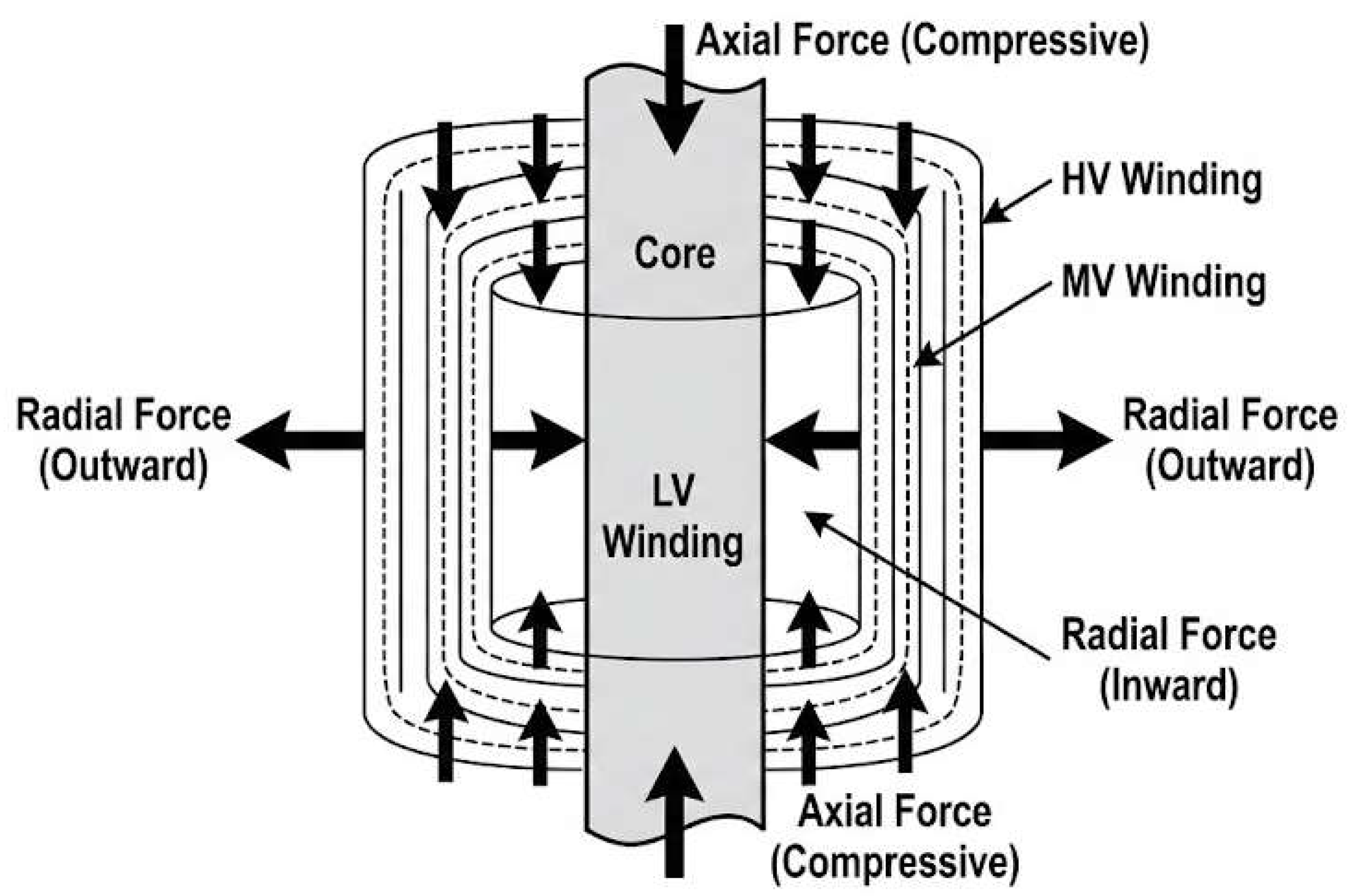
A transformer is essentially an electromagnetic energy conversion device. The excitation current in the energized winding establishes the main magnetic flux in the core; under fault conditions, the short-circuit currents also create leakage fields around the windings. Consequently, the windings are subjected to electromagnetic forces arising from the combined effects of the current and the magnetic field, as shown in
Figure 1. In this study, a coupled transient electromagnetic–mechanical analysis is performed; therefore, appropriate boundary conditions must be specified for both the electromagnetic field and the mechanical field.
The short-circuit electromagnetic forces acting on transformer windings primarily result from the interaction between the short-circuit current in the windings and the distribution of the leakage magnetic field in which they are located. Therefore, the magnetic-field distribution of the transformer must first be calculated. Based on Maxwell’s equations and the gauge condition
, the governing equation of the electromagnetic field [
28] can be derived as shown in Equation (1):
where
is the electrical conductivity;
is the permeability of vacuum;
is the relative permeability;
is the magnetic vector potential; and
is the winding current density.
For the short-circuit loading of a deformable (compressible) transformer winding, once the magnetic-field distribution is obtained, the effects of Ampère’s law, the gravity distribution, and the Lorentz force contribution should be considered in a coupled manner. Accordingly, the governing equation of the mechanical field [
29] can be derived as shown in Equation (2):
where
is the displacement vector;
is the material density;
is the limit vector;
denotes the nodal degrees of freedom;
is the strain; and
is the velocity field.
3. Study on Winding Force Based on 3D Simulation Model
In this study, COMSOL Multiphysics 6.1 software is used to establish a three-dimensional electromagnetic-structural coupling simulation model, with the following assumptions made during the simulation: the influences of excitation current and circulating current inside the transformer are not considered; the effect of hysteresis loss on the winding leakage magnetic field is ignored; the direct effects of press plates and pressure pins on the windings are neglected and replaced equivalently by applying preload force; and the effect of insulation paper structure between windings is omitted. Specifically, the magnetic field strength on the tank surface is set to 0, with the direction parallel to the tank surface. In addition, based on the specific parameters of the transformer, initial conditions such as the B-H characteristic curve of the iron core, winding turns, and current density are configured. For the structural field simulation, the solid mechanics physics module built into COMSOL is adopted, and Lorentz force is applied to the winding domain to simulate the process of windings subject to electrodynamic force under short-circuit conditions.
For the three-dimensional simulation model study, we established three simulation models: single-phase three-winding non-partitioned model, single-phase three-winding four-partitioned model, and single-phase three-winding four-partitioned refined (with spacers) model. We calculated the mechanical forces of each model under three types of symmetric short-circuit conditions (high-voltage side, medium-voltage side, and low-voltage side symmetric short circuits), with detailed simulation results presented as follows.
The non-partitioned model refers to a model where each winding is simplified as a single continuous solid cylinder. This model is mainly used for the macroscopic evaluation of the total electromagnetic force, as it neglects the longitudinal structural variations and local support constraints inside the windings. The four-partitioned model is an improved version of the non-partitioned model, which divides each winding domain into four discrete segments along the axial direction. It takes into account the non-uniform distribution of the leakage magnetic field along the winding height (especially near the ends), thus providing a more discrete stress profile than the solid cylinder approximation model. The four-partitioned refined (with spacers) model explicitly constructs the geometric entities of insulating spacers and stay bars. Unlike the previous two models that assume continuous mechanical constraints, this refined model simulates the discrete contact interfaces between conductors and support structures, and is able to capture the local stress concentration induced by the point support effect.
3.1. Three-Dimensional Single-Phase Three-Winding Model Without Zoning
In particular, the terms “high-voltage side (HV)/medium-voltage side (MV)/low-voltage side (LV)” used in this paper refer to the three sets of rated voltage windings of the transformer under study. The research object is a single-phase three-winding transformer, which consists of one HV winding and two low-voltage windings of different voltage classes (the MV winding and the LV winding) wound on the same iron core. The HV winding corresponds to the highest voltage class and is typically connected to the grid side, whereas the MV and LV windings correspond to two distinct low voltage classes and usually serve as the output sides for different voltage levels. The “HV/MV/LV side symmetrical short circuit” mentioned in this paper denotes that a short-circuit fault is applied at the terminals of the corresponding winding, with the remaining windings treated in accordance with the boundary conditions specified in this paper. Based on this setup, the electromagnetic forces on each winding and the structural responses induced by such forces are calculated separately.
To simulate the HV-side symmetrical short-circuit condition, an equivalent short-circuit loop is externally connected to the terminals of the HV winding under the electromagnetic field-circuit coupling framework in COMSOL to realize a three-phase symmetrical short circuit. Specifically, at the moment of fault application, the ends of the HV winding are connected to external circuit ports, and a short-circuit branch is configured in the external circuit. This creates a short-circuit boundary condition of approximately zero terminal voltage at the HV winding terminals, thereby forming a short-circuit current path and deriving the short-circuit current waveform via transient solution. The so-called “symmetrical short circuit” refers to a balanced fault where the three-phase currents have equal amplitudes and a mutual phase difference of 120°. In the single-phase equivalent model of this paper, the solution is performed using the per-phase equivalent representation of this balanced fault; thus, the obtained electromagnetic forces and structural responses correspond to the single-phase results under symmetrical short-circuit conditions. The implementation method for the MV/LV side symmetrical short circuit is consistent with the above: the short-circuit branch is only applied to the terminals of the corresponding winding, and the remaining windings are treated in accordance with the operating/boundary conditions specified in this paper.
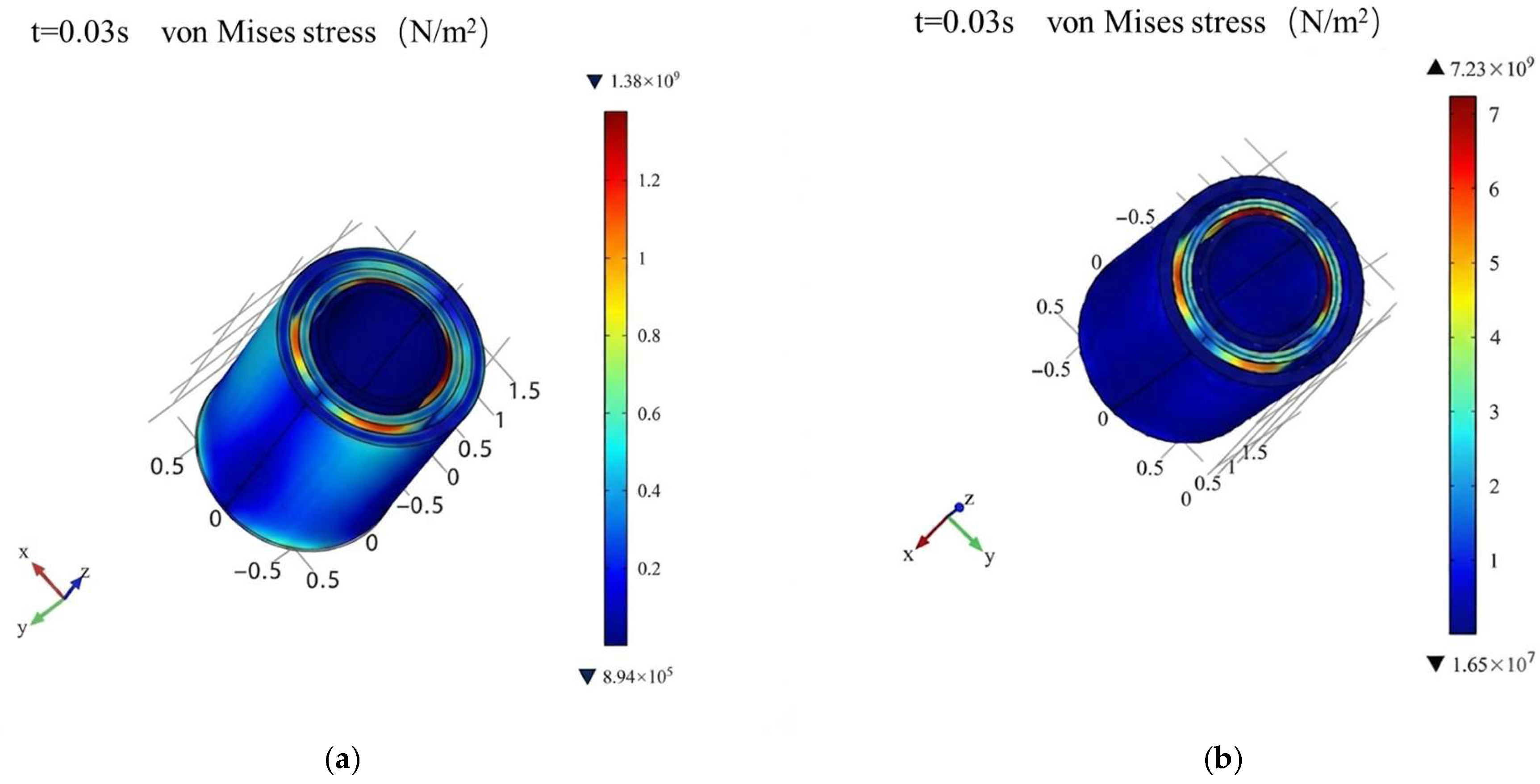
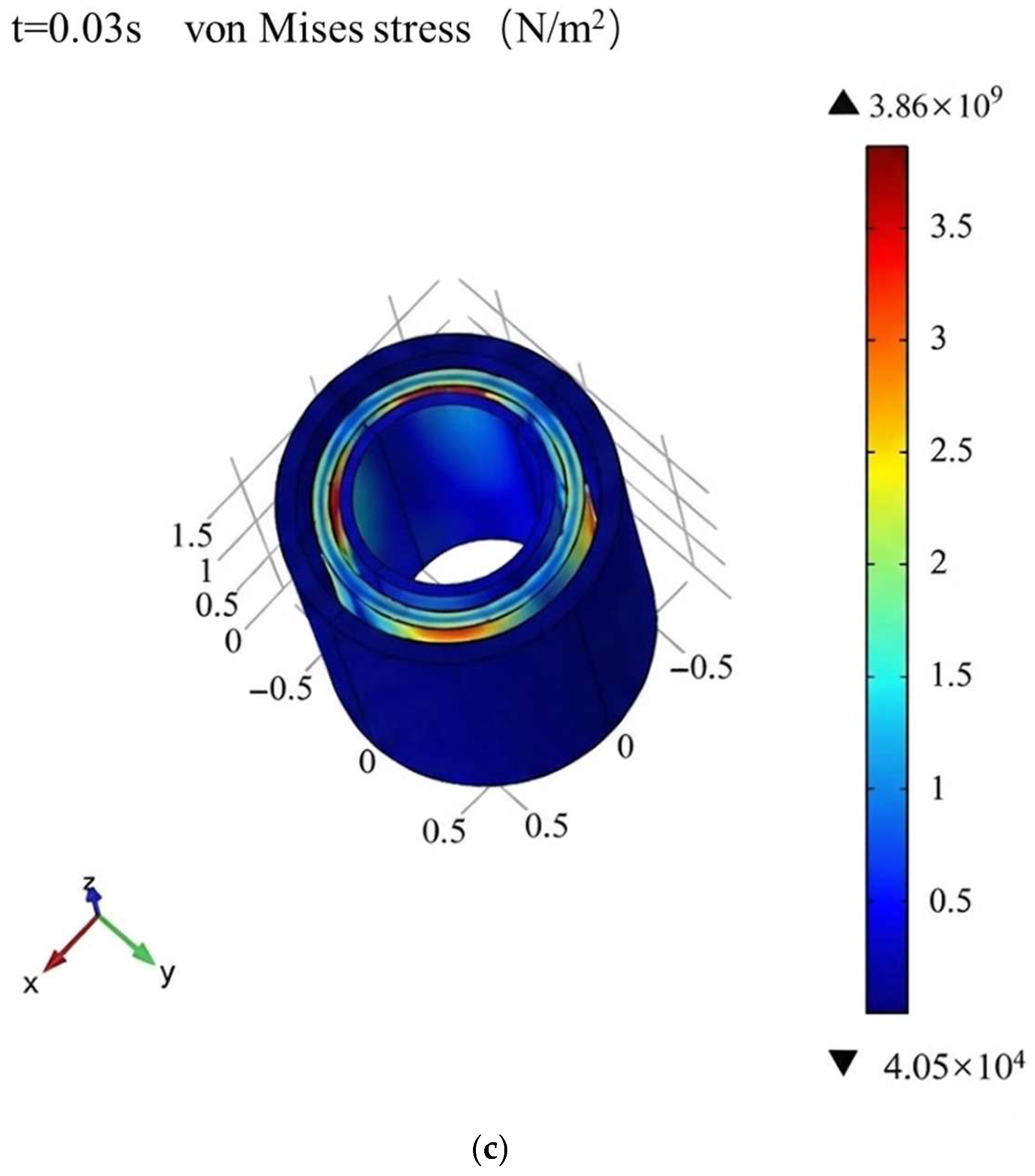
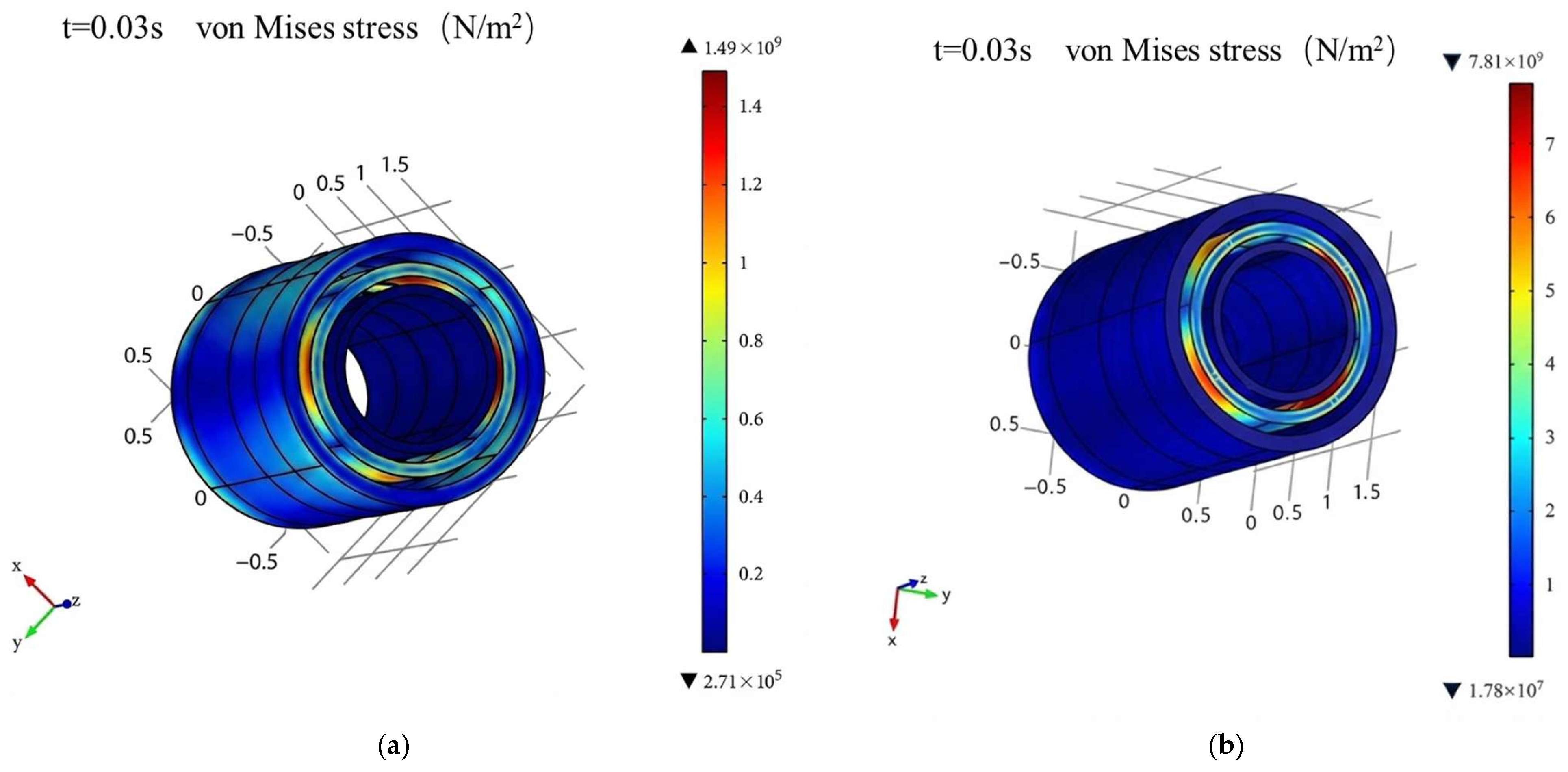
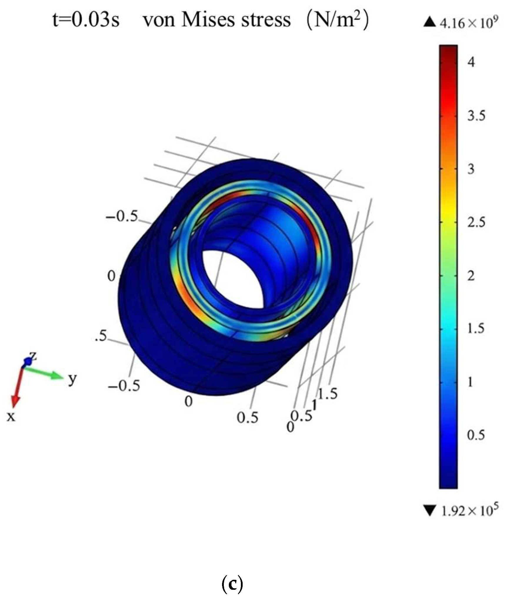
The contour plots of force distribution in each winding under different types of symmetrical short-circuit currents are shown in
Figure 2. As can be seen from
Figure 2, the medium-voltage winding experiences the largest overall force, followed by the high-voltage winding, while the low-voltage winding is subjected to the smallest force. Accordingly, the subsequent analysis focuses on the medium-voltage winding.
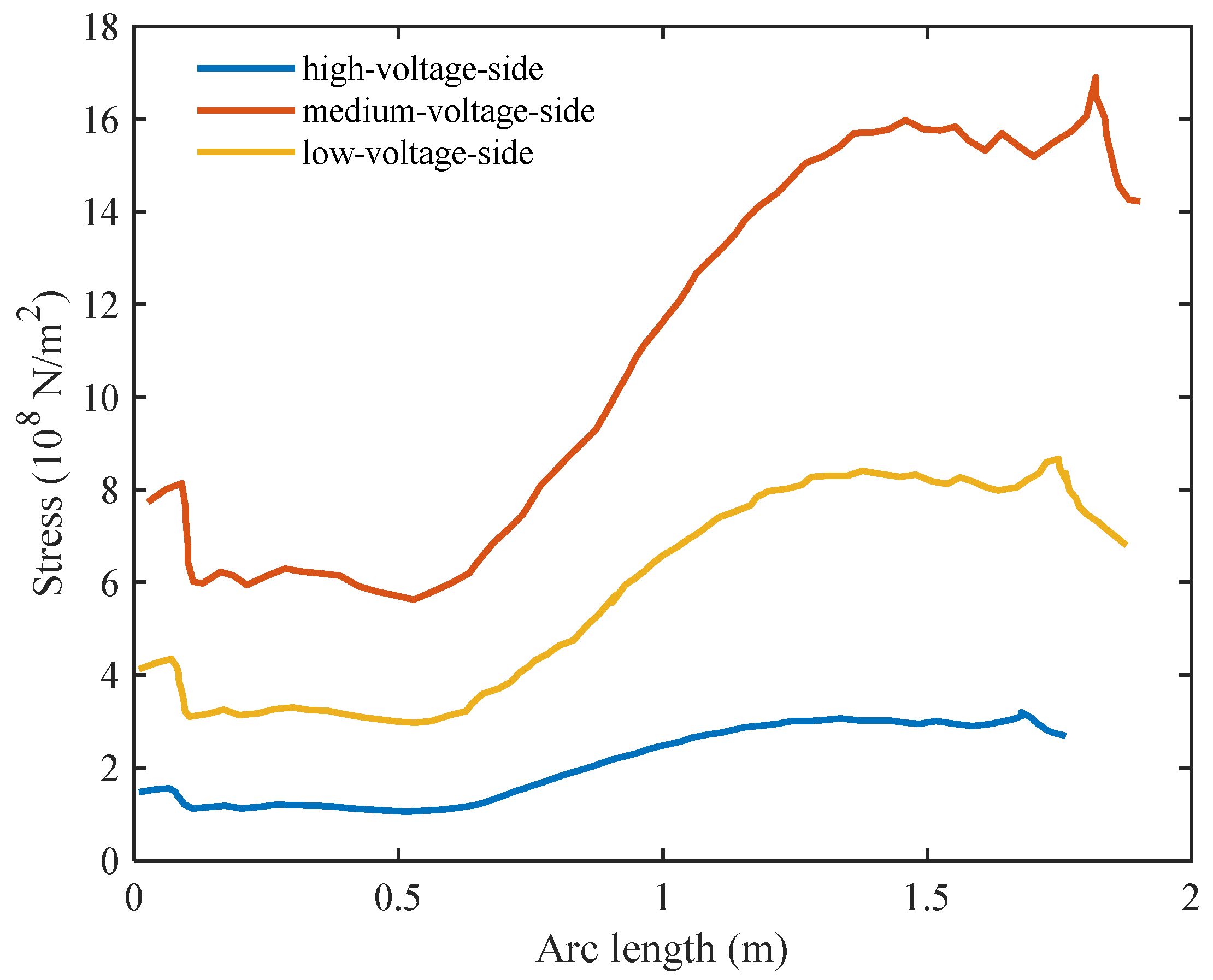
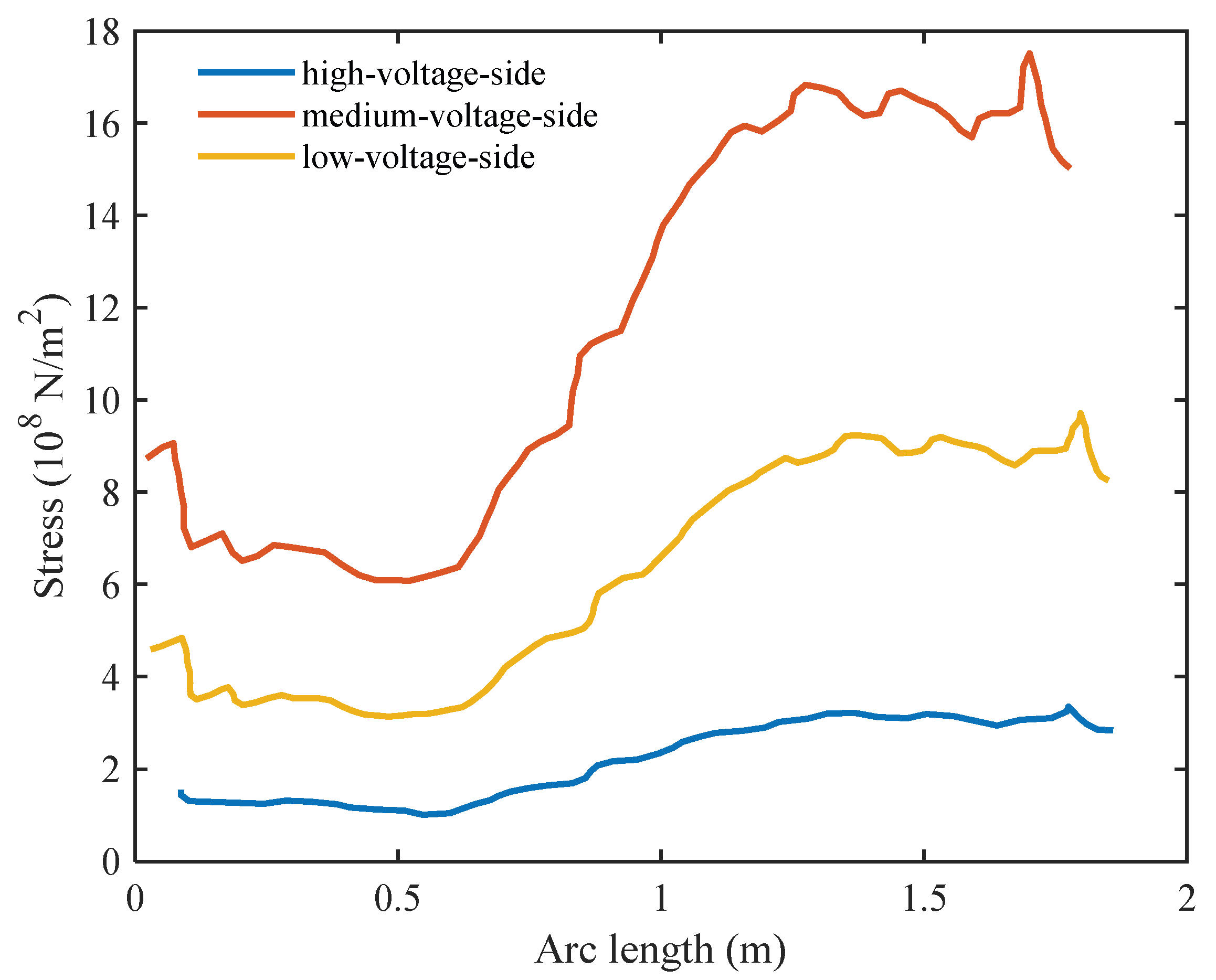
Local stress concentrations caused by boundary constraints at the winding ends were excluded. These boundary effects, attributed to the rigid clamping structure in the simulation model, do not represent the global stress state of the conductors. As shown in
Figure 3, after excluding the end distortions, the maximum force under the high-voltage-side symmetrical short-circuit occurs at the upper 3/10 of the medium-voltage winding, with a peak value of
N/m
2. Under the medium-voltage-side symmetrical short-circuit, the maximum occurs at approximately the upper 2/9 of the medium-voltage winding, reaching
N/m
2. Under the low-voltage-side symmetrical short-circuit, the maximum is also located at approximately the upper 2/9 of the medium-voltage winding, with a peak value of
N/m
2.
3.2. Three-Dimensional Single-Phase Three-Winding Four-Partitioned Model
The contour plots of force distribution in each winding under different types of symmetrical short-circuit currents are shown in
Figure 4. As indicated in
Figure 4, the medium-voltage winding experiences the largest overall force, followed by the high-voltage winding, while the low-voltage winding is subjected to the smallest force. Therefore, the subsequent analysis focuses on the medium-voltage winding.
As shown in
Figure 5, after excluding the end distortions, the maximum force under the high-voltage-side symmetrical short-circuit occurs at approximately the upper 3/10 of the medium-voltage winding, with a peak value of
N/m
2. Under the medium-voltage-side symmetrical short-circuit, the maximum force is also located at approximately the upper 3/10 of the medium-voltage winding, with a peak value of
N/m
2. Under the low-voltage-side symmetrical short-circuit, the maximum force likewise occurs at approximately the upper 3/10 of the medium-voltage winding, with a peak value of
N/m
2.
3.3. Three-Dimensional Single-Phase Three-Winding Four-Partitioned Refined Model
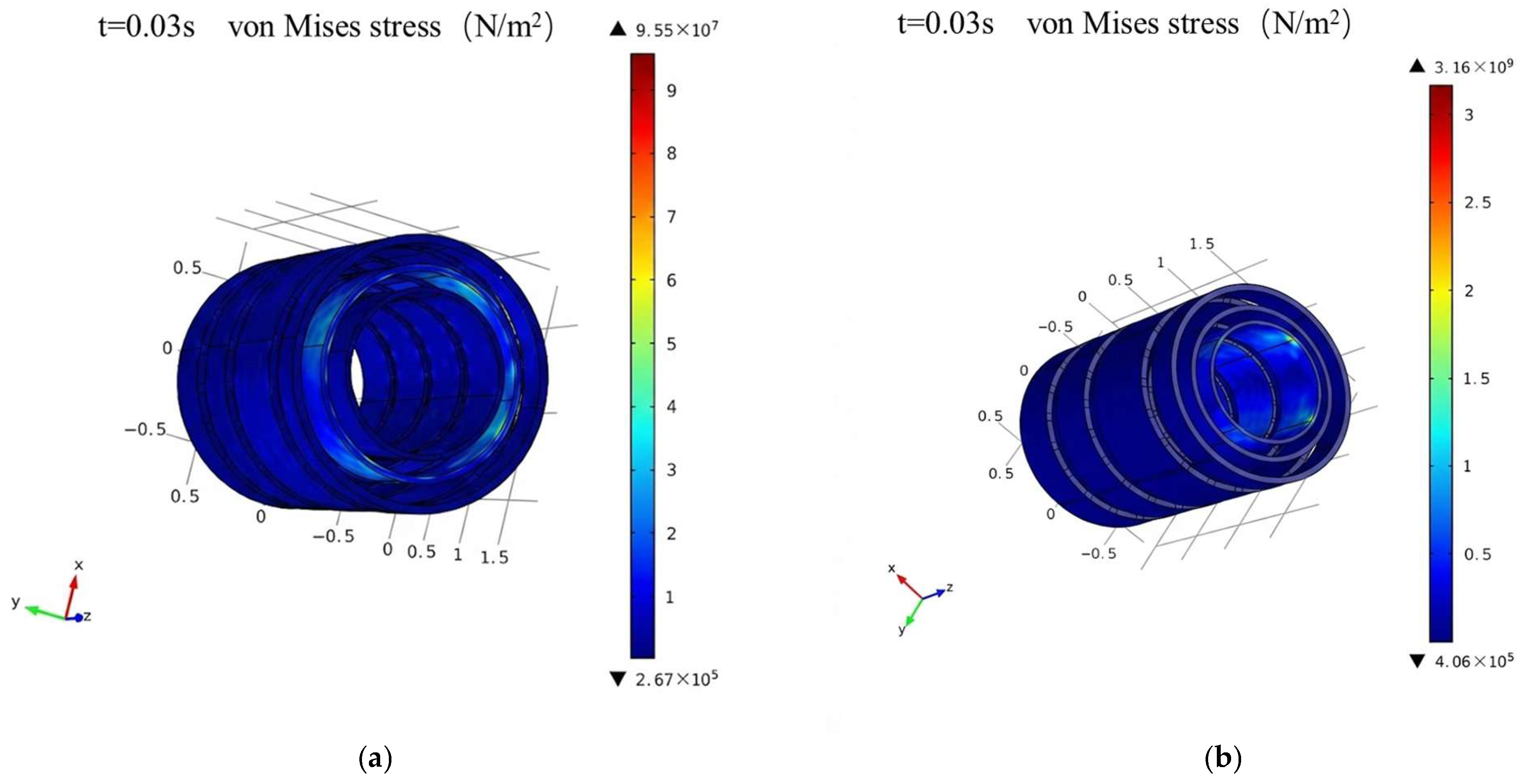
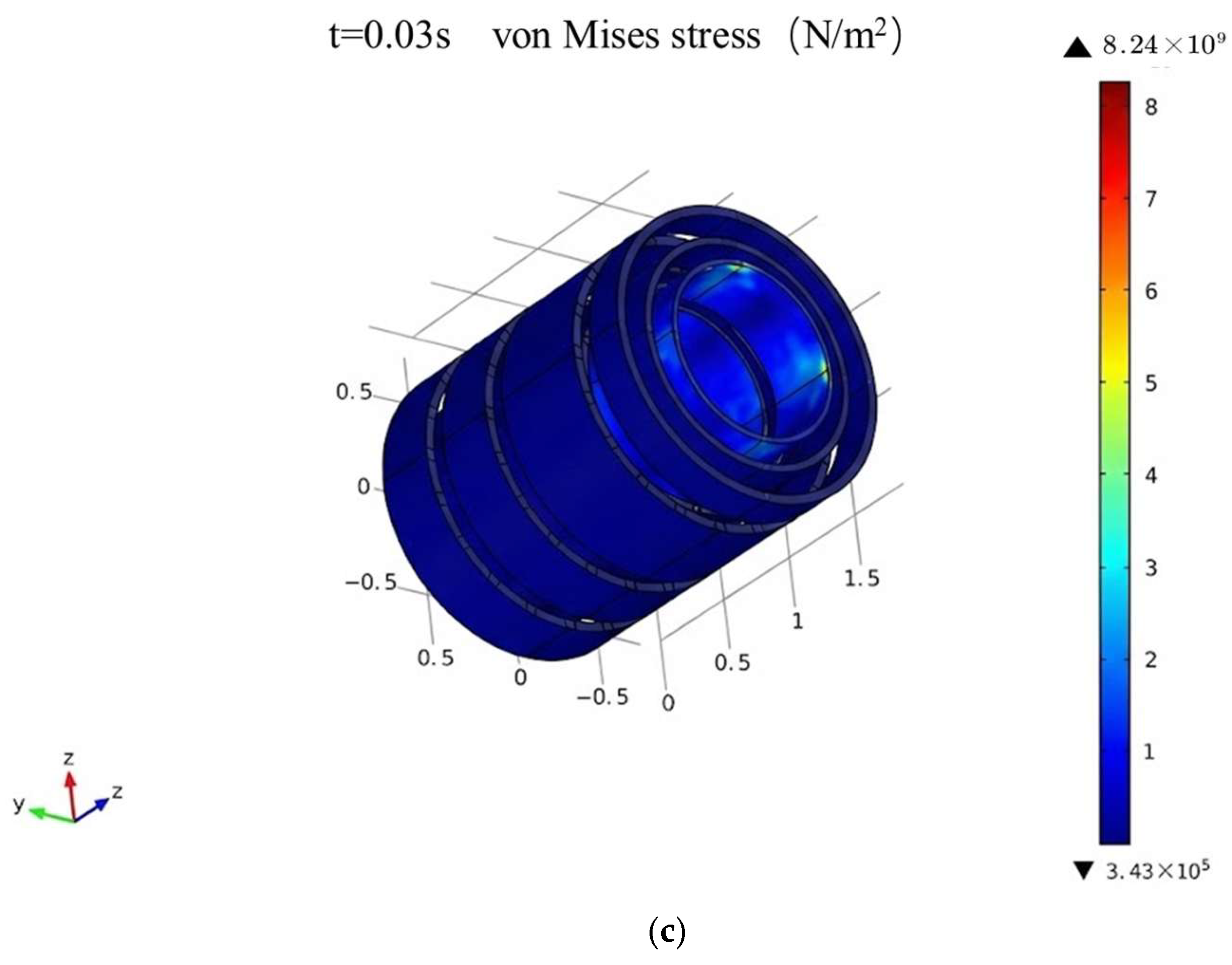
The contour plots of force distribution in each winding under different types of symmetrical short-circuit currents are shown in
Figure 6. As indicated in
Figure 6, under the high-voltage-side symmetrical short-circuit condition, the medium-voltage winding experiences the largest overall force, followed by the high-voltage winding, while the low-voltage winding is subjected to the smallest force. Under the medium-voltage-side and low-voltage-side symmetrical short-circuit conditions, the low-voltage winding exhibits the largest overall force, and the other two windings experience relatively smaller forces.
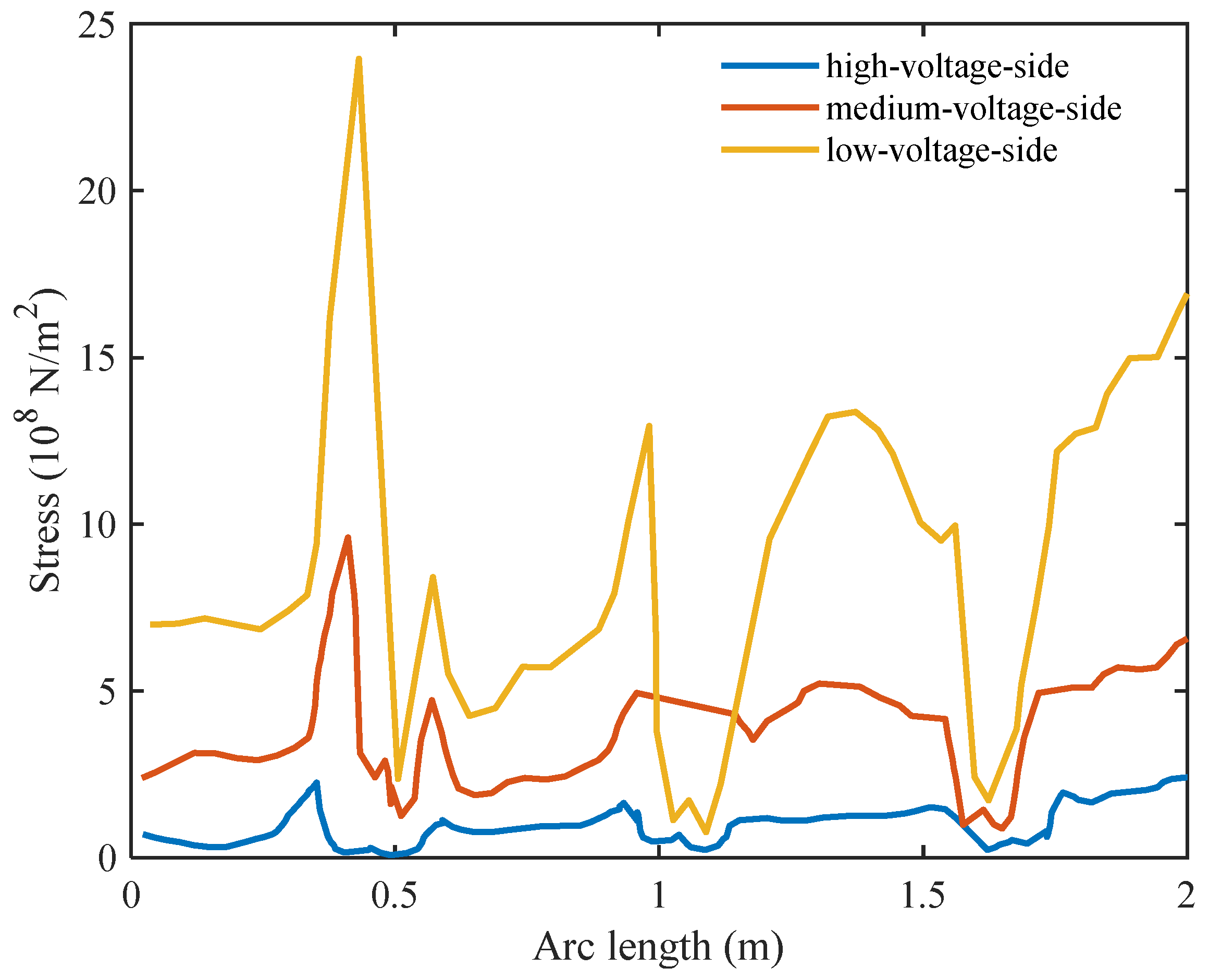
As shown in
Figure 7, after excluding the end distortions, the maximum force under the high-voltage-side symmetrical short-circuit occurs at approximately the lower 1/5 of the medium-voltage winding, with a peak value of
N/m
2. Under the medium-voltage-side symmetrical short-circuit, the maximum force is located at about the lower (2/9) of the low-voltage winding, with a peak value of
N/m
2. Under the low-voltage-side symmetrical short-circuit, the maximum force also occurs at approximately the lower (2/9) of the low-voltage winding, with a peak value of
N/m
2.
Based on the comparative analysis of the three simulation models under varying short-circuit conditions, as summarized in
Table 1, several key trends emerge. In the non-partitioned and basic four-partitioned models, the medium-voltage (MV) winding consistently exhibits the highest mechanical stress, with peak forces concentrated in the upper sections. However, the introduction of spacers in the refined four-partitioned model significantly alters this distribution. While the MV winding remains the most vulnerable under high-voltage side faults, the low-voltage (LV) winding becomes the critical component under medium- and low-voltage side short circuits, with the location of maximum force shifting to the lower sections. This shift underscores the critical role of detailed structural components like spacers in redistributing mechanical loads and highlights the necessity of using refined models to accurately identify vulnerable regions for effective transformer design and reinforcement.
4. Effects of Spacers and Clamping Blocks on Mechanically Weak Points of Winding Forces
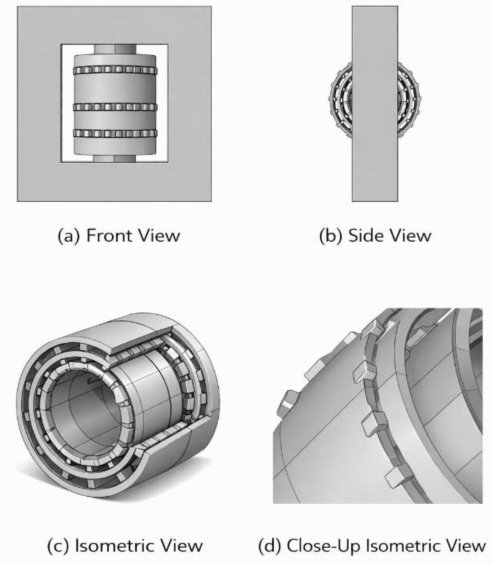
Based on the preceding results, it can be preliminarily concluded that the presence or absence of clamping blocks affects the magnitude of the mechanically weak points. To further investigate this effect in greater depth, a more detailed study was carried out. First, a three-dimensional simulation model incorporating spacers and clamping blocks was established. Then, the numbers of clamping blocks and spacers were varied to identify the corresponding trends, as shown in
Figure 8.
4.1. Effect of the Number of Spacers and Clamping Blocks
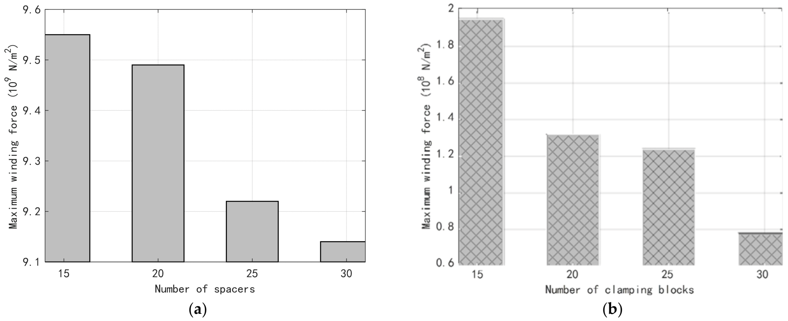
The numbers of inter-turn spacers and clamping blocks were set to 15, 20, 25, and 30, respectively, and simulations were performed under a medium-voltage-side symmetrical short-circuit current. The compiled results are shown in
Figure 9. As indicated in
Figure 9, with increasing numbers of spacers and clamping blocks, the peak force at the mechanically weak point of the transformer winding decreases gradually. Therefore, appropriately increasing the number of spacers can reduce the maximum force at the winding weak point and thereby improve transformer reliability.
4.2. Effect of Material Parameters of Spacers and Clamping Blocks
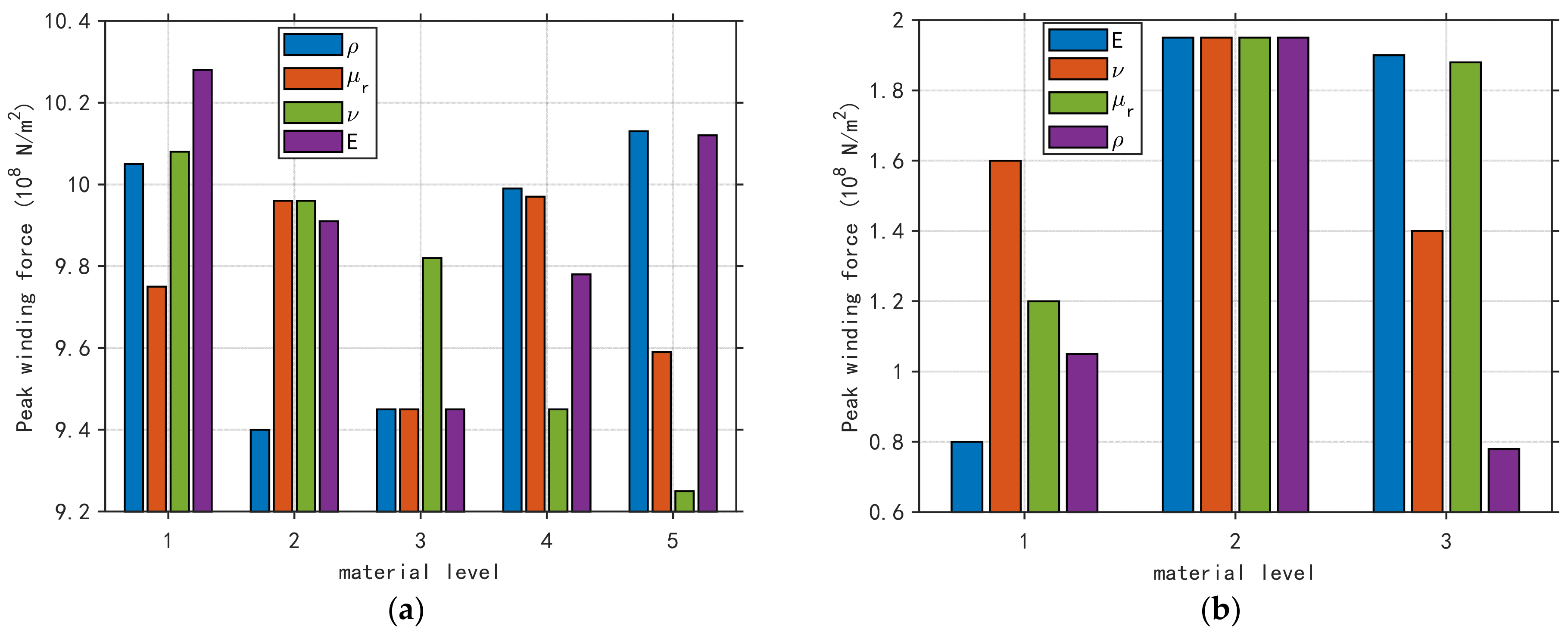
Practical transformer production experience indicates that the material parameters of each component may affect the distribution of winding force weak points. To investigate the influence law of material parameters on force weak points, this section separately analyzes the material parameters of stay bars and spacers, and clarifies their effect mechanism on force weak points through simulation calculations. For the study on the impact of stay bar material on weak points, this paper systematically sorts out the action law by comparing and analyzing each key influencing parameter. Both stay bars and spacers are made of high-density pressboard, which possesses excellent insulation performance and mechanical support characteristics, suitable for the internal working conditions of transformers.
As shown in
Figure 10, as the spacer density, relative permeability, and Young’s modulus vary, the maximum force at the mechanically weak point exhibits a minimum value. With an increase in the spacer Poisson’s ratio, the maximum force at the weak point decreases gradually. In contrast, for the clamping blocks, all four material parameters present a local maximum at the baseline (original) modeling point, indicating that the material properties adopted in the initial model lead to a relatively large peak force at the winding weak point. Therefore, from the perspective of mechanical loading, the originally selected material parameters are not optimal and should be re-optimized based on the simulation results. In addition, a horizontal comparison among the four material parameters of the clamping blocks indicates that Young’s modulus has the most significant influence, whereas the relative permeability has the least.
5. Influence of Short-Circuit Cumulative Effects on Winding Deformation
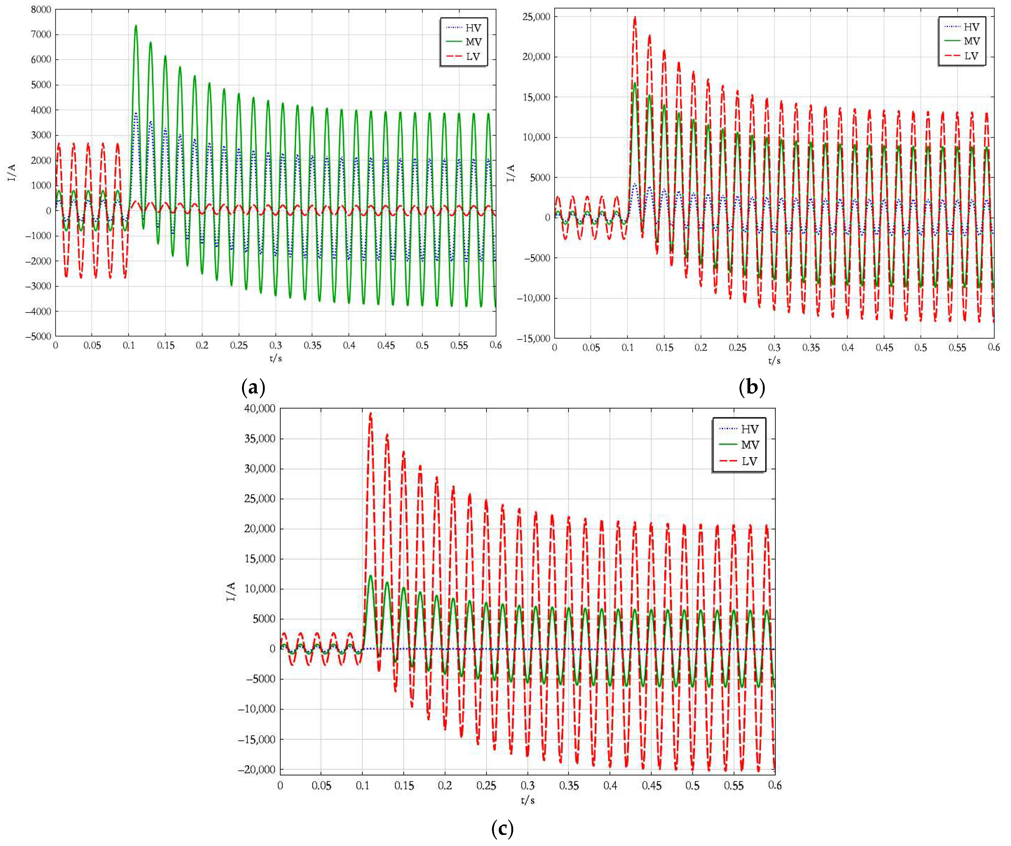
This section investigates the relationship between the number of short-circuit events and winding deformation under different short-circuit types. Based on the previously established three-dimensional simulation model, repeated winding short-circuit currents corresponding to different fault types were applied. Specifically, successive short-circuit current impulses were continuously imposed to simulate multiple short-circuit impacts. The interval between two adjacent impulses was set to 2 s, during which the transformer was assumed to operate at the rated current. The applied current load is shown in
Figure 11. It is assumed that different types of symmetrical short-circuits occur at the transformer terminal side at (t = 0.1) s. As shown in
Figure 11, the short-circuit current reaches a steady-state value after approximately 0.5 s.
When applying short-circuit current in the simulation, this paper sets the action time of each short-circuit current to 0.8 s, mainly based on the following three considerations: first, according to relevant standards, the automatic reclosing time of circuit breakers at transformer outlets is less than 1 s, i.e., the duration of short-circuit faults is less than 1 s; second, based on literature review and records of circuit breaker operating states during on-site transformer short-circuit accidents, short-circuit impacts trigger the operation of relay protection devices such as overcurrent protection, instantaneous trip protection, zero-sequence protection, and differential protection, among which overcurrent protection and zero-sequence protection operate significantly more frequently than others, with the time from fault occurrence to their operation usually being 2.2 s, while the corresponding instantaneous trip protection operates in 0.2 s and differential protection acts within 0.5 s; third, the short-circuit current consists of transient and steady-state components, where the transient component decays over time, and setting the short-circuit current action time to 0.8 s ensures that the current basically reaches a steady-state value, so the simulation results thus fully consider the effects of the entire short-circuit process.
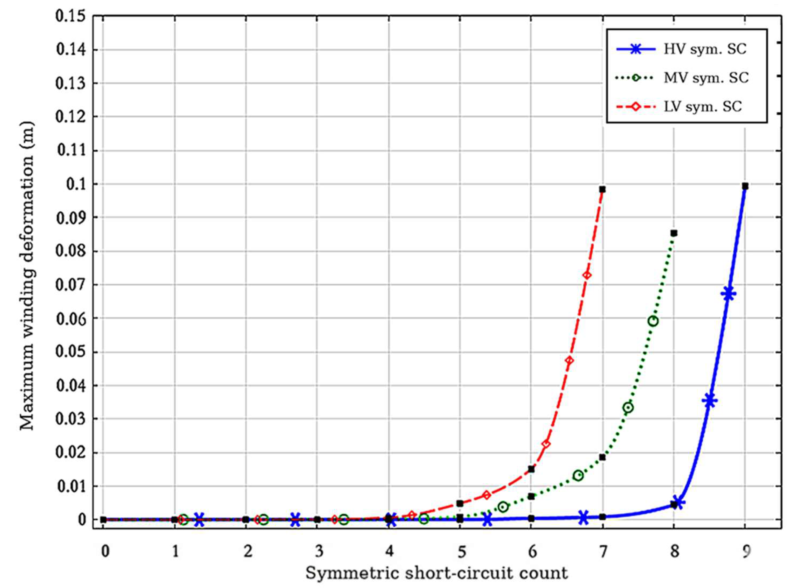
Furthermore, by applying multiple short-circuit currents to the winding model, the resulting winding deformation is obtained as shown in
Figure 12 It should be noted that the “zero-fault case (rated current only)” case refers to the maximum deformation under rated current only. At the instant when the rated current is applied, a slight deformation occurs in the transformer winding due to the current inrush effect.
As shown in the figure, for the same three-dimensional simulation model, the low-voltage-side symmetrical short-circuit has a more pronounced effect on winding deformation than the other two fault types. A critical point characterized by an abrupt displacement increase is reached after six low-voltage-side short-circuit current impulses, earlier than that for the high-voltage-side symmetrical short-circuit (eight impulses) and the medium-voltage-side symmetrical short-circuit (seven impulses).
6. Discussion
6.1. Core Findings
This study reveals the law governing the effect of model refinement on the identification of transformer short-circuit weak regions. In the traditional non-partitioned model, the medium-voltage (MV) winding is consistently identified as the component bearing the maximum force, with stress concentrated in its upper part. However, in the refined model incorporating spacers and stay bars, the point of maximum force shifts to the low-voltage (LV) winding during short circuits on the MV and LV sides, with the stress concentration position moving from the upper part to the lower part. This transfer indicates that the boundary constraints at the winding ends and discretely distributed support structures significantly alter the transmission path of electromagnetic forces. Neglecting these structural details will obscure local stress concentration phenomena, and traditional simplified models (e.g., the “solid” winding model) may mislead the reinforcement direction for short-circuit resistance design.
Furthermore, by simulating repeated short-circuit pulses, this study uncovers the nonlinear cumulative characteristics of winding deformation—that is, winding deformation does not increase at a constant rate but exhibits a distinct inflection point. A sudden surge in displacement occurs in the LV winding after the 6th short-circuit impact, which reflects that irreversible microplastic deformation leads to continuous loss of axial preload force. Additionally, the 6–8 short-circuit impact threshold identified in this study provides a quantitative foundation for transformer condition assessment and fault prediction. This means that even if a transformer is operating normally at present, mandatory internal inspection should be conducted once the number of short-circuit impacts approaches this threshold.
6.2. Innovative Contributions: Quantitative Optimization Basis for Support Structure Parameters
Different from previous studies that only focus on electromagnetic force calculation, this paper provides quantitative guidance for the mechanical reliability design of transformers through sensitivity analysis. The study finds that the stress suppression efficiency of increasing the number of press plates is much higher than that of increasing the number of spacers by the same proportion. This indicates that strengthening the end press plate structure is the primary means to improve the overall short-circuit resistance capacity in design optimization. What’s more, among all material parameters, the Young modulus of press plates exerts the most significant influence on the force amplitude. This corrects the non-optimal parameter settings adopted in the initial modeling and demonstrates the potential of systematic optimization of the mechanical properties of materials to extend winding service life.
In addition, this study translates the complex mechanical simulation results into actionable engineering guidelines, and innovatively proposes the “impact threshold” as a key indicator for transformer structural health monitoring. This provides a novel life prediction method for power grid operation and maintenance departments: by comparing the measured historical records of transformer outlet short circuits with the 6–8 instability threshold derived from this study, targeted preventive inspections can be implemented before the windings enter the accelerated failure stage.
6.3. Limitations and Future Work
Despite the progress made in refined modeling and cumulative effect analysis in this study, there are still the following limitations that need to be further addressed in future work:
Depth of Multiphysics Coupling: Although magneto-mechanical coupling is realized in the current simulation, the dynamic effect of temperature rise—induced by instantaneous high heat during short circuits—on the mechanical modulus of materials has not been fully considered. A real-time magneto-thermal–mechanical three-field coupling model should be introduced in future research.
Simplification of Complex Insulation Structures: The insulation paper structure between windings is simplified in the current model for the sake of computational efficiency. Subsequent research can adopt more refined meshing techniques to simulate the nonlinear compression characteristics of insulating layers under extreme pressure.
Scope of Experimental Verification: The current research mainly relies on numerical simulations based on physical parameters. Future work plans to carry out short-circuit destructive tests on scaled-down transformer models, acquire measured data through high-frequency optical fiber sensors (e.g., FBG), and further verify the accuracy of the cumulative deformation law.
7. Conclusions
This study establishes a refined three-dimensional magneto-mechanical coupling model to investigate the force distribution, parameter sensitivity, and cumulative deformation of windings in a 220 kV transformer. Specific conclusions drawn from the simulation results are as follows.
Transfer of Weak Regions: The introduction of detailed structural components significantly alters the stress distribution profile. In the simplified model, the medium-voltage (MV) winding is consistently the weakest, with stress concentrated in the upper region. However, in the refined model incorporating spacers, the mechanical weak point shifts to the low-voltage (LV) winding under short-circuit conditions on both the MV and LV sides. This confirms that simplified models may misjudge critical fault regions.
Sensitivity to Structural Parameters: Increasing the number of support structures can effectively alleviate local stress, but the mitigation effects vary significantly. Increasing the number of press plates by 2/3 reduces the maximum force by 36.55%, while increasing the number of spacers by the same ratio only reduces it by 3.46%, indicating that strengthening press plates is more critical for stress suppression. Regarding material properties, the Young modulus of press plates is the most significant factor affecting the force magnitude, and it is recommended to be the primary optimization variable in the design process.
Characteristics of Cumulative Deformation: Under repeated short-circuit impacts, winding deformation exhibits a nonlinear cumulative characteristic. Compared with other fault types, symmetric short circuits on the LV side result in the fastest deformation accumulation. A critical inflection point characterized by a sudden increase in displacement appears after the 6th impact for LV-side faults, which is earlier than the 7th or 8th impact for MV/high-voltage (HV) side faults. This threshold provides a quantitative theoretical basis for predicting the remaining structural life and implementing condition-based maintenance.
Author Contributions
Conceptualization, C.Z. and Y.L.; Methodology, C.Z., P.L. and F.J.; Software, C.Z. and P.L.; Validation, P.L., R.T., S.X. and F.J.; Formal analysis, C.Z., P.L., R.T., S.X. and F.J.; Investigation, P.L. and S.X.; Resources, S.X.; Data curation, R.T.; Writing—original draft, C.Z.; Writing—review & editing, P.L., R.T., Y.L., S.X. and F.J.; Visualization, C.Z. and R.T.; Supervision, Y.L. and F.J.; Project administration, Y.L.; Funding acquisition, Y.L. All authors have read and agreed to the published version of the manuscript.
Funding
This research was funded by the Chinese National Natural Science Foundation—Smart Grid Joint Fund (No. U2166213).
Data Availability Statement
The original contributions presented in this study are included in the article. Further inquiries can be directed to the corresponding author.
Conflicts of Interest
Authors Peng Li and Ruijuan Tan were employed by the company State Grid Corporation of China. The remaining authors declare that the research was conducted in the absence of any commercial or financial relationships that could be construed as a potential conflict of interest.
References
- Yang, W.; He, H.; Li, Z.; Yang, X. Simulation and Analysis of Short-Circuit Fault in DC Regional Power Grid with Energy Storage Systems. In Proceedings of the 5th International Conference on Mechanical, Electronics and Electrical and Automation Control, Chongqing, China, 9–11 May 2025; pp. 146–149. [Google Scholar]
- Wang, M.; Zhi, Q.; He, X.; Li, T.; Li, J. Real Time Fault Monitoring and Diagnosis Method for Power Grid Monitoring and Its Application. In Proceedings of the 2017 IEEE Conference on Energy Internet and Energy System Integration, Beijing, China, 26–28 November 2017; pp. 1–6. [Google Scholar]
- Zhang, L.; Li, S.; Xu, S.; Zhou, X.; Li, S.; Chen, Q.; Yang, J. A Data-Driven Intelligent Faults Identification Method for Power Grid Considering the Fault Characteristics of Inverter-Interfaced Renewable Energy Sources. In Proceedings of the 9th International Conference on Power Energy Systems and Applications, Nanjing, China, 20–22 June 2025; pp. 31–35. [Google Scholar]
- Wang, S.; Yang, F.; Wang, P.; Huang, Y.; Liu, F. Short-circuit Stress Analysis and Evaluation of 500 kV Transformer Windings. In Proceedings of the 10th International Conference on Power and Renewable Energy, Hangzhou, China, 19–22 September 2025; pp. 1593–1598. [Google Scholar]
- Luo, X.; Xiao, Q.; Wang, Q.; Gan, W.; Deng, B.; Sheng, Z. Research on Short-Circuit Force of Transformer Winding with Single-Phase Short-Circuit and Three-Phase Short-Circuit. In Proceedings of the 11th International Conference on Power and Energy Systems, Shanghai, China, 18–20 December 2021; pp. 219–223. [Google Scholar]
- Liu, Z. Manufacturing process improvement for short-circuit withstand capability of oil-immersed transformer windings. Today Manuf. Upgrade 2025, 11, 28–30. (In Chinese) [Google Scholar]
- GB/T 1094.5-2008; Power Transformers—Part 5: Ability to Withstand Short Circuit. Standards Press of China: Beijing, China, 2008.
- Ahn, H.-M.; Lee, J.-Y.; Kim, J.-K.; Oh, Y.-H.; Jung, S.-Y.; Hahn, S.-C. Finite-element analysis of short-circuit electromagnetic force in power transformer. IEEE Trans. Ind. Appl. 2011, 47, 1267–1272. [Google Scholar]
- Ahn, H.M.; Kim, S.Y.; Kim, J.K.; Oh, Y.H.; Hahn, S.C. Numerical investigation for transient electromagnetic force computation of power transformer during short-circuit condition. Int. J. Appl. Electromagn. Mech. 2016, 52, 1141–1149. [Google Scholar] [CrossRef]
- Ahn, H.-M.; Oh, Y.-H.; Kim, J.-K.; Song, J.-S.; Hahn, S.-C. Experimental Verification and Finite Element Analysis of Short-Circuit Electromagnetic Force for Dry-Type Transformer. IEEE Trans. Magn. 2012, 48, 819–822. [Google Scholar] [CrossRef]
- Yadav, S.; Suman, G.K.; Mehta, R.K. Study of Electromagnetic Forces on Windings of High Voltage Transformer during Short Circuit Fault. In Proceedings of the 3rd International Conference on Energy, Power and Environment: Towards Clean Energy Technologies, Shillong, India, 5–7 March 2021; pp. 1–5. [Google Scholar]
- Geißler, D.; Leibfried, T. Short-circuit strength of power transformer windings—Verification of tests by a finite element analysis-based model. IEEE Trans. Power Deliv. 2016, 32, 1705–1712. [Google Scholar]
- Sinha, A.; Kaur, S. Analysis of short circuit electromagnetic forces in transformer with asymmetrically placed windings using Finite Element Method. In Proceedings of the Second International Innovative Applications of Computational Intelligence on Power, Energy and Controls with Their Impact on Humanity, Ghaziabad, India, 18–19 November 2016; pp. 101–105. [Google Scholar]
- Andrade, A.F.; Costa, E.G.; Souza, J.P.C.; Andrade, F.L.; Araujo, J.F. Evaluation of computational models for electromagnetic force calculation in transformer windings using finite-element method. Int. J. Electr. Power Energy Syst. 2024, 156, 109744. [Google Scholar] [CrossRef]
- Yun, M.; Kim, C.; Choi, M.; Kim, Y. A Study on Structural Safety Evaluation Technology for Lead Support Structure in Transformer with Considerations on Short-Circuit Failure. In Proceedings of the ASME 2014 International Mechanical Engineering Congress and Exposition, Montreal, QC, Canada, 14–20 November 2014. Paper No. IMECE2014-39053; V009T12A095. [Google Scholar]
- Wang, J.; He, J.; Chen, X.; Tian, T.; Yao, C.; Abu-Siada, A. Power transformer short-circuit force calculation using three and two-dimensional finite-element analysis. Energies 2025, 18, 3898. [Google Scholar] [CrossRef]
- Zou, D.; Zheng, Y.; Qian, G.; Yan, B.; Peng, Q.; Wang, S. Study on axial force distribution characteristics and test analysis of transformers under short circuit. Transformer 2020, 57, 24–28. (In Chinese) [Google Scholar]
- Dawood, K.; Kırış, G.K. Assessment of Electromagnetic Forces in Transformers Under Open-Circuit and Short-Circuit Conditions. In Proceedings of the 7th International Congress on Human-Computer Interaction, Optimization and Robotic Applications, Ankara, Turkiye, 23–24 May 2025; pp. 1–5. [Google Scholar]
- Xu, Z.; Li, P.; Li, L.; Sui, H.; Wang, R.; Zhao, Z.; Zhang, S.; Wang, K. Cumulative effect of laminated spacers for transformers based on equivalent short-circuit tests. Proc. CSEE 2024, 44, 4535–4544. (In Chinese) [Google Scholar]
- Yang, F.; Gao, S.; Zhao, Y.; Wang, J.; Wang, P. Analysis of transformer winding short-circuit force and deformation based on magnetic field gradient tensor. Trans. China Electrotech. Soc. 2026, 41, 14–25. (In Chinese) [Google Scholar]
- Miao, Y. Radial Stability of Power Transformer Windings Considering Cumulative Effects. Master’s Thesis, Shenyang University of Technology, Shenyang, China, 2024. (In Chinese) [Google Scholar]
- Wang, S.; Zhang, H.; Wang, S.; Li, H.; Yuan, D. Cumulative deformation analysis for transformer winding under short-circuit fault using magnetic–structural coupling model. IEEE Trans. Appl. Supercond. 2016, 26, 0606605. [Google Scholar] [CrossRef]
- Zhang, H.J.; Wang, S.H.; Wang, S. Cumulative deformation analysis of transformer winding under short-circuit fault using 3-D FEM. In Proceedings of the IEEE International Conference on Applied Superconductivity and Electromagnetic Devices, Shanghai, China, 20–23 November 2015; pp. 370–371. [Google Scholar]
- Yao, S.; Hao, Z.; Si, J.; Zhang, Y. Dynamic deformation analysis of power transformer windings under multiple short-circuit impacts. In Proceedings of the 2019 IEEE 8th International Conference on Advanced Power System Automation and Protection, Xi’an, China, 21–24 October 2019; pp. 1394–1397. [Google Scholar]
- Lin, X.; Liu, J.; Wang, F.; Ai, W.; Li, Z.; Chen, S. Magnetic-structural coupled simulation of power transformer winding cumulative effect. In Proceedings of the 2022 IEEE 5th International Electrical and Energy Conference, Nanjing, China, 27–29 May 2022; pp. 2860–2865. [Google Scholar]
- Guo, H.; Li, X.; Liu, J.; Chen, S.; Zhu, D.; Wang, F.; Li, L.; Li, Z.; Li, J. Experimental study on the cumulative deformation effects of power transformer windings using fiber Bragg grating sensors. IEEE Trans. Instrum. Meas. 2025, 74, 1–12. [Google Scholar] [CrossRef]
- Liu, J.; Li, K.; Chen, P.; Xu, K.; Zhuo, R.; Gao, M.; Ai, W.; Guo, H.; Chen, S. Simulation study of transformer cumulative effect under different short-circuit current shocks and prestressing effects. In Proceedings of the 2025 IEEE 8th International Electrical and Energy Conference, Changsha, China, 16–18 May 2025; pp. 1548–1553. [Google Scholar]
- Bai, Z. Fatigue and Lifetime of Transformer Windings under Cumulative Mixed Short-Circuit Forces. Ph.D. Thesis, Shenyang University of Technology, Shenyang, China, 2025. (In Chinese) [Google Scholar]
- Yu, X. Short-Circuit Vibration Characteristics of Power Transformer Windings and Influencing Factors. Master’s Thesis, Shenyang University of Technology, Shenyang, China, 2025. (In Chinese) [Google Scholar]
Figure 1.
Schematic diagram of winding forces.
Figure 1.
Schematic diagram of winding forces.
Figure 2.
Contour plot of the stress distribution for the single-phase three-winding non-partitioned model. (a) high-voltage-side symmetrical short-circuit, (b) medium-voltage-side symmetrical short-circuit, (c) low-voltage-side symmetrical short-circuit.
Figure 2.
Contour plot of the stress distribution for the single-phase three-winding non-partitioned model. (a) high-voltage-side symmetrical short-circuit, (b) medium-voltage-side symmetrical short-circuit, (c) low-voltage-side symmetrical short-circuit.
Figure 3.
Force distribution of the weakest winding in the single-phase three-winding non-partitioned model.
Figure 3.
Force distribution of the weakest winding in the single-phase three-winding non-partitioned model.
Figure 4.
Contour plot of the stress distribution for the single-phase three-winding four-partitioned model. (a) high-voltage-side symmetrical short-circuit, (b) medium-voltage-side symmetrical short-circuit, (c) low-voltage-side symmetrical short-circuit.
Figure 4.
Contour plot of the stress distribution for the single-phase three-winding four-partitioned model. (a) high-voltage-side symmetrical short-circuit, (b) medium-voltage-side symmetrical short-circuit, (c) low-voltage-side symmetrical short-circuit.
Figure 5.
Force distribution of the weakest winding in the single-phase three-winding four-partitioned model.
Figure 5.
Force distribution of the weakest winding in the single-phase three-winding four-partitioned model.
Figure 6.
Contour plot of the stress distribution for the single-phase three-winding four-partitioned refined (with spacers) model. (a) high-voltage-side symmetrical short-circuit, (b) medium-voltage-side symmetrical short-circuit, (c) low-voltage-side symmetrical short-circuit.
Figure 6.
Contour plot of the stress distribution for the single-phase three-winding four-partitioned refined (with spacers) model. (a) high-voltage-side symmetrical short-circuit, (b) medium-voltage-side symmetrical short-circuit, (c) low-voltage-side symmetrical short-circuit.
Figure 7.
Force distribution of the weakest winding in the single-phase three-winding four-partitioned refined (with spacers) model.
Figure 7.
Force distribution of the weakest winding in the single-phase three-winding four-partitioned refined (with spacers) model.
Figure 8.
Finite-element models of the spacers and clamping blocks.
Figure 8.
Finite-element models of the spacers and clamping blocks.
Figure 9.
Relationships between the numbers of spacers/clamping blocks and the mechanically weak point. (a) Effect of spacer number on the weak point, (b) effect of clamping block number on the weak point.
Figure 9.
Relationships between the numbers of spacers/clamping blocks and the mechanically weak point. (a) Effect of spacer number on the weak point, (b) effect of clamping block number on the weak point.
Figure 10.
Relationships between the material parameters of spacers/clamping blocks and the mechanically weak point. (a) Effect of spacer material parameters on the weak point, (b) effect of clamping block material parameters on the weak point.
Figure 10.
Relationships between the material parameters of spacers/clamping blocks and the mechanically weak point. (a) Effect of spacer material parameters on the weak point, (b) effect of clamping block material parameters on the weak point.
Figure 11.
Schematic current waveforms under different short-circuit types at (t = 0.1) s. (a) high-voltage-side symmetrical short-circuit current waveform, (b) medium-voltage-side symmetrical short-circuit current waveform, (c) low-voltage-side symmetrical short-circuit current waveform.
Figure 11.
Schematic current waveforms under different short-circuit types at (t = 0.1) s. (a) high-voltage-side symmetrical short-circuit current waveform, (b) medium-voltage-side symmetrical short-circuit current waveform, (c) low-voltage-side symmetrical short-circuit current waveform.
Figure 12.
Relationship between the number of symmetrical short-circuit events and the maximum winding deformation.
Figure 12.
Relationship between the number of symmetrical short-circuit events and the maximum winding deformation.
Table 1.
Summary of Maximum Mechanical Forces and Vulnerable Locations Under Different Simulation Models and Short-Circuit Conditions.
Table 1.
Summary of Maximum Mechanical Forces and Vulnerable Locations Under Different Simulation Models and Short-Circuit Conditions.
| Simulation Model | Short-Circuit Condition | Weakest Winding | Location of Maximum Force | Peak Force Value (N/m2) |
|---|
| Non-partitioned | HV-side symmetrical | MV Winding | Upper 3/10 | |
| MV-side symmetrical | MV Winding | Upper 2/9 | |
| LV-side symmetrical | MV Winding | Upper 2/9 | |
| Four-partitioned | HV-side symmetrical | MV Winding | Upper 3/10 | |
| MV-side symmetrical | MV Winding | Upper 3/10 | |
| LV-side symmetrical | MV Winding | Upper 3/10 | |
| Four-partitioned (with spacers) | HV-side symmetrical | MV Winding | Lower 1/5 | |
| MV-side symmetrical | LV Winding | Lower 2/9 | |
| LV-side symmetrical | LV Winding | Lower 2/9 | |
| Disclaimer/Publisher’s Note: The statements, opinions and data contained in all publications are solely those of the individual author(s) and contributor(s) and not of MDPI and/or the editor(s). MDPI and/or the editor(s) disclaim responsibility for any injury to people or property resulting from any ideas, methods, instructions or products referred to in the content. |