1. Introduction
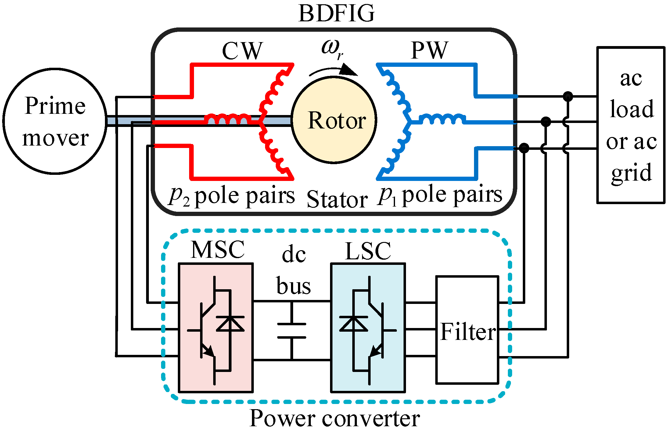
In recent years, brushless doubly-fed induction generators (BDFIGs) have received more and more attention and development [
1,
2,
3]. The BDFIG is equipped with two stator winding sets featuring distinct pole pairs, along with a specially designed rotor. The first winding, designated as the power winding (PW), serves as the main stator winding. The second winding, referred to as the control winding (CW), is utilized for control purposes [
4,
5]. These two stator windings are not directly linked but are instead coupled indirectly through the rotor windings. Compared with the traditional doubly-fed induction generator (DFIG), the special structure of the BDFIG eliminates the brushes and slip rings, thus greatly improving the stability and reducing the maintenance cost, which also makes the brushless doubly-fed motor more promising [
6,
7].
At present, the BDFIG can be employed at both grid-connected and standalone power generation modes in microgrids [
8,
9]. The grid-connected power generation system regulates the active and reactive power of the BDFIG [
10], while the standalone power generation system needs to maintain the amplitude and frequency of the PW voltage constant [
11]. Compared to the grid-connected BDFIG, the output voltage of the standalone BDFIG in microgrid is more susceptible to load disturbances, which places higher requirements on the stability control of the output voltage [
12,
13].
Some control methods have been proposed for BDFIG. The amplitude and frequency control method has been studied in [
14,
15], in which the amplitude and frequency of PW voltage are controlled by the amplitude and frequency of CW current. This method is simple and easy to implement, but its response is slow and cannot control the phase of the PW voltage. A vector control method based on the orientation of the PW voltage is mentioned in [
16], which combines the relationship between the
d- and
q-axis PW voltages and the
d- and
q-axis CW currents, thereby controlling the amplitude and phase of the PW voltage. An improved sensorless control strategy was proposed in [
17], which enables smooth and stable regulation of both active and reactive power, even under severe grid voltage fluctuations and parameter mismatches. Ref. [
18] examines the low-voltage ride-through (LVRT) control of the BDFIG’s MSC and reveals that the BDFIG exhibits enhanced LVRT capability compared to the traditional DFIG. With the aim of enhancing the AC voltage control performance of DFIG in wind power systems, the study in [
19] investigates an artificial neural network (ANN)-based control strategy, demonstrating its superiority over conventional proportional-integral (PI) controllers in both response time and stability.
In the standalone BDFIG power generation system, the PW voltage amplitude is one of the main control targets, which is susceptible to load disturbances. Some control methods have been proposed to address this issue. A vector control method utilizing CW current orientation is presented in [
20], which accelerates the response of the CW current control loop through decoupling and feedforward compensation. However, this control method just only improves the CW current control loop, and does not significantly enhance the PW voltage quality under heavy load disturbance due to the limited machine side converter (MSC) capacity. In Ref. [
21], a feedforward compensation method by means of PW flux orientation is mentioned. This method uses the
d- and
q-axis PW currents to calculate the feedforward compensation current of the
d- and
q-axis CW currents, thereby improving the system response speed and strengthening anti-load disturbance ability. This method not only requires a large number of machine parameters, but also cannot provide good results when the MSC capacity is insufficient. For the suppression of load disturbance by line side converter (LSC), a method is introduced in grid-connected power generation system. In the grid-connected system, when the grid voltage drops, the LSC transmits reactive current to the grid to improve the grid voltage [
22]. For the standalone power generation system, when the PW voltage drops due to the inductive load, the LSC can deliver reactive current to the load to suppress the PW voltage fluctuation. In Ref. [
23], the LSC is employed to supply the reactive power to the PW for improving the PW voltage stability. This control method needs no machine parameters and has good response speed, but the effect is unsatisfactory when the power factor of the load is high or the capacity of the LSC is not enough.
All of the control methods mentioned above only use the single power converter (i.e., MSC or LSC) as a means to suppress load disturbances, and do not make full use of the capacity of the dual power converters in the control system. In order to address this issue, this paper develops a new coordinated control method for the standalone BDFIG, which can make full use of the redundant capacity of MSC and LSC to significantly reduce the PW voltage amplitude fluctuation and shorten transient response time.
3. Performance Analysis of the Traditional Control Scheme Under Load Disturbance
In the traditional control scheme for the standalone BDFIG system, the MSC can be regarded as an individual voltage source to regulate the air-gap flux. And the LSC can output power to loads or absorb power from PW for maintaining the dc bus voltage constant. In steady state, the LSC together with the filter can be seen as connected to a constant voltage source. Under this condition, the combination of the LSC and the filter can be regarded as a current source, which can output current to loads at the super-synchronous rotor speed and also can absorb current from PW at the sub-synchronous rotor speed.
According to the derivation in
Section 1, the PW and CW voltages in steady state can be expressed as
Since the positive direction of the PW current is based on the motor convention in the dynamic mathematical model of BDFIG shown in Equations (3)–(8), it is necessary to set
to analyze the performance of the BDFIG under the generation mode. Hence, the PW voltage described in Equation (9) can be rewritten as
where
is defined as the electromotive force (EMF) in the PW, which is induced by the CW current, and
.
Similarly, the CW voltage in Equation (10) can be rewritten as
where
is defined as the EMF in the PW, which is induced by the PW current, and
.
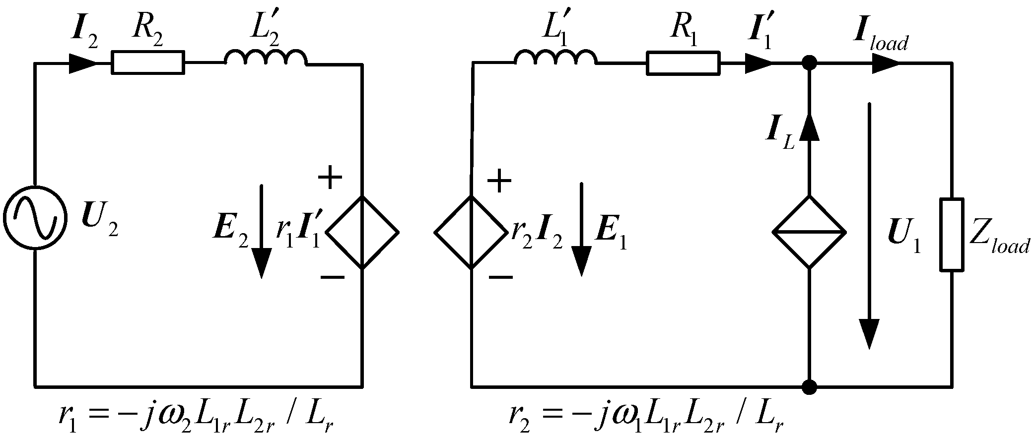
Based on the above analysis and Equations (11) and (12), the simplified equivalent circuit of the standalone BDFIG system can be illustrated in
Figure 2.
When the load is changed and the CW current is not adjusted in time, the
E1 induced by the CW current can be regarded as unchanged. Consequently, the variation in the PW voltage can be expressed as
where
and
represent the variation in the PW voltage and PW current vectors, respectively.
In general, the value of
R1 is much smaller than that of
, and the expression of the PW voltage variation can be simplified as
Given that the initial phase angle of the PW voltage is zero, the PW current
can be expressed as
where
and
indicate the active and reactive currents of PW, respectively.
Substituting Equation (15) with (14), the PW voltage variation can be given by
In the traditional control scheme, the LSC operates in the unit power factor, which means that the PW must therefore supply the entirety of the load’s reactive current. Equation (16) indicates that a substantial variation in the PW reactive current due to load changes can result in considerable PW voltage fluctuations. This effect is particularly pronounced during the direct start-up of induction motors. In addition, variations in the PW active current also contribute to significant voltage fluctuations at sub-synchronous rotor speeds. This occurs because, within this speed range, the PW must supply both the total active load current and the active current for the LSC.
4. Design of Control Scheme
To address the significant PW voltage fluctuations induced by load disturbances, a control scheme utilizing dual-converter compensation is derived in this section.
4.1. Basic PW Voltage Control Loop
The
d- and
q-axis component expressions of Equations (7) and (8) can be written as
where
ψrd and
ψrq represent rotor flux
d- and
q-axis components,
ird and
irq rotor current
d- and
q-axis components,
i1d and
i1q PW current
d- and
q-axis components,
i2d and
i2q CW current
d- and
q-axis components.
Substituting Equation (18) with (17), the
d- and
q-axis rotor currents can be expressed as
where
.
The zeros and poles of the expressions of the variable
M are very close. Hence, the variable
M can be approximated to 1. Consequently, the
d- and
q-axis rotor currents can be simplified as
The
d- and
q-axis component expressions of Equations (3) and (4) can be written as
where
u1d and
u1q represent PW voltage
d- and
q-axis components,
ψ1d and
ψ1q indicate PW flux
d- and
q-axis components.
At an equilibrium point under steady-state conditions, the PW flux can be regarded as the constant quantity. Hence, Equation (21) can be simplified as
Substituting Equations (20) and (22) with Equation (23), the
d- and
q-axis PW voltages can be rewritten as
In Equation (24), the first two terms of the expressions of
u1d and
u1q are related to the PW current. Since the PW current is affected by the load and the rotor speed, the first two terms of each expression in Equation (24) are disturbance terms. Hence, Equation (24) can be rewritten as
where
Kd and Kq indicate the linear relationship between the PW voltage and CW current. Dd and Dq represent the disturbance terms caused by the load and the rotor speed.
From Equation (25), ignoring the disturbance terms
Dd and
Dq, it can be noted that the voltages
u1d and
u1q exhibit linear dependence on the currents
i2q and
i2d, respectively. This linear relationship allows
u1d and
u1q to be regulated via
i2q and
i2d, respectively, using two PI controllers. The output of the two PI controllers can serve as the reference values of the CW currents
i2q and
i2d. In addition, the terms
Dd +
Kdi2q and
Dq −
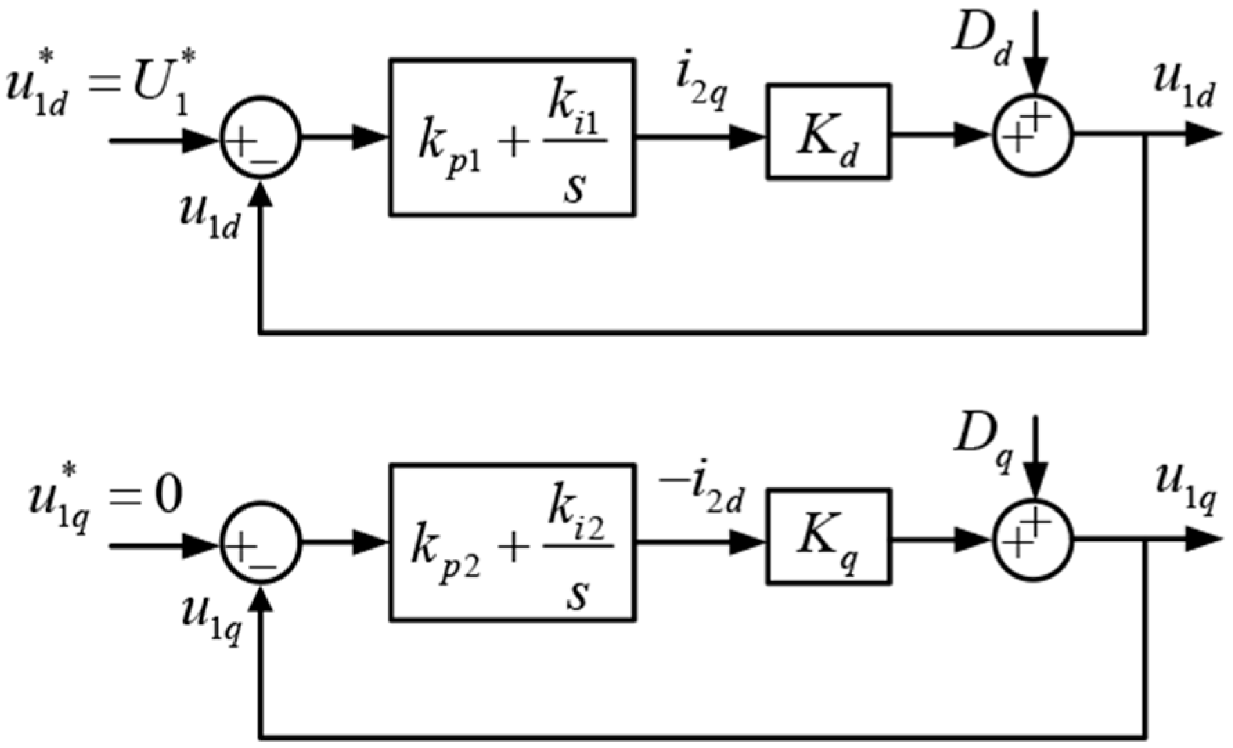
Kqi2d can be regarded as the controlled plants. Based on the above analysis, the basic PW voltage control loop can be presented in
Figure 3.
4.2. Load Disturbance Suppression Based on MSC
According to Kirchhoff’s current law, the currents of the PW, load, and LSC are related, and the relationship can be described as follows:
where
isd and
isq are the
d- and
q-axis components of LSC current, and
ild and
ilq are the
d- and
q-axis components of load current.
The CW power passes through MSC and is eventually delivered to the load by LSC. In practical applications, the BDFIG mainly works near the natural synchronous speed, so that the CW power is much smaller than the PW power. Hence, the LSC current is very small compared to the PW current and can be ignored. Consequently, Equation (29) can be simplified as
Substituting Equation (30) with Equations (27) and (28), Equations (27) and (28) can be approximated as
Due to the effect of the disturbance terms Dd and Dq, the dynamic performance of the PW voltage control loop would be severely degraded, especially under great load disturbance. Hence, the compensation terms have to be added to the PW voltage control loop to suppress the load disturbance.
Substituting Equations (31) and (32) to Equation (25), Equation (25) can be rewritten as
where
,
.
Substituting Equation (34) with (33), Equation (33) can be simplified as
From Equations (33) and (35), the feedforward terms
and
can be incorporated to the control loop to compensate the disturbance terms
Dd and
Dq, respectively. Consequently, the voltages
u1d and
u1q can exhibit a directly linear relationship with the currents
and
, respectively. Hence, two PI controllers can be utilized to control
u1d and
u1q by regulating
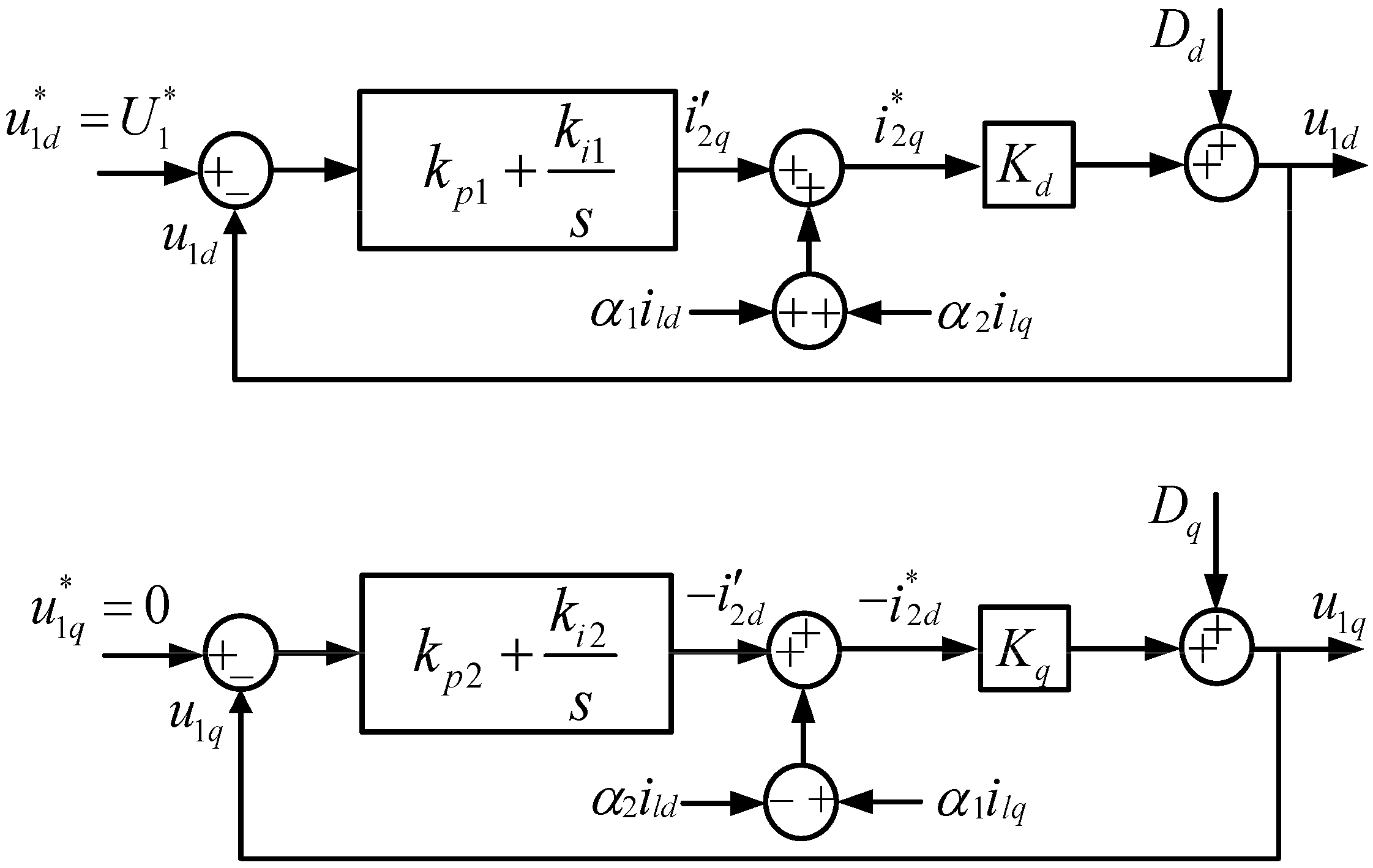
and
. Based on the above analysis, the simplified PW voltage control loop with the MSC compensation can be illustrated in
Figure 4.
4.3. Load Disturbance Suppression Based on LSC
The tractional LSC control scheme adopts the unit-power-factor operation mode, which means the LSC reactive current is zero. And, generally, the active current of LSC is only used to regulate the dc bus voltage. Hence, the capabilities of LSC have not been fully exploited.
With the PW voltage orientation, i1d and i1q can be regarded as the active and reactive currents of PW. If the LSC can utilize the stored dc bus energy to provide instantaneous power to the load during load increasing, the instantaneous power that the PW needs to provide would be reduced, which means that the PW active and reactive currents i1d and i1q can be significantly decreased, thereby suppressing the impact of load disturbance on the PW voltage.
Therefore, from the preceding analysis, the reference current for the LSC can be derived as follows:
where
denotes the output signal from the PI controller regulating the dc bus voltage.
According to Equation (36), the final
d- and
q-axis reference values
and
are obtained by adding the corresponding feedforward terms
and
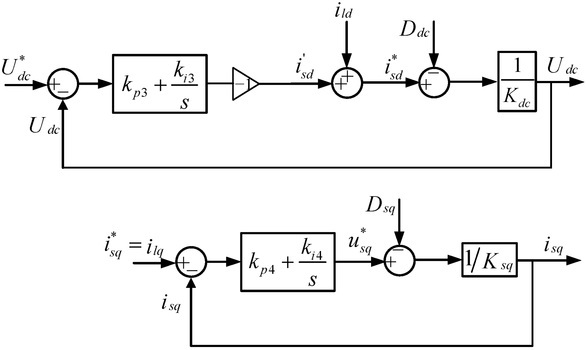
to the LSC current control loop. Thus, based on the basic LSC control strategy, the improved dc bus voltage and current control loop of LSC for load disturbance suppression can be shown in
Figure 5, where
Ksq indicates the open-loop first-order transfer function from
isq to LSC
q-axis voltage
usq, and
Kdc represents that from the dc bus voltage
Udc to
isq.
4.4. Coordinated Control for Load Disturbance Suppression
From the above analysis, it can be seen that using the LSC to compensate the load current will make the dc bus voltage drop more obvious. When the dc bus voltage drops below the PW line voltage amplitude, the rectifier will not work properly. For the MSC, the capacity is also a big problem, and the insufficient capacity will also affect the compensation effect. Therefore, considering the capacity of both the MSC and LSC, the coordinated control of them is required.
Some other works on dual-converter control of BDFIG have been carried out in [
24,
25]. However, Ref. [
24] emphasizes the coordinated control of converters under unbalanced loads, and [
25] focuses on the coordinated control method of the double-side converters for standalone BDFIG under nonlinear load. In addition, Ref. [
25] employs the weight coefficient λ to allocate the contributions of the two converters to harmonic suppression. Similarly, this study also distributes the load current compensation according to the weight coefficient
λ.
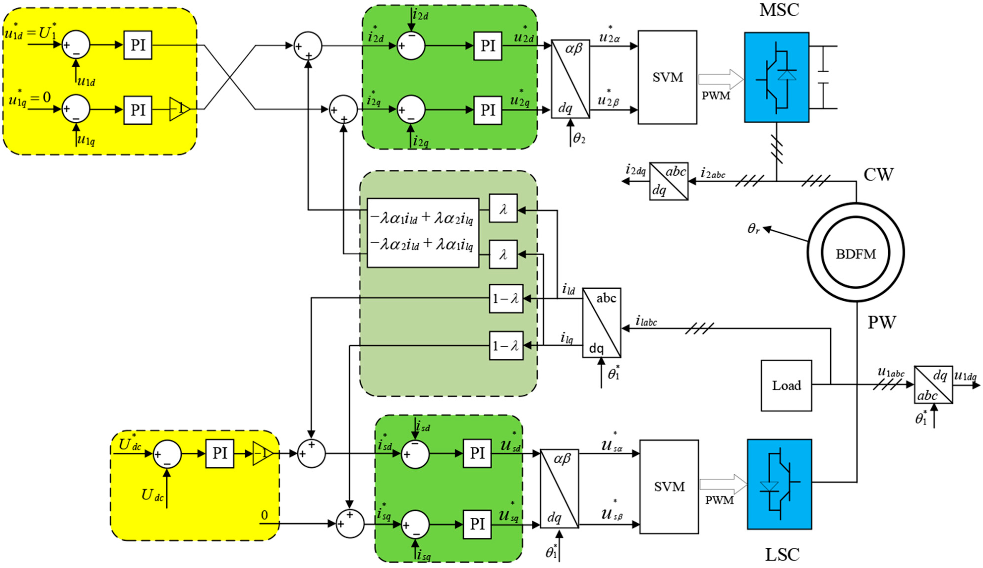
For the control of the MSC, the
d- and
q-axis components of the PW voltage are separately regulated by PI controllers. The outputs of the PI controllers are then added to compensation terms derived from the coefficient
λ and the load current, yielding the
d- and
q-axis reference values for the CW current. Subsequently, PI control is applied separately to the
d- and
q-axis components of the CW current to generate the required output voltage for the converter. Regarding the control of the LSC, the dc bus voltage is regulated by a PI controller. The PI output is added to a compensation term obtained from the coefficient
λ and the load current to produce the
d-axis reference value for the LSC current. The
q-axis reference value for the LSC current is derived directly from the compensation term based on the weight coefficient
λ and the load current. Finally, a separate PI control is applied to the
d- and
q-axis components of the LSC current to generate the required output voltage for the converter. The overall control block diagram is shown in
Figure 6.
6. Conclusions
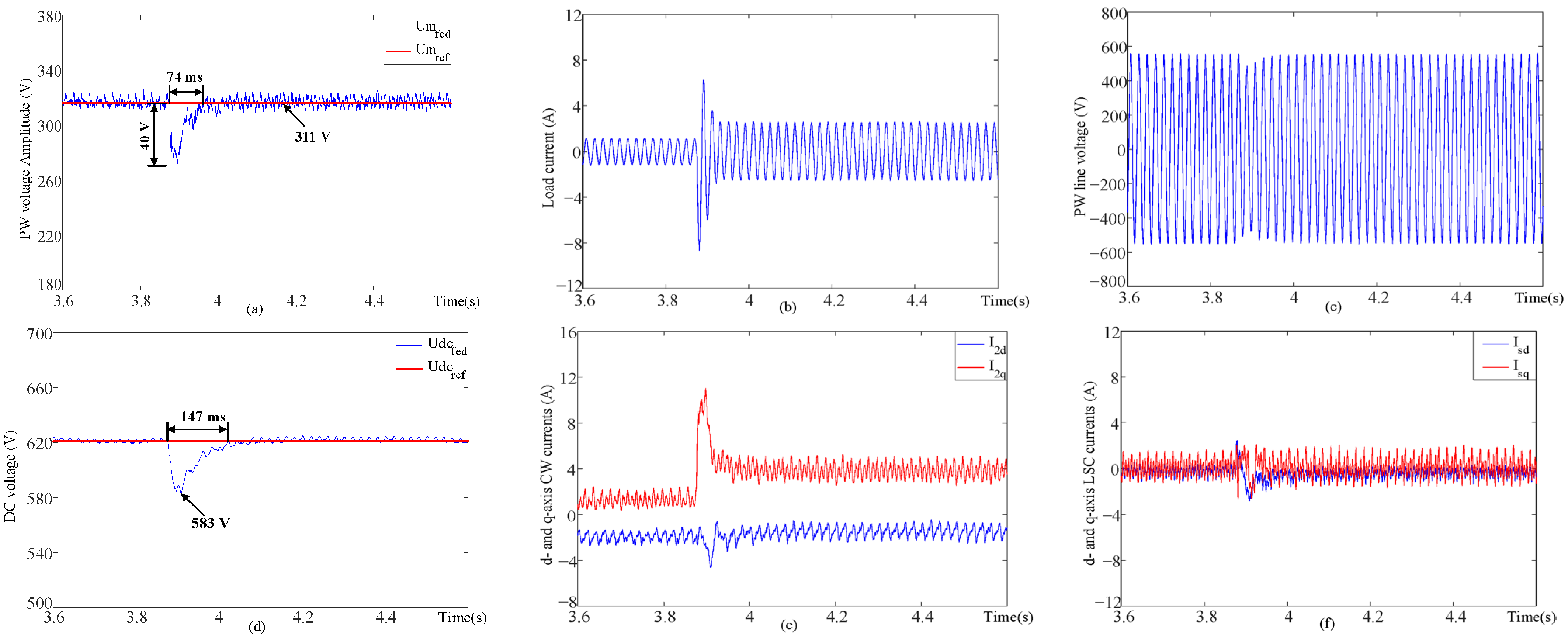
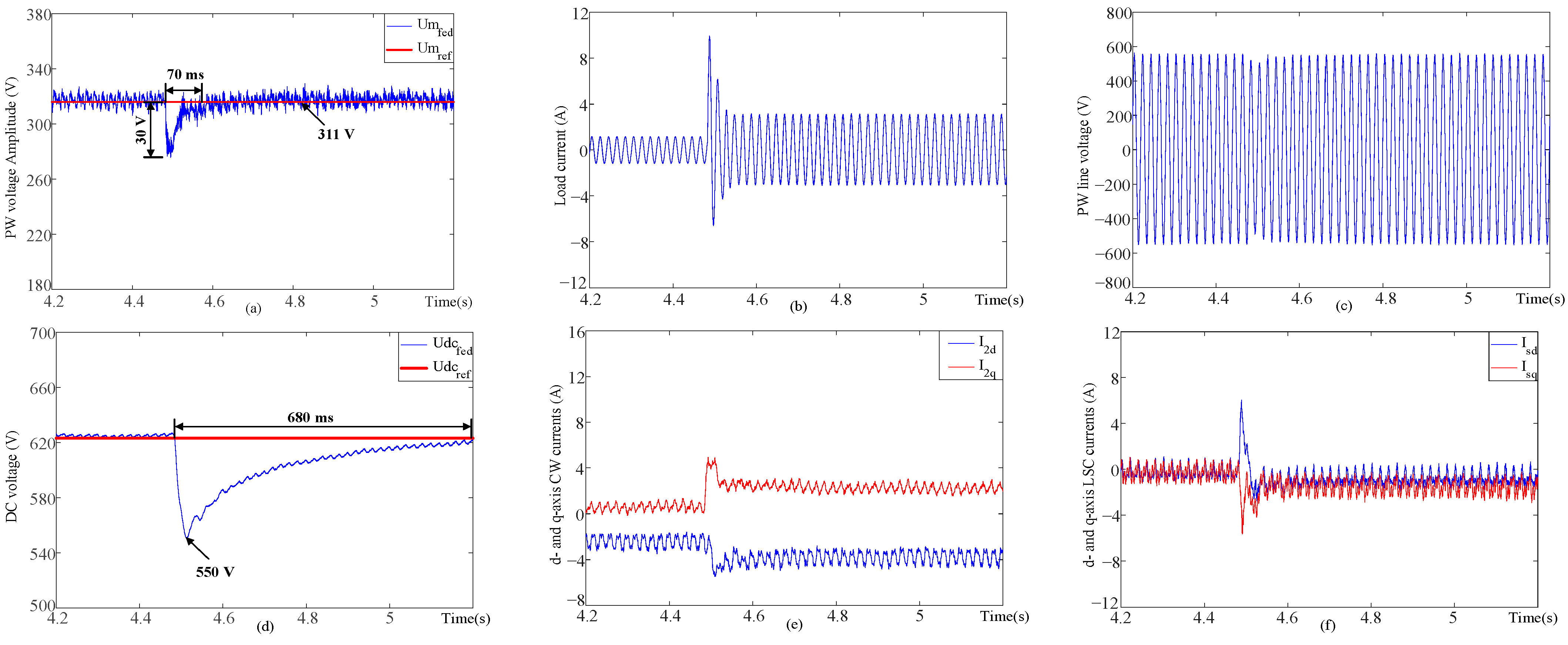
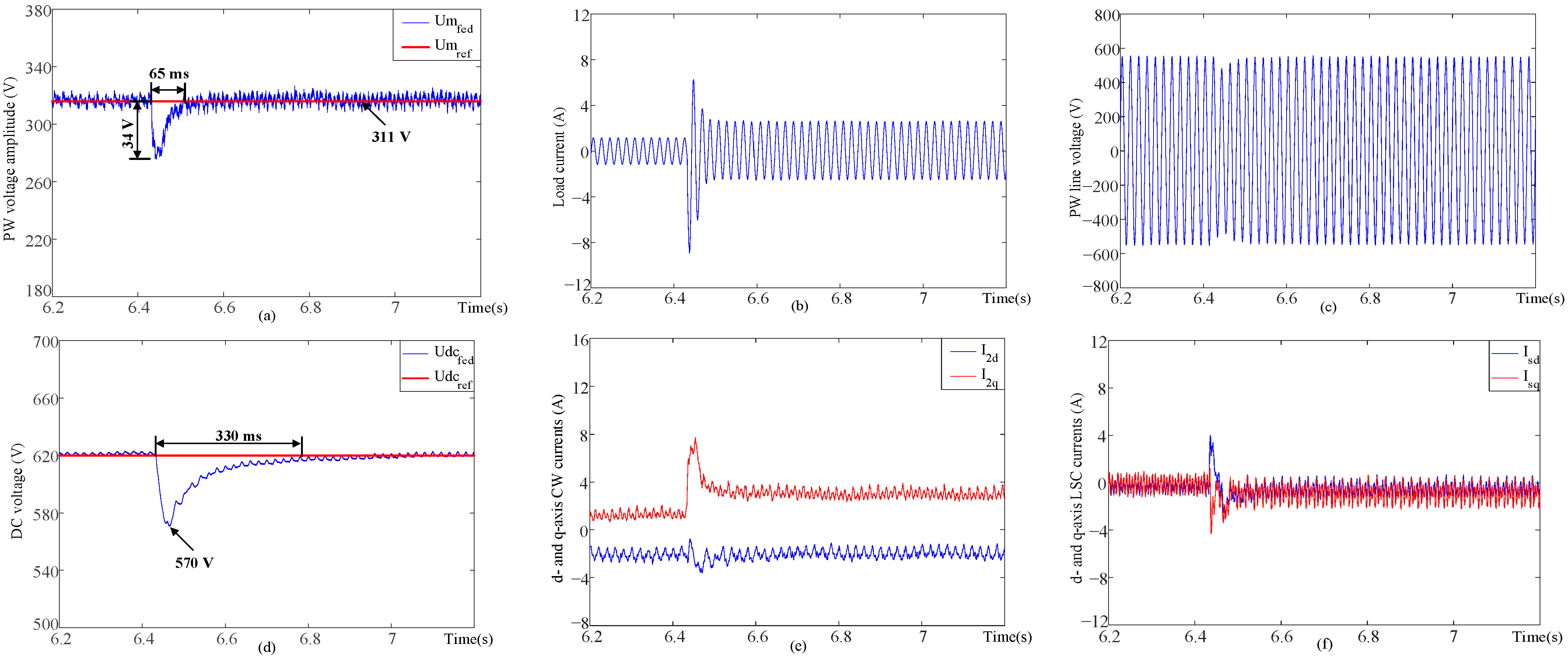
This paper proposes a cooperative control method based on both MSC and LSC to enhance standalone BDFIG system performance under load disturbances. Experimental results on a 3 kW prototype demonstrate that the proposed method effectively suppresses the PW voltage fluctuation and accelerates the transient response. Comparative tests show that the MSC compensation strategy primarily improves the dc bus voltage stability, while the LSC compensation strategy mainly enhances the anti-disturbance performance of the PW voltage. Combining the advantages of both MSC and LSC compensation, the proposed cooperative compensation strategy achieves satisfactory PW voltage dip with the short settling time, while maintaining acceptable performance on the dc bus voltage. The innovation of this paper lies in its coordinated control method that leverages the redundant capacity of both MSC and LSC, which quantitatively demonstrates a 62% reduction in voltage dip and a 43% faster settling time compared to the uncompensated scheme under heavy load disturbance.
The integration of the system with energy storage or the adoption of multi-machine systems may further enhance the load disturbance rejection capability. Since energy storage devices can provide additional reactive power, the LSC could theoretically achieve stronger capability for load disturbance suppression. However, the coordinated control of the BDFIG and the energy storage requires further investigation. For multi-machine systems, although the overall disturbance regulation capacity may be improved, voltage coordination at the PCC may introduce new challenges, which also warrants further research.