Article

Combustion Characteristics of Oil-Impregnated Sorbent Under Different Heating Conditions

1
Polytechnic School, Siberian Federal University, 79 Svobodny Avenue, Krasnoyarsk 660041, Russia
2
Research School of High-Energy Physics, National Research Tomsk Polytechnic University, 30 Lenin Avenue, Tomsk 634050, Russia
3
Institute of Chemistry and Chemical Technology, Siberian Branch of Russian Academy of Sciences, 50/24 Akademgorodok, Krasnoyarsk 660036, Russia
*
Author to whom correspondence should be addressed.
Energies 2026, 19(18), 4435; https://doi.org/10.3390/en19184435 (registering DOI)
Submission received: 31 July 2026 / Revised: 6 September 2026 / Accepted: 16 September 2026 / Published: 19 September 2026

Abstract

In the present study, using advanced methodologies together with analytical and experimental equipment, the ignition and combustion characteristics were determined for coal-based fuels, sorbent derived from this coal, and oil-impregnated sorbent (33.3 wt.% oil), as well as blended compositions of coal with oil-impregnated sorbent, where the mass fraction of the latter in the mixture was varied from 10 to 30%. By means of simultaneous thermal analysis, high-speed video recording under radiant-convective (500–800 °C) and radiant-conductive (600–1000 °C) heating conditions, and flue gas composition analysis, the principal combustion patterns and characteristics of the fuel set were established. The following parameters were determined: ignition temperature Ti, burnout temperature Tb, maximum Rmax and mean Rmean mass loss rates, integral combustion index S, ignition delay time td, as well as CO, CO2, and NOx concentrations in the flue gases. The experimental results indicate that the addition of 20% oil-impregnated sorbent to coal yields the maximum combustion index (3.18 min−2·°C−3) and the lowest burnout temperature (537 °C), whereas at a 10% addition, the highest burnout efficiency (98.4%) and the shortest ignition delay time in a heated air flow are achieved. Co-combustion of coal with 10–20% oil-impregnated sorbent is a promising approach for spent sorbent utilization while maintaining high energy performance of solid fuel combustion.

1. Introduction

Nearly 1.5 million cubic meters of petroleum products enter water annually. Approximately 45% of these releases are of natural origin, and about 5% of oil enters water as a result of extraction and production processes, while transportation accidents account for 22% of such spills. The remaining oil enters water because of minor accidents and leaks, which often go unnoticed [1].
The problem of disposing of petroleum-impregnated sorbents during the cleanup of emergency spills remains highly relevant due to a combination of environmental, economic, and regulatory challenges [2]. The sorption method, being one of the most common and effective techniques for recovering oil and petroleum products, generates a significant volume of spent materials requiring further disposal, and it is at this waste management stage that the main difficulties arise. The simplest and least expensive option remains landfilling at specialized sites; however, this approach carries substantial environmental risks [3,4,5,6,7]. Due to hydrocarbon desorption, secondary environmental contamination may occur, which is particularly hazardous when petroleum products migrate into soil horizons and groundwater. Moreover, the allocation of large land areas for landfills becomes an additional constraining factor under conditions of limited resources.
Alternative methods, such as thermal incineration, sorbent regeneration, biodegradation, or fuel briquette production, also have limitations [8,9,10,11]. Incineration involves the risk of toxic emissions and high energy consumption; regeneration requires sophisticated equipment and allows only a limited number of reuse cycles; biological methods are characterized by long processing times and dependence on climatic conditions; processing into fuel necessitates additional technological treatment and quality control of the final product.
The problem is particularly acute in northern and Arctic regions, where low temperatures slow down the natural degradation of hydrocarbons, fragile ecosystems exhibit increased vulnerability to secondary contamination, and logistical difficulties in transporting waste to specialized facilities significantly raise the cost of disposal [12]. Therefore, promising approaches to addressing the problem include the development of biodegradable sorbents based on renewable feedstocks (peat, lignin, agricultural waste), the improvement of regeneration technologies enabling the recovery of up to 90% of petroleum products, the implementation of circular economy principles that involve using production waste for the manufacture of sorbents followed by their energy utilization, as well as the digitalization of waste tracking systems and landfill monitoring [13,14,15,16,17,18,19].
In this context, one of the most practice-oriented and economically sound solutions is the thermal utilization of petroleum-impregnated sorbents in coal-fired boilers by their metered addition to the primary fuel. Oil-contaminated sorbents possess a high calorific value comparable to that of low-grade coals, which allows not only for effective waste neutralization but also for partial substitution of fossil fuels, thereby reducing energy supply costs for enterprises [20,21]. When combusted in equipped boiler facilities with modern gas cleaning systems, emissions can be controlled, and the resulting ash may be utilized together with ash and slag wastes or used in the construction industry, provided that environmental standards are met [22,23]. Thus, the transition from the linear “collect–landfill” model to integrated, environmentally oriented solutions, including co-combustion with coal, is a prerequisite for ensuring the sustainable development of oil spill response technologies and minimizing long-term environmental impacts.
The aim of this work is a comprehensive study of the ignition and combustion characteristics of composite fuels based on coal and oil-impregnated sorbent at different mass ratios of the components, including the characteristics of the resulting flue gases, under various heating conditions.
This study addresses key scientific questions using a range of modern methods and equipment. These include calorimetry, TG–DTG–DSC analysis, high-speed video recording of fuel ignition and combustion under radiant-convective and radiant-conductive heating, and flue gas composition analysis. The work focuses on three main research questions:
  • The first question examines how the addition of oil-impregnated sorbent to coal affects the kinetic parameters of combustion. Specifically, we consider the combustion index S and the burnout temperature Tb. This allows us to assess the controllability of co-combustion of the sorbent with brown coal for energy generation. It also contributes to expanding the range of available fuel components.
  • The second question investigates the mechanisms that occur during heating of fuels based on coal and oil-impregnated sorbent. It also examines the physicochemical characteristics that affect ignition delay times (td). This enables us to establish the regularities of ignition and combustion for the fuels under consideration.
  • The third question aims to determine the optimal content of the additive (oil-impregnated sorbent) in coal fuel. The goal is to strike a balance between the fuel’s energy characteristics and its environmental performance, including flue gas emissions.

2. Materials and Methods

2.1. Materials

In this work, the following fuel components were investigated: brown coal, Borodinsky open-pit mine, Krasnoyarsk Region, Russia; sorbent derived from brown coal; oil, Yurubcheno-Tokhomskoye oil and gas condensate field, Krasnoyarsk Region, Russia.
Table 1 presents the component composition of the fuels.
Brown coal is used as a low-grade energy fuel for heat and power generation at thermal power facilities.
The sorbent was obtained under laboratory conditions by gasification of brown coal in a batch-type experimental setup using a well-known sorbent production technology. All technical parameters of the sorbent are described in detail in several publications [24,25]. A laboratory-scale vertical cylindrical gasifier with a cross-section of 100 mm and a working height of 1000 mm was used to produce the sorbent. The temperature inside the gasifier was maintained at approximately 900 °C and was monitored by five thermocouples. The blast was supplied through a nozzle located at the bottom of the gasifier, with an air flow rate of 2.7 m3/h. A thermal wave was initiated by forced heating of the upper coal layer and subsequently propagated downward, countercurrent to the blast flow (Figure 1). The producer gas generated during the process was removed through a special nozzle located at the top of the gasifier.
The oil used in this study is widely available in the Krasnoyarsk Region of Russia and is commonly processed at oil refineries.
The preparation of the oil-impregnated sorbent (composition No. 4) was carried out as follows. The mass of the dry sorbent and the mass of the oil were preliminarily determined using Vibra AJ-420 CE laboratory balances (Vibra, Tokyo, Japan). The amount of each component was calculated so that the mass fraction of oil in the final sample was 33.3%. After weighing, the sorbent was placed into a container, and the required amount of oil was added. The resulting mixture was thoroughly stirred mechanically for 5 min until a visually uniform distribution of oil throughout the sorbent volume was achieved. After stirring, the sample was kept in a sealed container for 24 h at room temperature to ensure uniform distribution of oil within the porous structure of the sorbent.
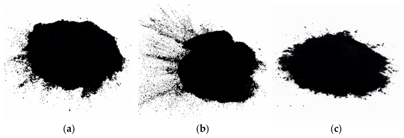
To evaluate the feasibility of thermal utilization of the spent sorbent (oil-impregnated) in coal-fired boilers, three blends based on brown coal and oil-impregnated sorbent were prepared: No. 5–No. 7 (Figure 2). For each blend, the mass of brown coal and the mass of the impregnated sorbent were preliminarily determined using laboratory balances according to the specified component ratios (90 wt.% brown coal and 10 wt.% oil-impregnated sorbent (composition No. 5); 80 wt.% brown coal and 20 wt.% oil-impregnated sorbent (composition No. 6); 70 wt.% brown coal and 30 wt.% oil-impregnated sorbent (composition No. 7)). After weighing, the components were mechanically mixed for 5 min until a homogeneous state was achieved. The prepared blends were kept in hermetically sealed containers for 24 h to ensure uniform distribution of the oil.
The prepared compositions were stored in containers with airtight lids to prevent oil evaporation and moisture ingress from the environment. Immediately prior to the experiments, each composition was additionally mixed for at least 5 min.

2.2. Proximate and Ultimate Analysis

Preparation of the solid fuel samples (brown coal, sorbent) was carried out by mechanical grinding in a Retsch DM200 crusher (Retsch GmbH, Haan, Germany) to a particle size of less than 1 mm. To obtain the 0.14–0.25 mm size fraction, corresponding to pulverized combustion conditions in power plants, a Retsch AS200 vibratory sieve classifier (Retsch GmbH, Haan, Germany) equipped with calibrated sieves in accordance with [26] was used. The liquid fuel was not subjected to any additional preparation prior to analysis.
A comprehensive set of physicochemical analyses was then performed for compositions No. 1–No. 3. The moisture content was determined using an MA-150 moisture analyzer (Sartorius AG, Göttingen, Germany) in accordance with [27]. Ash content on a dry basis was determined by calcination in a Snol 7.2/1300 muffle furnace (AB Umega Group, Utena, Lithuania) according to [28]. Volatile matter yield on a dry ash-free basis was also assessed using the same furnace in compliance with [29]. The net calorific value (lower heating value) in the as-received state was measured using a C6000 automatic calorimeter (IKA-Werke GmbH & Co. KG, Staufen, Germany) following [30]. The elemental composition (carbon, hydrogen, nitrogen) on a dry ash-free basis was determined according to [31]. Sulfur content was measured in accordance with [32]. Oxygen content was calculated by difference [33]. A summary of the experimental results is presented in Table 2.

2.3. Thermal Analysis and Determination of the Main Combustion Parameters

The study of thermal decomposition and oxidation processes of the samples was performed using a NETZSCH STA 449 F1 Jupiter synchronous thermal analyzer (NETZSCH-Gerätebau GmbH, Selb, Germany), which allows simultaneous recording of mass changes and heat flows. The experimental procedure involved simulation of conditions close to real combustion processes: air with a controlled flow rate of 50 mL/min was used as the oxidizing atmosphere, and temperature programming was performed in a linear mode at a heating rate of 10 °C/min. The fuel sample mass was 11 ± 0.3 mg (no more than half of the crucible volume) and depended on the bulk density of the fuel. Primary processing of the thermogravimetric curves and calculation of the derivatives (DTG) were performed using the specialized software Proteus Thermal Analysis 5.1.0. To verify the data and eliminate random errors, each experiment was duplicated, which is a critically important step, since fuel heterogeneity may lead to scatter of results even within a single sample.
The peak rate of thermal decomposition of the sample, recorded as the extremum on the differential thermogravimetric (DTG) curve, served as a quantitative measure of the intensity of oxidative transformations. The temperature limits for the onset of thermal oxidation (ignition temperature Ti) and for the completion of the process (burnout temperature Tb) were determined by the geometric method, based on drawing tangents to the sections of the curve and identifying their intersection points. This approach is widely validated in the scientific literature [34,35,36,37]. For an integral comparative assessment of the reactivity of disparate fuel systems characterized by variations in elemental composition and thermophysical constants, a dimensionless criterion—the combustion index (S, min−2 °C−3)—was applied. It had been successfully validated in previous studies [38,39,40,41]. This parameter exhibits a direct correlation with process efficiency: an increase in the numerical value of S indicates more favorable kinetic characteristics of the fuel, ensuring its accelerated and complete oxidation. The combustion index S was calculated according to the analytical expression (1) [38,39,40,41]:
S = R max R mean T i 2 T b × 10 7
where the parameter Rmax characterizes the maximum rate of thermo-oxidative degradation, defined as the maximum on the differential mass loss curve (DTG), which corresponds to the highest intensity of volatile release or combustion rate (%/min); the parameter Rmean represents the average rate of thermo-oxidative degradation over the operating temperature range from the initiation of the exothermic reaction to the completion of the main burnout stage (%/min).

2.4. Radiant-Convective Heating of Fuels

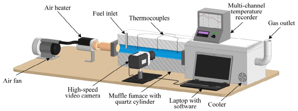
An experimental study of the ignition and combustion characteristics of the fuels was carried out under radiant-convective heating conditions using a laboratory setup and a previously validated procedure [42]. The setup consists of the following main components: a ROBUST high-pressure air blower (LEISTER, Wuppertal, Germany), a LEISTER LE 5000 HT air heater (LEISTER, Wuppertal, Germany), a General Therm RT 1000.1100 SP tubular muffle furnace (Nevaterm, Saint Petersburg, Russia), an RMT-59 multi-channel temperature recorder (Elemer, Zelenograd, Russia), and a V411 high-speed video camera (Vision Research, Wayne, NJ, USA). A 3D model of the experimental setup is shown in Figure 3.
The flow of heated air was supplied into the quartz cylinder by a ROBUST air blower in conjunction with a LEISTER LE 5000 HT air heater. The air flow velocity was 5 m/s. Uniform temperature distribution along the length of the quartz cylinder was maintained using a General Therm RT 1000.1100 SP tubular muffle furnace. The temperature of the air flow was recorded by three type-K thermocouples connected to an RMT-59 multi-channel temperature recorder. After passing through the muffle furnace, the hot exhaust air was directed through an air cooler and then discharged to the atmosphere by an exhaust ventilation system.
In each experiment, the ignition delay times (td) of the test fuels were recorded. For coal, sorbent, and their blends, a series of 5–10 experiments were conducted at air flow temperatures Ta = 500–800 °C. A fuel sample weighing approximately 5 mg was introduced into the air stream through a ceramic channel. The onset of ignition delay timing t = 0 corresponded to the moment when the fine solid particles were introduced into the air stream. The ignition of a particle in the heated air flow was considered the end of the ignition delay time measurement, t = td. The processes occurring during the movement of fine solid particles inside the quartz cylinder were recorded by a Phantom V411 high-speed color video camera equipped with a Distagon 1.4/35 ZF.2 T* wide-angle lens. The recording rate was 4000 frames per second at a resolution of 1008 × 80 pixels. Automated processing of the video recordings for determining the ignition delay times (td) was carried out using Phantom Camera Control 3.0 software according to a previously validated procedure [42]. The systematic uncertainty in the determination of td, associated with the video recording rate, does not exceed 0.5%, while the random uncertainty due to scatter of the experimental data is 15%.

2.5. Radiant-Conductive Heating of Fuels

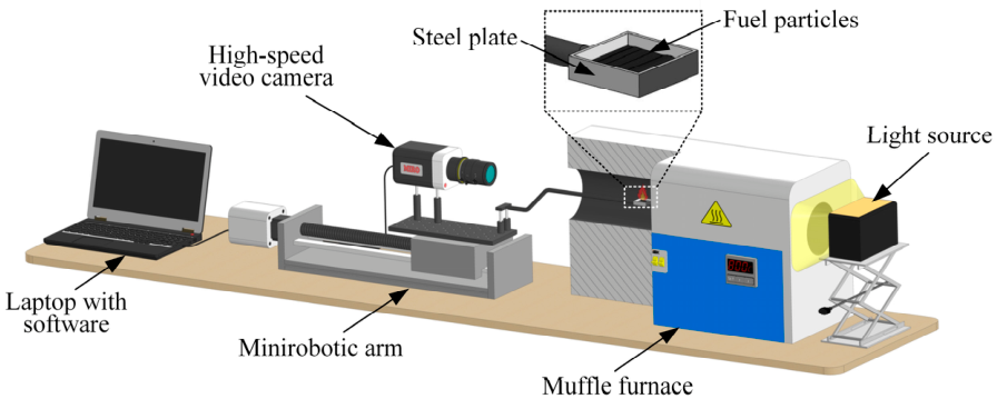
A series of experiments on the ignition and combustion processes of fuels under radiant-conductive heating conditions was performed using an experimental setup, a 3D model of which is shown in Figure 4. The experiments were conducted in an air atmosphere under laboratory conditions at an ambient temperature of 23 °C, atmospheric pressure, and 45% humidity.
The high-temperature air environment (Tg = 600–1000 °C) was generated in the working chamber of a Nabertherm R 50/250/13 tubular muffle furnace (Nabertherm GmbH, Lilienthal, Germany). The openings of the tubular muffle furnace were left open on both sides, allowing free air exchange with the environment without forced convection. In each series, consisting of 5–10 experiments, the furnace was preheated to the target temperature Tg. Fuel samples weighing 0.1 g, preliminarily weighed on ViBRA AF-225DRCE analytical balances (with a maximum permissible absolute error of ±1 mg; Shinko Denshi Co., Ltd., Tokyo, Japan), were placed onto a steel substrate (internal dimensions 8 × 8 × 5 mm). Using an SPSH20-23017/2000Z coordinate mechanism ("Zavod Mekhatronnykh Izdely", Povarovo, Russia), the substrate with the fuel was introduced into the muffle furnace chamber along the axis of symmetry of the ceramic tube to its midpoint (Figure 4); the displacement speed did not exceed 0.1 m/s. Prior to insertion into the muffle furnace, the initial temperature of the substrate was maintained constant (corresponding to the laboratory ambient temperature of 23 °C) and measured with a Raytek RAYMX2TDU pyrometer (measurement range from −30 to 1000 °C, accuracy ± 0.75% or ±1 °C, whichever is greater; Raytek Corporation, Berlin, Germany). The fast-occurring processes were recorded using a Phantom V411 high-speed video camera (Vision Research, USA), mounted on a coordinate mechanism, and a PC equipped with the Tema Automotive commercial 3.9 software (Image Systems AB, Linköping, Sweden). The recording rate was 1000 frames per second at a resolution of 800 × 600 pixels. After each experiment, the solid combustion residue was removed from the substrate surface (fuel heating surface) by purging with an air stream at a pressure of 10 atm. To improve image contrast during video recording, a light source was used.
During each experiment, the gas-phase ignition delay times (td) of the test fuels were recorded. The start of the ignition delay timing (t = 0) corresponded to the moment when the substrate with the fuel began to be heated at the entrance to the muffle furnace tube. The ignition of the gas–vapor mixture was considered to be the end of the ignition delay time measurement, t = td. The ignition moment was recorded automatically using a video processing algorithm when the luminosity intensity threshold was reached or exceeded at any point of the video recording area [43]. The systematic uncertainty in the determination of td, associated with the video recording rate, does not exceed 0.5%, while the random uncertainty due to scatter of the experimental data is 10%.

2.6. Flue Gas Analysis

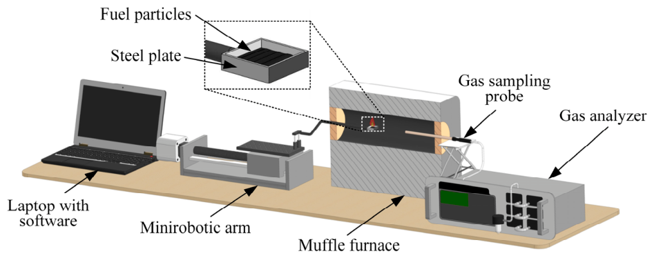
To determine the component composition of the flue gases generated during combustion of the test fuels and their blends, gas analysis was performed. The experiments were conducted on a laboratory setup, a 3D model of which is shown in Figure 5.
The combustion of the fuel samples was carried out in a Nabertherm R 50/250/13 tubular muffle furnace (Nabertherm, Germany). The flue gas composition was analyzed using a pre-calibrated, in accordance with the manufacturer’s instructions, Test 1 gas analyzer (Boner LLC, Novosibirsk, Russia) equipped with electrochemical sensors: O2 (range 0–25%, absolute error ± 0.2%); CO (range 0–40,000 ppm, relative error ± 5%); SO2 (range 0–1000 ppm, relative error ± 5%); NO (range 0–2000 ppm, relative error ± 5%); NO2 (range 0–500 ppm, relative error ± 7%); H2S (range 0–500 ppm, relative error ± 5%); and HCl (range 0–2000 ppm, relative error ± 5%). In addition, the gas analyzer is equipped with optical sensors for CO2 (range 0–30%, reduced error ± 2%), CH4 (range 0–30%, reduced error ± 5%), and CO (range 0–30%, reduced error ± 5%), as well as a polarographic H2 sensor (range 0–5%, absolute error ± 5%). The gas analyzer includes a modular probe, a condensate trap, and a filtration system designed for drying and cleaning the extracted gas sample.
Fuel supply to the combustion zone was provided by an SPSH20-23017/2000Z coordinate mechanism (“Zavod Mekhatronnykh Izdely”, Russia), which was controlled from a laptop using dedicated software.
The temperature in the working chamber of the furnace was maintained at 800 °C. Once the target temperature had been reached, a fuel sample weighing 0.1 g, preliminarily weighed on ViBRA AF-225DRCE analytical balances (Shinko Denshi Co., Ltd., Japan), was introduced into the muffle furnace using the coordinate mechanism. To reduce heat losses and prevent gas exchange with the ambient environment, the furnace inlet was sealed with a layer of thermal insulation material. On the opposite side of the furnace, the modular probe of the gas analyzer was inserted, and the gap around it was also sealed with thermal insulation.
After the fuel sample was introduced into the muffle furnace and the openings of the tubular muffle furnace were closed, the gas analyzer continuously sampled the combustion products through a probe. The flue gases passed through drying and filtration stages before entering the measuring unit of the gas analyzer, where the concentrations of the components were recorded every 1 s. The flow rate of the gas analyzer pump was 0.3 L/min. The total internal volume of the sampling system, including the volume of the Nabertherm R 50/250/13 muffle furnace tube, the probe, connecting lines, condensate trap, and filtration system, was approximately 0.5 L. Upon completion of each experiment, the gas sampling tube was purged with atmospheric air to remove residual combustion products. To ensure reliability of the results, each series consisted of at least 5 experiments conducted under identical initial conditions.

3. Results and Discussion

3.1. Combustion of Fuels Under Slow Heating Conditions

To comprehensively evaluate the feasibility of utilizing spent sorbent (e.g., after oil spill cleanup) through partial co-combustion with coal in a coal-fired boiler, the main combustion parameters of the fuels under study were determined under slow heating conditions. For this purpose, thermogravimetric analysis (TGA) was employed.
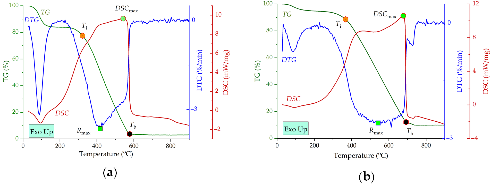
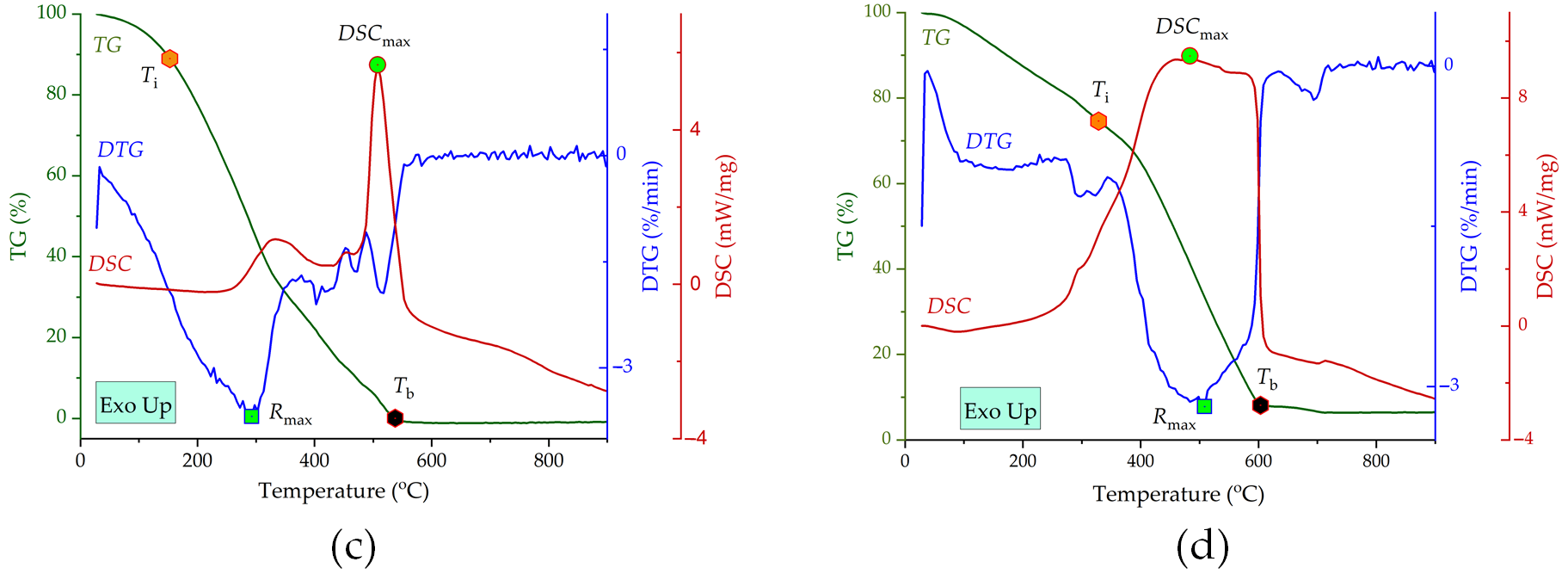
Figure 6 presents the heating curves for the individual fuels No. 1–No. 3 (coal, sorbent, and oil), as well as the heating curves for fuel No. 4 (oil-impregnated sorbent). The main combustion characteristics of the fuels under slow heating are summarized in Table 3.
For solid fuels, the entire heating process can be divided into three main stages: (1) moisture removal; (2) volatile release and combustion; and (3) combustion of the coke residue together with remaining volatiles. The first stage for solid fuels No. 1, No. 2, and No. 4 occurs in the temperature range of 30–120 °C (Figure 6a,b,d) and is accompanied by a mass loss due to water evaporation. The second stage for the solid fuels proceeds in the following temperature ranges: No. 1—120–322.9 °C; No. 2—120–366.2 °C; and No. 4—120–329.9 °C. The ignition temperature of the impregnated sorbent is lower than that of the raw sorbent. This is attributed to the low-temperature oxidation of the oil present in the sorbent pores. The third stage, involving combustion of the coke residue and burnout of volatiles, occurs in the following temperature ranges: No. 1—322.9–574.0 °C; No. 2—366.2–689.0 °C; and No. 4—329.9–600 °C. The combustion process for the solid fuels is completed at the following temperatures: No. 1—574.0 °C; No. 2—689.0 °C; and No. 4—600 °C (Figure 6a,b,d). The maximum heat flow intensity was observed for the sorbent, reaching 10.6 mW/mg. The highest combustion index value was recorded for coal (Table 3).
A comparison of sorbent combustion before and after impregnation with oil revealed that the combustion of the coke residue of the oil-impregnated sorbent (No. 4) shifts to a lower temperature range compared with the raw sorbent (No. 2). This is attributed to earlier ignition of the coke residue (Figure 6b,d). The temperature at which the maximum mass loss rate (i.e., the maximum combustion rate) was achieved was 505.8 °C for fuel No. 4 (oil-impregnated sorbent) and 540.0 °C for fuel No. 2 (raw sorbent). A decrease in the burnout temperature was observed for fuel No. 4, along with an increase in the combustion index compared with fuel No. 2 (Table 3).
During heating of oil (fuel No. 3, Figure 6c), a low-temperature oxidation process occurs in the temperature range of 130–380 °C, with an ignition temperature of 152.6 °C. The maximum mass loss rate is observed at 290.4 °C, reaching 3.75%/min, while the heat flow intensity is relatively low at approximately 1.17 mW/mg. The second stage proceeds in the temperature range of 380–542 °C and is characterized as high-temperature oxidation. This stage is accompanied by the most intense exothermic reaction at 508 °C, with a heat flow intensity of up to 5.7 mW/mg, while the maximum mass loss rate is 1.94%/min. The combustion process for oil is completed at 542 °C (Figure 6c). Among all fuels studied (No. 1–No. 4), the highest combustion efficiency was observed for oil, with a combustion index of 7.24 min−2·°C−3 (Table 3).
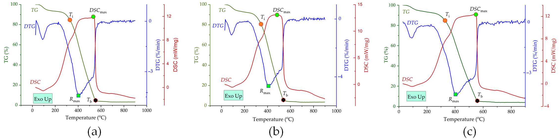
Figure 7 presents the TG, DTG, and DSC heating curves for composite fuels No. 5–No. 7.
During the first stage of heating, in the temperature range of 30–120 °C, moisture removal occurs and is accompanied by an endothermic effect. Upon further heating, the second stage begins (occurring from 120 °C up to the ignition temperature of the coke residue). This stage corresponds to the onset of low-molecular bond breaking, accompanied by the release of gaseous volatiles contained in the coal and oil. The ignition temperatures of the coke residue for composite fuels No. 5, No. 6, and No. 7 are 326.2, 342.0, and 330.0 °C, respectively (Table 3). Further heating initiates the third stage, in which combustion of the coke residue of coal and sorbent takes place. This stage proceeds in the following temperature ranges: fuel No. 5—326.2–550 °C; fuel No. 6—342.0–537.0 °C; and fuel No. 7—330.0–559.0 °C (Figure 7).
According to the thermogravimetric analysis results, among fuels No. 5–No. 7, the addition of 20% oil-impregnated sorbent to coal gave the highest combustion index value of 3.18 min−2·°C−3 and the lowest burnout temperature of 537 °C, indicating more efficient combustion. In addition, fuel No. 6 exhibited the highest mass loss rate of 4.66%/min and the highest heat flow intensity of 13.1 mW/mg. However, a further increase in the mass fraction of oil-impregnated sorbent in the blend was found to deteriorate the main combustion parameters under slow heating conditions.
Compared with pure coal, the addition of 10% oil-impregnated sorbent improves the combustion process under slow heating conditions. This is evidenced by an increase in the combustion index and the maximum mass loss rate, as well as a decrease in the burnout temperature. In addition, the combustion of the coke residue shifts to a lower temperature range relative to that of coal (Table 3). Similar results have been reported in studies on co-combustion of coal and liquid petroleum products. It was found that an increase in the fuel oil content in the mixture raises the DTG peak values, which in turn leads to higher combustion index values [44]. This supports the feasibility of utilizing spent sorbent in coal-fired boilers.

3.2. Combustion of Fuels Under Radiant-Convective Heating Conditions

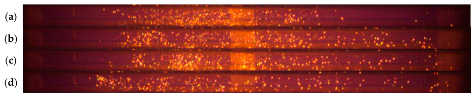
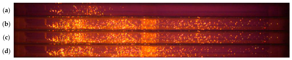
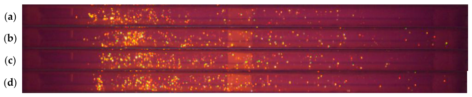
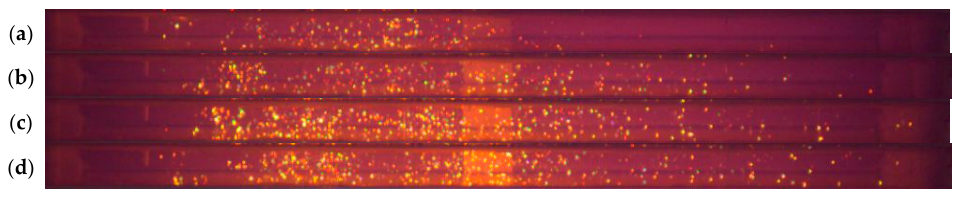
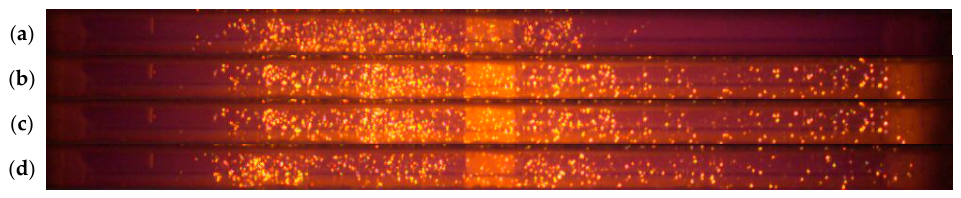
Typical frames from high-speed video recording of the ignition and combustion processes of fuel particles under radiant-convective heating conditions are presented in Figure 8, Figure 9, Figure 10, Figure 11 and Figure 12. The video frames were recorded at intervals of ∆t = 0.01 s from the moment of fuel ignition.
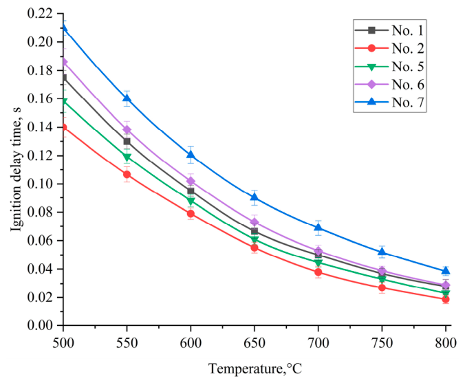
From the results obtained (Figure 8, Figure 9, Figure 10, Figure 11 and Figure 12), it can be seen that composition No. 7 is characterized by the longest ignition delay time. The sorbent derived from brown coal (composition No. 2) ignites faster. The addition of oil-impregnated sorbent to coal at a content of 10% reduces the ignition delay time, while the addition of 20% and 30% increases it (Figure 13).
The highest reactivity, and consequently the lowest ignition delay times throughout the entire temperature range studied (from 500 to 800 °C), is exhibited by composition No. 2 (Figure 13). At 500 °C, the ignition delay time for sorbent No. 2 is 0.1400 s, while for brown coal (composition No. 1) it is 0.1750 s. After fine coal particles (composition No. 1) are introduced into the heated air flow, almost all heat supplied by the external source is consumed by endothermic processes of phase transformation (moisture evaporation) and thermal decomposition, both of which absorb heat [45]. As a result, an evaporation front forms inside the particles and a temperature gradient develops, increasing the time required to heat the particle to its ignition temperature. In addition, coal has a relatively dense structure with predominantly closed pores with respect to the external gas environment [46]. Therefore, coal (composition No. 1) requires more energy (and consequently more time) for the development of heterogeneous combustion, unlike the sorbent derived from it (composition No. 2). Moreover, the high reactivity of the sorbent in a heated air flow is associated with the almost complete absence of moisture and volatiles in its composition (Table 2). On the DSC curves of coal (composition No. 1) (Figure 6a), an endothermic effect is registered in the low-temperature region (around 100 °C), which is caused by a phase transition of the liquid increasing the heating time of the coal particles. Due to this, the sorbent particles are characterized by faster heating. Owing to the developed specific surface area and porosity of the sorbent, the oxidizer penetrates into the porous structure and interacts with the carbon framework, reducing the ignition delay time (Figure 13).
The ignition delay times of raw coal (composition No. 1) occupy an intermediate position in the ignition delay plot, lying below the delay curves of compositions No. 6 and No. 7, but above that of composition No. 5. The addition of oil-impregnated sorbent to coal has an ambiguous effect on the ignition delay time. On the one hand, increasing the mass fraction of impregnated sorbent to 20% (composition No. 6) and 30% (composition No. 7) leads to an increase in ignition delay time compared to coal by 4–35%. The decrease in the reactivity of the blends may be caused by particle agglomeration due to the presence of the liquid phase (oil). This leads to a reduction in the specific contact area with the oxidizer and an increase in the heating time of the fuel particles. On the other hand, the addition of 10% oil-impregnated sorbent (composition No. 5) provides a pronounced synergistic effect, reducing the ignition delay times by 10–18%. The addition of 10% oil-impregnated sorbent to coal does not cause significant particle agglomeration, while the small amount of oil creates local zones with a combustible gas–vapor mixture, which intensify the ignition process.
The experimental data obtained in this study are in good agreement with known trends for radiant-convective heating of composite fuels [42,43,46,47]. It has been shown that the addition of components such as biomass or liquid combustible materials reduces ignition delay times by up to 57%, depending on the component composition, ambient temperature, and particle size (when solid additives are used). This reduction is attributed to the presence of volatile components and the porous structure of the particles. These findings confirm that oil-impregnated sorbent can be used as a coal additive not only for utilizing spent sorbent, but also for enhancing the energy performance of fossil fuel.

3.3. Combustion of Fuels Under Radiant-Conductive Heating Conditions

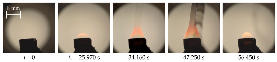
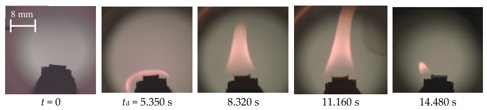
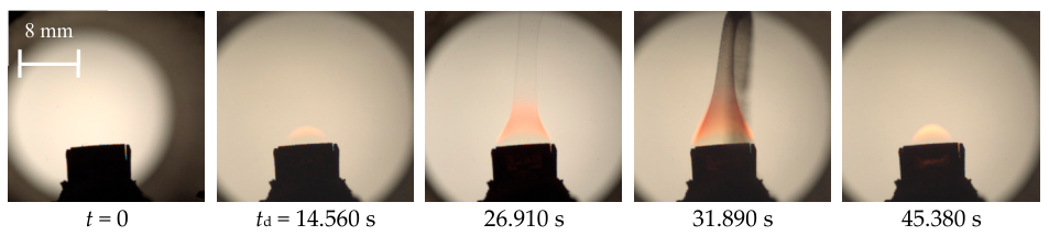
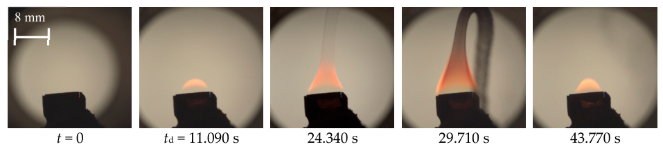
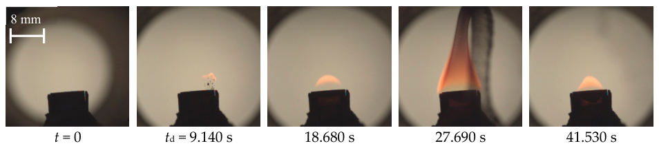
Typical frames from high-speed video recording of the ignition and combustion processes of brown coal particles (composition No. 1), brown-coal-derived sorbent impregnated with oil (composition No. 4), and their blends at different mass ratios (compositions No. 5, No. 6, and No. 7) under radiant-conductive heating conditions are presented in Figure 14, Figure 15, Figure 16, Figure 17 and Figure 18. Gas-phase ignition of the raw brown-coal-derived sorbent particles (composition No. 2) was not detected.
From the results obtained (Figure 14, Figure 15, Figure 16, Figure 17 and Figure 18), it can be seen that the combustion process of the individual fuels and fuel blends is characterized by monotonic burnout of the fuel particles. The brown-coal-derived sorbent impregnated with oil (composition No. 4) ignites faster than the brown coal particles (composition No. 1) (Figure 14 and Figure 15). The addition of oil-impregnated sorbent to coal in various mass ratios reduces the ignition delay times (Figure 16, Figure 17 and Figure 18).
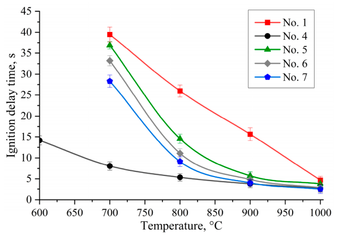
Figure 19 presents the dependences of the ignition delay times of fuel particles under radiant-conductive heating on the temperature in the tubular muffle furnace (600–1000 °C). The approximation curves are drawn through the points representing the mean ignition delay times (td) of the fuel particles, established in a series of 5–10 experiments under identical initial conditions.
In contrast to radiant-convective heating (Figure 8, Figure 9, Figure 10, Figure 11 and Figure 12), where ignition of individual fuel particles occurs, under radiant-conductive heating, the heat is supplied to the layer placed on a steel substrate. This results in a temperature gradient across the layer thickness, from the surface and the substrate walls toward the center.
As the muffle furnace temperature increases, the ignition delay times (td) of the fuel particles decrease, since at Tg→1000 °C the processes of heating and moisture evaporation proceed most intensively. The ignition temperature of the oil-impregnated sorbent particles (composition No. 4) is 600 °C, whereas the other compositions ignite at the minimum furnace temperature of 700 °C. During heating of the sorbent layer impregnated with a combustible liquid (composition No. 4), the volatile component (oil) begins to evaporate from the porous structure of the sorbent. A combustible vapor–gas mixture then forms above the substrate surface. When the required concentration and temperature are reached, this mixture ignites. Moreover, due to the larger amount of oil in composition No. 4, the concentration of combustible vapors at 600 °C is sufficient for ignition of this composition compared with the other fuels (Figure 19).
The addition of oil-impregnated sorbent to brown coal in various mass ratios reduces the ignition delay times by 44–65% compared to raw coal (at 800 °C). At 800 °C, the td values for the blends were as follows: No. 5—14.560 s, No. 6—11.090 s, and No. 7—9.140 s. This is because an increase in the oil content of the fuel mixture raises the total content of volatile combustible components (Table 2), which form a combustible vapor–gas mixture above the substrate surface. Consequently, the vapor–gas concentration required for ignition is reached more quickly, and the ignition delay times decrease.
During the experiments, the raw brown-coal-derived sorbent (composition No. 2) did not exhibit gas-phase ignition over the entire temperature range studied. Upon heating of composition No. 2 in the muffle furnace, heterogeneous surface oxidation occurred without visible flame formation. The absence of gas-phase ignition is explained by the fact that the raw sorbent does not contain sufficient moisture and volatile matter (Table 2), which are required for the formation of a combustible gas–vapor mixture.
It was found that under radiant-conductive heating conditions, ignition delay times decrease with an increase in the fraction of sorbent impregnated with a combustible liquid in the fuel composition. A similar trend has been reported for coal slurries with the addition of combustible liquids and biomass [42,48,49,50,51]. In those studies, the dominant role of gas-phase exothermic reactions of volatile components in reducing the induction period during heating of fuel mixtures was also noted. It should be noted, however, that the number of published studies on the combustion of combustible-liquid-impregnated sorbents with coal is limited.

3.4. Analysis of Flue Gas Composition

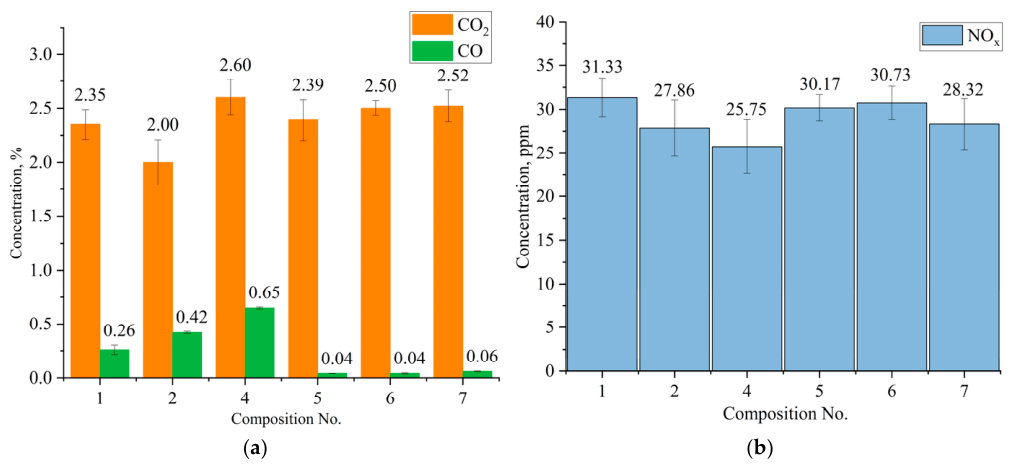
Figure 20 presents the average concentrations of CO, CO2, and NOx obtained during combustion of the compositions in the tubular muffle furnace at 800 °C.
The results obtained allow the modified combustion efficiency (MCE) of the test fuels to be assessed (Table 4). MCE was calculated using the following Formula (2) [52]:
M C E = C O 2 C O 2 + C O × 100 % .
It was found that the combustion of brown coal (composition No. 1), brown-coal-derived sorbent (composition No. 2), and oil-impregnated sorbent (composition No. 4) proceeds with a relatively low MCE. This is indicated by the high level of carbon monoxide (CO) formation, which is the main indicator of chemical underburning and reaches a maximum of 0.65% for the oil-impregnated sorbent (Table 4). Physically, this is explained by the release of volatile matter during heating, which does not have sufficient time to react with atmospheric oxygen, creating local zones with an excess of fuel.
A pronounced positive effect is observed when moving to the blended compositions. The optimal composition is No. 5. This fuel blend demonstrates the maximum combustion efficiency (CO concentration drops to 0.04%) with the minimum average CO2 emissions among all blends. A relatively small amount of oil in the fuel blend promotes faster ignition (Figure 19) and complete burnout of the composition. With a further increase in the fraction of oil-impregnated sorbent (compositions No. 6 and No. 7), the combustion efficiency decreases, accompanied by an increase in CO2 concentration in the flue gases.
The concentrations of nitrogen oxides (NOₓ) in the flue gases produced during combustion of the fuel compositions differed only slightly. This is attributed to the relatively low fuel nitrogen content (Table 2). In addition, the active formation of nitrogen oxides occurs at temperatures above 1300 °C; therefore, at the muffle furnace temperature of 800 °C, no significant NOₓ formation took place. The stability of this parameter indicates that the addition of oil-impregnated sorbent does not disrupt the overall nitrogen balance of the fuel.
The introduction of organic additives and biomass into coal fuel results in a pronounced environmental effect, reducing anthropogenic gas emissions [42,46,51]. Increasing the concentration of vegetable components in the fuel led to significant sequestration of sulfur and nitrogen oxides [50]. In the present work, combustion of coal with oil-impregnated sorbent resulted in a reduction of up to 85% in carbon monoxide emissions and up to 10% in nitrogen oxide emissions compared with unmodified coal. These findings indicate that the approach of utilizing spent sorbents through co-combustion with fossil fuel is promising.
In accordance with the results of the experimental studies, the numerical values of the main characteristics obtained are presented in Table 5.
Analysis of the results presented in Table 5 shows a significant improvement in the combustion characteristics of the blended fuels compared to raw coal (composition No. 1). The highest reactivity in terms of the combustion index S is characteristic of composition No. 6. Under radiant-convective heating, the shortest ignition delay time is exhibited by composition No. 2, while among the blends, composition No. 5 ignites the fastest. Under radiant-conductive heating, the minimum ignition delay time is characteristic of composition No. 4, and the higher the content of oil-impregnated sorbent in the blend, the shorter the ignition delay time. The results of the flue gas composition analysis indicate a reduction in carbon monoxide emissions when coal is combusted with the addition of oil-impregnated sorbent, with the minimum concentrations being characteristic of compositions No. 5 and No. 6. In terms of carbon dioxide and nitrogen oxide emissions, the lowest values were recorded for compositions No. 2 and No. 4, respectively, while raw brown coal is characterized by the maximum nitrogen oxide emissions. Comparison of the characteristics studied, taking into account the balance between energy efficiency and environmental safety, allows compositions No. 5 and No. 6 (with the addition of 10 and 20% of oil-impregnated sorbent to coal, respectively) to be identified as optimal for practical implementation.
The results of this study have shown that oil-impregnated sorbent can be utilized through co-combustion with coal. However, the practical implementation of this approach at an industrial scale requires consideration of design and technological features when upgrading boiler equipment and managing ash and slag waste. The addition of a liquid phase (oil) to coal increases the adhesive properties of the fuel. This may cause particles to stick to equipment walls and disrupt the stability of fuel feeding into the combustion chamber, necessitating modernization of the fuel supply systems. The presence of sorbent in the fuel blend also alters the chemical composition of the fuel, which may lower the ash melting point and lead to slagging of heating surfaces. For practical application of the fuels studied in this work, further comprehensive research is required. Such studies should focus on a detailed investigation of the effects of the blended fuel on equipment performance and the environmental characteristics of ash and slag waste.

4. Conclusions

A comprehensive study of the combustion characteristics of composite fuels based on coal and oil-impregnated sorbent has been carried out under different heating conditions, with consideration of gaseous product formation. The following patterns and characteristics have been established:
  • The thermal analysis results show that the addition of 10 to 30% oil-impregnated sorbent to coal increases the ignition temperature by up to 6%, while the burnout temperature decreases by 7% compared to coal. The combustion index of the composite fuels increases by up to 62% compared with brown coal, indicating improved combustion efficiency of the composite blend.
  • Under radiant-convective heating conditions (at 500–800 °C), the shortest ignition delay time is observed for the raw sorbent. Among the blends, the shortest ignition delay time is recorded for the composition with 10% oil-impregnated sorbent (composition No. 5) over the entire temperature range studied. Increasing the proportion to 20% and 30% leads to an increase in the ignition delay time. The decrease in the reactivity of the blends may be caused by particle agglomeration due to the presence of the liquid phase (oil).
  • Under radiant-conductive heating (600–1000 °C), the minimum temperature required for ignition of composition No. 4 is 600 °C. Compositions No. 1, No. 5, No. 6, and No. 7 ignite steadily at a tubular muffle furnace temperature of 700 °C. The addition of oil-impregnated sorbent to coal contributes to a reduction in ignition delay times of up to 74% compared with raw coal. The raw sorbent does not exhibit gas-phase ignition over the entire temperature range investigated.
  • The concentration of carbon dioxide during combustion of the compositions varies in the range from 2.00 to 2.60%. At the same time, nitrogen oxide emissions from the different fuel compositions differ only slightly. The addition of oil-impregnated sorbent to coal improves environmental safety by reducing toxic CO emissions.
Thus, considering the balance between energy efficiency and environmental safety, the compositions with 10 and 20% oil-impregnated sorbent added to coal can be identified as optimal for practical implementation.

Author Contributions

Conceptualization, A.Z. and D.G.; methodology, A.P., P.K. and E.H.; software, G.G. and Y.Z.; validation, A.P., A.Z. and P.K.; formal analysis, T.P.; investigation, A.P., K.G. and A.Z.; resources, A.Z.; data curation, E.H., G.G. and A.P.; writing—original draft preparation, A.P. and A.Z.; writing—review and editing, A.P., A.Z. and D.G.; visualization, A.P., K.G. and Y.Z.; supervision, A.Z. and D.G.; project administration, A.Z.; funding acquisition, A.Z. All authors have read and agreed to the published version of the manuscript.

Funding

This research was supported by the Russian Science Foundation [grant number 26-19-20002. https://rscf.ru/en/project/26-19-20002/ (accessed on 30 July 2026)] with targeted funding (grant) from the Krasnoyarsk Regional Science Foundation.

Data Availability Statement

The data presented in this study are available on request from the corresponding author. The data are not publicly available due to confidentiality reasons.

Conflicts of Interest

The authors declare no conflicts of interest.

References

  1. Alekseev, D.V.; Lentarev, A.A.; Federation, R. Comparative Analysis of Databases on Oil and Petroleum Products Spills from Ships. Vestn. Gos. Univ. Morskogo I Rechn. Flot. Im. Admirala S. O. Makarova 2022, 14, 891–904. [Google Scholar] [CrossRef] [Scilit]
  2. Bhardwaj, N.; Bhaskarwar, A.N. A Review on Sorbent Devices for Oil-Spill Control. Environ. Pollut. 2018, 243, 1758–1771. [Google Scholar] [CrossRef] [Scilit] [PubMed]
  3. Mao, J.; Deng, W.; Zhao, M.; Li, J. Recent Advances in Waste-Derived Sorbents for Oil Sorption and Oil–Water Separation: Progress and Future Prospects. Sep. Purif. Technol. 2026, 402, 138659. [Google Scholar] [CrossRef] [Scilit]
  4. de Folly d’Auris, A.; Rubertelli, F.; Taini, A.; Vocciante, M. A Novel Polyurethane-Based Sorbent Material for Oil Spills Management. J. Environ. Chem. Eng. 2023, 11, 111386. [Google Scholar] [CrossRef] [Scilit]
  5. da Silva Soares, W.; de Moura, L.G.M.; de Santana, C.G.; da Silva, D.C.; Cardoso, J.J.F. Sustainable Cork-Derived Biosorbents for the Removal of Petroleum Oil from Produced Water: Performance, Functionalization Efficiency and Industrial Feasibility. Sustain. Chem. One World 2026, 10, 100240. [Google Scholar] [CrossRef] [Scilit]
  6. Basuliman, M.M.; Zango, Z.U.; Trache, D.; Mohamad Ibrahim, M.N.; Hussin, M.H. A Mini-Review on Lignin Isolation and Modification Based on Sorbent Materials with Porous Nature as Demulsifier for Oil/Water Separations. Int. J. Biol. Macromol. 2025, 318, 145064. [Google Scholar] [CrossRef] [Scilit] [PubMed]
  7. Naseem, M.; Sultan, M.; ul Islam, M.; Kareem, A.; Ali, N.; Khan, I.; Ahmad, S.; Nawaz, F.; Khan, A.; Ali, F.; et al. Superhydrophilic Wettability Porous Materials from Construction Tooil/Water Separation Applications. Fuel 2025, 386, 134195. [Google Scholar] [CrossRef] [Scilit]
  8. Byun, S.; Park, S.; Lee, E.; An, A.K.; Jeong, S. Joule-Heating Electrospun Reduced-Graphene Oxide Nanoribbon-Coated Reusable Polymeric Sorbent with an Excellent Sorption/Desorption of High-Viscosity Oils. Carbon 2024, 219, 118826. [Google Scholar] [CrossRef] [Scilit]
  9. Baskar, A.V.; Bolan, N.; Hoang, S.A.; Sooriyakumar, P.; Kumar, M.; Singh, L.; Jasemizad, T.; Padhye, L.P.; Singh, G.; Vinu, A.; et al. Recovery, Regeneration and Sustainable Management of Spent Adsorbents from Wastewater Treatment Streams: A Review. Sci. Total Environ. 2022, 822, 153555. [Google Scholar] [CrossRef] [Scilit] [PubMed]
  10. Kozyatnyk, I.; Yacout, D.M.M.; Van Caneghem, J.; Jansson, S. Comparative Environmental Assessment of End-of-Life Carbonaceous Water Treatment Adsorbents. Bioresour. Technol. 2020, 302, 122866. [Google Scholar] [CrossRef] [Scilit] [PubMed]
  11. Wang, G.; Sun, Q.; Zhang, Y.; Fan, J.; Ma, L. Sorption and Regeneration of Magnetic Exfoliated Graphite as a New Sorbent for Oil Pollution. Desalination 2010, 263, 183–188. [Google Scholar] [CrossRef] [Scilit]
  12. Du, M.; Guo, R.; Wu, W.; Shi, H.; Shi, F.; Liu, J.; Ning, Y.; Zheng, Q. Low-Cost, Superhydrophobic Ramie Weave Structure for Efficient Oil Spill Recovery in Ice Zones in All Weather and Heavy Sea Conditions. J. Environ. Chem. Eng. 2025, 13, 117976. [Google Scholar] [CrossRef] [Scilit]
  13. Sajid, M.; Algreiby, A.A.; Alrebdi, G.S.; Alluhayb, A.H. Recent Advances in Biomass-Based Sorbents for the Extraction of Analytes in Environmental, Food, and Biological Samples. TrAC Trends Anal. Chem. 2025, 192, 118377. [Google Scholar] [CrossRef] [Scilit]
  14. Zhang, W.; Liu, Y.; Tao, F.; An, Y.; Zhong, Y.; Liu, Z.; Hu, Z.; Zhang, X.; Wang, X. An Overview of Biomass-Based Oil/Water Separation Materials. Sep. Purif. Technol. 2023, 316, 123767. [Google Scholar] [CrossRef] [Scilit]
  15. Suni, S.; Kosunen, A.-L.; Hautala, M.; Pasila, A.; Romantschuk, M. Use of a By-Product of Peat Excavation, Cotton Grass Fibre, as a Sorbent for Oil-Spills. Mar. Pollut. Bull. 2004, 49, 916–921. [Google Scholar] [CrossRef] [Scilit] [PubMed]
  16. Yang, L.; Wang, Z.; Yang, L.; Li, X.; Zhang, Y.; Lu, C. Coco Peat Powder as a Source of Magnetic Sorbent for Selective Oil–Water Separation. Ind. Crops Prod. 2017, 101, 1–10. [Google Scholar] [CrossRef] [Scilit]
  17. Ji, Q.; Liu, J.; Nan, T.; Su, L.; Boateng, I.D.; Li, Z.; Zhou, C.; Liu, X. Turning Lignin Waste into Functional Sorbents for Environmental Remediation. Int. J. Biol. Macromol. 2026, 340, 149896. [Google Scholar] [CrossRef] [Scilit] [PubMed]
  18. Smyk, N.; Tkachenko, O.; Sevastyanova, O.; Budnyak, T.M. PH-Switchable Kraft Lignin/Silica Gel Sorbent for Tunable Removal of Organic and Inorganic Water Contaminants. Colloids Surf. A Physicochem. Eng. Asp. 2025, 726, 137814. [Google Scholar] [CrossRef] [Scilit]
  19. Antonelli, L.; Felli, N.; De Cesaris, M.G.; Cinti, S.; Gentili, A. From Waste to Sorbent: Recycling Polymers and Natural Materials for Sample Preparation and Water Remediation. Talanta 2026, 301, 129263. [Google Scholar] [CrossRef] [Scilit] [PubMed]
  20. Karakasi, O.K.; Moutsatsou, A. By-Products: Oil Sorbents as a Potential Energy Source. Waste Manag. Res. J. Sustain. Circ. Econ. 2013, 31, 376–383. [Google Scholar] [CrossRef] [Scilit] [PubMed]
  21. Sadeghi, A. Co-Pyrolysis of Solid Oily Waste for Efficient Waste Reduction and Energy Recovery in Marine Oil Spill Response. Master’s Thesis, University of Northern British Columbia, Prince George, BC, Canada, 2023. [Google Scholar] [CrossRef] [Scilit]
  22. Ram, S.; Tare, M.S.; Aswath, P.B.; Ralegaonkar, R.V. Potential of Co-Fired Fly Ashes as a Construction Material—A Review. In Encyclopedia of Renewable and Sustainable Materials; Elsevier: Amsterdam, The Netherlands, 2020; pp. 674–685. [Google Scholar] [CrossRef] [Scilit]
  23. Elliott, A.; Mahmood, T.; Kamal, A. Boiler Ash Utilization in the Canadian Pulp and Paper Industry. J. Environ. Manag. 2022, 319, 115728. [Google Scholar] [CrossRef] [Scilit] [PubMed]
  24. Mikhaliov, I.O.; Islamov, S.R. Experimental Investigation into the Process of Fixed-Bed Coal Gasification with Reversed Air Blowing. Combust. Explos. Shock Waves 2009, 45, 686–691. [Google Scholar] [CrossRef] [Scilit]
  25. Zhuikov, A.; Pyanykh, T.; Grishina, I.; Chicherin, S.; Zhuikova, Y. Thermogravimetric Analysis of Combustion of Semi-Coke Obtained from Coniferous Wood and Mixtures on Their Basis. Fire 2024, 7, 385. [Google Scholar] [CrossRef] [Scilit]
  26. ISO 3310-1:2016; Test Sieves—Technical Requirements and Testing—Part 1: Test Sieves of Metal Wire Cloth. ISO (International Organization for Standardization): Geneva, Switzerland, 2016.
  27. ISO 18134-1:2022; Solid Biofuels—Determination of Moisture Content—Part 1: Total Moisture—Reference Method. ISO (International Organization for Standardization): Geneva, Switzerland, 2022.
  28. ISO 18122:2022; Solid Biofuels—Determination of Ash Content. ISO (International Organization for Standardization): Geneva, Switzerland, 2022.
  29. ISO 18123:2023; Solid Biofuels —Determination of Volatile Matter. ISO (International Organization for Standardization): Geneva, Switzerland, 2023.
  30. ISO 18125:2017; Solid Biofuels—Determination of Calorific Value. ISO (International Organization for Standardization): Geneva, Switzerland, 2017.
  31. ISO 16948:2015; Solid Biofuels—Determination of Total Content of Carbon, Hydrogen and Nitrogen. ISO (International Organization for Standardization): Geneva, Switzerland, 2015.
  32. ISO 16994:2016; Solid Biofuels—Determination of Total Content of Sulfur and Chlorine. ISO (International Organization for Standardization): Geneva, Switzerland, 2016.
  33. ISO/TS 20048-1:2020; Solid Biofuels—Determination of Off-Gassing and Oxygen Depletion Characteristics—Part 1: Laboratory Method for the Determination of Off-Gassing and Oxygen Depletion Using Closed Canisters. ISO (International Organization for Standardization): Geneva, Switzerland, 2020.
  34. Isaac, K.; Bada, S.O. The Co-Combustion Performance and Reaction Kinetics of Refuse Derived Fuels with South African High Ash Coal. Heliyon 2020, 6, e03309. [Google Scholar] [CrossRef] [Scilit] [PubMed]
  35. Wang, C.; Wang, F.; Yang, Q.; Liang, R. Thermogravimetric Studies of the Behavior of Wheat Straw with Added Coal during Combustion. Biomass Bioenergy 2009, 33, 50–56. [Google Scholar] [CrossRef] [Scilit]
  36. Zhuikov, A.V.; Glushkov, D.O.; Kuznetsov, P.N.; Grishina, I.I.; Samoilo, A.S. Ignition of Two-Component and Three-Component Fuel Mixtures Based on Brown Coal and Char under Slow Heating Conditions. J. Therm. Anal. Calorim. 2022, 147, 11965–11976. [Google Scholar] [CrossRef] [Scilit]
  37. Raza, M.; Abu-Jdayil, B.; Al-Marzouqi, A.H.; Inayat, A. Kinetic and Thermodynamic Analyses of Date Palm Surface Fibers Pyrolysis Using Coats-Redfern Method. Renew. Energy 2022, 183, 67–77. [Google Scholar] [CrossRef] [Scilit]
  38. Liu, Z.; Quek, A.; Kent Hoekman, S.; Srinivasan, M.P.; Balasubramanian, R. Thermogravimetric Investigation of Hydrochar-Lignite Co-Combustion. Bioresour. Technol. 2012, 123, 646–652. [Google Scholar] [CrossRef] [Scilit] [PubMed]
  39. Moon, C.; Sung, Y.; Ahn, S.; Kim, T.; Choi, G.; Kim, D. Effect of Blending Ratio on Combustion Performance in Blends of Biomass and Coals of Different Ranks. Exp. Therm. Fluid Sci. 2013, 47, 232–240. [Google Scholar] [CrossRef] [Scilit]
  40. Zhu, G.; Wen, C.; Liu, T.; Xu, M.; Ling, P.; Wen, W.; Li, R. Combustion and Co-Combustion of Biochar: Combustion Performance and Pollutant Emissions. Appl. Energy 2024, 376, 124292. [Google Scholar] [CrossRef] [Scilit]
  41. Oladejo, J.M.; Adegbite, S.; Pang, C.H.; Liu, H.; Parvez, A.M.; Wu, T. A Novel Index for the Study of Synergistic Effects during the Co-Processing of Coal and Biomass. Appl. Energy 2017, 188, 215–225. [Google Scholar] [CrossRef] [Scilit]
  42. Zhuikov, A.; Glushkov, D.; Pleshko, A.; Grishina, I.; Chicherin, S. Co-Combustion of Coal and Biomass: Heating Surface Slagging and Flue Gases. Fire 2025, 8, 106. [Google Scholar] [CrossRef] [Scilit]
  43. Glushkov, D.; Klepikov, D.; Nigay, A.; Paushkina, K.; Pleshko, A. Experimental Research of the Initial Temperature and Additives Effect on the Ignition and Combustion Mechanisms of Composite Liquid Fuel in a High-Temperature Oxidizer. Appl. Sci. 2023, 13, 3501. [Google Scholar] [CrossRef] [Scilit]
  44. Yongju, O.; Zhang, Y. Synergistic Combustion Characteristics of Mixing DPR Korea’s Anthracite and Heavy Fuel Oil. Fuel 2023, 341, 127653. [Google Scholar] [CrossRef] [Scilit]
  45. Glushkov, D.; Zhuikov, A.; Zemlyansky, N.; Pleshko, A.; Fetisova, O.; Kuznetsov, P. Influence of the Composition and Particle Sizes of the Fuel Mixture of Coal and Biomass on the Ignition and Combustion Characteristics. Appl. Sci. 2023, 13, 11060. [Google Scholar] [CrossRef] [Scilit]
  46. Zhuikov, A.V.; Glushkov, D.O.; Tsepenok, A.I.; Pleshko, A.O. Intensification of the Process of Coal Ignition by Adding Biomass under Flame Combustion Conditions. Solid Fuel Chem. 2023, 57, 348–361. [Google Scholar] [CrossRef] [Scilit]
  47. Kuznetsov, G.V.; Yankovskii, S.A. Conditions and Characteristics in Ignition of Composite Fuels Based on Coal with the Addition of Wood. Therm. Eng. 2019, 66, 133–137. [Google Scholar] [CrossRef] [Scilit]
  48. Slyusarskiy, K.V.; Asilbekov, A.K. Features of Ignition and Combustion of Low-Grade Coal Mixed with Pyrolysis Liquid. Power Eng. Res. Equip. Technol. 2024, 26, 151–164. [Google Scholar] [CrossRef] [Scilit]
  49. Vershinina, K.Y.; Shlegel, N.E.E.; Strizhak, P.A.A. Impact of Environmentally Attractive Additives on the Ignition Delay Times of Slurry Fuels: Experimental Study. Fuel 2019, 238, 275–288. [Google Scholar] [CrossRef] [Scilit]
  50. Syrodoy, S.V.; Yu, M.D.; Nigay, N.A.; Purin, M.V. Influence of the Type of Woody Biomass on Energy and Environmental Characteristics of the Thermal Preparation Processes and Ignition of Bio-Water-Coal Fuel Particles. Process Saf. Environ. Prot. 2024, 184, 736–746. [Google Scholar] [CrossRef] [Scilit]
  51. Klepikov, D.; Kudelova, T.; Paushkina, K.; Strizhak, P. Additives to Coal-Based Fuel Pellets for the Intensification of Combustion and Reduction in Anthropogenic Gas Emissions. Appl. Sci. 2020, 10, 6689. [Google Scholar] [CrossRef] [Scilit]
  52. Zhang, L.; Luo, Z.; Li, Y.; Chen, Y.; Du, W.; Li, G.; Cheng, H.; Shen, G.; Tao, S. Optically Measured Black and Particulate Brown Carbon Emission Factors from Real-World Residential Combustion Predominantly Affected by Fuel Differences. Environ. Sci. Technol. 2021, 55, 169–178. [Google Scholar] [CrossRef] [Scilit] [PubMed]
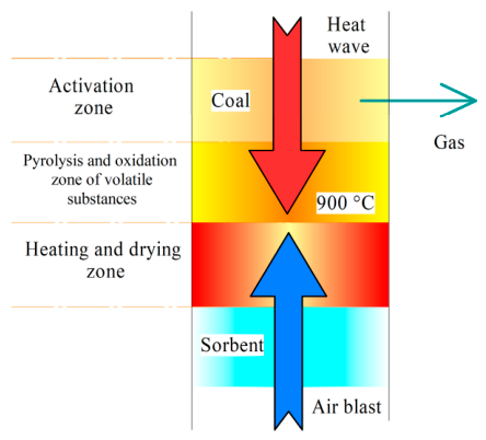
Figure 1. Scheme of the sorbent production process by coal gasification.
Energies 19 04435 g001
Figure 2. Fuel blends: (a) 90 wt.% brown coal and 10 wt.% oil-impregnated sorbent (composition No. 5); (b) 80 wt.% brown coal and 20 wt.% oil-impregnated sorbent (composition No. 6); (c) 70 wt.% brown coal and 30 wt.% oil-impregnated sorbent (composition No. 7).
Energies 19 04435 g002
Figure 3. Model of the experimental setup for fuel combustion under radiant-convective heating conditions.
Energies 19 04435 g003
Figure 4. Model of the experimental setup for fuel combustion under radiant-conductive heating conditions.
Energies 19 04435 g004
Figure 5. Model of the experimental setup for studying the flue gas composition during fuel combustion.
Energies 19 04435 g005
Figure 6. TG, DTG, and DSC heating curves of the fuels: (a) No. 1; (b) No. 2; (c) No. 3; and (d) No. 4. Green line: TG; blue line: DTG; red line: DSC.
Energies 19 04435 g006aEnergies 19 04435 g006b
Figure 7. TG, DTG, and DSC curves of the fuel compositions upon heating: (a) No. 5; (b) No. 6; and (c) No. 7.
Energies 19 04435 g007
Figure 8. Video frames of ignition and combustion of brown coal particles (composition No. 1) in a heated air flow at Ta = 700 °C (Δt = 0.01 s): (a) td = 0.0500 s; (b) t = td + ∆t; (c) t = td + 2∆t; (d) t = td + 3∆t.
Energies 19 04435 g008
Figure 9. Video frames of ignition and combustion of sorbent particles (composition No. 2) in a heated air flow at Ta = 700 °C (Δt = 0.01 s): (a) td = 0.0380 s; (b) t = td + ∆t; (c) t = td + 2∆t; (d) t = td + 3∆t.
Energies 19 04435 g009
Figure 10. Video frames of ignition and combustion of particles of the blend of brown coal and oil-impregnated sorbent (composition No. 5) in a heated air flow at Ta = 700 °C (Δt = 0.01 s): (a) td = 0.0447 s; (b) t = td + ∆t; (c) t = td + 2∆t; (d) t = td + 3∆t.
Energies 19 04435 g010
Figure 11. Video frames of ignition and combustion of particles of the blend of brown coal and oil-impregnated sorbent (composition No. 6) in a heated air flow at Ta = 700 °C (Δt = 0.01 s): (a) td = 0.0530 s; (b) t = td + ∆t; (c) t = td + 2∆t; (d) t = td + 3∆t.
Energies 19 04435 g011
Figure 12. Video frames of ignition and combustion of particles of the blend of brown coal and oil-impregnated sorbent (composition No. 7) in a heated air flow at Ta = 700 °C (Δt = 0.01 s): (a) td = 0.0689 s; (b) t = td + ∆t; (c) t = td + 2∆t; (d) t = td + 3∆t.
Energies 19 04435 g012
Figure 13. Dependences of the ignition delay time of coal, sorbent, and their blends with oil on the oxidizer temperature under radiant-convective heating conditions at Ta = 500–800 °C.
Energies 19 04435 g013
Figure 14. Video frames of ignition and combustion of brown coal particles (composition No. 1) under radiant-conductive heating conditions at Tg = 800 °C.
Energies 19 04435 g014
Figure 15. Video frames of ignition and combustion of oil-impregnated sorbent particles (composition No. 4) under radiant-conductive heating conditions at Tg = 800 °C.
Energies 19 04435 g015
Figure 16. Video frames of ignition and combustion of particles of the blend of brown coal and oil-impregnated sorbent (composition No. 5) under radiant-conductive heating conditions at Tg = 800 °C.
Energies 19 04435 g016
Figure 17. Video frames of ignition and combustion of particles of the blend of brown coal and oil-impregnated sorbent (composition No. 6) under radiant-conductive heating conditions at Tg = 800 °C.
Energies 19 04435 g017
Figure 18. Video frames of ignition and combustion of particles of the blend of brown coal and oil-impregnated sorbent (composition No. 7) under radiant-conductive heating conditions at Tg = 800 °C.
Energies 19 04435 g018
Figure 19. Dependences of the ignition delay times of brown coal (composition No. 1), sorbent (composition No. 2), oil-impregnated sorbent (composition No. 4), and their blends (compositions No. 5, No. 6, and No. 7) on the muffle furnace temperature.
Energies 19 04435 g019
Figure 20. Flue gas composition during combustion of the fuel compositions at 800 °C in the muffle furnace: (a) CO and CO2; (b) NOx.
Energies 19 04435 g020
Table 1. Component composition of the fuels.
FuelsComponent Concentrations, wt.%
Brown CoalSorbentOil
No. 1100--
No. 2-100-
No. 3--100
No. 4-66.733.3
No. 5906.73.3
No. 68013.36.7
No. 77020.010.0
Table 2. Physicochemical properties of the test samples.
FuelsWaAdVdafCdafHdafNdafSdafOdafQri
%MJ/kg
No. 116.13.1048.275.15.30.70.218.715.95
No. 24.79.905.294.12.32.10.11.4029.53
No. 30.30.01-84.614.2001.243.26
No. 41.36.32.789.48.31.10.051.336.40
No. 55.33.243.876.55.60.740.1917.018.68
No. 65.53.638.678.05.90.780.1715.220.04
No. 75.03.933.779.46.20.820.1613.422.09
Wa—moisture in the air-dried sample (%); Ad—ash content on a dry basis (%); Vdaf—volatile matter content on a dry ash-free basis (%); Cdaf, Hdaf, Ndaf, Sdaf, Odaf—carbon, hydrogen, nitrogen, sulfur, and oxygen content on a dry ash-free basis (%); Qri—net calorific value as-received (MJ/kg).
Table 3. Main combustion characteristics of the fuels under slow heating.
FuelTiTmaxTbTDSC *RmaxRmeanSDSCmax
°C%/minMin−2 °C−3mW/mg
No. 1322.9419.85745423.703.171.969.6
No. 2366.2540.06896782.632.50.7110.6
No. 3152.6290.45425083.752.447.245.7
No. 4329.9505.86004883.252.951.059.4
No. 5326.2402.95505334.423.842.9011.9
No. 6342.0402.85374734.664.293.1813.1
No. 7330.0401.45595444.303.692.6112.4
* TDSC—temperature corresponding to DSCmax (°C).
Table 4. Combustion efficiency of the blends.
Component Composition, wt.%DesignationMCE
Brown coalNo. 189.86
Brown-coal-derived sorbentNo. 282.73
Brown-coal-derived sorbent impregnated with oilNo. 479.94
90% brown coal + 10% oil-impregnated sorbentNo. 598.42
80% brown coal + 20% oil-impregnated sorbentNo. 698.33
70% brown coal + 30% oil-impregnated sorbentNo. 797.84
Table 5. Combustion characteristics of the fuels.
Composition No.Combustion Index SRadiant-Convective Heating at Ta = 800 °CRadiant-Conductive Heating at Tg = 800 °CFlue Gases
min−2 °C−3td, cCO, %CO2, %NOx, ppm
11.960.028025.9700.262.3531.33
20.710.0187-0.422.0027.86
41.05-5.3500.652.6025.75
52.900.023014.5600.042.3930.17
63.180.029011.0900.042.5030.73
72.610.03859.1400.062.5228.32
Disclaimer/Publisher’s Note: The statements, opinions and data contained in all publications are solely those of the individual author(s) and contributor(s) and not of MDPI and/or the editor(s). MDPI and/or the editor(s) disclaim responsibility for any injury to people or property resulting from any ideas, methods, instructions or products referred to in the content.