1. Introduction
Harvesting ambient mechanical vibration to power small autonomous electronic devices has become an active area of energy research, motivated by the goal of reducing or eliminating the batteries that are costly to service and to replace [
1]. Among the candidate transduction principles, piezoelectric conversion is the most widely adopted because of its high-power density, favourable scaling and mechanical simplicity [
2]. The archetypal device is a piezoceramic-laminated cantilever operated near resonance, whose coupled electromechanical behaviour is accurately captured by the closed-form distributed-parameter model of Erturk and Inman [
3,
4] and its later extension to nonlinear and parametrically excited regimes [
5]. That framework remains the standard basis for predicting harvester response and is the point of departure for the model developed here. Despite this maturity, two obstacles persist: the strain reaching the transducer is exploited inefficiently, and the fundamental resonance of a practical beam usually lies above the band in which ambient vibration is most intense. In parallel, recent advances in high-performance piezoelectric materials have continued to raise the achievable power density and broaden the design space for such harvesters [
6,
7].
A first strategy for raising the delivered strain reshapes the beam or the piezoceramic. Friswell and Adhikari showed that tailoring the shape of the piezoelectric patch alone can substantially increase the harvested energy [
8]. Trapezoidal and hollow substrate geometries have since been optimised to concentrate strain and raise the power density [
9], while thickness-graded unimorphs constrained to a fixed first frequency amplify the axial strain in the active layer [
10]. Partial coating of the beam has been used to improve the power density at reduced material cost [
11] and extended-support layouts even out the strain field along the span [
12].
Closer to the present concept, locally removing material through slots, notches or holes both concentrates strain near the transducer and lowers the resonant frequency. Tamrakar et al. reported that a single well-placed slot raises the power density by roughly 70% [
13], and a notched variant lowered the frequency while increasing the output voltage [
14]. Our earlier work established how slit arrays reshape the modal response of the beam and its energy-harvesting behaviour [
15]. Most directly, Su et al. showed that perforating a piezoelectric cantilever produces stress concentration and improves its output [
16]; that study, however, perforates the transducer region itself, does not treat the perforation as a designed cellular medium beneath the electrode, and places no durability bound on the hole size.
The complementary objective of lowering the operating frequency has been pursued mainly by adding mass or complexity. Lallart et al. introduced a self-tuning stiffness scheme to track the excitation frequency [
17], and Kouritem et al. used sliding proof masses to broaden the bandwidth of a harvester array [
18]. Bistable and impacting architectures widen the usable band through nonlinear dynamics [
19], as do coupled crossed-beam layouts [
20], while a meandered beam with a reduced-width, stress-concentrating section tunes the device downward [
21]. Such solutions are effective but generally introduce added mass, moving parts or control overhead. Related nonlinear structural concepts include bistable composite laminated cantilever plates, whose snap-through has been analysed for aeroelastic flutter control [
22], and quasi-zero-stiffness devices that combine vibration isolation with energy harvesting using piezoelectric buckled beams [
23]; the present compliant-cantilever concept is a linear, root-perforation counterpart to these designs.
A more recent and now dominant substrate-side strategy inserts a cellular, frequently auxetic (negative Poisson ratio) sub-structure beneath the piezoceramic to funnel strain into it. Li et al. demonstrated that an auxetic core in a bimorph raises the transverse stress and the power output [
24], and Eghbali et al. popularised bonded auxetic boosters that magnify the power of a conventional cantilever at low frequency [
25]. The idea has been realised with hexachiral cells [
26], perforated reentrant-chiral honeycombs [
27] and three-dimensional metastructure substrates [
28], and the subfield has been surveyed comprehensively [
29]. Very recent work continues to report gains from negative Poisson ratio honeycomb substrates optimised jointly with the proof mass [
30].
A closer reading of this literature, however, exposes an unsettled question of mechanism. The enhancement is routinely credited to the negative Poisson’s ratio of the cell, yet several studies suggest that auxeticity is incidental rather than causal. Chen et al. found that gradient auxetic cells raise the power while producing a more uniform strain field-that is, without increasing the peak stress [
31]. In a controlled comparison, Kurt et al. showed that non-auxetic geometries can match the gains of auxetic ones and argued that benchmarking against plain beams is misleading [
32]. Fatahi et al. reported enhancement while the equivalent stress in the active layer remained essentially constant [
33], and Ranjbarzadeh et al., using homogenization with periodic boundary conditions, concluded that the benefit arises from stiffener-like effective stiffness behaviour rather than from the negative Poisson’s ratio itself [
34]. Together, these results point to substrate compliance and the relocation of strain toward the transducer-not auxeticity as the operative effect; what has been missing is a configuration that cleanly isolates the two, together with a transparent model that explains the gain.
A second, largely separate gap concerns durability. Because the bending strain of a cantilever peaks at the clamped root, cyclic fatigue and cracking there govern the harvester’s lifetime, a failure mode reviewed by Salazar et al. [
35]; Avvari et al. emphasised that this root fatigue, although decisive, is seldom coupled quantitatively to the power design [
36]. Long-term testing confirms progressive cracking and resonance drift under cyclic loading [
37], with comparable degradation observed for macro-fibre-composite harvesters over millions of cycles [
38]. Interestingly, a cellular substrate can reduce the stress carried by the brittle piezoceramic and extend its life [
39]; introducing a perforation, however, deliberately relocates the critical stress into the slender ligaments between the holes, so the usable hole size becomes bounded by the ligament endurance strength. This fatigue limit-rather than the power itself-sets the practical design ceiling, and it has not previously been coupled to the power optimisation of a perforated-substrate harvester.
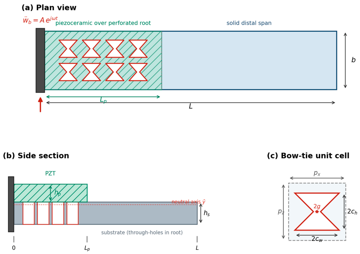
In this work, we address both gaps with a perforated-root piezoelectric cantilever in which a doubly periodic array of bow-tie (double-arrowhead) through-slits occupies the high-curvature root region directly beneath the piezoceramic, while the distal span remains solid (
Figure 1). The novelty of the study is threefold. First, and mechanistically, it uses a bow-tie cell whose effective Poisson’s ratio is positive (
Section 2) to show that power enhancement is a substrate-compliance and strain-relocation effect governed by the position of the perforation relative to the electrode and therefore does not require auxeticity. This corroborates and sharpens, with a controlled, root-placed, positive-
configuration, the effective stiffness arguments of Kurt et al. [
32] and Ranjbarzadeh et al. [
30], rather than resolving the debate outright; a single positive-
cell adds one consistent data point but does not by itself isolate compliance from auxeticity. Second, methodologically, it develops a segmented distributed-parameter model in which the perforated root is homogenised and enters the beam through its longitudinal effective modulus
and tests it against three independent finite-element measurements on the explicit hole geometry. A direct axial-tension test of the unit cell returns
against 0.268 predicted (0.7%), and the substrate-only fundamental is 21.7 Hz against 21.5 Hz predicted (1.0%); with the piezoceramic present, however, the reduction predicts 47.7 Hz against an explicit-hole 36.4 Hz. Cell homogenization and the segmented beam are therefore validated, but the absolute frequency of the complete laminated device is not validated and is identified as an open item rather than claimed. Third, and from a design standpoint, it introduces a fatigue-constrained framework in which the net-section ligament stress bounds the usable fill factor, yielding an excitation-dependent optimum and a fill factor–load design map. At equal overall dimensions and piezoceramic, the proposed device delivers about 14% more power than the solid beam at the baseline cell while simultaneously lowering the resonance, with both effects increasing monotonically with hole size.
The remainder of the paper is organised as follows.
Section 2 develops the analytical model the effective properties of the perforated substrate, the reduced piezoelectric coefficient, the segmented composite beam, the coupled electromechanical formulation and the ligament-stress estimate.
Section 3 describes the three-dimensional coupled-field finite-element model.
Section 4 validates the distributed-parameter model against the finite-element results at the fundamental mode.
Section 5 presents the results and discussion the solid-versus-perforated comparison, the effect of hole size, the fatigue-constrained optimisation, load matching and the design map and
Section 6 concludes.
4. Model Validation
The distributed-parameter model was tested against three independent finite-element measurements on the explicit hole geometry, each isolating one link in the chain. Throughout, the baseline cell is case 4 (, ), the eight-hole layout of the device.
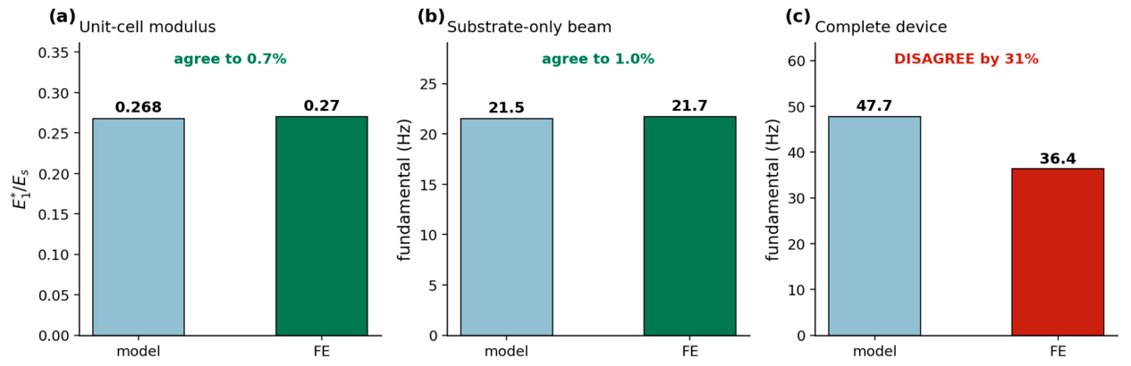
The three checks are summarised in
Figure 6.
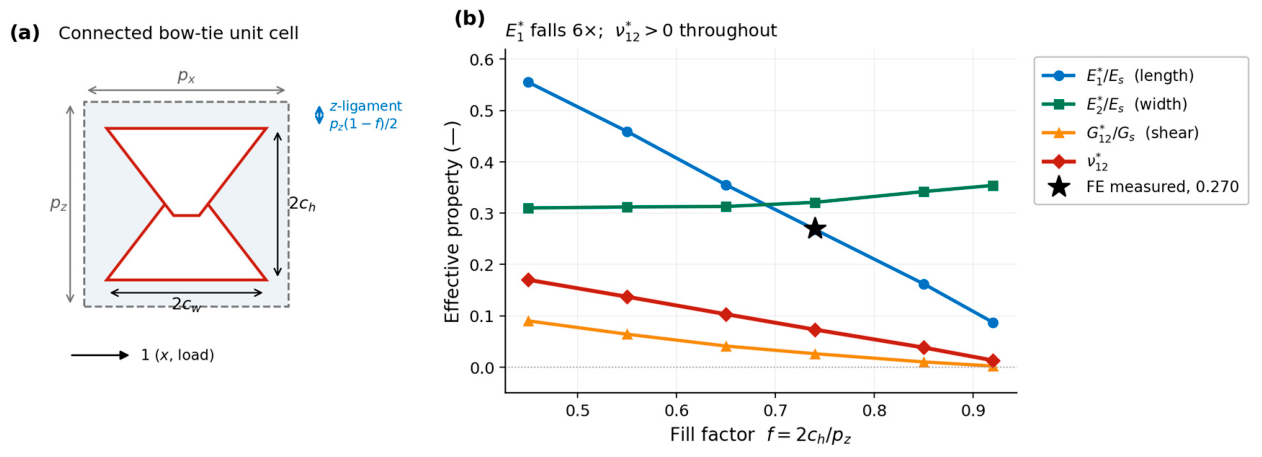
Check 1: the cell. A static axial-tension test on a
-cell strip with free lateral faces (uniaxial stress, 46,625 elements) measured
and
, against 0.634 and 0.268 from the homogenisation: 0.06% and 0.7%. The unit-cell analysis of
Section 2.2 is therefore confirmed directly.
Check 2: the segmented beam. A modal analysis of the substrate alone (no piezoceramic, hence no bonding, no electrical degrees of freedom) returned a fundamental of 21.7 Hz. The four-segment beam of
Section 2 fed the measured
and, honouring the solid margins, predicts 21.5 Hz: 1.0%. Smearing the perforation over the whole root instead gives 16.4 Hz, in error by 24%; the margins, not the beam theory, account for that difference.
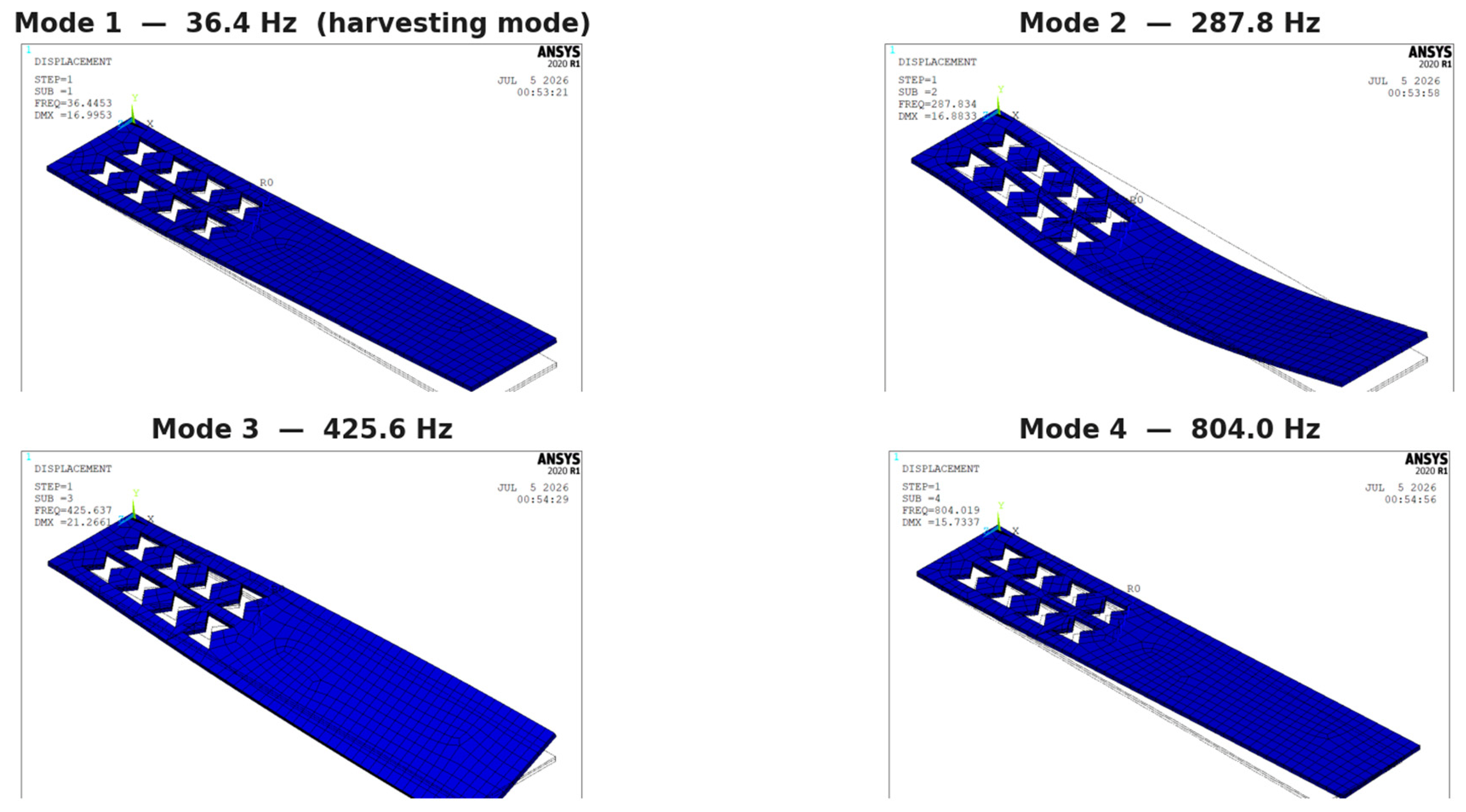
Check 3: the complete device. With the piezoceramic present, the same reduction predicts a short-circuit fundamental of 47.7 Hz, whereas the explicit-hole coupled-field model returns 36.4 Hz. The piezoceramic raises the measured fundamental by a factor of 1.68 () but the model by 2.22 () the beam gains more stiffness from the patch than the three-dimensional model does. Two mechanisms are candidates and the present results do not separate them. The finite-element model bonds the patch by merging coincident nodes, and the two meshes are not conformal at the interface–the substrate face is perforated and refined, the patch face solid and coarse–so the patch may be only partially engaged and the measured frequency correspondingly soft. Equally, the beam treats the root as a perfect two-layer laminate, whereas the holes are several millimetres across on a 0.5 mm substrate: above a hole there is no substrate at all, and composite action is lost locally in a way the laminate assumption cannot represent. Therefore, we treat 47.7 and 36.4 Hz as two unresolved model predictions rather than as bounds on a physical value, since neither model is independently known to over- or under-predict. A useful additional observation is that the explicit-hole 36.4 Hz is a short-circuit modal result, in which electromechanical stiffening is negligible; it is therefore effectively the elastic frequency of the substrate-piezoceramic laminate. The analytical 47.7 Hz is likewise a purely elastic composite prediction, its eigenvalue containing no electromechanical term. The discrepancy is therefore mechanical, not electromechanical, and the piezoelectric coupling can be ruled out as its cause.
We therefore report on the position plainly. The cell homogenization and the segmented beam are validated to about 1%. The absolute harvesting frequency of the complete laminated device is not: it lies somewhere between 36 and 48 Hz, and settling it requires a coupled-field model with conformal substrate–piezoceramic bonding. The trends reported in
Section 5: the direction and relative magnitude of the power gain and frequency shift with hole size rest on the two validated links and are not affected by this open item, but absolute frequencies should be read with it in mind. We emphasise that the power comparisons rest on the two validated links: the +14% gain is a ratio evaluated at each device’s own resonance under the same base acceleration, and both the effective modulus (0.7%) and the substrate-only fundamental (1.0%) are confirmed by finite element. The unresolved 31% concerns the absolute resonance of the complete laminate, which shifts where the peak sits but not the mechanism or the relative trends; a coupled-field model with conformal bonding is the specific step that will resolve it and is ongoing.
5. Results and Discussion
Unless stated otherwise, the excitation is 1 m s−2 (), the load is and . Every comparison holds the beam length, width, thickness, piezoceramic patch and materials fixed, so that only the substrate topology differs.
5.1. Solid Versus Perforated-Root Harvester
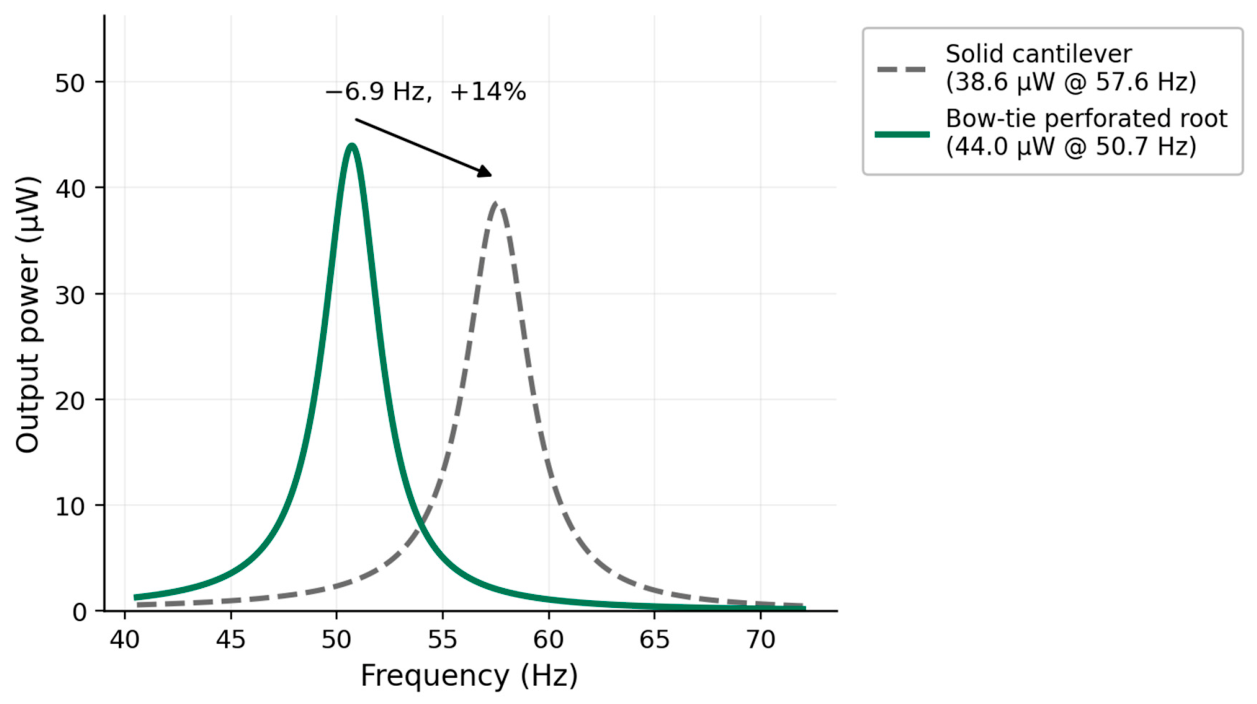
Figure 7 compares the plain solid cantilever with the bow-tie harvester in which the perforation lies in the root, beneath the electrode. The perforated-root device delivers a higher peak power, 44.0 μW against 38.6 μW for the solid beam (a gain of 14% at equal overall dimensions and piezoceramic), and its resonance falls from 57.6 to 50.7 Hz. The response therefore shifts both upward in power and toward lower frequency. The perforated device is lighter than the solid beam by about 37% of the substrate mass over the perforated band; this mass removal is part of the mechanism and is discussed below. Each device is compared at its own resonance under a flat 1 m s
−2 base excitation; because ambient spectra are not flat, the delivered advantage under a specific vibration spectrum will differ from the resonant comparison quoted here.
Observation. The gain originates from a substrate-compliance strain-amplification mechanism. Perforating a span removes both mass and stiffness: the stiffness reduction increases the local bending curvature and hence the strain, while the mass reduction lowers the inertial forcing. In a cantilever, the curvature is greatest near the clamp, exactly where the piezoceramic is bonded; placing the compliant cells there amplifies the strain delivered to the transducer, whereas the mass removed near the clamp contributes little to the modal forcing because the mode-shape amplitude is small there. The strain gain therefore outweighs the mass penalty and the net power rises, while the reduced root rigidity lowers the resonance. The effect is governed by the position of the perforation relative to the electrode, not by the perforation itself.
5.2. Effect of Hole Size
The hole size, parametrized by the fill factor
, sets the effective substrate modulus
and the relative density
.
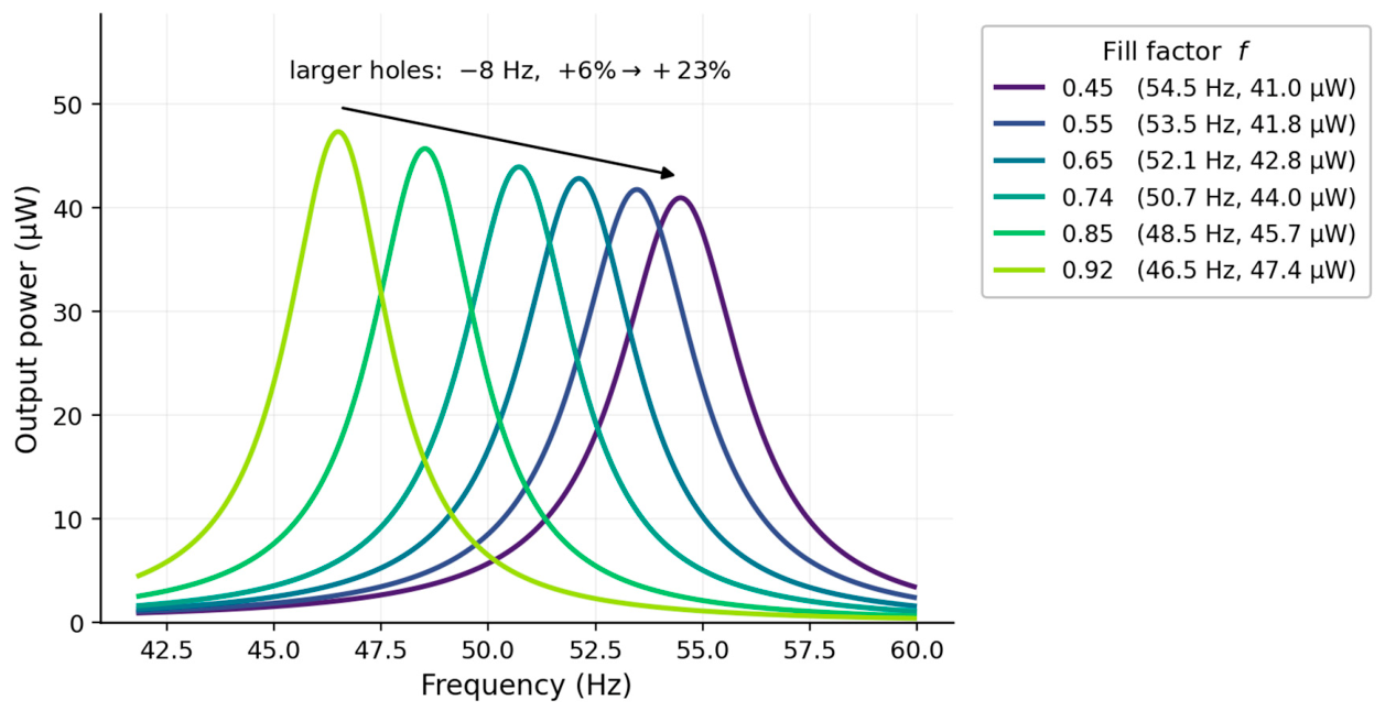
Figure 8 and
Table 5 show the power response for six cell sizes. As the holes grow, the peak power rises monotonically from 41.0 to 47.4 μW (6 to 23% over the solid beam) while the resonance falls from 54.5 to 46.5 Hz, a shift of 11 Hz without any added mass.
It is worth being explicit about why must be the width fraction. Had the hole instead been enlarged along the beam axis at fixed , the effective modulus would have moved only from 0.314 to 0.260: the resonance would have shifted by under 1 Hz and the peak powers would have differed by 0.4%, i.e., the sweep would have shown nothing. The load path is pinched by the ligaments, not by the extent of the hole along and only a fill factor defined on the width exposes the design freedom.
Observation. Both directions are favourable for vibration harvesting. The rising power follows directly from the strain-amplification mechanism; the falling resonance is an independent benefit, because ambient mechanical vibration is concentrated at low frequency (10–100 Hz). A same-size solid beam is often too stiff to resonate in this band without an added tip mass, whereas increasing the cell size tunes the device downward without any mass addition. The design thus offers a single geometric parameter that simultaneously increases the power and lowers the operating frequency.
5.3. Fatigue-Constrained Optimisation
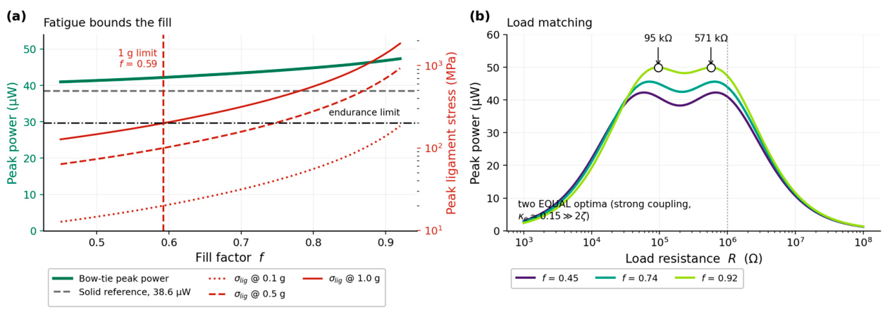
The power gain cannot be increased without bound, because softening the root also raises the stress in the slender ligaments.
Figure 9a plots the peak power against fill factor together with the ligament stress at three excitation levels; the stress grows steeply with hole size, so the practical limit is set by the substrate endurance strength rather than by power. The bound here is a net-section scaling argument: Equation (10) magnifies the beam-surface strain by
and the concentration factor
. The three-dimensional stress field of
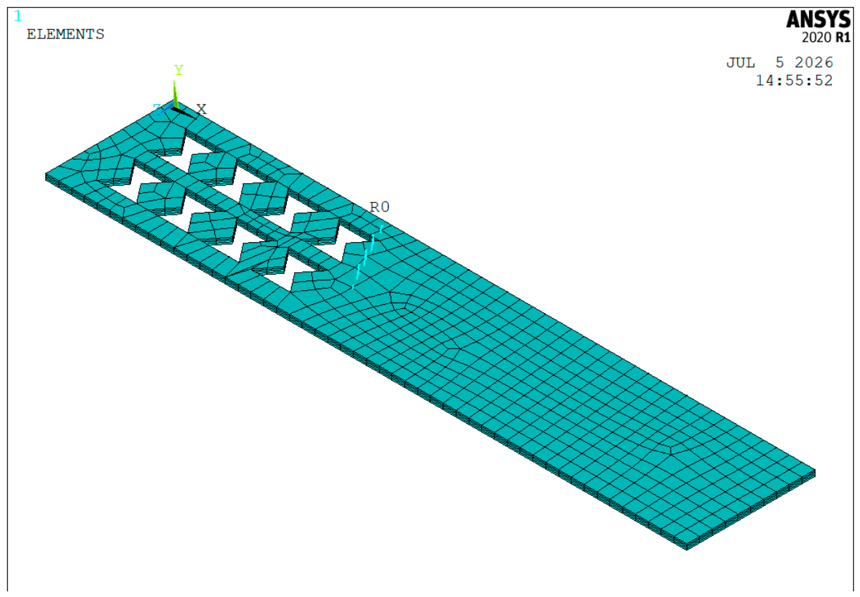
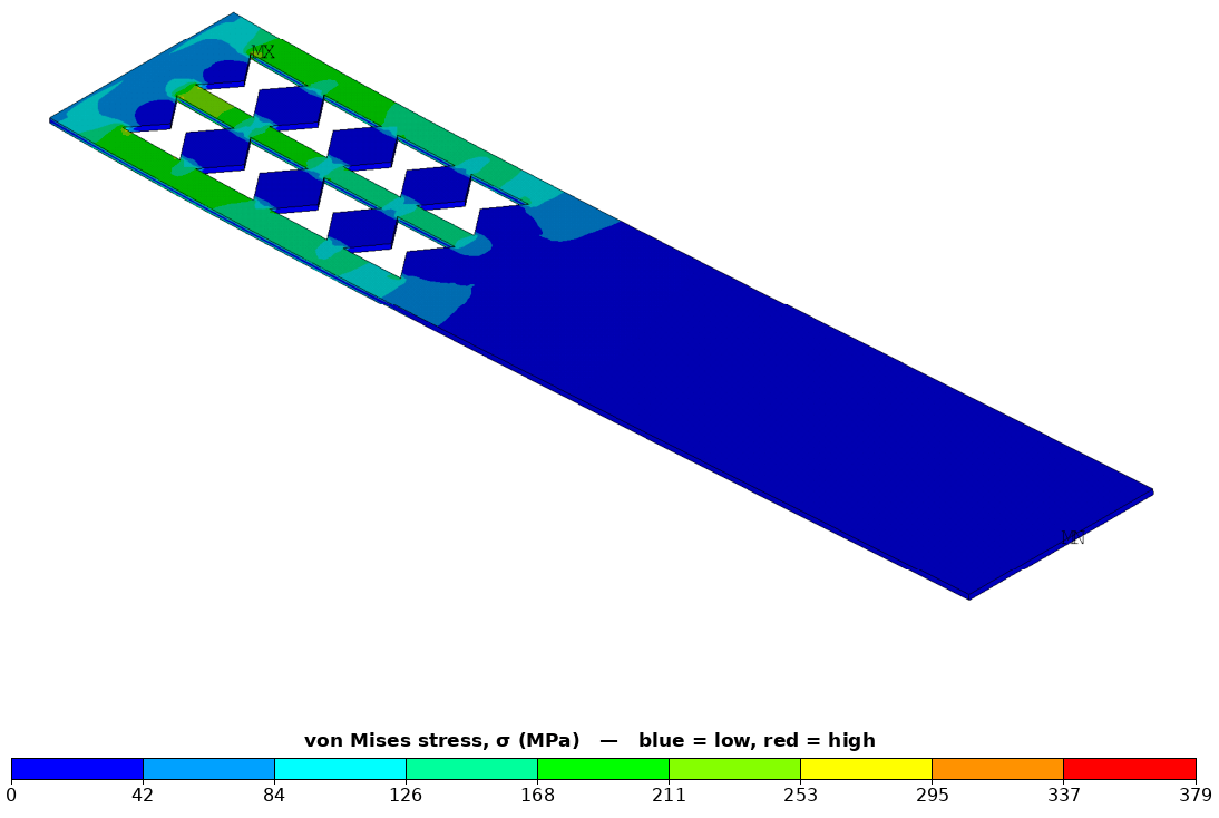
Figure 5 is a harmonic solution at 1 g on the explicit geometry; it confirms both the location of the critical stress (the inter-slit ligaments, as Equation (10) assumes) and its order of magnitude, with a peak of 379 MPa. A ligament-refined mesh with a peak-stress convergence check would sharpen the fillet-dependent value further.
The endurance limit (
at ×10
7 cycles) and stress-concentration factor (
) are representative values for a high-strength metallic substrate; the substrate stiffness and density (
,
) follow the authors’ prior work [
13] and are not tied to a specific named alloy. Because these inputs are representative rather than measured, the fatigue map is presented as an illustrative design trade-off (a scaling argument), not as an FE-confirmed lifetime prediction. The concentration factor (
) is a conservative value for a filleted re-entrant notch (Peterson’s charts), and the endurance limit (
at ×10
7 cycles) is representative of a high-strength metallic substrate; both are stated as representative rather than material-specific. We therefore present the fatigue map explicitly as illustrative of the design trade-off only: it fixes the shape of the power-durability boundary, and the absolute fill limit will move once a specific alloy and its measured S-N data are adopted.
Observation. The optimum is excitation dependent. At 0.1 g, the ligament stress stays below the assumed endurance limit even for the largest cell, so the device is power-limited, and the full gain is accessible. Because the stress scales linearly with acceleration, at 1 g the same cells reach the limit, and the design becomes fatigue-limited: the largest usable fill falls to . The optimal cell size is therefore application-specific, and a harvester intended for high-acceleration environments must trade some of the available power for durability. This constrained optimum, rather than a monotonic sweep, is the design-relevant result.
5.4. Load Matching and Design Map
Figure 9b shows that each cell exhibits a power maximum near
, below the 1 MΩ used elsewhere; matching the load raises the harvested power for every size, and
is only weakly dependent on the perforation because
is set by the (unchanged) piezoceramic. Combining the two design variables,
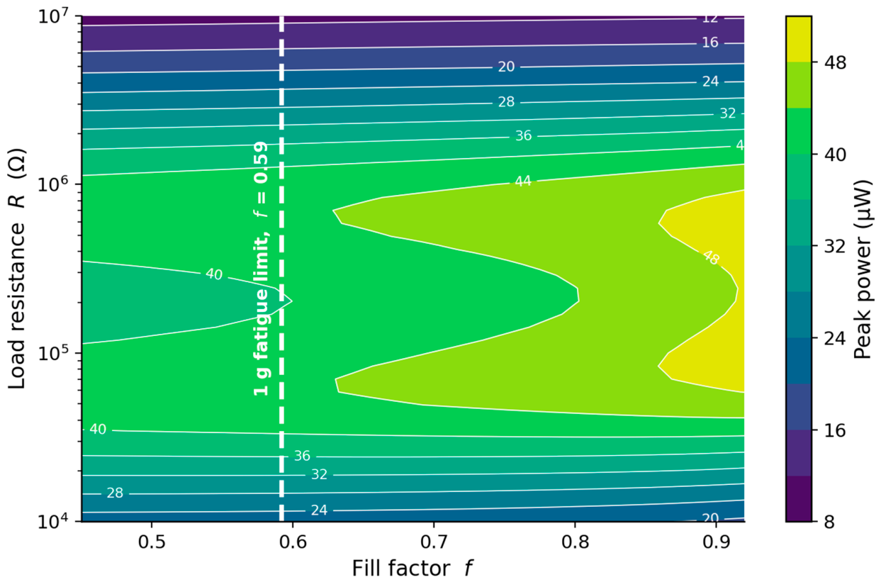
Figure 10 presents the peak power over the fill factor–load plane with the fatigue boundary overlaid, identifying the operating region that maximises power within the durability constraint: large cells operated near
but inside the fatigue limit.
The load curves deserve a comment. This harvester is strongly coupled: the dimensionless coupling exceeds by nearly a factor of four. Each cell therefore shows two power maxima rather than one near 72 kΩ and 641 kΩ, on the short- and open-circuit branches, respectively and the two are equal to four decimal places. The familiar weak-coupling estimate does not apply, and reporting a single matched load would be arbitrary: either branch delivers the same power, and the choice between them is a circuit design question, not a harvester one. The weak-coupling estimate is therefore not an optimum for this device; it lies in the dip between two equal branches, and we do not equate it to a matched load.
5.5. Discussion
The results establish a transparent design principle for cellular substrate piezoelectric harvesters: the perforation should occupy the high-curvature region beneath the electrode, where reducing the substrate stiffness amplifies the strain delivered to the transducer, so that the device simultaneously gains power and shifts to a lower, more useful resonance. Three further points follow.
First, the enhancement is a compliance and strain-relocation effect and is distinct from a negative Poisson ratio (auxetic) mechanism; the present cell exhibits a positive effective Poisson ratio (
Section 2), so the benefit here arises from compliance rather than auxeticity. This corroborates and sharpens the effective stiffness arguments of Kurt et al. [
28] and Ranjbarzadeh et al. [
34]: the root-placed, positive-
configuration adds one controlled data point but does not by itself isolate compliance from auxeticity, which would require a matched-compliance comparison of a positive-
and a negative-
cell at equal effective bending stiffness. That comparison is a clear next step; the present contribution is the placement principle and the fatigue-constrained design that follows from it. Two design questions follow. Because the mechanism is compliance-driven and shape-agnostic, round holes or slots at matched modulus would give the same gain; the bow-tie was chosen as the canonical auxetic motif to make the mechanistic point, and a round-hole comparison is a natural simplification. A bimorph would centre the neutral axis by symmetry, remove the perforation-induced lever-arm reduction and roughly double the active material, in a natural higher-output extension.
Second, the effective bending behaviour of the perforated root and hence the absolute resonance is governed by the cell’s effective stiffness rather than by its area fraction alone: at
the cell retains 63% of its area but only 27% of its longitudinal modulus. Two bookkeeping points proved decisive and are worth stating for anyone repeating this class of analysis. The fill factor must be defined on the dimension that pinches the load path; defined on the beam axis instead, the entire sweep collapses and the design freedom disappears. And the perforation must be applied to the area it occupies: the solid margins around the hole array carry load, and smearing the homogenised modulus over the whole root under-predicts the fundamental by 24%. With both handled, the segmented beam matches an explicit-hole substrate model to 1%. The laminated device remains the open case (
Section 4).
Third, the harvested power is sensitive to load matching, so performance should be reported at rather than at an arbitrary load, and the achievable hole size is bounded by ligament fatigue and therefore by the target excitation amplitude.
The study has limitations that also define the next steps. The distributed model is one-dimensional and assumes full strain transfer to the piezoceramic, so the reported power is an upper estimate; the ligament stress is a nominal net-section value whose fillet-dependent peak requires a resolved three-dimensional notch analysis; and the endurance limit and stress-concentration factor are representative rather than material-specific. An experimental demonstration on a laser-cut substrate would provide the strongest confirmation of the predicted power gain and frequency shift, and a spatially graded perforation denser near the clamp where the curvature peaks is a natural extension of the present framework.
6. Conclusions
This study introduced a perforated-root piezoelectric cantilever harvester in which a doubly periodic bow-tie cellular array occupies the high-curvature region of the substrate directly beneath the piezoceramic and developed the distributed-parameter and finite-element models required to design it. Three conclusions follow.
First, power enhancement is a compliance effect rather than an auxetic one. Because the chosen bow-tie cell has a positive effective Poisson’s ratio, the gain observed here cannot be ascribed to a negative Poisson’s ratio; it arises because softening the substrate in the high-curvature root amplifies the strain delivered to the transducer, while the mass removed there contributes little to the modal forcing because the mode-shape amplitude is small near the clamp. The enhancement is therefore governed by the position of the perforation relative to the electrode. Because the chosen cell has a positive effective Poisson’s ratio, this result corroborates and sharpens the effective stiffness arguments of the cellular substrate literature [
28,
30] rather than resolving the auxeticity debate outright, which would require a matched-compliance positive-versus-negative-
comparison.
Second, the segmented distributed-parameter model with the perforated root homogenised and entering the beam through its longitudinal effective modulus and the piezoelectric coupling reduced to its plane-stress value was tested against three independent finite-element measurements on the explicit hole geometry. Two confirm it: an axial-tension test of the unit cell gives against 0.268 predicted (0.7%), and the substrate-only fundamental is 21.7 Hz against 21.5 Hz predicted (1.0%). The third does not: with the piezoceramic present, the reduction predicts 47.7 Hz against 36.4 Hz. The cell homogenisation and the segmented beam are therefore established; the absolute frequency of the complete laminated device is not and is left as an explicit open item. Either the finite-element bonding of the patch is incomplete, or the perfect-laminate assumption fails where the holes remove the substrate beneath it; a coupled-field model with conformal bonding is required to decide, and until then only the trends should be relied upon.
Third, at equal overall dimensions and piezoceramic, the perforated-root device delivers about 14% more power than the solid beam at the baseline cell, 44.0 against 38.6 μW, while shifting its resonance from 57.6 to 50.7 Hz, toward the band where ambient vibration is most intense. Both effects increase monotonically with hole size, reaching 23% and 46.5 Hz at the largest cell examined provided the fill factor is defined on the cell width, the dimension that pinches the load path. Because perforation relocates the peak stress into the slender ligaments, the usable hole size is bounded by ligament fatigue: under a 1 g constraint, the largest usable fill is , and a harmonic finite-element solve on the explicit geometry returns 379 MPa at the baseline cell-confirming the location and order of magnitude of the net-section estimate, and placing the device as built outside its own durability bound. Because the harvester is strongly coupled (), the load curve has two equal optima rather than one, near 72 kΩ and 641 kΩ, so performance should be reported at a stated branch within the fatigue limit rather than at an arbitrary resistance.
Several extensions follow naturally. The distributed model is one-dimensional and assumes full strain transfer to the piezoceramic, so the reported power is an upper estimate; a resolved three-dimensional notch analysis would sharpen the fillet-dependent ligament stress, and an experimental demonstration on a laser-cut substrate would provide the strongest confirmation of the predicted power gain and frequency shift. A spatially graded perforation denser near the clamp where the curvature peaks is a promising route to further gains within the same fatigue budget.