2.1. Saturation Characteristic Analysis and Modeling Requirements
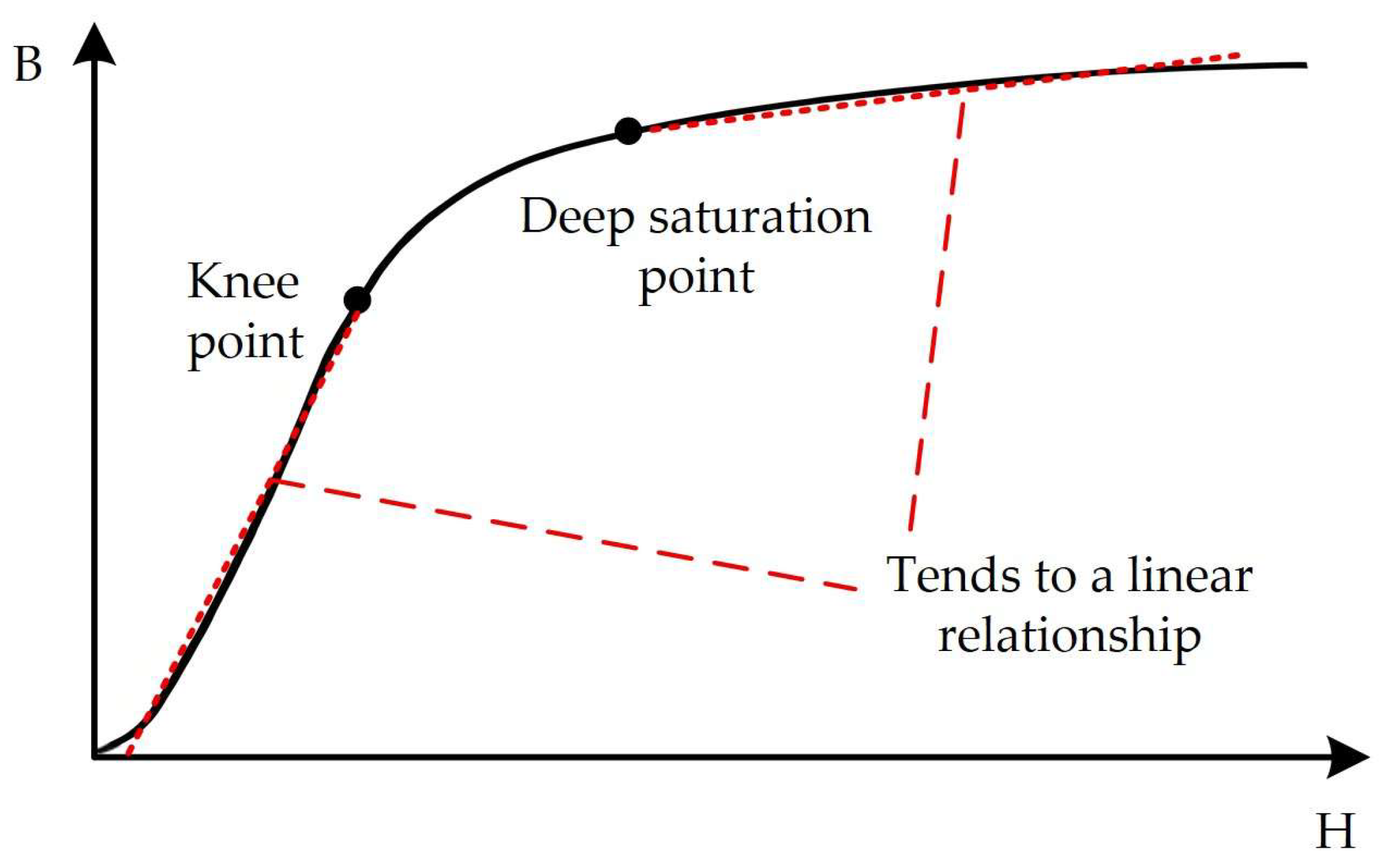
The core of a hybrid excitation generator is made of soft magnetic materials such as silicon steel sheets. Its B-H curve, shown in
Figure 1, exhibits typical nonlinear characteristics: the flux density increases approximately linearly in the low magnetic field strength region; as the field strength increases, the permeability gradually decreases, and the flux density growth slows down after the material enters the saturation region.
The uniqueness of the hybrid excitation generator lies in the fact that the magnetic field is established jointly by the permanent magnets and the field winding, and the operating point of the magnetic circuit is affected by both the field current and the armature current. The magnetomotive forces generated by the two sources superimpose, causing the core saturation level to vary dynamically with operating conditions, resulting in a strongly nonlinear coupling relationship between flux linkage and current.
The above saturation nonlinearity is directly reflected in the flux linkage–current characteristics. In the low-current region, the flux linkage increases approximately linearly. As the current increases, the growth rate of the flux linkage gradually slows down, and the increment becomes extremely limited in the deep saturation region. Under different combinations of field current and armature current, both the saturation knee point and the asymptotic value of the curve family shift. This characteristic makes traditional linear models with fixed slopes produce significant errors in the saturation region, while piecewise linearization or simple polynomial fitting fails to provide a smooth and continuous description over the entire operating range. Therefore, an explicit nonlinear model that can uniformly describe the complete flux linkage characteristics from the linear region to the deep saturation region, and is concise in form, is required.
2.2. HEG System and Basic Equations
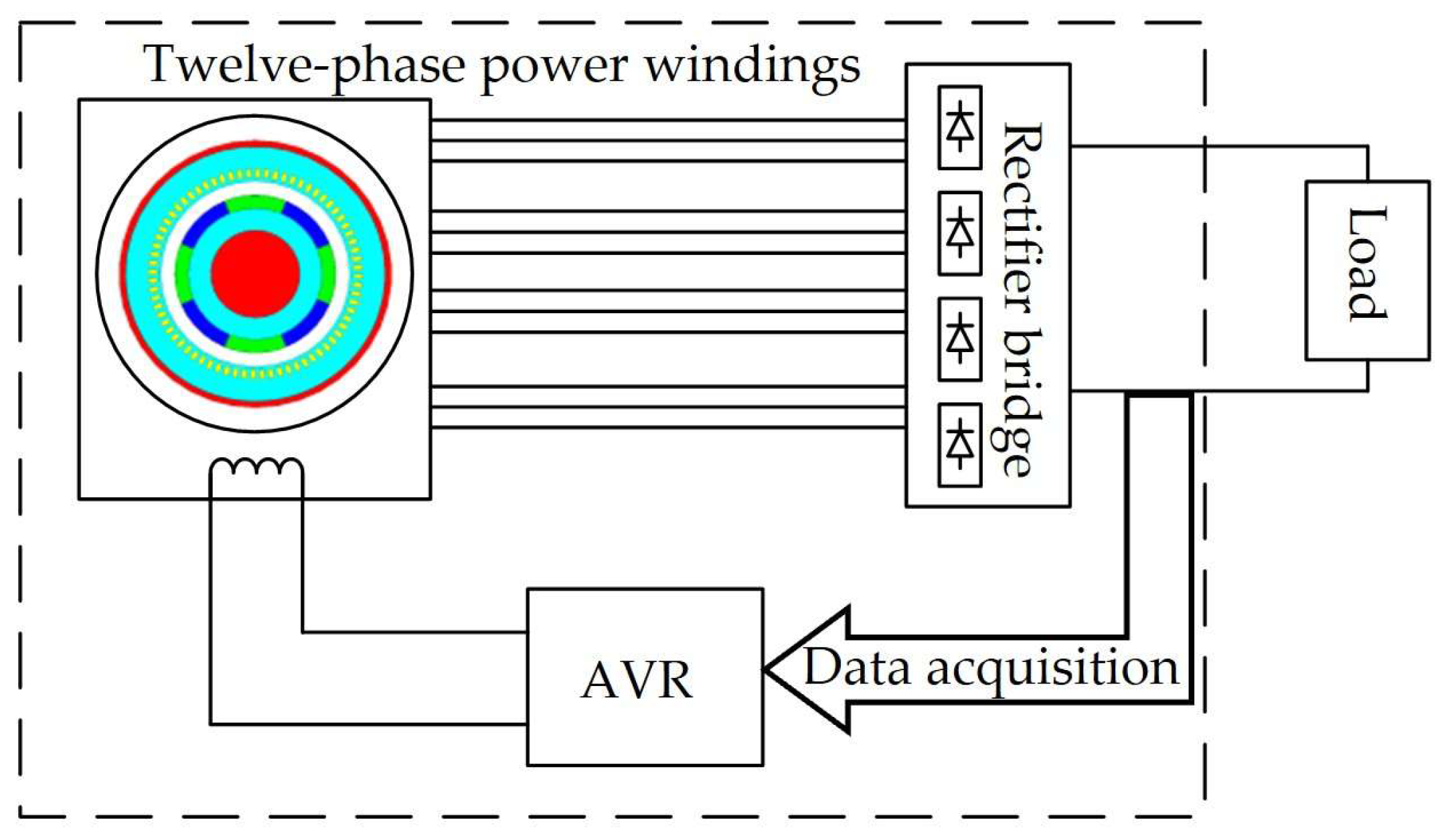
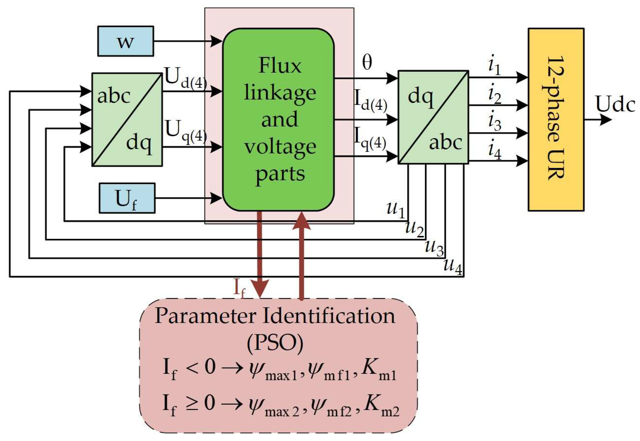
The block diagram of the HEG system is shown in
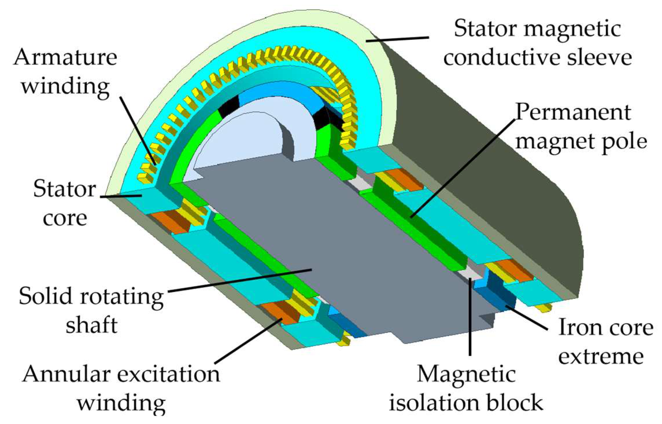
Figure 2, and the topology diagram of the twelve-phase hybrid excitation generator is shown in
Figure 3.
Among them, an AVR (Automatic Voltage Regulator) is an automatic excitation control device that maintains the terminal voltage of a synchronous generator at a prescribed level by regulating the field current in response to grid disturbances or load variations. The hybrid excitation generator model is established in the d-q rotating coordinate system, and the flux linkage equations and voltage equations of the generator can be expressed as Equations (1) and (2), respectively:
where
ψdq is the stator and rotor flux linkage column vector;
udq is the stator and rotor voltage column vector;
idq is the stator and rotor current column vector;
Rdq is the stator and rotor resistance matrix;
ωs is the electrical angular speed of the generator;
Ldq is the stator and rotor inductance matrix; and
G is the sign matrix [
25].
ψpmd = [ψpmd0 0 ψpmd0 0 ψpmd0 0 ψpmd0 0 ψpmd0 0 ψpmd0 0]T is the remanent flux linkage column vector; ψpmd0 is the amplitude of the permanent magnet flux linkage, which can be obtained by setting idq to zero. This paper focuses on the nonlinear fitting of the flux linkage equation, and ψpmd0 is assumed to be a known quantity.
2.3. Construction of Nonlinear Fitting Function for Magnetic Saturation
The generator modeling method proposed in this paper mainly considers the influence of the field current of the electrically excited part on the field winding inductance, which in turn affects the overall generator performance. However, to establish a complete model, the stator and rotor inductance matrix
Ldq is processed nonlinearly using a piecewise fitting function to accurately characterize the inductance characteristics of the generator under different saturation levels. Meanwhile, the literature and monograph [
26,
27] provide references for the identification of inductance parameters of the excitation winding and armature winding in this paper, and the monograph [
28] offers references for the measurement methods of other parameters in this paper.
To this end, as shown in Equation (3), the d-q axis resultant air-gap flux linkage
ψm is introduced as the criterion for determining the core saturation level, providing a quantitative benchmark for the subsequent nonlinear correction of the stator and rotor inductance matrix
Ldq.
where
ψdm =
Lad(−
id1 −
id2 −
id3 −
id4 −
ifd −
ikd) and
ψqm =
Laq(−
iq1 −
iq2 −
iq3 −
iq4 −
ifq −
ikq).
ψdm and
ψqm are the d-axis and q-axis air-gap flux linkages, respectively.
id1,
id2,
id3, and
id4 are the currents of the four d-axis stator armature windings, and
iq1,
iq2,
iq3, and
iq4 are the currents of the four q-axis stator armature windings. The armature reaction generated by these currents exhibits a demagnetizing effect. The d- and q-axis field winding currents
ifd and
ifq constitute the magnetizing currents.
ikd and
ikq are the d-axis and q-axis damper winding currents.
To achieve nonlinearization of the stator and rotor inductance matrix
Ldq, the proposed generator modeling method introduces a saturation correction coefficient
Km. The d- and q-axis stator armature reaction inductances
Lad and
Laq, which enter the saturation state, are then corrected using Equations (4) and (5), respectively:
where
Lad0 and
Laq0 are the initial unsaturated d- and q-axis stator armature reaction inductances. As shown in Equation (6), when the equivalent d-q axis flux linkage
ψm exceeds the knee-point flux linkage threshold
ψm1, the generator is determined to be in the saturation state. The specific expression of the saturation correction coefficient
Km is as follows.
Km is a real number between 0 and 1, with a lower limit
Km1 set to approximate the extreme saturation state of the generator. Meanwhile, a quadratic-fitting nonlinear operating region—i.e., the transition region between the unsaturated and deeply saturated states—is defined, where
ψm1 <
ψm ≤
ψm2.
In the quadratic-fitting nonlinear operating region, starting from the onset of saturation, the saturation correction coefficient Km gradually decreases from 1 as ψm increases; a smaller coefficient value indicates a deeper saturation level of the generator core. When the equivalent d-q axis flux linkage ψm exceeds the deep saturation point threshold (the upper limit of the nonlinear operating region) ψm2, the saturation correction coefficient Km remains constant at its lower limit Km1.
Taking advantage of the symmetrical characteristic of bidirectional excitation in the hybrid excitation generator, the same flux linkage fitting function form is shared for both positive and negative excitation, thereby simplifying the establishment of the saturation model. Only the identification of different parameter points under forward and reverse excitation is required.
The characteristic curve of ferromagnetic materials is shown in
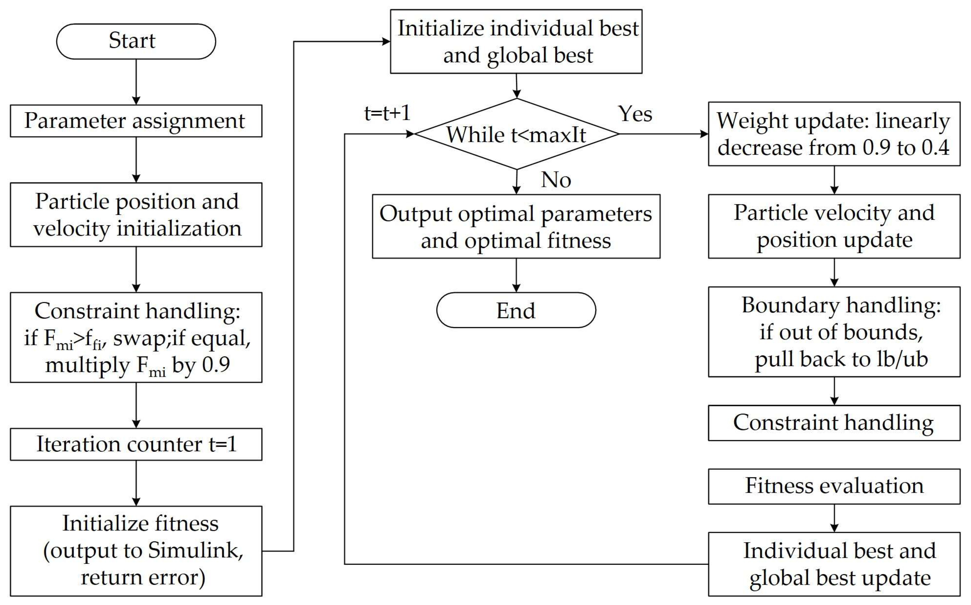
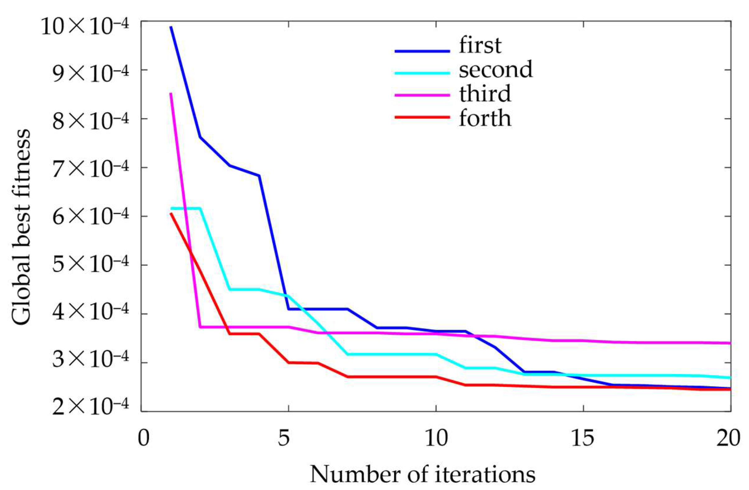
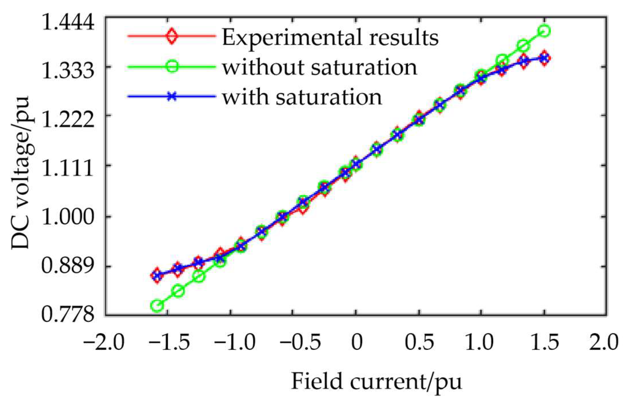
Figure 1. Typically, before the knee point, the B-H relationship can be considered linear. Between the knee point and the saturation point, as the excitation current continues to increase, the output voltage rise rate of the generator slows down significantly, exhibiting nonlinear characteristics. After reaching the deep saturation point, the growth rate becomes extremely slow and can be approximated as a linear increase with a very small slope. The parameters to be identified are listed in
Table 3, where (I) and (II) denote positive and negative excitation currents, respectively.
In summary, by incorporating the saturation correction coefficient Km, which takes different values in different operating stages, into the nonlinear stator and rotor inductance matrix Ldq, a nonlinear description of the generator is achieved.