Review

Sliding Mode Control in Grid-Tied Inverters: Techniques, Applications, and Future Directions

School of Engineering, Edith Cowan University, Joondalup, WA 6030, Australia
*
Author to whom correspondence should be addressed.
Energies 2026, 19(13), 3052; https://doi.org/10.3390/en19133052
Submission received: 19 May 2026 / Revised: 19 June 2026 / Accepted: 26 June 2026 / Published: 28 June 2026
(This article belongs to the Section A: Sustainable Energy)

Abstract

Sliding mode control (SMC) has emerged as a robust and adaptive strategy for grid-tied inverters. It has unique attributes which make it an appropriate control choice under increasingly complex power systems. However, there are a limited number of review articles which comprehensively explore the true potential of SMC for grid-tied inverter applications. This systematic review has been structured to explore SMC techniques with respect to certain challenges, i.e., stability challenges, unbalanced conditions, low inertia scenarios, and harmonics distortion. The classification of various SMC techniques is presented with respect to their control law and sliding surfaces design. The comparative analysis indicates the dominance of artificial intelligence (AI)-assisted control systems, which represent a paradigm shift in modern-era control systems. Key performance matrices, i.e., total harmonics distortion (THD) reduction, tracking accuracy, and response time, etc. are compared across various SMC techniques. Moreover, this review identifies possible research gaps regarding the conceptual integration of quantum computing with SMC. Furthermore, several future directions are presented in this article to make SMC more robust and reliable for the next generation of AI-dominated grid-tied inverter applications.

1. Introduction

In recent years, the ambition to achieve net zero has invoked the global deployment of inverter-based resources (IBR), i.e., hybrid micro grids, battery energy storage systems (BESS), and photovoltaic (PV) systems [1]. However, this requires some compromises on the electric grid which lead to challenges associated with power system stability. The integration of IBRs significantly reduces grid inertia, which makes it vulnerable in terms of frequency stability [2]. Hence, it is essential to develop advanced control strategies capable of maintaining grid stability and power quality. In modern grids, ensuring the robustness and adaptive control of inverters has assumed vital significance for overcoming such stability vulnerabilities. Several challenges related to low inertia, under-frequency load shedding (UFLS), and grid uncertainties have emerged as a result of IBRs integration [3]. In conventional power systems, synchronous generators inherently provide inertia support and voltage regulation. In contrast, IBRs lack these characteristics, which makes them more susceptible to dynamic instabilities. In such scenarios, ensuring reliable power delivery and resilient system operation under varying load conditions becomes critical. This can be achieved by integrating robust control strategies into existing IBR networks. In this regard, SMC offers a versatile solution due to its unique properties [4]. Its invariance properties are responsible for optimal operational performance during uncertainties [5]. It can contribute to an optimal mechanism for power sharing, sufficient grid support, and strengthened system operation in islanded or weak-grid scenarios [6]. Grid-forming (GFM) and grid-following (GFL) inverters are required to comply with grid standards and ensure high-quality power delivery in terms of fault ride-through (FRT) capability and harmonic limitations. In this context, the robustness and fast dynamic response of SMC make it a promising control strategy for such applications.
Recently, there has been a significant increase in the deployment of IBRs in distribution networks [7]. These networks usually have a low short-circuit ratio (SCR), voltage sags, asymmetric faults, high line impedance, and unevenly distributed loads [8]. These factors contribute to reduced stability for grid-tied inverters during severe transient events and harmonic distortion. As a result, the complexity of the systems is enhanced. During such uncertainties, traditional linear controllers, i.e., PI or PR, become vulnerable due to their lower dynamic response, limited control over parametric challenges, and insufficient disturbance rejection [9]. Moreover, several resonant dynamics are introduced to the system by LCL filters. As a result, a Proportional–Integral (PI) loop often requires a multi-resonant compensator and strict gain tuning. The presence of unbalanced conditions in the power network introduces complexities in power injection and complicates the overall control process. Moreover, control limitations and resonance in LCL filters increase tracking errors, resulting in further stability challenges for grid operation [10]. While other advanced methods, i.e., Model Predictive Control (MPC) or H can offer high performance, they can introduce significant computational complexity or sensitivity to model inaccuracies. This renforces the need for robust control strategies to cope with these vulnerabilities for reliable power system operation.
In grid-tied inverters, SMC has proven to be a robust and flexible technique [11]. The operation of SMC relies on the design of the sliding surfaces, which enable high resilience and finite-time convergence under balanced and unbalanced grid conditions. However, conventional SMC employs fixed tuning parameters and is largely model dependent. Recent research has therefore focused on optimizing these parameters using AI-based techniques, i.e., deep learning and other data-driven approaches. Furthermore, SMC-based control techniques exhibit a more robust response when connected with nonlinear loads and fast-switching power converters [12,13,14]. More advanced variants of SMC, i.e., super-twisting and decoupled average model-based controllers, significantly reduce the chattering effect and provide smooth convergence to ensure effective control and resilient operation of power systems [15,16]. To implement SMC in grid-tied inverter applications, several requirements such as boundary layers and state observers must align with saturation strategies. The adaptive tuning and AI-based gain tuning of higher-order SMC techniques support robust current and voltage tracking for GFM and GFL inverters. These characteristics make SMC a suitable control strategy in IBR networks to provide voltage regulation, current injection, and stability under balanced and unbalanced grid scenarios. Moreover, such applications can be validated through hardware setups, e.g., Hardware-in-the-Loop (HIL), DSP, or FPGA platforms.
Various SMC control techniques have been evaluated in the existing literature. However, there remains a lack of systematic reviews on SMC techniques and novel variants. Moreover, existing studies often evaluate algorithmic SMC variants but lack deeper assessments with respect to hardware implementation, hybrid strategies of SMC, application areas, and AI-integrated frameworks, which enable parametric optimisation. This review article presents a comprehensive review of studies on SMC and its variants applied to grid-tied inverter systems, emphasising their control objectives, implementation testbeds, and performance evaluation. A detailed classification of SMC control objectives is provided, encompassing current control, voltage regulation, disturbance rejection, fault tolerance, harmonic mitigation, and power sharing. Furthermore, control hierarchies in IBRs are examined, particularly under weak-grid and islanded operating conditions. The description of important variables used in the manuscript has been given in the Table 1. The main contributions of the paper are:
  • An application oriented taxonomy is developed to cover conventional, higher-order, adaptive, observer-based, intelligent, and hybrid SMC variants.
  • It maps SMC variants to inverter control objectives, including current control, voltage regulation, harmonic suppression, DC-link regulation, MPPT, weak-grid operation, islanding, and fault ride-through.
  • A comparison of different simulation environments, HIL platforms, FPGA/DSP implementations, dSPACE-based prototypes, and laboratory test benches is presented with respect to the SMC taxonomies.
  • It identifies reporting gaps in the literature, especially inconsistent filter specification, limited standard-compliance assessment, incomplete hardware validation, and limited benchmarking against alternative robust controllers.
The review highlights recent advancements in AI-integrated SMC techniques that support the transition toward intelligent and adaptive control systems. The study systematically evaluates existing SMC research through: (a) a taxonomy of conventional, higher-order, observer-based, adaptive, and hybrid variants mapped to grid-tied objectives and standards-aligned power quality (PQ) metrics; (b) an implementation perspective covering discrete-time realisations, saturation handling, and validation methodologies; and (c) a comparative analysis with conventional and advanced control approaches, followed by emerging research directions in SMC-based strategies. Additionally, the article explores a conceptual framework for quantum computing-based SMC control, offering insights into the potential future evolution of this technique. The remainder of the paper is organised as follows: Section 2 provides the review strategy, covering the research article collection and usability. Section 3 explores the SMC foundations and taxonomy for grid-tied inverters. Section 4 covers the range of application areas in grid-tied inverters where SMC has been implemented. A comparative analysis of SMC with other techniques is explored in Section 5. Finally, Section 6 discusses emerging trends and future research directions.

2. Review Strategy

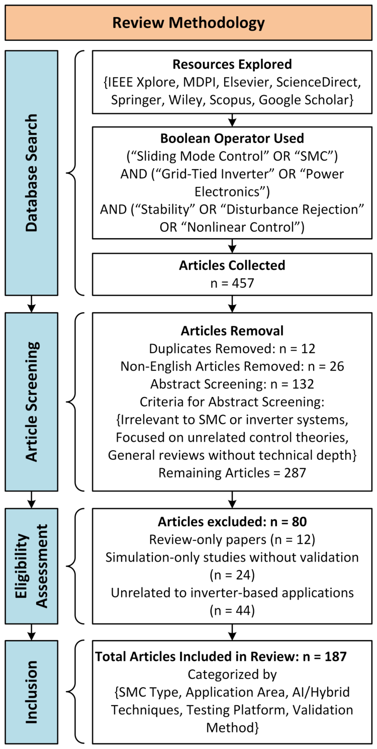
In this review, a systematic approach has been adopted to evaluate the role of SMC in grid-tied inverter applications with respect to different perspectives, i.e., weak grids scenarios, voltage and current control, and FRT. The PRISMA-2020 statement and flow diagram for systematic review was adopted to carry out this review [17,18]. The modified flow diagram adopted for this work is presented in Figure 1. Major scholarly repositories, i.e., IEEE Xplore, ScienceDirect, Wiley, SpringerLink, and Google Scholar were queried over the time span covering major developments in SMC technology for grid-connected inverters. The combination of Boolean expressions, i.e., (sliding mode control OR SMC) AND (SMC for grid-tied inverter OR SMC for power electronics) AND (power system stability OR disturbance rejection OR nonlinear control) was used to collect n = 457 articles. Once these articles were collected and classified as per the domains, then the second phase was article screening. We removed 12 duplicates and 26 non-English articles before proceeding towards further analysis. However, 132 articles were excluded at the next stage due to their irrelevance to the review focus. As a result, 287 articles cleared the eligibility assessment and were further explored for inclusion in this review. Full-text assessment then excluded 80 studies for the specific reasons that are indicated in Figure 1. In the final stage, a total of 187 studies were selected from this search. However, some additional studies are cited in this review to support arguments related to the discussed technologies.
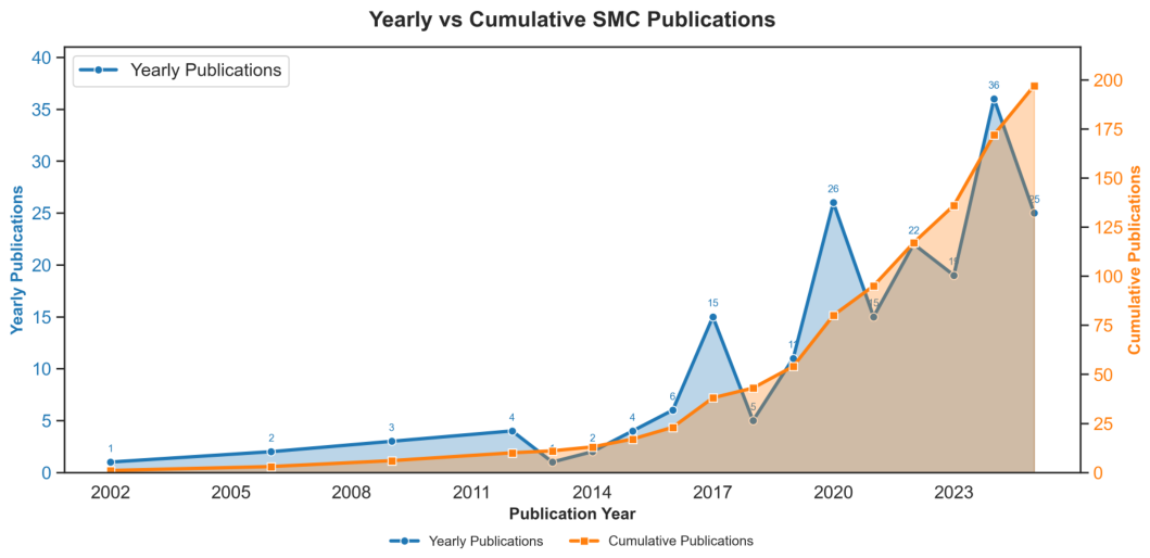
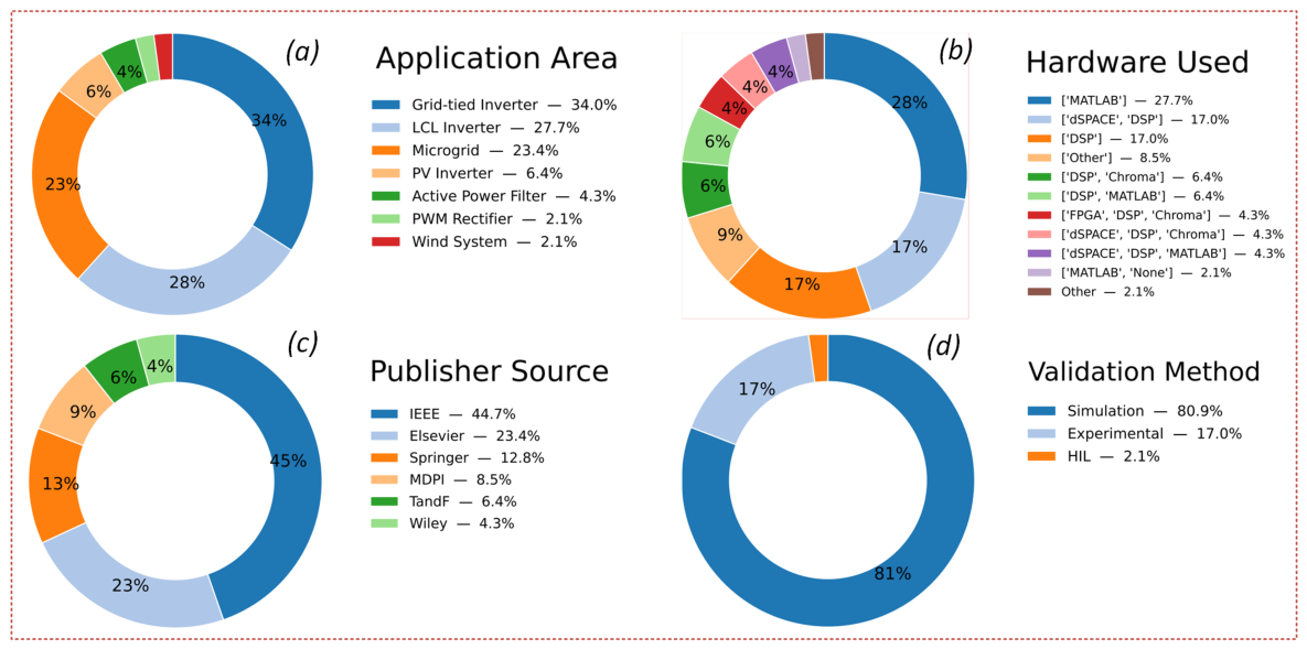
In this review, each study was categorised as per the four classification categories and these areas were then processed through Jupyter Notebook (version 7.4.5) to perform data analysis using Pandas, which resulted in the analysis to check yearly publication trends and classification of studies for better understanding. The classification was based on (i) SMC type (e.g., conventional/first order, higher-order, adaptive, observer-based, and hybrid or intelligent), (ii) application area (e.g., grid-tied inverter, PV inverter, microgrid, LCL inverter, Z-source inverter, active power filter, PWM rectifier, and wind system), (iii) technique (e.g., super-twisting, Lyapunov-based, observer-based, backstepping, PWM-based, linear/PR/PI, and others), and (iv) testing platform (hardware vs. simulation). The temporal trends and other parameters, i.e., publisher, hardware used, application areas, and validation methods were analysed and are presented in Figure 2 and Figure 3. Moreover, the donut charts presented in Figure 3 illustrate the detailed analysis of the significant areas in percentages. This provides a flow of the review article approach based on the aspects being evaluated. To enhance the value of the review article, we compared the key reviews conducted on SMC in different domains. The comparison of these studies is presented in Table 2.

3. Evolution and Taxonomy of SMC in Grid-Tied Inverters

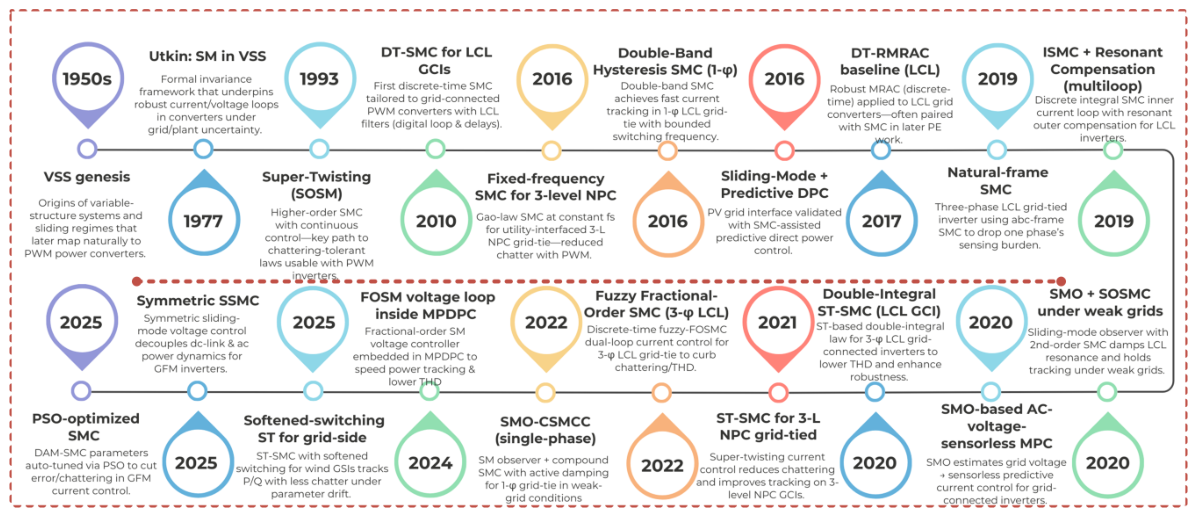
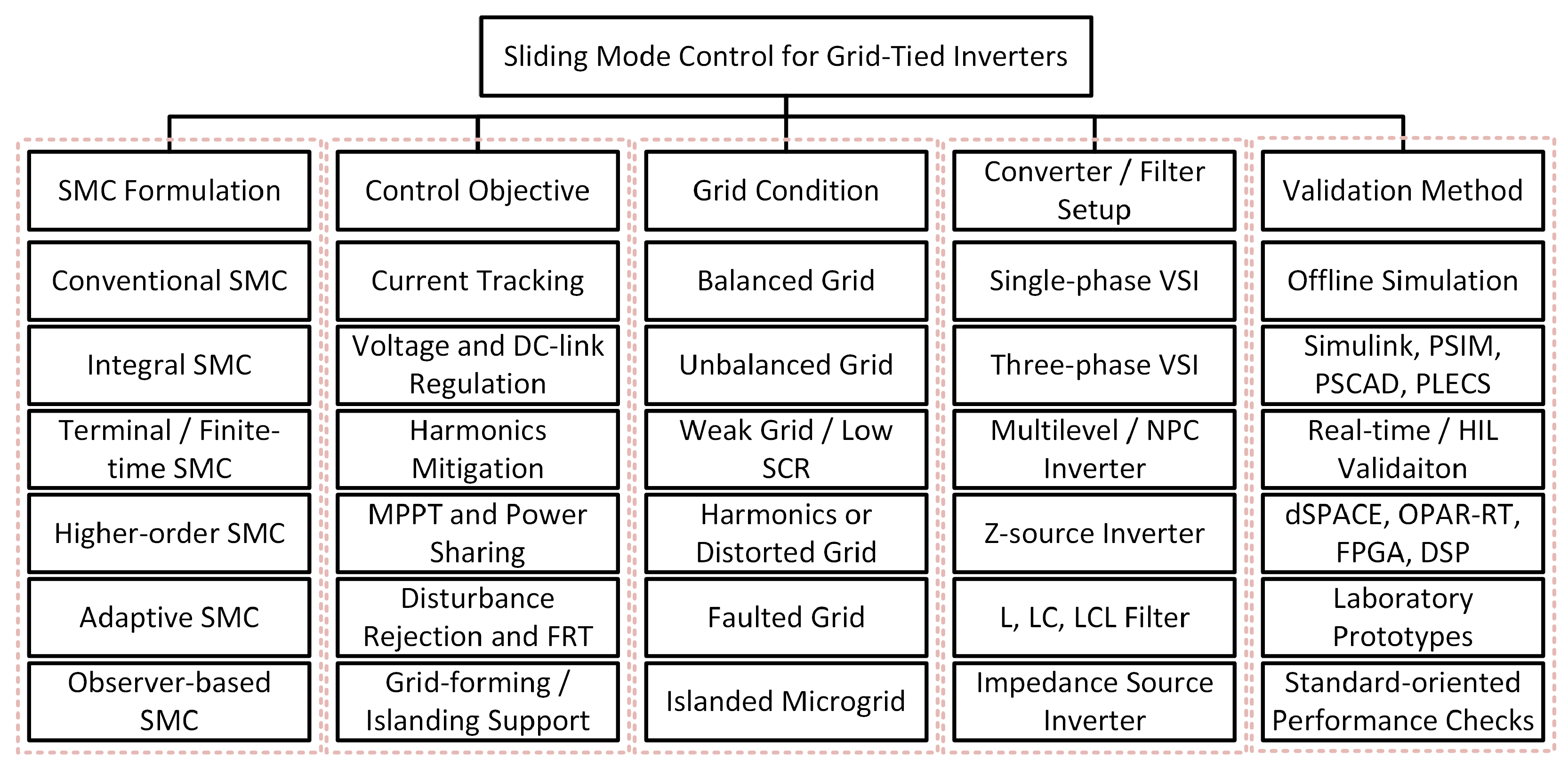
SMC was introduced in 1950 for both linear and nonlinear systems due to its versatile performance and robustness against dynamic uncertainties [21]. The discontinuous control action of SMC is a key element in its operation, which is responsible for pushing system states to achieve optimal points, referred to as sliding surfaces. Moreover, SMC originates from variable structure systems, where it has been explicitly implemented on system dynamics having different architectures depending upon their state trajectories [27]. In the early 2000s, SMC emerged as a promising solution for power electronics applications, i.e., DC-DC converters, etc. [28]. Initially, it was employed on current-mode control systems requiring reliable operation and robustness against demand and supply variations as key features [29]. The evolution of SMC with respect to different variants is illustrated in Figure 4. A taxonomy of SMC for grid-tied inverter applications is provided in Figure 5. The classification is organised according to SMC formulation, control objective, grid condition, converter/filter setup, and validation method.
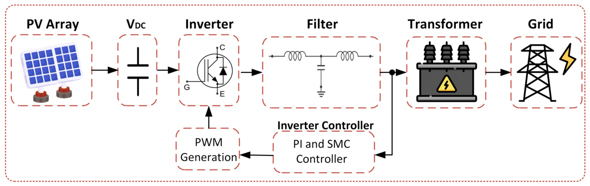
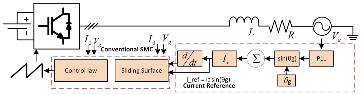
The increasing penetration of renewable energy sources (RESs) significantly enhanced the scalability and complexity of IBRs in modern power systems [30]. Consequently, classical control topologies, i.e., PI and PR controllers became vulnerable, and shortcomings became more obvious. The limitations of conventional control strategies led to egregious performance in unbalanced grid scenarios including limited disturbance rejection and parametric variations [31]. In this regard, SMC evolution from first-order configuration to multiple variants led to a paradigm shift in modern control systems. Furthermore, SMC provides robust and reliable solutions capable of real-time integration, learning, and resilience. Its unique features, i.e., invulnerable operation under uncertainties or external disturbances, make it a key player in grid-connected systems [32]. A simplified version of SMC in a grid-tied environment is presented in Figure 6. SMC has been formulated to serve specific objectives in grid-tied inverters with respect to system configuration and control architecture. These objectives include power optimisation, voltage and current tracking, fault resilience, and harmonics reduction in power systems [27]. Moreover, to achieve these objectives, the control strategy should have a unique sliding surface with optimal tuning strategy and reaching law. SMC control techniques can be classified with respect to control objective, i.e., current control, voltage regulation, MPPT and power sharing, disturbance rejection, fault tolerance, harmonics mitigation, and THD reduction [33,34]. Moreover, SMC has been used for current injection with optimal current tracking in various situations, i.e., load transients, unbalanced grids, and wavering parameters [16].

3.1. Objectives-Based SMC Taxonomies for Grid-Tied Inverters

As discussed in the previous subsection, SMC techniques can be classified with respect to their primary control objectives. Sliding mode control is a robust control technique used to regulate an inverter’s output voltage and current. By continuously adjusting the control input, SMC ensures that the inverter tracks the desired voltage and current references, even under fluctuating grid voltages or varying load demands. This makes SMC particularly effective in maintaining stable and high-quality power delivery despite system uncertainties. In designing inverter controls, the system dynamics and control objectives must be carefully considered prior to implementing both SMC and Phase-Locked Loop (PLL) mechanisms. PLL and SMC are typically coordinated to operate in unison, ensuring that the inverter output is not only accurately controlled but also properly synchronised with the grid voltage. Each objective necessitates a tailored design of sliding surfaces and reaching laws. These classifications are summarised as follows:

3.1.1. Control Objective: Current Control

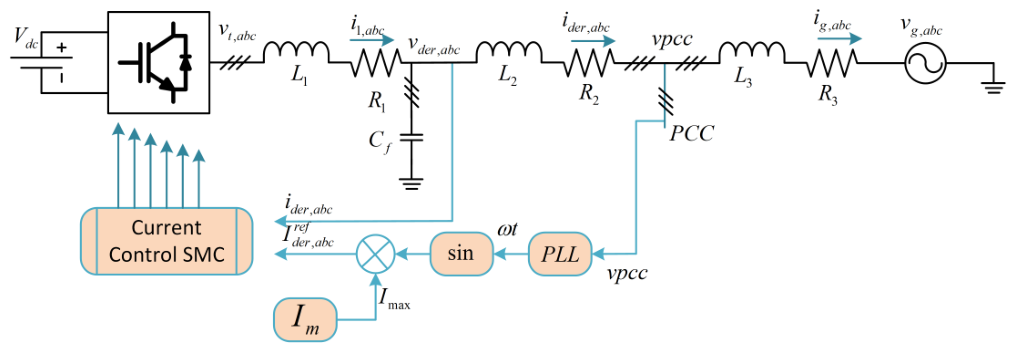
In the context of current control, ref. [36] proposed a sliding surface formulation in the d q -frame. The current tracking sliding surface can be written as
s d q = s d s q = i d , ref i d i q , ref i q
where i d , ref and i q , ref are the reference currents, and i d and i q are the measured or estimated currents in the synchronous d q -frame. Finite-time convergence can then be obtained using a super-twisting SMC reaching law, which is commonly applied in LCL-filter-based voltage-source inverter control. This technique maintained the THD below 2.5%. For these topologies, the corresponding control law is formulated as [37]:
u i = u e q k 1 | s i | 1 / 2 sign ( s i ) k 2 sign ( s i ) d t
where u i is the control input for the i-th control channel, u e q is the equivalent control term, and s i is the sliding variable. The parameters k 1 and k 2 are positive control gains, while sign ( s i ) represents the switching function used to drive the system states toward the sliding surface. A layout of the control structure of SMC for current control is presented in Figure 7. The sliding surface and reaching law can be presented as follows:
σ p = x 3 , p ψ p d t , ψ p = i = 1 3 k i , p x i , p γ i , p sgn x i , p ,
where k i , p > 0 and 0 < γ i , p < 1 .
σ ˙ p = x ˙ 3 , p ψ p ,
v r , p = λ r , p tanh σ p ,
where λ r , p > 0 is chosen according to the worst-case bounds derived from system parameters.

3.1.2. Control Objective: Voltage Control

In [39], a voltage-based SMC was proposed for DC-link voltage regulation, where the sliding surface integrates proportional and integral voltage components. The sliding surface has been defined as
s v = ( V r e f V d c ) + λ ( V r e f V d c ) d t
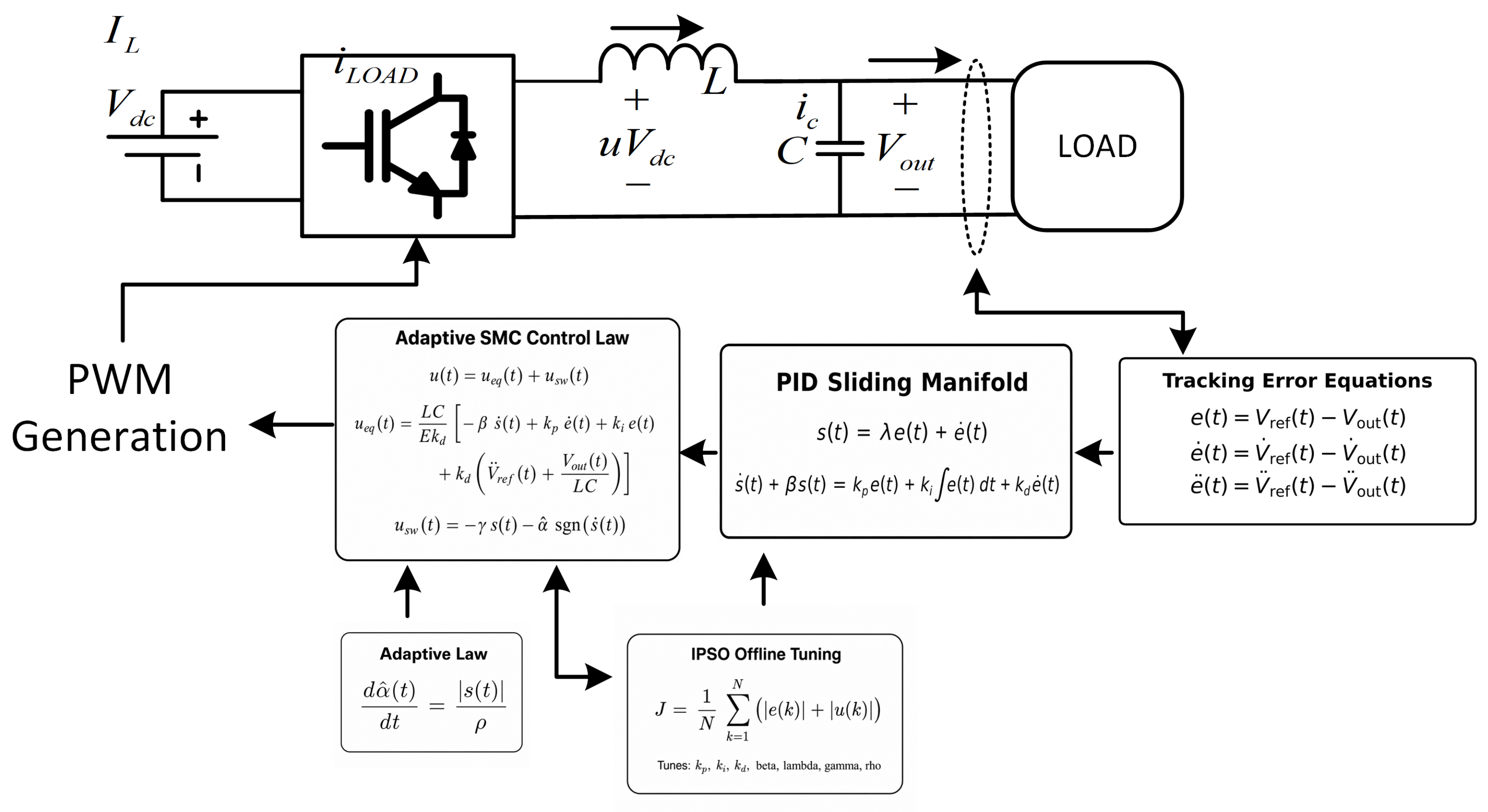
where s v is the voltage-loop sliding surface, V r e f is the reference DC-link voltage, V d c is the measured DC-link voltage, and λ is a positive integral gain. In this, the objective of the integral SMC is to ensure disturbance rejection and attain zero steady-state error. Meanwhile, in [36], a phase-shifted PWM technique was proposed to maintain system stability under 50% load variation. A control structure for voltage-based SMC is presented in Figure 8.
The sliding surface and reaching law for this strategy can be described as:
e ( t ) = v ref ( t ) v o ( t ) , e ˙ ( t ) = d e d t , e ¨ ( t ) = d 2 e d t 2 .
s ( t ) = e ( t ) + α e ˙ ( t ) , α > 0 .
s ˙ ( t ) + η s ( t ) = k p e ( t ) + k i 0 t e ( τ ) d τ + k d e ˙ ( t ) , η , k p , k i , k d > 0 .
u sw ( t ) = κ 1 s ( t ) κ 2 tanh s ˙ ( t ) , κ 1 , κ 2 > 0 .
where e ( t ) is the voltage tracking error, v ref ( t ) is the reference voltage, and v o ( t ) is the output voltage. The terms e ˙ ( t ) and e ¨ ( t ) are the first- and second-derivatives of the tracking error. s ( t ) is the sliding surface, and α is a positive surface coefficient. In the PID-type surface relation, η , k p , k i , and k d are positive tuning gains. The term u sw ( t ) is the switching control component, while κ 1 and κ 2 are positive switching gains used in the reaching law.
However, the method proposed in [39] can uniquely provide voltage recovery using discrete-time mutations during grid sag.

3.1.3. Control Objective: MPPT, Disturbance Rejection, and FRT

SMC techniques have been implemented in PV-dominated systems where maximum power tracking (MPPT) and power sharing are the key objectives. In this scenario, the control objectives are defined based on PV voltage and power, given as d P d V :
s m p p t = d P d V P ( k ) P ( k 1 ) V ( k ) V ( k 1 )
where s m p p t is the MPPT sliding variable, P is the PV output power, and V is the PV voltage. The terms P ( k ) and V ( k ) are the power and voltage at the present sampling instant, while P ( k 1 ) and V ( k 1 ) are their values at the previous sampling instant. For MPPT, SMC control can be integrated with adaptive fuzzy logic [41], Q-learning [42], and CSA-guided STSMC [43], resulting in fast convergence, online tuning, and enhanced tracking efficiency. Similarly, SMC possesses robust performance capacity against grid FRT when disturbance observers are integrated into the sliding surface in an SMC loop. In this scenario, various studies have implemented observer-based SMC which enables smooth operation during faults and voltage sags in balanced and unbalanced grids [15,44,45,46].
d ^ ( t ) = y ( t ) y ^ ( t ) , u = u n o m i n a l d ^ ( t )
where d ^ ( t ) is the estimated disturbance, y ( t ) is the measured system output, and y ^ ( t ) is the observer-estimated output. The term u is the final control input, while u n o m i n a l is the nominal control signal before disturbance compensation. SMC is often used in scenarios where fault-ride-through is required. It provides amplified performance for such scenarios.
Before presenting the mathematical model, the resistance notation is standardised for consistency. In this review, R f denotes the equivalent series resistance of the filter branch when it is included in the source model. If the supply-line or grid-side impedance is explicitly included, it is denoted separately by R g . When a reviewed study neglects the resistive term, the corresponding model is interpreted as R f = 0 , or R eq = 0 when an equivalent filter-line impedance is used.
The mathematical formulation can be presented as:
L f C f u ¨ o + R f C f u ˙ o + u o = u s + d ,
where u o is the inverter output or filter-capacitor voltage, u s is the control input applied through PWM, L f is the filter inductance, C f is the filter capacitance, and R f is the equivalent series resistance of the filter branch. The term d represents the lumped effect of the grid/load disturbance and modelling uncertainty. If the original source model neglects filter resistance, this equation is interpreted with R f = 0 .
e u r u o , σ = e ˙ + c e , c > 0 .
where u r is the reference voltage from the outer loop (e.g., VSG, droop, or PLL-based), e is the voltage tracking error, σ is the sliding surface variable, and c is a positive constant that shapes the surface dynamics.
σ ˙ = u ¨ r u ¨ o + c u ˙ r u ˙ o ,
where ( · ) ˙ and ( · ) ¨ denote the first and second time derivatives.
σ ˙ = k s sat σ ϕ , k s > 0 , ϕ > 0 ,
where k s is the reaching gain controlling convergence speed, ϕ is the boundary layer thickness.
u s = ( R f C f c L f C f ) u ˙ o + c L f C f u ˙ r + u o L f C f d ^ + L f C f u ¨ r k s L f C f sat σ ϕ .
where d ^ is the estimated disturbance. In this expression, R f denotes the filter equivalent series resistance. If the original source neglects this term, the same control law is interpreted with R f = 0 . This control signal combines the equivalent control terms (first five terms) that ensure nominal plant tracking, and the switching term (last term) that enforces sliding motion despite disturbances and uncertainties.

3.1.4. Control Objective: Harmonics Mitigation and THD Reduction

SMC control objectives defined to obtain harmonics mitigation and THD are often defined in α β frame. The authors of [47] proposed a fractional-order sliding-mode-control-based energy management strategy for a battery-storage and D-STATCOM integrated power system. The reported THD values were 1.04% in the grid-connected balanced load case, 0.48% in the islanded balanced load case, and 1.41% under unbalanced load conditions. A typical sliding surface for this objective can be represented as
s t h d = i α r e f i α a c t u a l , with i α r e f = I 1 sin ( ω t )
where s t h d is the harmonic-current sliding variable, i α r e f is the reference current in the α -axis, and i α a c t u a l is the measured α -axis current. I 1 is the fundamental current amplitude, ω is the angular frequency, and t is time. Every control objective has a unique SMC framework which is influenced by the selection criteria of sliding surfaces, gain tuning, and observer design [48]. Moreover, integrated hardware constraints also play a pivotal role in the operational robustness of these objectives [49]. These control objectives are further enhanced based on their specific application requirements, i.e., optimisation, grid compliance, and computational complexity. Table 3 provides a comprehensive comparison of control objectives and their implementations.
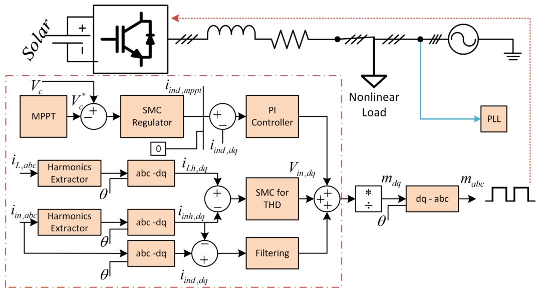
A control structure of an SMC is proposed in Figure 9, where THD for a PV-based system has been reduced using SMC. For this system, the sliding surface design and reaching law has been evaluated as:
e d = i h d * i d , e q = i h q * i q
where i h d * , i h q * are the harmonic current references, and i d , i q are the measured grid currents in the synchronous d q -frame.
S d = e d + λ e d d t , S q = e q + λ e q d t
where λ > 0 is the integral gain for steady-state error removal.
S ˙ d = k d sat S d ϕ , S ˙ q = k q sat S q ϕ
where k d , k q > 0 are reaching gains, ϕ > 0 is the boundary layer width, and sat ( ξ ) = sgn ( ξ ) min { 1 , | ξ | } .
v i d * = v g d + L eq i ˙ h d * + λ e d ω i q + R eq i d + L eq k d sat S d ϕ ,
v i q * = v g q + L eq i ˙ h q * + λ e q + ω i d + R eq i q + L eq k q sat S q ϕ ,
where v g d and v g q are grid-voltage components in the synchronous d q -frame. The parameters L eq and R eq represent the equivalent series inductance and resistance between the inverter and PCC. When the original model only includes the filter branch, L eq = L f and R eq = R f . When the supply-line or grid impedance is also included, L eq = L f + L g and R eq = R f + R g . If resistance is neglected in the cited model, R eq = 0 .
e v = V * V , S v = e v + k v e v d t
i r e f = α e v + k v e v d t + β sat S v ϕ v
where V is the DC-link voltage, V * is its reference from MPPT, i r e f is the fundamental current reference, α is a conversion factor from DC power to d q current, k v > 0 is the voltage-loop gain, β > 0 is the switching gain, and ϕ v > 0 is the voltage-loop boundary layer width.

3.2. Structure-Based SMC Variants for Grid-Tied Inverters

The classification of SMC in power electronics is not limited to the control objective, rather it also depends on the structural formulation and complexity [70]. The evolution of SMC has resulted in various variants to attain robustness and invulnerability against constraints, i.e., dynamic loads, noise, switching losses, and real-time integration [71]. These variants are mainly classified as conventional SMC, observer-based SMC, adaptive SMC, and Hybrid SMC. The conventional SMC is referred to as fourth-order control with convention leaching-law implementation [72]. The control structure for conventional SMC, observer-based SMC, adaptive SMC, and hybrid SMC are presented in Figure 10, Figure 11, Figure 12 and Figure 13.
The classic control law is presented as:
u ( t ) = u e q ( t ) k · sign ( s ( x , t ) )
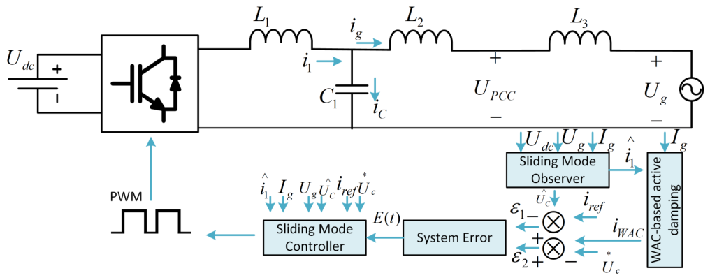
Here, u e q is the equivalent control obtained from nominal dynamics. The k · sign ( s ) term is responsible for enforcing the control law to obtain robustness. Under uncertainties, this type of controller is often exposed to the chattering phenomenon which has higher-order frequency components and limited adaptability. The authors of [27,39] proposed a discrete SMC technique to track the grid current by significantly reducing the chattering effect while maintaining robustness and higher operational performance. In observer-based SMC control, the external disturbances are estimated through a super-twisting observer or a simple disturbance observer. These additional features enable resilient control under weak grid scenarios and faulty conditions. The disturbance d ^ is estimated through an observer-based control loop which further updates the control input as:
d ^ ( t ) = y ( t ) y ^ ( t ) , u ( t ) = u n o m i n a l ( t ) d ^ ( t )
where d ^ ( t ) is the estimated disturbance, y ( t ) is the measured output, and y ^ ( t ) is the estimated output from the observer. The term u ( t ) is the compensated control input, and u n o m i n a l ( t ) is the nominal control input before disturbance compensation.
A fourth-order SM observer was presented in [74], which is capable of source-side voltages in a hybrid power system. Similarly, observer-based SMC has been proposed in [46,75] for enhanced voltage tracking and current control, respectively. In adaptive SMC, the dynamic gains and sliding surfaces are updated through adaption laws and real-time feedback systems. It includes terminal sliding surfaces and gain tuning through Lyapunov conditions. In this case, an adaptive term is introduced in the sliding variables which can be represented as:
s ( t ) = e ( t ) + λ ( t ) e ( t ) d t , λ ˙ = γ e ( t ) 2
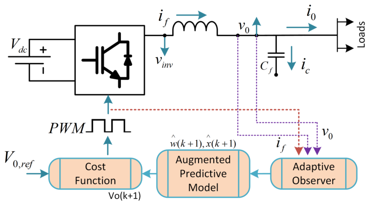
where s ( t ) is the sliding surface, e ( t ) is the tracking error, and λ ( t ) is the adaptive integral gain. The parameter γ > 0 is the adaptation gain, and λ ˙ denotes the time derivative of λ ( t ) . In contrast to these controllers, hybrid SMC is a combination of nonlinear or intelligent controllers, i.e., deep reinforcement learning, model predictive control (MPC), fuzzy logic or other optimisation techniques [76,77]. The core objective of this controller is to provide robustness while reducing chattering and providing enhanced tracking. A PSO-tuned second-order SMC was presented in [78] for active-power regulation in a single-phase voltage-source inverter. In this approach, PSO is used to select the super-twisting controller gains λ and W, while the tracking performance is evaluated using error-based indices such as the integral absolute error (IAE) and integral square error (ISE).
u = λ | s | ρ sgn ( s ) + u 1 , u ˙ 1 = W sgn ( s ) ,
where s is the sliding variable, and λ , W, and ρ are positive controller parameters. The performance indices are defined as
IAE = 0 t | e ( t ) | d t , ISE = 0 t e 2 ( t ) d t .
where IAE is the integral absolute error, ISE is the integral square error, and e ( t ) is the tracking error over the time interval from 0 to t. These SMC variants provide robustness complimented with unique features; however, there are certain trade-offs associated with the selection of these techniques. Conventional SMC has a simple control architecture with less computation complexity but it is more prone to the chattering effect [79]. Observer-based SMC is useful when some current, voltage, or disturbance signals are not directly measured. The observer estimates these signals and feeds them to the control law, which supports reduced-sensor operation and improves the response under disturbed conditions [80]. Moreover, adaptive SMC is a more flexible framework with a simple architecture and efficient transient correction in power systems. Hybrid SMC has the most unique characteristics as it integrates intelligent controllers to provide a state-of-the-art solution to the compromise of computational complexity [81]. In Figure 13, the tracking error follows the convention e = u ac u ref , where u ac is the inverter output voltage and u ref is the reference voltage. The fuzzy system estimates η ^ , which represents the estimated upper bound of the disturbance-observer error used in the sliding mode control law.
These controllers have versatile operational performance under different grid contentions. The selection criteria depend upon the objectives (voltage or current control), hardware selection (DSP or Hardware-in-the-Loop), and grid conditions (balanced or unbalanced). The inner control loop in grid-tied inverter applications is responsible for output current regulation. It requires improved convergence to track reference signals appropriately, that is, current tracking in d q -frame. The sliding surface for this objective can be formulated for the direct- and quadrature-axis current components as:
s k ( t ) = i k , ref ( t ) i k , inv ( t ) , k { d , q } ,
where d and q denote the direct- and quadrature-axis current components in the synchronous d q -frame.
Figure 13. Control structure of hybrid SMC [82].
Energies 19 03052 g013
The authors of [43,83], proposed a discrete-time SMC (DSMC) and super-twisting SMC (STMC), respectively, for an inner loop architecture with fast convergence and enhanced chattering reduction. The outer loop usually has a slower response and is responsible for voltage regulation or power governance. It is responsible for voltage regulation across DC-link and manages active/reactive power injection. Moreover, reference signals for the inner loop are generated at this level. The sliding surface modelling for this loop is typically based on the voltage error.
s v ( t ) = ( V r e f V d c ) + λ ( V r e f V d c ) d t
where s v ( t ) is the voltage sliding surface, V r e f is the reference DC-link voltage, V d c is the measured DC-link voltage, and λ is a positive integral gain. Cascaded or dual-loop SMC is a more sophisticated architecture than inner- and outer-loop architectures. Here, SMC manages both fast and slower control signals by incorporating reference signals generated from the outer loop and taking them as input to the inner loop. This framework is suitable for multifunctional inverter-based applications. It has been deployed in GFM inverters with unbalanced distribution networks. Higher efficiency in module design and parametric tuning can be achieved by utilising this control strategy. It also provides certain benefits with respect to grid-code compliance, harmonics mitigation, chattering reduction, and resilience under varying load [84]. In the next section, we will elaborate the application of SMC in single-phase and three-phase inverters, voltage and current control, harmonic suppression, weak grids, and low inertia systems. A summary of different SMC variants for grid-tied inverters is presented in Table 4.

4. Applications of SMC in Grid-Tied Inverters

Sliding mode control has demonstrated notable reliability when addressing emerging challenges in grid-tied inverter-based systems. As described in previous sections, it has the versatility to cope effectively with external disturbances, parametric variations, and system nonlinearities. These attributes make it a competitive alternative to existing control strategies, particularly in weak grids, islanded mode, and distributed energy sources. In this section, the impact of SMC in a grid-tied inverter ecosystem is elaborated, supported by comparison of existing studies, particularly in key focus areas, i.e., single- and three-phase inverters, voltage mode and current model, weak grids, and harmonics mitigation. Moreover, hardware setups, i.e., HIL devices, are elaborated and their integration with SMC is discussed.

4.1. Single-Phase vs. Three-Phase Inverters

Single- and three-phase inverter architectures require sophisticated control objectives, unique design choices, and degrees of freedom [85]. The transformation of control signals in the time-domain can be carried out in stationary, i.e., α β , or rotating frames, i.e., d q . The selection of these transformations has a major impact on the formulation and implementation of SMC in control loops [86]. Single-phase inverters are often subjected to several limitations because of insufficient orthogonal-phase components [87]. In this scenario, α β transformation is often used to implement SMC in the time-domain to achieve several operations, i.e., voltage regulation, grid synchronisation, or current tracking. These approaches usually target nonlinear load suppression and harmonics mitigation without the interference of decoupled current axes [88]. The authors of [89] proposed a novel Discrete-time Fuzzy Integral SMC (DIFISMC) variant. The proposed technique has a unique mechanism to integrate the integral sliding surface with a fuzzy logic technique. The proposed technique is capable of reducing THD from 9.13% to 3.10%. Moreover, it improves the algorithm convergence when exposed to highly distorted loads. The sliding surface in the system can be termed as:
s v ( t ) = v r e f ( t ) v o u t ( t ) + λ ( v r e f v o u t ) d t
where s v ( t ) is the voltage sliding surface, v r e f ( t ) is the reference voltage, v o u t ( t ) is the output voltage, and λ is a positive integral gain. In contrast, three-phase inverters can provide control for active and reactive current components by utilising d q or α β reference frames [90]. This unique feature originates the concepts of more advanced SMC controllers, i.e., super-twisting, fractional-order, or terminal controllers [91].
The authors in [83] presented a current controller for an LCL-based three-phase inverter. The objective of resonance suppression was achieved by combining a discrete observer with a proportional resonant (PR) controller. Moreover, a super-twisting SMC (STSMC) was incorporated as a three-phase NPC inverter. The proposed controller reduces the harmonics distortion by up to 2% and provides robust transient stability in the presence of voltage imbalances. In these cases, the sliding surfaces can be modelled as:
s d ( t ) = i d r e f ( t ) i d ( t ) , s q ( t ) = i q r e f ( t ) i q ( t )
where s d ( t ) and s q ( t ) are the sliding surfaces for the d- and q-axis current loops. i d r e f ( t ) and i q r e f ( t ) are the reference currents, while i d ( t ) and i q ( t ) are the measured currents in the d q -frame. and the super-twisting control law is represented as follows:
u ( t ) = k 1 | s | 1 / 2 sign ( s ) k 2 sign ( s ) d t
where u ( t ) is the switching control signal, s is the sliding variable, and k 1 and k 2 are positive control gains. The term sign ( s ) defines the switching action. The grid distortions can be significantly reduced by utilising such control laws and sliding surfaces. Furthermore, these controllers can be integrated with a hierarchical control system due to the inherited modularity of the d q -frame-based SMC architecture, resulting in more sophisticated compliance with grid standards.
Due to insufficient observability, single-phase inverter control mainly relies on a basic heuristic SMC architecture. Meanwhile, three-phase systems can incorporate more sophisticated, robust, and complex SMC variants. This results in higher performance and enhanced integration with real-time interfaces. These sophisticated controls allow users to achieve better power flow, smoother current injection, and robust THD under different scenarios, i.e., weak grid conditions. A comparative analysis of SMC variants on the basis of inverter types is presented in Table 5. The Table compares the different studies on a difference basis, i.e., higher order, hybrid strategy, and hardware integration.

4.2. Voltage-Mode vs. Current-Mode Control

SMC has versatile properties and can be integrated with both current and voltage control architectures [99]. The selection of current-mode and voltage-mode strictly relies on the application domain and requirements, i.e., grid-tied inverter role, regulation objective, and control parameters [100].
When it comes to grid-tied inverter output voltage regulation or DC-link voltage stability, voltage-mode SMC architectures are utilised. The application areas span boost converters, standalone inverters, and energy storage instances [101]. In this structure, the control law directly impacts the duty cycles of the switching devices, i.e., MOSFETs to achieve voltage stability by tracking signals. The sliding surfaces can be designed as [102].
s v ( t ) = v r e f ( t ) v o u t ( t ) + λ ( v r e f ( t ) v o u t ( t ) ) d t
where s v ( t ) is the voltage sliding surface, v r e f ( t ) is the reference voltage, v o u t ( t ) is the output voltage, and λ is a positive integral gain.
In this design, an integral term is introduced to enhance the steady-state convergence and disturbance rejection. The authors of [103] proposed an integral SMC (ISMC) with the core objective of regulating the voltage across the capacitor in a dual active bridge with a Phase-shifted PWM (PS-PWM) technique. The proposed technique reduced the THD by up to 2.4%. Moreover, in [104], a digital voltage-mode SMC was used with mutation logic for two-leg inverters. The proposed method utilises discrete-time modeling to improve voltage ripple suppression under switching disturbances.
In contrast to voltage-mode SMC, current-mode SMC has been more often assessed in grid-tied applications, i.e., LCL-based inverters. Its core objective is to inject current to the grid while while tracking active and reactive power. In this case, d q -frame transformations are usually used for control implementation [105]. Here, the sliding surfaces are designed to enable active and reactive component handling. The sliding surfaces can be termed as:
s d ( t ) = i d r e f ( t ) i d ( t ) , s q ( t ) = i q r e f ( t ) i q ( t )
where s d ( t ) and s q ( t ) are the d- and q-axis sliding surfaces. i d r e f ( t ) and i q r e f ( t ) are the reference currents, while i d ( t ) and i q ( t ) are the measured currents in the d q -frame. The super-twisting control laws for this architecture can be modeled as:
u i ( t ) = k 1 | s i ( t ) | 1 / 2 sign ( s i ( t ) ) k 2 sign ( s i ( τ ) ) d τ
where u i ( t ) is the control input for the i-th channel, s i ( t ) is the corresponding sliding variable, and k 1 and k 2 are positive control gains. The term sign ( · ) denotes the switching function, and τ is the integration variable. The authors of [43,87] evaluated the performance of current-mode SMC architectures by proposing fixed-time SMC and STSMC, respectively. Fixed-time SMC was implemented or T-type VSI, which provides robust THD reduction in simulated environment. STSMC achieved less than 1.5% THD reduction by using a fixed switching frequency.
Voltage-mode SMC usually operates more slowly than current-mode SMC and has a more susceptible nature when exposed to load-induced dynamics [106]. However, it uses a simple architecture. The current-mode control architecture has a faster response time and higher flexibility and accuracy. These attributes make it a suitable choice for grid synchronisation to satisfy grid standards, i.e., IEEE-519 [107]. In cascaded control structures, a hybrid approach is utilised, where voltage-mode SMC is used in the outer loop for power control or voltage regulation [108]. The inner loop is typically based on the current-mode SMC, which provides a faster response and generates reference signals for modulation. However, the selection criteria of these topologies relies on the desired operation of the control architecture, i.e., current compliance or voltage stability [109]. A comparison of various studies on voltage-mode and current-mode SMC is presented in Table 6, explaining the modes, SMC variants, and hardware integration.

4.3. Harmonic Suppression and Standard Compliance

In DERs, maintaining grid power quality is a crucial factor. The grid-tied setups are designed in a way to interface with sensitive load or weak grids. In this regard, THD becomes a vital factor derived by grid standards, i.e., IEEE-519 and IEEE-1547 [118,119]. This standard describes the objectives for designing electric systems to cope with linear and nonlinear loads by keeping THD within prescribed limits. The nonlinear structure of SMC makes it a significant choice in harmonics suppression. Moreover, it can significantly compensate high-frequency interferences unlike conventional controllers, i.e., PI or PR [120]. Conventional controllers require resonant compensations and tuning at specific frequency setpoints to reduce harmonics in the power system [121]. A comprehensive comparison of SMC with conventional control strategies will be discussed in Section 4.
The phenomenon of higher-order harmonics rejection in SMC originates from its capacity to force system properties on the sliding surfaces regardless of disturbances introduced to the system. The design of a sliding surface for harmonics distortion in current can be modeled as:
s ( t ) = i r e f ( t ) i ( t )
where i r e f ( t ) is generated from grid-synchronized phase lock loops (PLLs), or power references. These sliding surfaces can be optimised further by introducing fractional-order terms as:
s f o ( t ) = D α [ i r e f ( t ) i ( t ) ] , 0 < α < 1
where D α denotes a fractional-order derivative [47].
The authors of [43] implemented super-twisting SMC (STSMC) for a dynamic voltage restorer (DVR) application, achieving 1.5% THD by maintaining fixed-frequency operation. Moreover, in [47], a fractional-order SMC (FOSMC) was formulated for grid-tied DSTATCOM integrated with battery energy storage. The proposed control was tested in both grid-connected and islanded mode providing 1.04% and 0.48% THD, respectively. A three-phase STSMC for NPC converter was proposed in [58] under unbalanced conditions. The proposed controller ensured grid compliance with IEEE 1547 and maintained THD up tp 2%. In addition to these strategies, observer-augmented SMC variants also perform significantly better against THD. The authors of [122] proposed a unique integral synergetic control (ISC) for a multilevel inverter application. The proposed strategy ensured zero steady-state error and robust transient response under harmonics rejection. Furthermore, in [123,124], integral terminal SMC and FOSMC were proposed, respectively.
These strategies significantly reduce the THD and overshoots in harmonics-rich transients. When designing an SMC variant to incorporate THD, it is important to formulate the sliding surfaces according to the LCL filter dynamics. Moreover, switching frequency limitations should be considered as system constraints. The control system should be validated across several parameters, i.e., partial loading and dynamic power commands, etc. Table 7 provides a comparison of studies carried out on different variants of SMC and their contribution to THD reduction.

4.4. Weak Grids, Low Inertia, and Islanding Scenarios

In the recent era, high penetration of distributed PV systems is being experienced in the power grid which has indicated consequential stability and operational vulnerabilities in distribution networks especially under balanced conditions [131]. Such challenges pose a great threat to overall grid stability. To address these issues, there is a need to develop robust control strategies. These inverter control models should be capable of providing unbalanced voltage compensation, phase-level voltage stability, and virtual inertia to improve frequency stability in the power system [132]. This transition has led to the reduction of synchronous machines in the power systems, leading to low-inertia systems. To cope with these low-inertia systems, existing control architectures are exposed to several challenges, i.e., weak signal tracking, voltage instability, and resonance of LCL filters [133]. Remote distribution feeders with high line impedance are more exposed to this effect. Moreover, islanded microgrids without sufficient grid support often experience stability issues. In this context, SMC offers particularly effective solutions due to its unique abilities to handle disturbance and rapid response against system restoration. In the context of weak grids, SMC control designs revolve around fast current tracking, voltage regulation, and robust PLL operation. Fast current tracking is necessary to maintain current symmetry to avoid undesired triggering in protection systems [15]. Moreover, voltage regulation is crucial to maintain a low short-circuit ratio (SCR) during faults, switching operations, and sag/swell operations. Robustness in PLL operations ensures reliable frequency tracking in GFM inverters and impedance shaping for GFL inverters [134]. In low-inertia systems, various SMC architectures have been reported in the literature, i.e., dual-loop structures, terminal SMC for PLL, super-twisting, and observer-based SMC. The authors of [86] proposed a dual-loop SMC by using FPGA for a three-phase LCL inverter. The proposed technique shows sufficient dynamic stability with low SCR. Moreover, ref. [94] employed a QSG-DSOGI-based terminal SMC to enhance phase tracking by lowering the SCR. A control structure of SMC for weak grid applications has been illustrated in the Figure 14.
The authors of [58] focused on the utilisation of STSMC for harmonics mitigation under unbalanced conditions. In a weak grid, SMC sliding surfaces can be designed to cope with sags/swells and grid disturbances as:
s ( t ) = i r e f ( t ) i ( t ) + α 0 t ( i r e f i ) d t
where s ( t ) is the current sliding surface, i r e f ( t ) is the reference current, i ( t ) is the measured current, and α is a positive integral gain. The reaching law for terminal convergence can be represented as:
s ( t ) = e ( t ) + λ | e ( t ) | δ sign ( e ( t ) ) , 0 < δ < 1
where s ( t ) is the sliding surface, e ( t ) is the tracking error, λ is a positive surface gain, and δ is a fractional exponent satisfying 0 < δ < 1 . The term sign ( e ( t ) ) denotes the sign function.
By developing such a sliding law, precision and accuracy can be achieved for under-voltages and load mismatches. Table 8 provides a comprehensive comparison of studies carried out on weak grid applications where various variants of SMC have been implemented. These strategies provide robust performance against weak grids and islanded mode operations. The high performance of SMC makes it a leading choice for GFM and GFL inverters integrated with next generation low-inertia power systems.

4.5. Hardware Implementation Considerations

Theoretically, SMC offers invulnerable, reliable, and robust performance for time-varying systems. However, it has several challenges when it comes to the hardware integration with real-time power systems [86]. These challenges include several important issues, i.e., switching constraints, finite computation bandwidth, quantitation effects, and sampling delays [87]. Rigorous testing is required to minimise the gap between theory and practical implementation on real-time platforms, i.e., HIL. These platforms include HIL validation using dSPACE and OPAL-RT, low-latency real-time implementation on FPGA and DSP, MATLAB/Simulink, and embedded target validation [136,137].
High-fidelity real-time simulators such as dSPACE and OPAL-RT have been widely used to test SMC-based inverter control under dynamic and faulted grid conditions [138]. These platforms allow precise replication of real-world operating scenarios with programmable grid voltages, unbalanced loading, and harmonic distortion [140]. These platforms allow users to precisely test real-time scenarios, i.e., faulted grid condition with tunable grid voltages, harmonics distortion, and unbalanced conditions. These simulators allow fixed-frequency emulations, which enable predictable PWM generation and enhance the accurate testing of SMC actions. Field-Programmable Gate Array (FPGA) and Digital Signal Processing (DSP) are usually preferred for fixed-time variants and high-frequency current-mode SMC [142]. Micro-level control can be achieved through these hardware setups. These setups are specially used for multi-kHz switching application, dual-loop SMC controllers, and current-mode grid control operations [143].
MATLAB/Simulink offers rapid prototyping, discrete-time solvers, and compatibility with other real-time simulators [144]. This setup is quite useful to design observers, parametric tuning, and Lyapunov-based gain selection. Moreover, Simulink offers simple fractional-order blocks integration and adaptive learning agents. In this regard, SMC strategies are evaluated before integrating to the real-time platforms.
An important issue in hardware implementation is the conversion of continuous time SMC laws to discrete-time formate. A typical switching law in SMC architecture is represented as:
u ( t ) = u e q k · sign ( s ( t ) )
where u ( t ) is the control input, u e q is the equivalent control term, k is a positive switching gain, and s ( t ) is the sliding variable. The term sign ( s ( t ) ) denotes the switching function.
This type of switching law is often modified by using either saturation functions or PWM logic. This parameter helps to reduce the chattering effect and ensures compatibility with hardware setups [39,95].
sat ( s / ϕ ) = 1 s > ϕ s / ϕ | s | ϕ 1 s < ϕ
where sat ( s / ϕ ) is the saturation function, s is the sliding variable, and ϕ is the boundary-layer thickness. The saturation function limits the switching action within the boundary layer to reduce chattering.
A comparison of various studies is presented in Table 9, where various platforms and SMC variants are compared with respect to validation setup and performance highlights. Over time, SMC strategies have matured and many studies have tested these control schemes on real-time hardware integration. These setups favour a dual-loop SMC architecture to validate robustness under various grid conditions, i.e., weak grid, unbalanced distribution networks.

5. Comparative Analysis with Other Control Strategies

In previous sections, a comprehensive overview of SMC has been presented with respect to evolution, different variants, and application areas. However, it is important to compare SMC with other conventional controllers, i.e., PI, MPC, and H . In this section, the performance of SMC is compared with classical and advance control methods. Several hybrid architectures exist in the literature which provide enough evidence to support the argument that SMC behaves efficiently when combined with hybrid architectures, i.e., artificial intelligence-driven controllers.
Conventional controllers, i.e., proportional-integral (PI), H , and model predictive control (MPC) have been widely used in power electronics applications [145]. They have linear characteristics that are often associated with strict limitations. These factors make them vulnerable for the current era’s modern grid-tied inverter applications [146]. These control strategies struggle to cope with the challenges related to variable demand supply, weak grid conditions, unbalanced distribution systems, and nonlinear dynamics [147]. The PI control strategy has higher adaptability due to its simple architecture, minimum computational complexity, and explicit gains. Moreover, the performance of PI controllers is effective under slow disturbances with nominal conditions [148]. PI controllers are usually connected with d q -frame for voltage or current control loops. They display intuitive behaviour against parametric variations. This feature makes them vulnerable against system disturbances and model uncertainties [62].
The authors of [87] tested a PI controller under unbalanced conditions. The proposed control was implemented on a three-level VSI and the results showed failure to maintain tracking under unbalanced situations. The system was tested using SMC and the results showed a clear indication of system stability under unbalanced conditions. The proposed architecture successfully maintained current tracking and minimised steady-state error due to the unique control law and efficient convergence properties.
Another conventional controller, MPC has unique capabilities to provide reliable dynamic performance-based system trajectories prediction over a finite horizon [149]. Moreover, the control actions initiated by this strategy are subjected to systems constraints with the objective to minimise costs. The cost function for MPC can be formulated as:
u * = arg min u ( k ) i = 0 N x ( k + i | k ) x r e f 2 + ρ u ( k + i ) 2
where x ( k + i | k ) denotes the predicted state, x r e f is the reference trajectory, and ρ is a control weighting factor. In multilevel and grid-tied inverters, MPC has been utilised in current and voltage control loops [150]. Despite its robustness, MPC involves higher computational complexity and is limited in its ability to model plant functions. However, its robustness can be maximised by integrating it with SMC [151]. MPC has been effectively applied in voltage and current control of multilevel inverters and grid-tied converters. However, its real-time viability is challenged by computational complexity and sensitivity to plant modelling errors [152]. The authors of [153] proposed a hybrid control architecture by combining MPC with integral SMC (ISMC). The proposed architecture was implemented in an LCL-filtered VSI and achieved enhanced dynamics response and improved disturbance rejection compared with the conventional MPC. In addition to MPC, the H control architecture is based on optimal control theory with a core objective to minimise gains during uncertainties to control output signals [154]. It has unique attributes which make it suitable for implementation on systems where structured uncertainties are present [155]. Nevertheless, for nonlinear systems requiring faster switching operations, H control is often exposed to complexities associated with Riccati and LMI issues during gain tuning [156]. Several studies have indicated that this method can achieve robust regulation in linear domain applications. However, H is less adaptable than SMC under real-time applications requiring nonlinear loading or grid variations [157,158].
The conventional control strategies have been widely tested and have evolved over time. Each technique has unique attributes associated with it. When it comes to low cost and complexity, PI control emerges as a good choice but is subject to limited reliability against harmonic distortion and load variations. MPC improves prediction-based accuracy but is computationally intensive and model-sensitive. H control offers structured robustness but lacks flexibility for switching converters or highly nonlinear systems. In contrast to these, SMC has unique features, i.e., finite-time convergence, discrete control laws, faster operations, and superior disturbance rejection. In Table 10, an overview of studies is presented where conventional controllers are compared with different variants of SMC. The comparative analysis shows the dynamic benefits and PQ benefits associated with the SMC variants over conventional controllers. It provides sufficient evidence to support SMC selection over the conventional algorithm.
In contrast to conventional controllers, intelligent controllers have emerged as a robust and efficient alternative to classical control systems for power electronics applications. They execute effectively in system conditions which change unpredictably and where accurate mathematical models are unavailable [167]. Reinforcement learning (RL), artificial neural networks (ANNs), fuzzy logic (FL), and regression-based controllers are often reported as intelligent architectures for control loops [168]. When integrated with SMC, these controllers can provide robust solutions for grid-tied inverter control. Rule-based reasoning is used to model nonlinear relationships in FL controllers [169]. In such systems, there is no requirement to have an accurate mathematical definition. When integrated with SMC, FL supports adjustment of tunable parameters, i.e., gains or boundary layer conditions. Such hybrid models significantly reduce the chattering phenomenon and improve disturbance rejection. The authors of [89] proposed a discrete-time integral SMC (DTFISMC) for a single-phase inverter application with rectifier loading. The control gain k was modified through a fuzzy layer, represented by equation:
k ( t ) = f ( μ error , μ error ˙ )
Here, μ represents the fuzzy membership values associated with linguistic terms (e.g., “small,” or “large”). The strategy achieves THD reduction from 9.13% to 3.01% in discrete-time SMC, which highlights improved waveform shaping and robustness to parameter drift. In recent years, machine learning has been explicitly implemented in power system applications. Similarly, neural networks (NNs) have been used for functional approximation in SMC frameworks [170]. These algorithms are very robust in unknown parameter estimation and control law identification. In some cases, neural networks have been used to replace the entire sliding surface, resulting in a very novel approach for power electronics applications [171]. Although, it provides a very promising solution, it requires extensive offline training, which poses a huge challenge in ensuring Lyapunov stability. NNs and other deep learning algorithms provide model-based solutions for integration in control loops [172]. However, reinforcement learning (RL) is a model-free algorithm, which provides robust control which interacts with the environment, exchanges variables through agents, and improves controller performance by reward maximisation [26]. The authors of [42] proposed a hybrid controller based on RL-SMC for MPPT and current regulation in a PV-grid system. An ε -greedy Q-learning algorithm is used to generate optimal duty cycles for the MPPT block in this article. Meanwhile, SMC tracks the resulting current reference with high fidelity. The results showed that the system achieved 99.8% MPPT accuracy and THD reduction to 3.3%. The results obtained show that the proposed method outperformed FL-SMC and incremental conductance methods. The Q-learning update rule can be defined as:
Q ( s , a ) Q ( s , a ) + α r + γ max a Q ( s , a ) Q ( s , a )
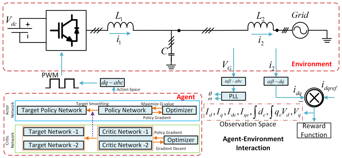
where Q ( s , a ) is the value function, α is the learning rate, γ is the discount factor, and r is the immediate reward based on output power and voltage ripple. An agent - environment interaction for grid-tied inverter has been cited in the Figure 15. Moreover, Table 11 provides a comparison of various studies where intelligent controllers have been used with SMC variants resulting in distinctive performance. Apart from machine learning, fuzzy logic, and conventional methods, meta-heuristic algorithms, i.e., particle swarm optimisation (PSO), can be a good choice to develop a hybrid model with SMC. The authors of [78] proposed a PSO-based algorithm to tune 2nd-order SMC combined with a super-twisting algorithm. The PSO is responsible to tune gains k 1 and k 2 as:
u ( t ) = k 1 | s ( t ) | 1 / 2 sign ( s ( t ) ) k 2 sign ( s ( t ) ) d t
where u ( t ) is the control input, s ( t ) is the sliding variable, and k 1 and k 2 are positive control gains. sign ( s ( t ) ) is the switching function. The results indicate that the hybrid PSO-SMC design achieved a 33–66% improvement in dynamic response and complied with IEEE 1547 ramp-rate constraints.
Intelligent controllers significantly improve the flexibility and performance of control systems. However, there are certain challenges associated with these strategies, i.e., high computational overhead, stability certification, issues where guaranteeing Lyapunov-based convergence is nontrivial, and hardware integration issues [183]. On the other hand, conventional SMC methods provide robust convergence and model-independent behaviour requiring expert-defined gain tuning, sliding surfaces, and control law definitions. There are certain trade-offs associated with the selection of these control strategies, depending upon the system requirements.
Hybrid approaches utilising SMC with other techniques, i.e., PI, PSO, MPC, FL, or AI-based algorithms, are becoming more mature with every passing year. The core objective of these hybrid architectures is to enhance operational robustness by leveraging flexibility to eliminate steady-state errors by improving robustness associated with SMC [184]. The SMC and PI controllers are the most widely used techniques in outer control loops. Since SMC provides fast transient responses in the inner loop, a PI control is employed in the outer loop to eliminate residual steady-state errors by maintaining average power balance [5]. The authors of [43], proposed a super-twisting SMC (STSMC) with PI controller for voltage regulation in the outer loop. The proposed hybrid structure resulted in a zero offset operation and fast response. The proposed cascaded approach resulted in THD reduction up to 1.5% by maintaining a fixed switching frequency. Table 12 presents a comparison of studies where hybrid strategies have been implemented and the benefits achieved. Moreover, in Table 13, a qualitative head-to-head comparison of several strategies is presented, comparing sag recovery time, THD, computational power consumed, and stability mode.

6. Emerging Trends and Future Research Directions

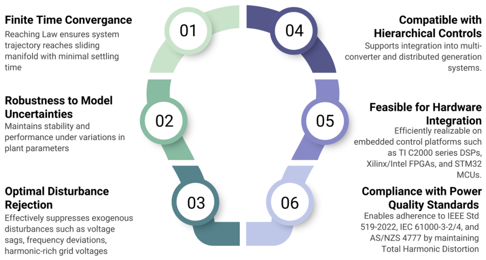
The discussion in the previous section highlighted the unique attributes of SMC, including finite-time convergence, disturbance rejection, robustness to model uncertainties, and compatibility with hierarchical control architectures. These distinctive features of SMC are illustrated in Figure 16. Considering these attributes, it is important to explore the potential emerging trends and future research direction for SMC technologies. This section explores emerging trends in SMC, including data-driven gain tuning, hardware validations, multi-part topologies, regulatory alignment considerations, and quantum computing-based optimisation. Additionally, several open research questions associated with these advancements are discussed. We are currently in the era of AI, where data-driven techniques and the emergence of large language models are increasingly influencing the development and implementation of advanced control technologies. In this regard, implementing deep-reinforcement learning (DRL) techniques, i.e., DQN, AlphaGo, PPO, Rainbow DQN, MuZero, MARL, or AlphaProof can bring a paradigm shift in the control system’s performance. The authors of [196], proposed an actor–critic policy for optimisation of cascaded-PI gains by changing the Simulink model to a Python-based co-simulation environment. The results obtained from the study indicated that the DRL method helped to reduce 40% of post-fault frequency swings without any losses. Similarly, a continuous action DRL model based on a deep deterministic policy gradient (DDPG) has been integrated with the sliding observers of higher-order SMC in [197]. The results indicate a 28% improvement in the voltage settling time by maintaining the overshoot under 1%. A feed-forward neural network (FF-NN) approach was integrated with fast terminal super-twisting SMC (FT-STSMS) to reduce the partial shaving. The proposed FF-NN approach predicted the perturbation elements to reduce the higher-order chattering effect in the SMC. Although DRL techniques offer promising results, this comes at the cost of higher computational complexity. Moreover, the run time stability needs more attention due to limited implementation of Lyapunov safety or boundary layers in the policy learning algorithms. In these scenarios, more research is needed in the domains of interpretation ability, computational asymmetry, disturbance convergence, and hardware realism.
Recently, various investigations have been carried out on multi-scale forecasting for SMC-based voltage-based inverters to initiate corrective action before disturbance sensing. In [198], an inner predictive control based on the CNN-LSTM was proposed with SMC to forecast PV power and local load. The results indicated that it kept the point-of-common-coupling (PCC) within 1% during 15% changes. The proposed approach outperformed the conventional droop technique by approximately 35% in transient state error. Furthermore, in [199], a hybrid bi-LSTM algorithm was trained on substation data to predict day-ahead mean absolute percentage error (MAPE). Such predictions can serve as reference points for SMC-based inverters, enabling accurate quarter-hour rescheduling. Most studies on these technologies have been limited to simulation-based setups. With advancements in OPAL-RT platforms, such as the OP1420 PHIL, further research can now be conducted using real-time digital simulators. Similarly, Python (version 3.14) can be integrated with the HIL-606 simulator through the Typhoon-HIL API, enabling the use of built-in libraries, multiple Python versions, and necessary software upgrades. HIL-606 is a fourth-generation simulator with advanced control system testing capabilities, supporting up to 24 distributed energy resource (DER) models in real-time with short time-step resolution. Through the Python API, various system parameters—such as load adjustments, voltage amplitudes, inverter settings, and other operational variables—can be modified dynamically. Libraries like Pandas and NumPy are particularly effective for analysing these real-time scenarios. Based on the analysis, parameters including SMC gains, control loop settings, voltage levels, and PV penetration can be adjusted to evaluate the effectiveness of proposed control strategies. Additionally, fault injection can be introduced to further assess system performance. This approach allows real-time recording of all operational parameters, which can then be stored for post-processing. Subsequent data analysis enables comparison and refinement of control techniques. Moreover, state-of-the-art hyperparameter tuning methods can be implemented, and their performance systematically evaluated to optimise control strategies. Table 14 provides a comparison of several emerging trends with respect to their maturity and and research focus. Moreover, Table 15 highlights the possible research directions for sliding-mode control in grid-tied inverter applications.
Recently, quantum computing has emerged as a new computational tool that manipulates information qubits. This capability allows physical devices to explore exponentially larger search spaces in a single computation pass. In this context, gate-based quantum circuits can process all control gains simultaneously, in contrast to conventional sequential processing of gain vectors. Research indicates that noisy intermediate-scale quantum (NISQ) devices can outperform classical heuristic algorithms, particularly in convex optimisation problems. The quantum approximate optimisation algorithm (QAOA) can be utilised for SMC-based grid-tied inverter applications. An encoding mechanism for the multi-loop cost function can be utilised for optimising the Hamiltonian to achieve smoother convergence and better efficiency. For example, ref. [205] proposed a quantum genetic algorithm (QGA) to tune a PID prefilter for a microgrid inverter. The results indicated THD up to 1.03% as compared to the GA-PSO variant. Quantum methods may also replace deep reinforcement learning (DRL) frameworks for more efficient optimisation and gain tuning; as noted in [206], quantum approaches required 15% fewer training epochs than a deep Q-network while achieving comparable performance. These findings suggest that quantum computing could play a pivotal role in future optimisation landscapes, offering unique advantages in speed, solution quality, and scalability. Hardware road maps from IBM and other vendors indicate that by the end of 2027, platforms capable of real-time testing of such strategies will be available. While developing these techniques, it is critical to design cost functions aligned with Lyapunov stability criteria and relevant boundary conditions. By establishing fair benchmarks, reliable and robust tools can be developed for utility-scale grid-tied inverters.


7. Conclusions

The review article presented a comprehensive overview of SMC strategies. The article focused on SMC classification, variants, and applications in grid-tied inverters. The findings indicate the robustness, adaptability and practice significance of SMC architectures. Moreover, SMC is highly favourable for the nonlinear and uncertain dynamics of modern power systems as it provides robust operations, i.e., disturbance rejection, finite time convergence, and faster response. These attributes make it dominant in the control systems landscape experiencing low inertia, harmonics, and stability issues. This article classifies the different SMC variants according to their applications, control schemes, and performance. Apart from this, hardware platforms, i.e., HIL and FPGA, etc., have also been discussed. Moreover, the role of intelligent and AI-assisted SMC variants has been discussed. Furthermore, techniques like deep reinforcement learning, fuzzy logic, and PSO-based gain optimisation provide robust and advanced support for optimal operation of SMC. However, for some cases, computational complexity remains a challenge. In modern low-inertia power systems, AI-based SMC schemes will play a crucial role to reduce stability issues. The research community across the globe should focus on establishing more sustainable frameworks which should align appropriately with IEEE and AS/ANZ grid standards.

Author Contributions

Conceptualisation, T.M.G. and A.A.; Methodology, T.M.G.; Formal Analysis, T.M.G. and A.A.; Investigation, T.M.G.; Resources, A.A.; Data Curation, T.M.G.; Writing Original Draft Preparation, T.M.G.; Writing Review and Editing, A.A., D.H. and I.A.; Visualisation, T.M.G.; Supervision, A.A.; Project Administration, A.A.; Funding Acquisition, A.A., D.H. and I.A. All authors have read and agreed to the published version of the manuscript.

Funding

This research work was supported and funded by School of Engineering, Edith Cowan University, Australia and Commonwealth Scientific and Industrial Research Organisation (CSIRO), Australia under grant number G1007461.

Data Availability Statement

Data are available upon request.

Conflicts of Interest

The authors declare no conflicts of interest.

References

  1. Ghanbarzadeh, T.; Habibi, D.; Aziz, A. Addressing reliability challenges in generation capacity planning under high penetration of renewable energy resources and storage solutions: A review. Renew. Sustain. Energy Rev. 2025, 212, 115461. [Google Scholar] [CrossRef]
  2. Li, Q.; Ren, B.; Tang, W.; Wang, D.; Wang, C.; Lv, Z. Analyzing the inertia of power grid systems comprising diverse conventional and renewable energy sources. Energy Rep. 2022, 8, 15095–15105. [Google Scholar] [CrossRef]
  3. Darbandsari, A.; Amraee, T. Under frequency load shedding for low inertia grids utilizing smart loads. Int. J. Electr. Power Energy Syst. 2022, 135, 107506. [Google Scholar] [CrossRef]
  4. Schiffer, J.; Seel, T.; Raisch, J.; Sezi, T. Voltage stability and reactive power sharing in inverter-based microgrids with consensus-based distributed voltage control. IEEE Trans. Control Syst. Technol. 2015, 24, 96–109. [Google Scholar]
  5. Ouchen, S.; Benbouzid, M.; Blaabjerg, F.; Betka, A.; Steinhart, H. Direct power control of shunt active power filter using space vector modulation based on supertwisting sliding mode control. IEEE J. Emerg. Sel. Top. Power Electron. 2020, 9, 3243–3253. [Google Scholar] [CrossRef]
  6. Komurcugil, H.; Biricik, S.; Bayhan, S.; Zhang, Z. Sliding mode control: Overview of its applications in power converters. IEEE Ind. Electron. Mag. 2020, 15, 40–49. [Google Scholar] [CrossRef]
  7. Kroposki, B.; Hoke, A. A path to 100 percent renewable energy: Grid-forming inverters will give us the grid we need now. IEEE Spectr. 2024, 61, 50–57. [Google Scholar] [CrossRef]
  8. Tsao, Y.C.; Banyupramesta, I.A.; Lu, J.C. Optimizing grid energy management through the integration of inverter-based resources and community energy prosumers for sustainable energy systems. Energy Convers. Manag. 2025, 344, 120265. [Google Scholar] [CrossRef]
  9. Babayomi, O.; Li, Y.; Zhang, Z.; Park, K.B. Advanced control of grid-connected microgrids: Challenges, advances and trends. IEEE Trans. Power Electron. 2025, 40, 7681–7708. [Google Scholar] [CrossRef]
  10. Fang, H.; Li, Z.; Zhang, X.; Xiong, J. Fault current limitation control of multiple distributed renewable generations under unbalanced conditions. Energy Rep. 2023, 9, 221–229. [Google Scholar] [CrossRef]
  11. Merabet, A.; Labib, L.; Ghias, A.M.; Ghenai, C.; Salameh, T. Robust feedback linearizing control with sliding mode compensation for a grid-connected photovoltaic inverter system under unbalanced grid voltages. IEEE J. Photovolt. 2017, 7, 828–838. [Google Scholar] [CrossRef]
  12. Rajamallaiah, A.; Karri, S.P.K.; Alghaythi, M.L.; Alshammari, M.S. Deep reinforcement learning based control of a grid connected inverter with LCL-filter for renewable solar applications. IEEE Access 2024, 12, 22278–22295. [Google Scholar] [CrossRef]
  13. Abdelwahab, S.A.M.; Khairy, H.E.; Yousef, H.; Abdafatah, S.; Mohamed, M. Comparative analysis of reinforcement learning and artificial neural networks for inverter control in improving the performance of grid-connected photovoltaic systems. Sci. Rep. 2025, 15, 24477. [Google Scholar] [CrossRef] [PubMed]
  14. Chen, P.; Zhao, J.; Liu, K.; Zhou, J.; Dong, K.; Li, Y.; Guo, X.; Pan, X. A review on the applications of reinforcement learning control for power electronic converters. IEEE Trans. Ind. Appl. 2024, 60, 8430–8450. [Google Scholar] [CrossRef]
  15. Teng, Q.; Xu, G.; Zheng, X.; Mai, H.; Ma, X.; Wang, Y. A novel sliding mode observer-based compound sliding mode current control with active damping for single phase grid-tied inverter system in weak grid. Int. J. Electr. Power Energy Syst. 2022, 141, 108117. [Google Scholar] [CrossRef]
  16. Cengiz, M.; Duman, T. Super-Twisting Based Sliding Mode Control of a Single-Phase Grid-Connected Transformerless Inverter for PV Systems With Leakage Current Reduction. IET Renew. Power Gener. 2025, 19, e70098. [Google Scholar] [CrossRef]
  17. Page, M.J.; McKenzie, J.E.; Bossuyt, P.M.; Boutron, I.; Hoffmann, T.C.; Mulrow, C.D.; Shamseer, L.; Tetzlaff, J.M.; Akl, E.A.; Brennan, S.E.; et al. The PRISMA 2020 statement: An updated guideline for reporting systematic reviews. BMJ 2021, 372, n71. [Google Scholar] [CrossRef] [PubMed]
  18. Sarkis-Onofre, R.; Catalá-López, F.; Aromataris, E.; Lockwood, C. How to properly use the PRISMA Statement. Syst. Rev. 2021, 10, 117. [Google Scholar] [CrossRef] [PubMed]
  19. Utkin, V. Sliding mode control of DC/DC converters. J. Frankl. Inst. 2013, 350, 2146–2165. [Google Scholar] [CrossRef]
  20. Yang, Y.; Tan, S.C. Trends and development of sliding mode control applications for renewable energy systems. Energies 2019, 12, 2861. [Google Scholar] [CrossRef]
  21. Wu, L.; Liu, J.; Vazquez, S.; Mazumder, S.K. Sliding mode control in power converters and drives: A review. IEEE/CAA J. Autom. Sin. 2021, 9, 392–406. [Google Scholar] [CrossRef]
  22. Salem, M.; Richelli, A.; Yahya, K.; Hamidi, M.N.; Ang, T.Z.; Alhamrouni, I. A comprehensive review on multilevel inverters for grid-tied system applications. Energies 2022, 15, 6315. [Google Scholar] [CrossRef]
  23. Xiao, H.; Zhao, D.; Gao, S.; Spurgeon, S.K. Sliding mode predictive control: A survey. Annu. Rev. Control 2022, 54, 148–166. [Google Scholar] [CrossRef]
  24. Mousavi, Y.; Bevan, G.; Kucukdemiral, I.B.; Fekih, A. Sliding mode control of wind energy conversion systems: Trends and applications. Renew. Sustain. Energy Rev. 2022, 167, 112734. [Google Scholar] [CrossRef]
  25. Li, M.; Zhang, X.; Fu, X.; Geng, H.; Zhao, W. Stability studies on PV grid-connected inverters under weak grid: A review. Chin. J. Electr. Eng. 2024, 10, 1–19. [Google Scholar] [CrossRef]
  26. Castellanos-Cárdenas, D.; Posada, N.L.; Orozco-Duque, A.; Sepúlveda-Cano, L.M.; Castrillón, F.; Camacho, O.E.; Vásquez, R.E. A review on data-driven model-free sliding mode control. Algorithms 2024, 17, 543. [Google Scholar] [CrossRef]
  27. Saad, M.O.; Ulasyar, A.; Ali, W.; Zad, H.S.; Ullah, N.; Blazek, V.; Prokop, L.; Misak, S. Design and control of novel grid tied multilevel filter-less inverter using current based sliding mode control. IEEE Access 2022, 10, 115555–115570. [Google Scholar] [CrossRef]
  28. Komurcugil, H.; Kukrer, O. A new control strategy for single-phase shunt active power filters using a Lyapunov function. IEEE Trans. Ind. Electron. 2006, 53, 305–312. [Google Scholar] [CrossRef]
  29. Morel, C. Application of slide mode control to a current-mode-controlled boost converter. In Proceedings of the IEEE 2002 28th Annual Conference of the Industrial Electronics Society. IECON 02; IEEE: New York, NY, USA, 2002; Volume 3, pp. 1824–1829. [Google Scholar]
  30. Singh, S.; Jha, R.K. IBR Performance Issues: Potential Threat to Grid Stability and Security. In Proceedings of the 2024 IEEE Third International Conference on Power Electronics, Intelligent Control and Energy Systems (ICPEICES); IEEE: New York, NY, USA, 2024; pp. 649–653. [Google Scholar]
  31. Parvez, M.; Elias, M.F.M.; Abd Rahim, N.; Blaabjerg, F.; Abbott, D.; Al-Sarawi, S.F. Comparative study of discrete PI and PR controls for single-phase UPS inverter. IEEE Access 2020, 8, 45584–45595. [Google Scholar] [CrossRef]
  32. Chen, B.; Wu, W.; Gao, C.; Orabi, M.; Koutroulis, E.; Chung, H.; Blaabjerg, F. A new stability enhancement method using KF estimation for the PWM-SMC-based grid-tied inverter under weak grid condition. IEEE J. Emerg. Sel. Top. Power Electron. 2022, 10, 6950–6959. [Google Scholar] [CrossRef]
  33. Athari, H.; Niroomand, M.; Ataei, M. Review and classification of control systems in grid-tied inverters. Renew. Sustain. Energy Rev. 2017, 72, 1167–1176. [Google Scholar] [CrossRef]
  34. Derbel, N.; Ghommam, J.; Zhu, Q. Applications of Sliding Mode Control; Springer: Berlin/Heidelberg, Germany, 2017; Volume 79. [Google Scholar]
  35. Alnami, H.; Hakmi, S.H.; Abdelwahab, S.A.M.; Abdellatif, W.S.; Hegazy, H.Y.; Mohamed, W.I.; Mohamed, M. Enhanced adaptive dynamic surface sliding mode control for optimal performance of grid-connected photovoltaic systems. Sustainability 2024, 16, 5590. [Google Scholar] [CrossRef]
  36. Sebaaly, F.; Vahedi, H.; Kanaan, H.; Moubayed, N.; Al-Haddad, K. Sliding-mode current control design for a grid-connected three-level NPC inverter. In Proceedings of the International Conference on Renewable Energies for Developing Countries 2014; IEEE: New York, NY, USA, 2014; pp. 217–222. [Google Scholar]
  37. Moreno, J.A.; Osorio, M. Strict Lyapunov functions for the super-twisting algorithm. IEEE Trans. Autom. Control 2012, 57, 1035–1040. [Google Scholar] [CrossRef]
  38. Barzegar-Kalashani, M.; Tousi, B.; Mahmud, M.A.; Farhadi-Kangarlu, M. Higher-order sliding mode current controller for grid-connected distributed energy resources with LCL LCL filters under unknown grid voltage conditions. IET Gener. Transm. Distrib. 2022, 16, 1592–1606. [Google Scholar] [CrossRef]
  39. Dai, Y.; Zhuang, S.; Ren, H.; Chen, Y.; He, K. Discrete modelling and state-mutation analysis for sliding mode controlled non-isolated grid-connected inverter with H6-type. IET Power Electron. 2017, 10, 1307–1314. [Google Scholar] [CrossRef]
  40. Dehghani, M.; Aly, M.; Rodriguez, J.; Shojaeipor, E.; Bornapour, S.M.; Ghanbarian, M.M. Voltage Control of Standalone Inverter-Interfaced Renewable Energy Resources Using an Adaptive Sliding Mode Control with Optimized PID Sliding Surface. In Proceedings of the 2025 16th Power Electronics, Drive Systems, and Technologies Conference (PEDSTC); IEEE: New York, NY, USA, 2025; pp. 1–6. [Google Scholar]
  41. Singh, N.; Jena, S.; Panigrahi, C.K. A Novel Fuzzy-Sliding Mode control scheme for grid connected single phase VSI. Mater. Today Proc. 2022, 57, 2204–2211. [Google Scholar] [CrossRef]
  42. Bag, A.; Subudhi, B.; Ray, P.K. A combined reinforcement learning and sliding mode control scheme for grid integration of a PV system. CSEE J. Power Energy Syst. 2019, 5, 498–506. [Google Scholar] [CrossRef]
  43. Biricik, S.; Komurcugil, H.; Ahmed, H.; Babaei, E. Super twisting sliding-mode control of DVR with frequency-adaptive brockett oscillator. IEEE Trans. Ind. Electron. 2020, 68, 10730–10739. [Google Scholar]
  44. Bandyopadhyay, B.; Gandhi, P.; Kurode, S. Sliding mode observer based sliding mode controller for slosh-free motion through PID scheme. IEEE Trans. Ind. Electron. 2009, 56, 3432–3442. [Google Scholar] [CrossRef]
  45. Shi, H.; Zeng, J.; Guo, J. Disturbance observer-based sliding mode control of active vertical suspension for high-speed rail vehicles. Veh. Syst. Dyn. 2024, 62, 2912–2935. [Google Scholar] [CrossRef]
  46. Ali, C.; Mabrouk, D.; Ihammouchen, S.; Bizon, N.; Habib, B.; Abdelhalim, K.; Toufik, R.; Mohamed-Fouad, B. An enhanced active disturbance rejection control scheme for DC voltage regulation in photovoltaic grid-connected four-leg inverter using a sliding mode observer. IEEE Access 2025, 13, 18623–18643. [Google Scholar] [CrossRef]
  47. Ahmed, T.; Waqar, A.; Al-Ammar, E.A.; Ko, W.; Kim, Y.; Aamir, M.; Habib, H.U.R. Energy management of a battery storage and D-STATCOM integrated power system using the fractional order sliding mode control. CSEE J. Power Energy Syst. 2020, 7, 996–1010. [Google Scholar] [CrossRef]
  48. Moghaddam, R.K.; Rabbani, M. Methods of Developing Sliding Mode Controllers: Design and Matlab Simulation; John Wiley & Sons: Hoboken, NJ, USA, 2025. [Google Scholar]
  49. Senthilanthan, K.; Annapoorani, K.I. Resilient cyber physical simulation for modified back-to-back converter with sliding mode control. Comput. Electr. Eng. 2021, 96, 107483. [Google Scholar] [CrossRef]
  50. Cortajarena, J.A.; Barambones, O.; Alkorta, P.; De Marcos, J. Sliding mode control of grid-tied single-phase inverter in a photovoltaic MPPT application. Sol. Energy 2017, 155, 793–804. [Google Scholar] [CrossRef]
  51. Tebaa, M.; Ouassaid, M. Experimental validation of A robust integral terminal sliding mode control for three-phase voltage source converter in standalone microgrid. Clean. Eng. Technol. 2025, 26, 100968. [Google Scholar] [CrossRef]
  52. Khan, A.; Khan, L.; Khan, Q.; Ullah, Z.; Latif, A. Observer based finite time sliding mode control strategies for single-stage grid-connected PV system with LCL filter. Energy Rep. 2024, 12, 381–401. [Google Scholar] [CrossRef]
  53. Jendoubi, A.; Tlili, F.; Bacha, F. Sliding mode control for a grid connected PV-system using interpolation polynomial MPPT approach. Math. Comput. Simul. 2020, 167, 202–218. [Google Scholar] [CrossRef]
  54. Hadjaidji, F.Z.; Boukhetala, D.; Debdouche, N.; Benbouhenni, H.; Barbot, J.P.; Zarour, L. Performance evaluation of nonlinear control approaches for grid-connected PV systems includes a novel fractional-order terminal-super twisting approach. Energy Rep. 2024, 12, 5024–5043. [Google Scholar] [CrossRef]
  55. Kamal, T.; Karabacak, M.; Kilic, F.; Blaabjerg, F.; Fernández-Ramírez, L.M. Fast adaptive robust differentiator based robust-adaptive control of grid-tied inverters with a new L filter design method. Energies 2020, 13, 360. [Google Scholar] [CrossRef]
  56. Ibrahim, A.W.; Zhijian, F.; Farh, H.M.H.; Dagal, I.; Al-Shamma’a, A.A.; Al-Shaalan, A.M. Hybrid SSA-PSO based intelligent direct sliding-mode control for extracting maximum photovoltaic output power and regulating the DC-bus voltage. Int. J. Hydrogen Energy 2024, 51, 348–370. [Google Scholar] [CrossRef]
  57. Hao, X.; Yang, X.; Liu, T.; Huang, L.; Chen, W. A sliding-mode controller with multiresonant sliding surface for single-phase grid-connected VSI with an LCL filter. IEEE Trans. Power Electron. 2012, 28, 2259–2268. [Google Scholar]
  58. Ozdemir, S.; Altin, N.; Sefa, I.; Zhang, Z.; Komurcugil, H. Super twisting sliding mode control of three-phase grid-tied neutral point clamped inverters. ISA Trans. 2022, 125, 547–559. [Google Scholar] [CrossRef] [PubMed]
  59. Zhang, Y.; Li, K.; Zhang, L. Hybrid ANPC Grid-Tied Inverter Design with Passivity-Based Sliding Mode Control Strategy. Energies 2024, 17, 3655. [Google Scholar] [CrossRef]
  60. Guo, B.; Su, M.; Sun, Y.; Wang, H.; Dan, H.; Tang, Z.; Cheng, B. A robust second-order sliding mode control for single-phase photovoltaic grid-connected voltage source inverter. IEEE Access 2019, 7, 53202–53212. [Google Scholar] [CrossRef]
  61. Sufyan, A.; Jamil, M.; Ghafoor, S.; Awais, Q.; Ahmad, H.A.; Khan, A.A.; Abouobaida, H. A robust nonlinear sliding mode controller for a three-phase grid-connected inverter with an LCL filter. Energies 2022, 15, 9428. [Google Scholar] [CrossRef]
  62. Komurcugil, H.; Ozdemir, S.; Sefa, I.; Altin, N.; Kukrer, O. Sliding-Mode Control for Single-Phase Grid-Connected LCL-Filtered VSI with Double-Band Hysteresis Scheme. IEEE Trans. Ind. Electron. 2015, 63, 864–873. [Google Scholar]
  63. Gui, Y.; Xu, Q.; Blaabjerg, F.; Gong, H. Sliding mode control with grid voltage modulated DPC for voltage source inverters under distorted grid voltage. CPSS Trans. Power Electron. Appl. 2019, 4, 244–254. [Google Scholar] [CrossRef]
  64. Lopez-Caiza, D.; Flores-Bahamonde, F.; Kouro, S.; Santana, V.; Müller, N.; Chub, A. Sliding mode based control of dual boost inverter for grid connection. Energies 2019, 12, 4241. [Google Scholar] [CrossRef]
  65. Alali, M.; Barbot, J.P. A first order sliding mode controller for grid connected shunt active filter with a LCL filter. IFAC-PapersOnLine 2017, 50, 14812–14817. [Google Scholar] [CrossRef]
  66. Hollweg, G.V.; de Oliveira Evald, P.J.D.; Mattos, E.; Tambara, R.V.; Gründling, H.A. Feasibility assessment of adaptive sliding mode controllers for grid-tied inverters with LCL filter. J. Control Autom. Electr. Syst. 2022, 33, 434–447. [Google Scholar]
  67. Liu, H.; Meng, Y.; Li, W.; Cai, J.; Gao, J. Model-free predictive control method with dual vector for NPC-type grid-connected inverters. Electr. Eng. 2025, 107, 11061–11073. [Google Scholar] [CrossRef]
  68. Dehkordi, N.M.; Sadati, N.; Hamzeh, M. A robust backstepping high-order sliding mode control strategy for grid-connected DG units with harmonic/interharmonic current compensation capability. IEEE Trans. Sustain. Energy 2016, 8, 561–572. [Google Scholar]
  69. Dehghani, M.; Mardaneh, M.; Shafiei, M.H. Sliding mode control for load harmonics compensation and PV voltage regulation in a grid-tied inverter through a single-stage MPPT. In Proceedings of the 2020 28th Iranian Conference on Electrical Engineering (ICEE); IEEE: New York, NY, USA, 2020; pp. 1–6. [Google Scholar]
  70. Sawiński, A.; Chudzik, P.; Tatar, K. SMC Algorithms in T-Type Bidirectional Power Grid Converter. Energies 2024, 17, 2970. [Google Scholar] [CrossRef]
  71. Ali Khan, M.Y.; Liu, H.; Yang, Z.; Yuan, X. A comprehensive review on grid connected photovoltaic inverters, their modulation techniques, and control strategies. Energies 2020, 13, 4185. [Google Scholar] [CrossRef]
  72. Lv, Y.; Zhang, Y.; Liu, Q.; Wang, S.; Shi, D. Sliding mode control of two-parameter fourth-order chaos model of power system. IEEE Trans. Circuits Syst. II Express Briefs 2021, 69, 4849–4853. [Google Scholar]
  73. Babaie, M.; Sharifzadeh, M.; Mehrasa, M.; Al-Haddad, K. Optimized based algorithm first order sliding mode control for grid-connected packed e-cell (PEC) inverter. In Proceedings of the 2019 IEEE Energy Conversion Congress and Exposition (ECCE); IEEE: New York, NY, USA, 2019; pp. 2269–2273. [Google Scholar]
  74. Rinaldi, G.; Menon, P.P.; Edwards, C.; Ferrara, A. Higher order sliding mode observers in power grids with traditional and renewable sources. IEEE Control Syst. Lett. 2019, 4, 223–228. [Google Scholar] [CrossRef]
  75. Yuan, L.; Mei, J.; Xu, A.; Li, X. Model-free Predictive Control with Super-twisting Observer of Single-phase Neutral-clamped H-bridge Cascade Inverters with Fixed Switching Frequency. IEEE J. Emerg. Sel. Top. Power Electron. 2024, 13, 2410–2421. [Google Scholar]
  76. Veisi, A.; Delavari, H. Deep reinforcement learning-based robust nonlinear controller for photovoltaic systems. Neural Comput. Appl. 2024, 36, 19989–20009. [Google Scholar] [CrossRef]
  77. Demir, E.; Gulbudak, O. Performance Analysis of Three-Phase Grid-Connected Inverter System with Improved SMC-based MPC Control Method. In Proceedings of the 2024 IEEE Kansas Power and Energy Conference (KPEC); IEEE: New York, NY, USA, 2024; pp. 1–6. [Google Scholar]
  78. Gonzales-Zurita, O.; Andino, O.L.; Clairand, J.M.; Escrivá-Escrivá, G. PSO tuning of a second-order sliding-mode controller for adjusting active standard power levels for smart inverter applications. IEEE Trans. Smart Grid 2023, 14, 4182–4193. [Google Scholar] [CrossRef]
  79. Mancini, M.; Capello, E.; Punta, E. Sliding mode control with chattering attenuation and hardware constraints in spacecraft applications. IFAC-PapersOnLine 2020, 53, 5147–5152. [Google Scholar] [CrossRef]
  80. Önen, Ü. Model-free controller design for nonlinear underactuated systems with uncertainties and disturbances by using extended state observer based chattering-free sliding mode control. IEEE Access 2023, 11, 2875–2885. [Google Scholar]
  81. Chen, J.; Gong, L.; Li, J.; Shao, Z.; Wang, J.; Xu, J.; Peng, Y.; Wang, Y. A novel modulation method for LLC converter-based semi-single-stage isolated inverter with hybrid sliding mode control. IEEE Trans. Power Electron. 2024, 40, 704–715. [Google Scholar]
  82. Zhu, Y.; Fei, J. Disturbance observer based fuzzy sliding mode control of PV grid connected inverter. IEEE Access 2018, 6, 21202–21211. [Google Scholar] [CrossRef]
  83. Li, H.; Wu, W.; Huang, M.; Chung, H.S.H.; Liserre, M.; Blaabjerg, F. Design of PWM-SMC controller using linearized model for grid-connected inverter with LCL filter. IEEE Trans. Power Electron. 2020, 35, 12773–12786. [Google Scholar] [CrossRef]
  84. Messaoudi, F.; Farhani, F.; Zaafouri, A. A new approach to MPPT hybrid incremental conductance-sliding mode control for PV grid-connected. Meas. Control 2024, 57, 1370–1382. [Google Scholar] [CrossRef]
  85. Kim, I.S. Sliding mode controller for the single-phase grid-connected photovoltaic system. Appl. Energy 2006, 83, 1101–1115. [Google Scholar] [CrossRef]
  86. Wang, Y.; Wai, R.J. Design of discrete-time backstepping sliding-mode control for LCL-type grid-connected inverter. IEEE Access 2020, 8, 95082–95098. [Google Scholar] [CrossRef]
  87. Duong, A.T.; Pham, T.L.; Vu, P. Disturbance observer based on fixed time sliding mode control and optimal state observer for three-phase three-level T-type inverters. IEEE Access 2023, 11, 62091–62108. [Google Scholar] [CrossRef]
  88. Sebaaly, F.; Vahedi, H.; Kanaan, H.Y.; Moubayed, N.; Al-Haddad, K. Sliding mode fixed frequency current controller design for grid-connected NPC inverter. IEEE J. Emerg. Sel. Top. Power Electron. 2016, 4, 1397–1405. [Google Scholar] [CrossRef]
  89. Chang, E.C.; Chen, J.F.; Liang, T.J. Implementation of discrete-time fuzzy integral sliding-mode control for DC-AC inverters. J. Chin. Inst. Eng. 2009, 32, 577–580. [Google Scholar] [CrossRef]
  90. Curkovic, M.; Jezernik, K.; Horvat, R. FPGA-based predictive sliding mode controller of a three-phase inverter. IEEE Trans. Ind. Electron. 2012, 60, 637–644. [Google Scholar]
  91. Eskandari, B.; Yousefpour, A.; Ayati, M.; Kyyra, J.; Pouresmaeil, E. Finite-time disturbance-observer-based integral terminal sliding mode controller for three-phase synchronous rectifier. IEEE Access 2020, 8, 152116–152130. [Google Scholar] [CrossRef]
  92. Li, Z.; Ren, M.; Chen, Z.; Liu, G.; Feng, D. A bi-sliding mode PI control of DC-link voltage of three-phase three-wire shunt active power filter. IEEE J. Emerg. Sel. Top. Power Electron. 2022, 10, 7581–7588. [Google Scholar] [CrossRef]
  93. Martins, L.T.; Stefanello, M.; Pinheiro, H.; Vieira, R.P. Current control of grid-tied LCL-VSI with a sliding mode controller in a multiloop approach. IEEE Trans. Power Electron. 2019, 34, 12356–12367. [Google Scholar] [CrossRef]
  94. Hosseinabadi, P.A.; Pota, H.; Mekhilef, S.; Konstantinou, G.; Negnevitsky, M.; Mohamadian, S. Three-phase phase-locked loop based on terminal sliding mode for grid-connected inverters. IEEE Trans. Ind. Electron. 2024, 72, 4776–4787. [Google Scholar]
  95. Hosseinabadi, P.A.; Mekhilef, S.; Pota, H.R.; Kermadi, M. Chattering-free fixed-time robust sliding mode controller for grid-connected inverters under parameter variations. IEEE J. Emerg. Sel. Top. Power Electron. 2023, 12, 579–592. [Google Scholar] [CrossRef]
  96. Bayhan, S.; Komurcugil, H. A sliding-mode controlled single-phase grid-connected quasi-Z-source NPC inverter with double-line frequency ripple suppression. IEEE Access 2019, 7, 160004–160016. [Google Scholar] [CrossRef]
  97. Gong, C.; Sou, W.K.; Lam, C.S. Reinforcement learning based sliding mode control for a hybrid-STATCOM. IEEE Trans. Power Electron. 2023, 38, 6795–6800. [Google Scholar] [CrossRef]
  98. Arani, Z.D.; Taher, S.A.; Guerrero, J.M. Low-Voltage Survivability of Islanded Microgrids With Mixture of Single-Phase and Three-Phase DGs under Harmonic Conditions. IEEE Trans. Sustain. Energy 2023, 15, 1151–1166. [Google Scholar]
  99. Gangikunta, M.; Kumar, Y.A.; Devi, V. Comparative Analysis of Average Current Mode Control and Sliding Mode Control of Bidirectional CUK Converter for BESS. In Proceedings of the E3S Web of Conferences; EDP Sciences: Les Ulis, France, 2025; Volume 616, p. 03010. [Google Scholar]
  100. Furat, M.; Cücü, G.G. Design, implementation, and optimization of sliding mode controller for automatic voltage regulator system. IEEE Access 2022, 10, 55650–55674. [Google Scholar] [CrossRef]
  101. Yılmaz, M.; Kalçık, M.E.; Corapsiz, M. Sliding-Mode Control Techniques of SEPIC Converter in Continuous Current Mode. Bilecik Şeyh Edebali Üniv. Fen Bilim. Derg. 2022, 9, 195–207. [Google Scholar] [CrossRef]
  102. Luo, B.Y.; Subroto, R.K.; Wang, C.Z.; Lian, K.L. An improved sliding mode control with integral surface for a modular multilevel power converter. Energies 2022, 15, 1704. [Google Scholar] [CrossRef]
  103. Rayane, K.; Bougrine, M.; Abu-Rub, H.; Benalia, A.; Trabelsi, M. Average model-based sliding mode control for quality improvement of a grid-connected PUC inverter. IEEE J. Emerg. Sel. Top. Power Electron. 2023, 11, 3765–3774. [Google Scholar] [CrossRef]
  104. Yang, H.; Zhang, Y.; Liang, J.; Gao, J.; Walker, P.D.; Zhang, N. Sliding-mode observer based voltage-sensorless model predictive power control of PWM rectifier under unbalanced grid conditions. IEEE Trans. Ind. Electron. 2017, 65, 5550–5560. [Google Scholar] [CrossRef]
  105. Gui, Y.; Blaabjerg, F.; Wang, X.; Bendtsen, J.D.; Yang, D.; Stoustrup, J. Improved DC-link voltage regulation strategy for grid-connected converters. IEEE Trans. Ind. Electron. 2020, 68, 4977–4987. [Google Scholar]
  106. Guo, L.; Xu, Z.; Li, Y.; Chen, Y.; Jin, N.; Lu, F. An inductance online identification-based model predictive control method for grid-connected inverters with an improved phase-locked loop. IEEE Trans. Transp. Electrif. 2021, 8, 2695–2709. [Google Scholar]
  107. Wai, R.J.; Lin, C.Y.; Huang, Y.C.; Chang, Y.R. Design of high-performance stand-alone and grid-connected inverter for distributed generation applications. IEEE Trans. Ind. Electron. 2012, 60, 1542–1555. [Google Scholar]
  108. Ahmadzadeh, S.; Arab Markadeh, G.; Blaabjerg, F. Voltage regulation of the Y-source boost DC–DC converter considering effects of leakage inductances based on cascaded sliding-mode control. IET Power Electron. 2017, 10, 1333–1343. [Google Scholar] [CrossRef]
  109. Zhang, X.; Vilathgamuwa, D.M.; Foo, G.; Tseng, K.J.; Kandasamy, K.; Gupta, A.K.; Chandana, G. Cascaded sliding mode control for global stability of three phase AC/DC PWM rectifier with rapidly varying power electronic loads. In Proceedings of the IECON 2013—39th Annual Conference of the IEEE Industrial Electronics Society; IEEE: New York, NY, USA, 2013; pp. 4580–4587. [Google Scholar]
  110. Kihal, A.; Talbi, B.; Krama, A.; Laib, A.; Sahli, A. A multi-functional grid-tied PV system using a split source inverter with energy management and power quality improvement features. IEEE Access 2025, 13, 29789–29800. [Google Scholar] [CrossRef]
  111. Guo, L.; Xiao, H.; Li, Y.; Yu, C.; Xu, H.; Luo, K. A DC-offset reduced grid-voltage sensorless model predictive control strategy for grid-tied inverters with a two-stage optimal voltage vector searching method. IEEE Trans. Ind. Electron. 2022, 70, 3920–3932. [Google Scholar]
  112. Zhang, Y.; Wu, S.; Liu, Z.; Yan, Q.; Chen, T. An Approach to Improve System Performance in the Vehicle-Grid System Using Sliding Mode Control Under Multiple Operation Conditions. IEEE Access 2020, 8, 11084–11095. [Google Scholar] [CrossRef]
  113. Sebaaly, F.; Vahedi, H.; Kanaan, H.Y.; Moubayed, N.; Al-Haddad, K. Design and implementation of space vector modulation-based sliding mode control for grid-connected 3L-NPC inverter. IEEE Trans. Ind. Electron. 2016, 63, 7854–7863. [Google Scholar] [CrossRef]
  114. Musarrat, M.N.; Fekih, A. A fault-tolerant control framework for DFIG-based wind energy conversion systems in a hybrid wind/PV microgrid. IEEE J. Emerg. Sel. Top. Power Electron. 2020, 9, 7237–7252. [Google Scholar]
  115. Xiong, L.; Song, R.; Huang, S.; Ban, C.; Li, P.; Wang, Z.; Khan, M.W.; Niu, T. Markov jump system modeling and control of inverter-fed remote area weak grid via quantized sliding mode. IEEE Trans. Power Syst. 2024, 40, 2091–2105. [Google Scholar] [CrossRef]
  116. Babaie, M.; Sharifzadeh, M.; Kanaan, H.Y.; Al-Haddad, K. Switching-based optimized sliding-mode control for capacitor self-voltage balancing operation of seven-level PUC inverter. IEEE Trans. Ind. Electron. 2020, 68, 3044–3057. [Google Scholar]
  117. Yang, Y.; Wai, R.J. Design of adaptive fuzzy-neural-network-imitating sliding-mode control for parallel-inverter system in islanded micro-grid. IEEE Access 2021, 9, 56376–56396. [Google Scholar] [CrossRef]
  118. Qashou, A.; Yousef, S.; Smadi, A.A.; AlOmari, A.A. Distribution system power quality compensation using a HSeAPF based on SRF and SMC features. Int. J. Syst. Assur. Eng. Manag. 2021, 12, 976–989. [Google Scholar] [CrossRef]
  119. Zadehbagheri, M.; Kiani, M.; Khandan, S. Designing a Robust SMC for Voltage and Power Control in Islanded Micro-grid and Simultaneous use of Load Shedding Method. J. Oper. Autom. Power Eng. 2025, 13, 74–87. [Google Scholar]
  120. Susperregui, A.; Martínez, M.I.; Tapia-Otaegui, G.; Etxeberria, A. Sliding-mode control algorithm for DFIG synchronization to unbalanced and harmonically distorted grids. IEEE Trans. Sustain. Energy 2022, 13, 1566–1579. [Google Scholar] [CrossRef]
  121. Chigane, K.; Ouassaid, M. Experimental assessment of integral-type terminal sliding mode control designed for a single-phase grid-interlinked PV system. Control Eng. Pract. 2024, 147, 105903. [Google Scholar] [CrossRef]
  122. Elnady, A.; Noureldin, A.; Adam, A. Improved synergetic current control for grid-connected microgrids and distributed generation systems. J. Mod. Power Syst. Clean Energy 2022, 10, 1302–1313. [Google Scholar] [CrossRef]
  123. Tebaa, M.; Ouassaid, M. Robust Integral Terminal Sliding Mode Control of three phase voltage source converter for PV Grid Connected System. IFAC-PapersOnLine 2024, 58, 410–415. [Google Scholar] [CrossRef]
  124. Ali, M.; Aamir, M.; Khan, H.S.; Waqar, A.; Haroon, F.; Jafri, A.R. Lyapunov stability and performance analysis of the fractional order sliding mode control for a parallel connected UPS system under unbalanced and nonlinear load conditions. Energies 2018, 11, 3475. [Google Scholar] [CrossRef]
  125. Barzegar-Kalashani, M.; Mahmud, M.A.; Tousi, B.; Farhadi-Kangarlu, M. A step-by-step full-order sliding mode controller design for standalone inverter-interfaced cleaner renewable energy sources. Clean. Energy Syst. 2023, 6, 100080. [Google Scholar] [CrossRef]
  126. Ghanbarian, M.M.; Nayeripour, M.; Rajaei, A.; Mansouri, M.M. Design and implementation of a new modified sliding mode controller for grid-connected inverter to controlling the voltage and frequency. ISA Trans. 2016, 61, 179–187. [Google Scholar] [CrossRef] [PubMed]
  127. Zhang, Q.Q.; Wai, R.J. Robust power sharing and voltage stabilization control structure via sliding-mode technique in islanded micro-grid. Energies 2021, 14, 883. [Google Scholar] [CrossRef]
  128. Khajeh-Shalaly, B.; Shahgholian, G. A multi-slope sliding-mode control approach for single-phase inverters under different loads. Electronics 2016, 5, 68. [Google Scholar] [CrossRef]
  129. Long, B.; Lu, P.; Zhan, D.; Lu, X.; Rodríguez, J.; Guerrero, J.M.; Chong, K. Adaptive fuzzy fractional-order sliding-mode control of LCL-interfaced grid-connected converter with reduced-order. ISA Trans. 2023, 132, 557–572. [Google Scholar] [CrossRef] [PubMed]
  130. Aamir, M.; Kalwar, K.A.; Mekhilef, S. Proportional-resonant and slide mode control for single-phase UPS inverter. Electr. Power Compon. Syst. 2017, 45, 11–21. [Google Scholar]
  131. Mittal, R.; Miao, Z.; Fan, L. Stability enhancement for IBRs operating in weak grids through proper coordination and control. IEEE Trans. Energy Convers. 2024, 39, 1497–1508. [Google Scholar] [CrossRef]
  132. Hollweg, G.V.; Khan, S.A.; Chaturvedi, S.; Fan, Y.; Wang, M.; Su, W. Grid-connected converters: A brief survey of topologies, output filters, current control, and weak grids operation. Energies 2023, 16, 3611. [Google Scholar] [CrossRef]
  133. Shahnazian, F.; Das, K.; Yan, R.; Sørensen, P. Control challenges for weak grid integration of hybrid power plants. In Proceedings of the 8th International Hybrid Power Plants & Systems Workshop (HYB 2024); IET: Stevenage, UK, 2024; Volume 2024, pp. 205–209. [Google Scholar]
  134. Li, Q.; Teng, Q.; Li, T. The Control Strategy of LCL Grid-connected Inverter Based on Hybrid Damping SMC in Weak Grid. In Proceedings of the 2020 Chinese Automation Congress (CAC); IEEE: New York, NY, USA, 2020; pp. 6655–6658. [Google Scholar]
  135. Das, T.S.; Annakkage, U.D.; Muthumuni, D.; Park, I.K. Robust higher order sliding mode control of grid-forming converters with LCL filter in weak grid scenarios for fast frequency support. IET Gener. Transm. Distrib. 2024, 18, 3851–3862. [Google Scholar] [CrossRef]
  136. Estrada, L.; Vazquez, N.; Vaquero, J.; Hernandez, C.; Arau, J.; Huerta, H. Finite control set–model predictive control based on sliding mode for bidirectional power inverter. IEEE Trans. Energy Convers. 2021, 36, 2814–2824. [Google Scholar] [CrossRef]
  137. Makhamreh, H.; Trabelsi, M.; Kükrer, O.; Abu-Rub, H. An effective sliding mode control design for a grid-connected PUC7 multilevel inverter. IEEE Trans. Ind. Electron. 2019, 67, 3717–3725. [Google Scholar] [CrossRef]
  138. Tabart, Q.; Vechiu, I.; Etxeberria, A.; Bacha, S. Hybrid energy storage system microgrids integration for power quality improvement using four-leg three-level NPC inverter and second-order sliding mode control. IEEE Trans. Ind. Electron. 2017, 65, 424–435. [Google Scholar]
  139. Zeb, K.; Islam, S.U.; Uddin, W.; Khan, I.; Ishfaq, M.; Busarello, T.D.C.; Kim, H. High-performance and multi-functional control of transformerless single-phase smart inverter for grid-connected pv system. J. Mod. Power Syst. Clean Energy 2020, 9, 1386–1394. [Google Scholar]
  140. Delghavi, M.B.; Yazdani, A. Sliding-mode control of AC voltages and currents of dispatchable distributed energy resources in master-slave-organized inverter-based microgrids. IEEE Trans. Smart Grid 2017, 10, 980–991. [Google Scholar]
  141. Yang, X.; Wang, J. A Novel Grid-Connected Control Technique for Grid-Configured Inverters Combining Sliding Mode Control and Predictive Control. Electron. Lett. 2025, 61, e70223. [Google Scholar] [CrossRef]
  142. KM, A.P.; Nair, U. Intelligent fuzzy sliding mode controller based on FPGA for the speed control of a BLDC motor. Int. J. Power Electron. Drive Syst. 2020, 11, 477. [Google Scholar] [CrossRef]
  143. Özbay, H.; Öncü, S.; Kesler, M. SMC-DPC based active and reactive power control of grid-tied three phase inverter for PV systems. Int. J. Hydrogen Energy 2017, 42, 17713–17722. [Google Scholar] [CrossRef]
  144. MS, K.; Kumar, S.S.; Palanivel, S. An improved robust coupled sliding mode control strategy for solar photovoltaic-based single-phase inverters. Int. J. Circuit Theory Appl. 2023, 51, 216. [Google Scholar] [CrossRef]
  145. Mohamed, Y.A.R.I.; El-Saadany, E.F. A control method of grid-connected PWM voltage source inverters to mitigate fast voltage disturbances. IEEE Trans. Power Syst. 2009, 24, 489–491. [Google Scholar] [CrossRef]
  146. Davari, M.; Aghababa, M.P.; Blaabjerg, F.; Saif, M. A modular adaptive robust nonlinear control for resilient integration of VSIs into emerging modernized microgrids. IEEE J. Emerg. Sel. Top. Power Electron. 2020, 9, 2907–2925. [Google Scholar] [CrossRef]
  147. Sun, H.; Guo, Q.; Qi, J.; Ajjarapu, V.; Bravo, R.; Chow, J.; Li, Z.; Moghe, R.; Nasr-Azadani, E.; Tamrakar, U.; et al. Review of challenges and research opportunities for voltage control in smart grids. IEEE Trans. Power Syst. 2019, 34, 2790–2801. [Google Scholar] [CrossRef]
  148. Mehmood, F.; Khan, B.; Ali, S.M.; Qureshi, M.B.; Diver, C.; Nawaz, R. Multi-renewable energy agent based control for economic dispatch and frequency regulation of autonomous renewable grid. IEEE Access 2020, 8, 89534–89545. [Google Scholar] [CrossRef]
  149. Lekouaghet, B.; Boukabou, A.; Lourci, N.; Bedrine, K. Control of PV grid connected systems using MPC technique and different inverter configuration models. Electr. Power Syst. Res. 2018, 154, 287–298. [Google Scholar] [CrossRef]
  150. Harbi, I.; Rodriguez, J.; Liegmann, E.; Makhamreh, H.; Heldwein, M.L.; Novak, M.; Rossi, M.; Abdelrahem, M.; Trabelsi, M.; Ahmed, M.; et al. Model-predictive control of multilevel inverters: Challenges, recent advances, and trends. IEEE Trans. Power Electron. 2023, 38, 10845–10868. [Google Scholar] [CrossRef]
  151. Azizi, A.; Akhbari, M.; Danyali, S.; Tohidinejad, Z.; Shirkhani, M. A review on topology and control strategies of high-power inverters in large-scale photovoltaic power plants. Heliyon 2025, 11, e42334. [Google Scholar] [CrossRef] [PubMed]
  152. Munawar, S.; Iqbal, M.S.; Adnan, M.; Akbar, M.A.; Bermak, A. Multilevel inverters design, topologies, and applications: Research issues, current, and future directions. IEEE Access 2024, 12, 149320–149350. [Google Scholar] [CrossRef]
  153. Diab, A.A.Z.; Ayalew, B.; Yahaya, A.A.; Debbouza, M.; Al Durra, A.; Al Sumaiti, A. Robust controller for grid-tied PV inverters based on continuous non-linear predictive and integral sliding mode control. IET Power Electron. 2022, 15, 1772–1784. [Google Scholar] [CrossRef]
  154. Yıldıran, N.; Tacer, E. A new approach to H-infinity control for grid-connected inverters in photovoltaic generation systems. Electr. Power Compon. Syst. 2019, 47, 1413–1422. [Google Scholar] [CrossRef]
  155. Bouzid, A.; Chériti, A.; Sicard, P. H-infinity loopshaping controller design of micro-source inverters to improve the power quality. In Proceedings of the 2014 IEEE 23rd International Symposium on Industrial Electronics (ISIE); IEEE: New York, NY, USA, 2014; pp. 2371–2378. [Google Scholar]
  156. Sedhom, B.E.; El-Saadawi, M.M.; Hatata, A.Y.; Abd-Raboh, E.H.E. H-Infinity versus model predictive control methods for seamless transition between islanded-and grid-connected modes of microgrids. IET Renew. Power Gener. 2020, 14, 856–870. [Google Scholar]
  157. Kharabian, B.; Mirinejad, H. Hybrid sliding mode/H-infinity control approach for uncertain flexible manipulators. IEEE Access 2020, 8, 170452–170460. [Google Scholar] [CrossRef]
  158. Liu, Z.; Gao, C.; Kao, Y. Robust H-infinity control for a class of neutral-type systems via sliding mode observer. Appl. Math. Comput. 2015, 271, 669–681. [Google Scholar] [CrossRef]
  159. Gowd, G.E.; Sekhar, P.C.; Sreenivasarao, D. Real-time validation of a sliding mode controller for closed-loop operation of reduced switch count multilevel inverters. IEEE Syst. J. 2018, 13, 1042–1051. [Google Scholar]
  160. Wang, J.; Mu, S.; Zhou, Q.; Li, Y.J.; Zhang, T.L. Design and performance analysis of PV-SMES-based microgrid integrated with power fluctuation suppression and active filtering control. IEEE Trans. Appl. Supercond. 2021, 31, 1–5. [Google Scholar] [CrossRef]
  161. Hollweg, G.V.; de Oliveira Evald, P.J.D.; Mattos, E.; Borin, L.C.; Tambara, R.V.; Montagner, V.F. Self-tuning methodology for adaptive controllers based on genetic algorithms applied for grid-tied power converters. Control Eng. Pract. 2023, 135, 105500. [Google Scholar] [CrossRef]
  162. AlShabi, M.; Elnady, A. Recursive smooth variable structure filter for estimation processes in direct power control scheme under balanced and unbalanced power grid. IEEE Syst. J. 2019, 14, 971–982. [Google Scholar] [CrossRef]
  163. Yan, H.; Zhou, X.; Zhang, H.; Yang, F.; Wu, Z.G. A novel sliding mode estimation for microgrid control with communication time delays. IEEE Trans. Smart Grid 2017, 10, 1509–1520. [Google Scholar] [CrossRef]
  164. Dang, C.; Tong, X.; Song, W. Sliding-mode control in dq-frame for a three-phase grid-connected inverter with LCL-filter. J. Frankl. Inst. 2020, 357, 10159–10174. [Google Scholar] [CrossRef]
  165. Zheng, C.; Gong, Z.; Wu, X.; Dragičević, T.; Rodriguez, J.; Blaabjerg, F. Finite-set quasi-sliding mode predictive control of LC-filtered voltage source inverters. IEEE Trans. Ind. Electron. 2021, 69, 11968–11978. [Google Scholar]
  166. Vieira, R.P.; Martins, L.T.; Massing, J.R.; Stefanello, M. Sliding mode controller in a multiloop framework for a grid-connected VSI with LCL filter. IEEE Trans. Ind. Electron. 2017, 65, 4714–4723. [Google Scholar] [CrossRef]
  167. Oshnoei, A.; Sorouri, H.; Teodorescu, R.; Blaabjerg, F. An intelligent synchronous power control for grid-forming inverters based on brain emotional learning. IEEE Trans. Power Electron. 2023, 38, 12401–12405. [Google Scholar] [CrossRef]
  168. Chang, E.C.; Sun, Y.J.; Cheng, C.A. A New and Improved Sliding Mode Control Design Based on a Grey Linear Regression Model and Its Application in Pure Sine Wave Inverters for Photovoltaic Energy Conversion Systems. Micromachines 2025, 16, 377. [Google Scholar] [CrossRef] [PubMed]
  169. Gouveia, J.; Moreira, C.; Lopes, J.P. Rule-based adaptive control strategy for grid-forming inverters in islanded power systems for improving frequency stability. Electr. Power Syst. Res. 2021, 197, 107339. [Google Scholar] [CrossRef]
  170. Jlidi, M.; Hamidi, F.; Barambones, O.; Abbassi, R.; Jerbi, H.; Aoun, M.; Karami-Mollaee, A. An artificial neural network for solar energy prediction and control using Jaya-SMC. Electronics 2023, 12, 592. [Google Scholar] [CrossRef]
  171. Pham, D.A.; Ahn, J.K.; Han, S.H. Application of improved sliding mode and artificial neural networks in robot control. Appl. Sci. 2024, 14, 5304. [Google Scholar] [CrossRef]
  172. Huang, M.; Li, H.; Wu, W.; Chen, B.; Blaabjerg, F. Model-based discrete sliding mode control with disturbance observer for three-phase LCL-filtered grid-connected inverters. IEEJ Trans. Electr. Electron. Eng. 2020, 15, 1520–1529. [Google Scholar] [CrossRef]
  173. Ghazi, G.A.; Al-Ammar, E.A.; Hasanien, H.M.; Ko, W.; Lee, S.M.; Turky, R.A.; Tostado-Véliz, M.; Jurado, F. Circle search algorithm-based super twisting sliding mode control for MPPT of different commercial PV modules. IEEE Access 2024, 12, 33109–33128. [Google Scholar] [CrossRef]
  174. Yang, Y.; Wai, R.J. Self-constructing fuzzy-neural-network-imitating sliding-mode control for parallel-inverter system in grid-connected microgrid. IEEE Access 2021, 9, 167389–167411. [Google Scholar] [CrossRef]
  175. Li, Z.; Zang, C.; Zeng, P.; Yu, H.; Li, S.; Bian, J. Control of a grid-forming inverter based on sliding-mode and mixed H2/H control. IEEE Trans. Ind. Electron. 2016, 64, 3862–3872. [Google Scholar]
  176. Alfaro, C.; Guzman, R.; Camacho, A.; Borrell, Á.; de Vicuña, L.G. A novel complex power sharing based on sliding mode control for Islanded AC microgrids. IEEE Trans. Ind. Electron. 2024, 72, 5507–5517. [Google Scholar] [CrossRef]
  177. Li, Z.; Cheng, Z.; Li, S.; Si, J.; Gao, J.; Dong, W.; Das, H.S. Virtual synchronous generator and SMC-based cascaded control for voltage-source grid-supporting inverters. IEEE J. Emerg. Sel. Top. Power Electron. 2021, 10, 2722–2736. [Google Scholar] [CrossRef]
  178. Rosini, A.; Petronijević, M.; Filipović, F.; Bonfiglio, A.; Procopio, R. Frequency and voltage communication-less control for islanded AC microgrids: Experimental validation via rapid control prototyping. Int. J. Electr. Power Energy Syst. 2024, 162, 110313. [Google Scholar] [CrossRef]
  179. Hoang, Q.M.; Nguyen, B.H.; Vo-Duy, T.; Trovão, J.P.F.; Ta, M.C. Decoupled average model-based sliding mode current control of LC-filtered inverters in rotating frame. Math. Comput. Simul. 2024, 224, 148–164. [Google Scholar] [CrossRef]
  180. He, K.; Tang, Y.; Hu, M.; Guo, L. Sub-synchronous oscillation suppression strategy for virtual synchronous generators based on dual-loop sliding mode control. Sustain. Energy Technol. Assess. 2024, 65, 103794. [Google Scholar] [CrossRef]
  181. Zhong, G.X.; Wang, Z.; Li, J.; Su, Q. Robust fault diagnosis for closed-loop grid-connected inverter based on sliding mode observer and identifier. Electr. Power Syst. Res. 2023, 217, 109097. [Google Scholar] [CrossRef]
  182. Debdouche, N.; Laid, Z.; Ali, C.; Ouchen, S. DPC-SVM controlled strategy for a three-level shunt active power filter grid connected photovoltaic system optimized by super twisting sliding mode technique. In Proceedings of the International Conference on Artificial Intelligence in Renewable Energetic Systems; Springer: Berlin/Heidelberg, Germany, 2021; pp. 245–255. [Google Scholar]
  183. Thi-Thuy Vu, N.; Xuan Nguyen, H.; Quang Bui, M. Adaptive optimal sliding mode control for three-phase voltage source inverter: Reinforcement learning approach. Trans. Inst. Meas. Control 2024, 46, 2001–2012. [Google Scholar]
  184. Altin, N.; Ozdemir, S.; Komurcugil, H.; Sefa, I. Sliding-mode control in natural frame with reduced number of sensors for three-phase grid-tied LCL-interfaced inverters. IEEE Trans. Ind. Electron. 2018, 66, 2903–2913. [Google Scholar]
  185. Flota-Bañuelos, M.; Miranda-Vidales, H.; Fernández, B.; Ricalde, L.J.; Basam, A.; Medina, J. Harmonic compensation via grid-tied three-phase inverter with variable structure I&I observer-based control scheme. Energies 2022, 15, 6419. [Google Scholar] [CrossRef]
  186. Khan, R.; Khan, L.; Ullah, S.; Sami, I.; Ro, J.S. Backstepping based super-twisting sliding mode MPPT control with differential flatness oriented observer design for photovoltaic system. Electronics 2020, 9, 1543. [Google Scholar] [CrossRef]
  187. Ullah, Q.; Busarello, T.D.C.; Brandao, D.I.; Simões, M.G. Design and performance evaluation of smc-based dc–dc converters for microgrid applications. Energies 2023, 16, 4212. [Google Scholar] [CrossRef]
  188. Zhang, W.; Wang, Y.; Han, F.; Yang, R. Composite Sliding Mode Control of Phase Circulating Current for the Parallel Three-Phase Inverter Systems. Energies 2024, 17, 1389. [Google Scholar] [CrossRef]
  189. Flota-Bañuelos, M.; Miranda-Vidales, H.; Cruz, B.; Aviles-Viñas, J.; Ricalde, L.; Medina, J. Sliding Mode Control and Immersion & Invariance Observer for Grid-Tied Inverters in Photovoltaic Applications: Continuous Operation for Power Quality Enhancement. Energies 2024, 17, 6235. [Google Scholar] [CrossRef]
  190. Chang, E.C.; Wu, R.C.; Chang, H.H.; Cheng, C.A. A State-Feedback Control Strategy Based on Grey Fast Finite-Time Sliding Mode Control for an H-Bridge Inverter with LC Filter Output. Electronics 2024, 13, 2118. [Google Scholar] [CrossRef]
  191. Awais, M.; Yasin, A.R.; Riaz, M.; Saqib, B.; Zia, S.; Yasin, A. Robust sliding mode control of a unipolar power inverter. Energies 2021, 14, 5405. [Google Scholar] [CrossRef]
  192. Yang, Y.; Wang, Y.; Zhang, W.; Li, Z.; Liang, R. Design of adaptive fuzzy sliding-mode control for high-performance islanded inverter in micro-grid. Energies 2022, 15, 9154. [Google Scholar] [CrossRef]
  193. Bolaños-Navarrete, M.A.; Bastidas-Rodríguez, J.D.; Osorio, G. A Hybrid Commutation Technique for Reducing Zero-Crossing Distortion in a Sliding Mode Controller for Single-Phase Grid-Tied Full-Bridge Inverters. Energies 2024, 17, 3671. [Google Scholar] [CrossRef]
  194. Zhu, Y.; Fei, J. Adaptive global fast terminal sliding mode control of grid-connected photovoltaic system using fuzzy neural network approach. IEEE Access 2017, 5, 9476–9484. [Google Scholar] [CrossRef]
  195. Kumar, N.; Saha, T.K.; Dey, J. Sliding-mode control of PWM dual inverter-based grid-connected PV system: Modeling and performance analysis. IEEE J. Emerg. Sel. Top. Power Electron. 2015, 4, 435–444. [Google Scholar]
  196. Liu, J.; Guan, W.; Lu, Y.; Zhou, Y. Adaptive Control Strategy for the PI Parameters of Modular Multilevel Converters Based on Dual-Agent Deep Reinforcement Learning. Electronics 2025, 14, 2270. [Google Scholar] [CrossRef]
  197. Nicola, M.; Nicola, C.I.; Selișteanu, D. Improvement of PMSM sensorless control based on synergetic and sliding mode controllers using a reinforcement learning deep deterministic policy gradient agent. Energies 2022, 15, 2208. [Google Scholar] [CrossRef]
  198. Kandasamy, P.; Chandrasekaran, K.; Natarajan, R.; Selvaraj, J. Deep CNN–LSTM-based DSTATCOM for power quality enhancement in microgrid. J. Circuits Syst. Comput. 2022, 31, 2250130. [Google Scholar] [CrossRef]
  199. Dhivya, S.; Prakash, S. Power Quality Assessment in Grid-Connected Solar PV Systems Using Deep Learning Techniques. J. Appl. Data Sci. 2025, 6, 1192–1208. [Google Scholar] [CrossRef]
  200. Sravani, M.; Sobhan, P.V. Deep reinforcement learning-based controller for DC-link voltage regulation and voltage sag compensation in a solar PV-integrated UPQC system. Sci. Rep. 2025, 15, 25800. [Google Scholar] [CrossRef] [PubMed]
  201. Benbouhenni, H.; Yahdou, A.; Djilali, A.B.; Bizon, N.; Colak, I.; Elbarbary, Z.; Parayangat, M. Solving the problem of power ripples for a multi-rotor wind turbine system using fractional-order third-order sliding mode algorithms. Sci. Rep. 2025, 15, 5636. [Google Scholar] [CrossRef] [PubMed]
  202. Liu, J.; Wang, J.; Sun, Z.; Li, Z. Grid voltage sensorless fixed-frequency model predictive control for grid-connected inverters. J. Power Electron. 2025, 25, 1709–1720. [Google Scholar] [CrossRef]
  203. Hosseinabadi, P.A.; Mekhilef, S.; Pota, H.; Kermadi, M.; Konstantinou, G.; Negnevitsky, M. Finite-Time Robust Controller Using Sliding Mode Approach for Grid-Connected Inverters Under Unbalanced and Weak Grids. IEEE Trans. Ind. Appl. 2025, 61, 3. [Google Scholar] [CrossRef]
  204. Landera, Y.G.; Zevallos, O.C.; Neto, R.C.; Castro, J.F.D.C.; Neves, F.A. A review of grid connection requirements for photovoltaic power plants. Energies 2023, 16, 2093. [Google Scholar] [CrossRef]
  205. Venayagamoorthy, G.K. Collaborative Research: Variational Quantum Technology for Seamless Transition Between Grid-Following and Grid-Forming Controls for Inverter-Based Resources. Dir. Eng. 2025, 24, 13238. [Google Scholar]
  206. Deng, Z.; Wang, X.; Dong, B. Integrating quantum computing into building-to-grid control framework: Application of benders decomposition in mixed-integer nonlinear programming. In Proceedings of the Building Simulation; Springer: Berlin/Heidelberg, Germany, 2025; pp. 1–16. [Google Scholar]
  207. Paterakis, N.G.; Karamanakos, P.; O’Meara, C.; Papafotiou, G. Future Impact of Quantum Computing on the Computational Landscape of Power Electronics: A Short Tutorial. arXiv 2025, arXiv:2507.02577. [Google Scholar]
Figure 1. PRISMA-style review methodology for this research work.
Energies 19 03052 g001
Figure 2. Yearlyand cumulative publications on SMC relevant to grid-tied inverters.
Energies 19 03052 g002
Figure 3. Classification of research work with respect to (a) Application area; (b) Hardware used; (c) Publisher; and (d) Validation methods.
Energies 19 03052 g003
Figure 4. Evolution of SMC technology for grid-tied applications.
Energies 19 03052 g004
Figure 5. Taxonomy of sliding mode control methods for grid-tied inverter applications based on formulation, control objective, grid condition, converter/filter setup, and validation method.
Energies 19 03052 g005
Figure 6. A simplified overview of an SMC controller in a grid-tied environment [35].
Energies 19 03052 g006
Figure 7. SMC layoutfor current control [38].
Energies 19 03052 g007
Figure 8. SMC layout for voltage control [40].
Energies 19 03052 g008
Figure 9. SMC layoutfor THD [69].
Energies 19 03052 g009
Figure 10. The control structure of conventional SMC [73].
Energies 19 03052 g010
Figure 11. The control structure of observer-based SMC.
Energies 19 03052 g011
Figure 12. Thecontrol structure of adaptive SMC.
Energies 19 03052 g012
Figure 14. Controlstructure of SMC for weak grid applications [135].
Energies 19 03052 g014
Figure 15. Agent–environment interaction with TD3-deep reinforcement learning [12].
Energies 19 03052 g015
Figure 16. Salient features of sliding mode control.
Energies 19 03052 g016
Table 1. Symbols and their description.
SymbolDescription
sat ( ξ ) Saturation function, sat ( ξ ) = sgn ( ξ ) min { 1 , | ξ | }
D α ( · ) Fractional derivative of order 0 < α < 1
s i Sliding surface for current axis
s d , s q Sliding surfaces for d/q current components
s v , S v Voltage-loop sliding surface
S d , S q Harmonic current sliding surfaces
σ , σ p Sliding variables in relative degree designs
e , e ˙ , e ¨ Tracking error and its time derivatives
x i , p System state components used in higher-order surfaces
i ref , i actual Reference and actual current
i d , i q Grid/inverter currents in d q -frame
i h d * , i h q * Harmonic current references in d q -frame
i inv Inverter output current
v g d , v g q Grid voltage components in d q -frame
v i d * , v i q * Commanded inverter voltage in d q -frame
V , V * DC-link voltage and its reference
V dc , V ref DC-link measured and reference voltages
P , V Instantaneous PV power and voltage
kDiscrete time index
ω , t Grid angular frequency and time
u i Control input for axis i
u sw Switching control component
u s Applied inner-loop control signal to plant/PWM bridge
v r , p Reaching-law control signal (e.g., v r , p = λ r , p tanh ( σ p ) )
L f , C f , R f Filter inductance, capacitance, and equivalent series resistance
L g , R g Grid/supply-line inductance and resistance, when explicitly included
L eq , R eq Equivalent series inductance and resistance between the inverter and PCC
L , R Generic inductance and resistance used only when representing the interface as a single RL branch
d , d ^ Lumped disturbance and its estimate
y , y ^ Measured output and observer estimate (for d ^ construction)
kSwitching gain in first-order SMC u = u eq k sgn ( s )
k 1 , k 2 Super-twisting gains in STSMC
k i , p Gains in higher-order/integral surface ψ p
γ i , p Exponents in ψ p ( 0 < γ i , p < 1 )
k s Reaching gain in σ ˙ = k s sat ( σ / ϕ )
λ ( t ) Time-varying (adaptive) integral gain ( λ ˙ = γ e 2 )
k p , k i , k d PID-type surface coefficients
κ 1 , κ 2 Smooth switching gains in u sw = κ 1 s κ 2 tanh ( s ˙ )
k d , k q Reaching gains on S d , S q
k v Voltage-loop integral gain in S v
JComposite cost J = w 1 THD + w 2 IAE + w 3 ResponseTime
s , s RL states
a , a RL actions
Table 2. Comparison of this study with existing reviews on SMC.
Ref.YearCategoryProsCons
SMC GT STD HW WG
[19]2013××××Solid Lyapunov and discrete time SMC foundations, baseline for inverter workNot inverter/grid-focused, no standards or hardware metrics discussed
[20]2019××××Clear taxonomy of SMC families provided, concise design insights and historyConverter general, minimal HIL/FPGA details, no weak grid treatment
[6]2020×××Accessible tutorial with grid-connected examples, practitioner oriented.Narrative (no systematic screening), lacks standards lens and quantitative metrics
[21]2021××××Comprehensive SMC variants, chattering mitigation overviewNot grid-tied/standards-centric, scarce hardware synthesis
[22]2022×××Multilevel inverter focus, practical switching/balancing notes, some prototypesNo grid code/low SCR angle, limited compliance guidance
[23]2022××××Wind/WECS depth, LVRT and disturbance rejection themesApplication-specific, limited transfer to generic grid-tied inverters, little hardware evidence
[24]2022××××Fractional-order SMC perspective with stability/design notesWECS-centric; no grid code mapping; no HIL/FPGA metrics
[25]2024××Strong PV grid code/compliance overview, useful weak-grid narrativeNot SMC-focused, no SMC implementation taxonomy or recipes
[26]2024××Broad adaptive/AI trends for grid-tied control, robustness and weak-grid topics.SMC only one option among many, few SMC-specific benchmarks; minimal hardware synthesis
This2026Systematically reviews 187 studies and provides an application-focused taxonomy linking SMC variants with control objectives, different configurations, validation platforms, different operational scenarios, PQ metrics, comparative analysis with conventional and advanced control approaches, followed by emerging research directions in SMC-based strategies.
Legend: SMC: sliding-mode control, GT: grid-tied, STD: standards compliance, HW: hardware validation, WG: weak-grid, ✓: Present, ×: Not Present.
Table 3. Representative SMC variants with control objectives and unique contributions.
Ref.SMC VariantControl ObjectiveUniqueness in SMC Attributes
CT THD SR RG MPPT
[50]Classical SMC, voltage-mode×Integral surface with tanh switching
[51]Integral-terminal SMC (ITSMC)×× d q -frame Lyapunov-stable ITSMC
[52]Finite-time SMC + STSMC×Utkin SMO + Lyapunov design
[53]Classical SMC× d q -current surface with fast control
[54]Fractional-order TSTA××PV + inductor damping using FOTSTA
[55]Adaptive BSTSMC + observer×Adaptive laws with disturbance rejection
[41]Fuzzy sliding-mode control××Fuzzy rules for SMC smoothing
[56]DSMC tuned by SSA–PSO××Hybrid-tuned DSMC with outer loop
[57]Multiresonant SMC××Resonant harmonics in surface
[58]Super-twisting SMC×× d q -frame STSMC, Lyapunov-based
[59]Passivity-based SMC××Euler–Lagrange d q -frame passivity
[60]STA-SOSMC (2nd)×STA loop with reduced sensors
[61]ST-ISMC××Integral α β -frame ST-ISMC
[62]SMC with double-band hysteresis××Grid-current + capacitor-voltage control
[63]Harmonic-compensation (HC) SMC××BPF-based harmonic decoupling
[64]Global SMC + PR control××Inductor-current sliding surface
[65]First-order SMC + PWM–SMC××Time/frequency-domain switching surfaces
[66]RMRAC–SMC and STSMC×Adaptive sigma-modified SMC
[67]SMO + model-free disturbance observer×Ultra-local model with disturbance rejection
[68]Backstepping + HOSM differentiator××Recursive Lyapunov-based control
CT: current tracking; THD: total harmonic distortion; SR: sensor reduction; RG: grid robustness; MPPT: maximum power-point tracking; ✓: Present, ×: Not Present.
Table 4. SMC variantsfor grid-connected inverters.
SMC VariantSliding Surface VariableControl LawInverter
CSMC s = e v + β e ˙ v
e v = v dc v dc , β > 0
i d = e v + β v ˙ dc + β C i L
× C v dc β F
GFL
SOSMC s = z z p = μ dc ( z ¯ ) + d ^ ( t )
μ dc ( z ¯ ) = λ dc | z ¯ | 1 / 2 sign ( z ¯ )
+ α dc sign ( z ¯ ) d τ
GFL
CSMC s d = i d i d
s q = i q i q
μ d = λ d sign ( s d ) + α d s d + F d
μ q = λ q sign ( s q ) + α q s q + F q
GFL
SOSMC s d = i d i d
s q = i q i q
μ d = λ d | s d | 1 / 2 sign ( s d )
+ α d sign ( s d ) d τ
μ q = λ q | s q | 1 / 2 sign ( s q )
+ α q sign ( s q ) d τ
GFL
ASMC s p = p p
s q = q q
μ p = λ p sign ( s p ) + α s p + θ p
μ q = λ q sign ( s q ) + α s q + θ q
GFL
ISMC s p = e p + λ p e p d τ e p ( 0 )
s q = e q + λ q e q d τ e q ( 0 )
e p = p p , e q = q q
μ p = λ p sign ( s p ) + F p
μ q = λ q sign ( s q ) + F q
GFL
NTSMC s = e + c | e | p / q sign ( e )
0 < p / q < 1
u = u eq k | s | α sign ( s )
α ( 0 , 1 ]
GFL
DOBSMC s = e + λ e d τ u = u eq k sat ( s / ϕ ) d ^
d ^ ˙ = L ( y , u )
GFL
DSMCOuter: s P = P P , s Q = Q Q
Inner: s i , d / q = i i
u = u eq k sat ( s / ϕ )
with droop/VI feed-forward
GFM
Table 5. SMC implementations in single- and three-phase grid-tied inverters.
Ref.Phase SMC VariantCategoryLCLHigh-OrderIntegrated TechniqueHW Impl.
[86]***DTBSMCComposite×Backstepping control with discrete-time SMC
[83]***PWM-SMCClassical×Linearised-model PWM-SMC with discrete state observer
[87]***FTSMCHigh-order×Disturbance observer and optimal state observer
[88]***PWM-SMC
(Gao)
Classical××Fixed-frequency PWM-SMC with PI-based DC-link balancing
[32]***KF-PWM-SMCClassical×Kalman-filter-based PCC voltage reconstruction
[92]***bi-SMPICComposite××Bi-sliding-mode PI control for DC-link regulation
[93]*** Δ t -SMCComposite×Inner SMC loop with resonant/state-feedback outer loop
[94]***TSMCHigh-order×Terminal-SMC-based PLL with SOGI filtering
[95]***FSMCHigh-order×Chattering-free fixed-time SMC
[57]*MRSMCComposite×Multiresonant sliding surface
[43]*ST-SMCHigh-order×Brockett-oscillator-based frequency-locked loop
[96]*Fixed-frequency SMCClassical××Boundary-layer SMC with double-line-frequency ripple suppression
[97]***RL-SMCIntelligent××Reinforcement-learning-based model-free SMC
[75]*ST-SM ObserverHigh-order×Model-free predictive control with super-twisting SM observer
[98]*Dynamic-SMCComposite××Sliding-DFT current limiting and washout-filter power sharing
Phase: *** = three-phase, * = single-phase. ✓ = feature explicitly present; × = feature not reported. Integrated technique refers to the additional control, estimation, observer, modulation, filtering, optimisation, or intelligent method used together with SMC. HW Impl. = experimental hardware or HIL validation.
Table 6. Sliding-mode controllers implemented in voltage- and current-mode.
Ref.Mode SMC VariantCategoryHCompObserverStdHW
[104]VSMGVOHybrid×
[105]VContinuous SMCClassical×××
[110]IDual-Loop SMCClassical×
[106]VSliding-Mode ObserverHybrid×
[111]V/ISliding-Mode ObserverHybrid
[112]VDual-Loop SMCClassical××
[27]ICurrent-Based SMCClassical×
[68]IHigh-Order SMC (HOSM)High-Order××
[107]V/IAdaptive Total SMC (ATSMC)Adaptive×
[113]V/ISMC (Gao Reaching-Law)Classical×
[114]VFractional-Order SMC (FOSMC)High-Order×××
[115]VQuantised SMC (QSMC)Classical××
[103]VIntegral SMC (ISMC)Classical×
[116]V/IOptimised SMC (O-SMC)Hybrid×
[117]V/IAFNN-ISMCAdaptive××
Mode: V = Voltage control, I = Current control, V/I = both. HComp = harmonic compensation; Observer = sensor-less or observer-based design; Std = explicit IEEE/IEC/grid-standard reference or direct comparison with a stated standard limit; HW = hardware or HIL validation reported; ✓: Present, ×: Not Present.
Table 7. Sliding-mode controllers reported for harmonic mitigation.
Ref.Ctrl. ModeSMC VariantCategoryHCompTHD (%)FilterInnovation
[122]CurrentISCIHigh-Order0.00N/SOvershoot = 0 %
[125]VoltageSbS-HOSMCHigh-Order0.01LCVoltage error ≤ 0.01 %
[126]VoltageMSMCAdaptive0.10LCSteady-state error < 0.1 %
[82]VoltageDOBFSMCAdaptive0.11N/SReported THD = 0.11 %
[127]VoltageTSMCHigh-Order0.16LCVoltage deviation reduced by 0.16 %
[56]V/II&I-SMCClassical0.22N/SSSA–PSO tuning for PV power extraction and DC-bus regulation
[128]VoltageFCS-SMCHigh-Order0.25LCTHD < 0.30 %; multi-slope sliding surface
[15]CurrentRL-SMCHigh-Order0.28LCLSMO-based current control with active damping under weak-grid operation
[54]VoltageFOSMCHigh-Order0.30N/SFractional-order robustness
[124]VoltageQSMCClassical0.33LCQuantised control law
[129]VoltageH Δ -SMCClassical0.35LCL Δ -harmonic rejection
[130]CurrentNF-SMCAdaptive0.40LCNeural–fuzzy sliding surface
[41]VoltageSO-SMC-STAHigh-Order0.45LCSecond-order smooth STA
[59]VoltageMD-HOSMCHigh-Order0.48LPassivity-based SMC for hybrid ANPC grid-tied inverter
LC = inductor–capacitor filter; LCL = inductor–capacitor–inductor filter; L = inductive filter; N/S = not specified in the reviewed paper; ✓: Present.
Table 8. Performance of sliding-mode controllers under weak-grid and islanding conditions.
Ref.SMC VariantCategoryWeak GridIslandingTHD (%)Validation Environment
[86]DTBSMCClassical××FPGA
[83]PWM-SMCClassical××< 5.0 dSPACE
[32]PWM-SMCClassical×dSPACE
[94]TSMCHigh-Order×< 2.0 dSPACE
[47]FOSMCHigh-Order1.04MATLAB/Simulink
[136]FCS-MPC–SMCHybrid< 1.0 FPGA
[137]FCS-SMCHigh-Order××dSPACE
[138]2-SMCClassicalMATLAB/Simulink
[139]F-SMCClassical××dSPACE
[140]VM/CM-SMCClassicalMATLAB/Simulink
[126]MSMCAdaptive< 0.5 MATLAB/Simulink
[58]ST-SMCHigh-Order××2.0MATLAB/Simulink
[66]1st-Order SMCClassical×MATLAB/Simulink
[124]FOSMCHigh-Order×< 1.0 MATLAB/Simulink
[141]Hybrid SMCHybrid××MATLAB/Simulink
Category: Classical, High-Order, Adaptive, or Hybrid. A tick (✓) in Weak Grid indicates explicit low-SCR or weak-grid testing; a tick in Islanding denotes standalone or microgrid operation. “—” means THD not specified in the cited paper. Validation Environment refers to the environment used to validate the controller: MATLAB/Simulink = offline simulation; dSPACE = real-time/HIL or controller prototyping platform; FPGA = hardware-based digital implementation; × = feature not discussed.
Table 9. Hardware integration of sliding-mode controllers for grid-tied inverters.
Ref.SMC VariantPlatformKey H/W BlocksValidation SetupPerformance Highlights
[86]DTBSMCFPGAXC3S400 + TMS320F28335; SVPWM bridge5 kVA LCL inverter; SCR = 3 emulatorTHD 1.81%; 2.6 ms settling from 25% load step
[83]PWM–SMCdSPACE HILDS1202; Chroma AC source; LCL 2 mH3 kVA inverter, 400 VdcTHD 2.1%; poles stable for ±33% L drift
[87]FTSMCSimulinkThree-level T-type VSI modelParameter drift ±20%THD 0.50%; zero voltage error at 5 kHz
[32]RL–SMCdSPACE HILDS1104 + RL agent (host PC)Weak-grid SCR = 2.5 (real-time HIL)THD 9.8% → 0.79% in 5 s
[94]TSMCdSPACEDS1006; L-filter 1.5 mH10 kVA grid inverterTHD < 2%; chatter-free PLL, lock in <1 cycle
[47]FOSMCSimulinkPV + battery D-STATCOM modelSag/swell and unbalance testsTHD 1.04% (grid); 0.48% (island)
[136]FCS-MPC–SMCFPGAArtix-7; dual-edge carrier modulation5 kW bidirectional inverterTHD < 1%; 1 ms current reversal
[137]FCS–SMCdSPACEDS1104; 7-level packed-U-cell2 kVA NPC test benchTHD 2.3%; capacitor ripple < 1.2%
[138]2-SMCSimulinkFour-leg NPC + hybrid storageLi-ion + supercapacitor HESSDC-bus harmonics 40% → 8%
[139]F–SMCdSPACEDS1202; PV + STATCOM inverterIEEE 1547 ramp-rate testTHD 1.7%; 20% sag fixed in 3 ms
[140]VM/CM–SMCSimulinkMaster–slave microgrid modelDispatchable DER clusterV/F within ±1%; THD not reported
[126]MSMCSimulinkWeak-grid SCR model10 kW islanding scenarioTHD < 0.49%; sag ≤ 5% in 2 cycles
[58]ST–SMCSimulinkThree-level NPC, super-twisting lawUnbalanced + injected harmonicsTHD 2.0%; neutral-point stable
[66]1st-Order SMCSimulinkLCL VSI 4 mH/7  μ FHarmonic-injection testTHD 2.82%; zero steady-state error
[124]FOSMCSimulinkParallel UPS; LC output filterNonlinear rectifier loadTHD 0.44%; load-share error 0.6%
Table 10. Comparative studies: SMC versus conventional controllers.
Ref.SMC VariantComp.THD (%)SpeedPQ BenefitDynamic Benefit
[145]Hybrid sliding-mode + linear loopPI1.9***Voltage dip < 0.09  p.u.3 ms recovery (33% faster)
[146]Modular adaptive SMC (dist. observer)PI1.8*THD lower than PR loopRobust to ± 10 % drift
[46]STSM observer cascaded SMCPI2.1 vs. 4.7**55% THD reduction2× better sag ride-through
[159]Soft-switch d q -SMCPI1.6**VRMS error < 0.15  %2× faster tracking
[160]Exp. reaching-law SMC (NPC)PI1.8*Ripple reduced by >25%Overshoot 25 %
[161]Fuzzy–NN adaptive ST-SMCPI2.24**RMS error 23 %10 ms faster transients
[148]Distributed cooperative SMCPR2.3*PF 0.98Frequency dev. < 0.05  Hz
[62]Multiresonant SMCPR2.0**30% lower harmonicsBetter resonance damping
[162]Exp. reaching-law SMCPR2.1*P-THD 18 %P-step 0.2 s vs. 1.1 s
[163]GA–NN vector SMCPR1.6**Power error 35 W vs. 110 W0.2 s settling
[164] d q -frame SMC + resonant filterPR1.9*THD window 1.8–3.2%Discharge ripple 45 %
[165]Finite-set quasi-SM predictive controlMPC1.4***Meets IEEE 5190.352 ms settling
[78]Second-order SMC + PSO–PI surfaceMPC1.5**IAE 0.99CPU 0.27  μ s, 40% ov. reduction
[166]Multiloop discrete-time SMCLQR1.4**40% THD reductionCapacitor feedback 2× faster
[63]Mixed H 2 / H nested SMC H 1.13*RMS error 27 %15 ms rise vs. 60 ms (PI)
Speed legend: *** (<5 ms); ** (5–50 ms); * (>50 ms).
Table 11. SMC coupled with intelligent controllers.
Ref.SMC VariantControllerTHD (%)SpeedPQ BenefitDynamic Benefit
[42]RL-tuned ST-SMC (PV)Q-learning RL3.30**PF 0.99, IEEE 519 met2× faster ramp tracking
[173]CSA-optimised ST-SMCCuckoo Search1.10***THD < 1.5  %0.5 ms MPP convergence
[174]Fuzzy-neural self-constructing SMCFuzzy + NN1.43*RMSE ↓ 26.9%PF 0.99 (PI 0.94)
[175]Mixed H 2 / H SMCNN identifier1.12*27% RMS error drop15 ms rise (PI 60 ms)
[176]GA-NN-aided vector SMCGA + NN1.60**Power error 35 W vs. 110 W0.2 s settling
[163]Estimation-based adaptive SMCOnline NN1.60*Delay est. < 0.1  msStable under sensor loss
[177]Fuzzy-aided VSG SMCMamdani fuzzy2.20*SCR 2–5 seamless ride-throughZero voltage offset
[125]Deep NN observer ST-SMCDeep-NN obs.0.95***THD < 1%50 ms mode switch, no overshoot
[65]Time/freq-domain first-order SMCFuzzy gains1.10**THD 1.1%No phase error, 2× smoother
[66]Adaptive ST-SMC (boost)Fuzzy-NN2.24**THD down by 0.07 p.u.23% RMS error cut
[178]Higher-order SMC (grid-forming)CNN observer1.95***IEEE 1547 compliant0.05 s transient, no overshoot
[179]Avg-model SMC (RBF-NN)RBF-NN tuner1.60***THD 1.6%0.5 ms settling, 0.2% SSE
[180]Dual-loop RL-SMCActor-critic RL2.00**PF 0.98 under SCR 3Voltage dev. < 1.5 %
[181]SM observer + H -NNLMI NN1.70**Residual error 0.01 p.u.6× estimation accuracy
[182]PSO-NN tuned ST-SMCPSO + NN0.70***THD 0.70%Duty-ratio ripple ↓ 17%
Speed legend: *** (<5 ms); ** (5–50 ms); * (>50 ms); ↓ (decreased to).
Table 12. Hybrid SMC controllers integrating conventional techniques.
Ref.Hybrid SMC VariantPartnerTHD (%)SpeedPQ BenefitDynamic Benefit
[185]Dual-loop ST-SMC with PI outerPI1.05***IEEE 519 compliant2.8 ms current recovery
[127]Integral-terminal SMC with DOBDOB1.30**35% ripple reductionVoltage sag ride-through 7 ms
[186]Fixed-freq PWM SMC + MPC surfaceMPC1.20***Constant switching frequency0.9 ms settling
[187]Third-order back-stepping SMCB-step0.90**THD below 1%Overshoot reduced 22%
[124]ST-SMC plus PR resonant filterPR1.50**PF 0.99Sag recovery 15 ms
[188]Exponential reach-law SMC + LQRLQR1.85*28% RMS error dropRise 18 ms (PI 48 ms)
[189]P&O MPPT outer + ST-SMC innerP&O1.70**98.6% MPP efficiency12 ms irradiance step
[190]Resonant-harmonic SMC + PIPI1.60**30% third-harmonic cutSteady-state error 0.3%
[61]Sliding observer + ST-SMCOBS1.40***Sensorless error 0.2 A3.2 ms load step
[191]Finite-set SMC with predictive layerMPC1.25***Control cost 12% lower0.45 ms vector update
[192] d q -frame SMC with PR outerPR1.90*THD 1.8–2.2% bandReactive rise 0.25 s
[64]Global SMC plus PR regulatorPR1.35**In-phase current25% faster voltage loop
[128]Multi-loop SMC with DOB dampingDOB0.95***THD below 1%2.1 ms resonance removal
[59]Voltage-mode SMC + PWM smoothingPWM1.75**EMI noise 18 dB lowerVoltage dip recovery 11 ms
[193]Robust back-stepping SMCB-step1.80*20% ripple reductionOvershoot reduced 18%
Speed legend: *** (<5 ms); ** (5–50 ms); * (>50 ms).
Table 13. Quantitative head-to-head comparison of classical, advanced, and sliding-mode-based controllers for grid-tied inverters [42,63,74,87,93,194,195].
StrategyTHDSag RecoveryCPU Load ( μ s)Requires ModelStability Proof
PI4.5–6.012–184Yes (linear)Pole placement
MPC2.0–3.07–1045–60Yes (accurate)Convex cost
H 2.5–4.010–1430–50Yes (LTI)LMI/Riccati
Fuzzy3.0–4.58–1220–35NoHeuristic
RL2.0–3.56–960–120NoEmpirical
SMC< 2.0 4–612–18PartialLyapunov (finite-time)
Hybrid< 2.0 4–555–70PartialComposite proof
Sag Recovery = 2% sag recovery (ms), THD = Avg. Total Harmonic Distortion (%). CPU load measured on a 168 MHz floating-point DSP (median of cited papers).
Table 14. Emerging trends and future prospects in sliding-mode control for grid-tied inverters.
Refs.TrendTypical Methods/ExamplesMaturityNext R&D Focus
[200,201]AI-tuned SMCRL/CNN gains; PSO-ST-SMC; RL-MPPT-SMCScalingQuantised NN on FPGA; Lyapunov-safe DRL
[153,202]Forecast-awareMPC + SMC with ARIMA/LSTM PVPilotMap horizon–THD–ramp; chance-constrained surfaces
[203]HW-validateddSPACE/OPAL-RT PHIL; 650 kHz FPGA loopEstab.Push-button HDL; CI/CD with PHIL tests
[124,204]Grid-codeSurfaces tuned for IEEE 1547, AS/NZS 4777ScalingConstraint-embedded surfaces; unified tests
[136,138]Hybrid AC/DCBidirectional SMC; DC + AC bus controlPilotNonlinear sharing; delay-robust observers
[205,206]Quantum-assistQAOA gains; variational Q-RL MPPT/SMCConceptNoise-resilient Lyap. cost; < 10  ms edge latency
Table 15. Possible research directions for sliding-mode control in grid-tied inverter applications.
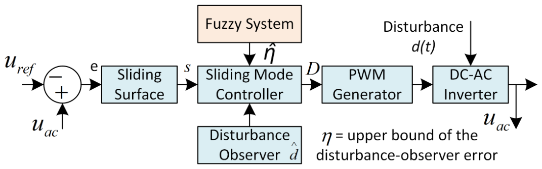
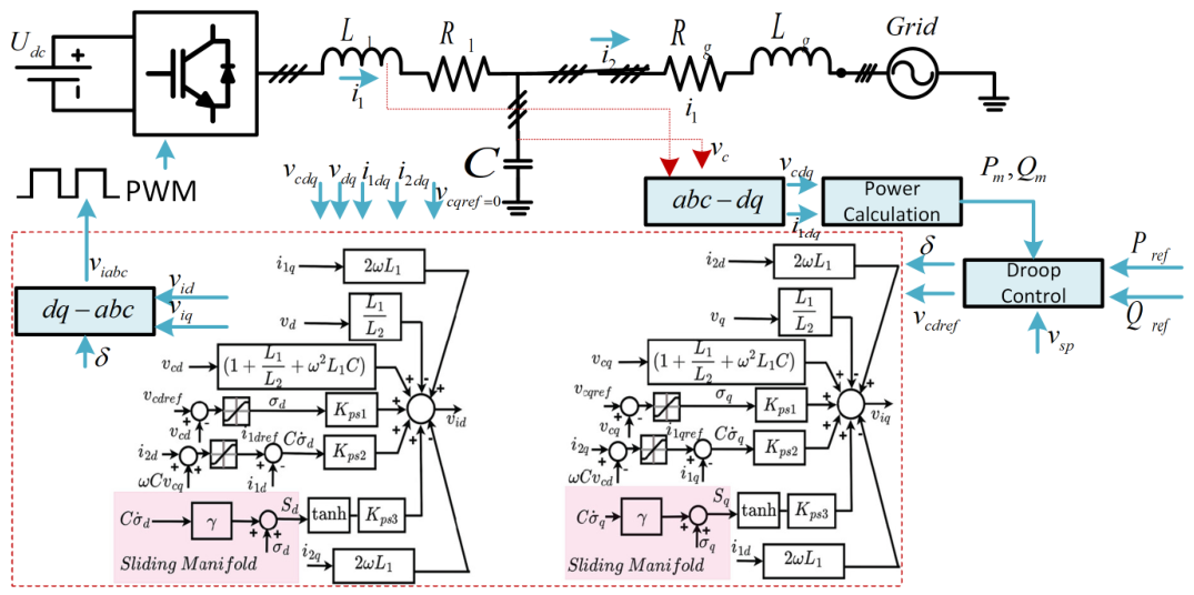
Refs.Research AreaCurrent GapsResearch FocusMaturityMain Challenges
[104]AI-tuned SMCStability proofs
-
Lyapunov/barrier certificates
-
DRL/CNN integration
-
Model compression for FPGA
Early
-
Scalability of formal proofs
-
FPGA memory constraints
-
Real-time inference speed
[153]Forecast-aware SMCForecast uncertainty
-
THD and ramp-rate analysis
-
Sliding-surface uncertainty
-
Forecast-horizon characterization
Pilot
-
Forecast-model accuracy
-
Sensor drift
-
Computational load
[32]PHIL to edge DevOpsDeployment automation
-
Automated PHIL-to-field pipeline
-
Digital-twin validation
-
Live parameter updates
Pilot
-
Secure rollback
-
Firmware synchronization
-
Real-time update risks
[189]Constraint-embedded SMCReactive constraint enforcement
-
IEEE/AS constraint integration
-
Real-time constraint verification
Pilot
-
Non-convex optimization
-
Stability under faults
-
Computational demands
[136]Distributed SMCFleet coordination
-
Gossip-based consensus
-
Delay-tolerant observers
-
Robust distributed control
Concept
-
High communication latency
-
Cybersecurity threats
-
Network scalability
[207]Quantum-classical co-designOptimization efficiency
-
Quantum optimization benchmarking
-
Hybrid optimization strategies
Concept
-
Qubit coherence
-
Latency constraints
-
Limited quantum resources
[42]Cyber-resilient SMCCyberattack robustness
-
Cybersecurity-aware SMC
-
Real-time intrusion detection
Concept
-
Detection of stealth intrusions
-
Computational overhead
-
Security–performance balance
[54]Thermal-aware SMCThermal management
-
Thermal-integrated control
-
Feedback loops for thermal limits
Pilot
-
Thermal-modeling errors
-
Power-quality trade-offs
-
Real-time thermal computations
Disclaimer/Publisher’s Note: The statements, opinions and data contained in all publications are solely those of the individual author(s) and contributor(s) and not of MDPI and/or the editor(s). MDPI and/or the editor(s) disclaim responsibility for any injury to people or property resulting from any ideas, methods, instructions or products referred to in the content.