1. Introduction
The increasing electrification of aircraft systems has led to the development of the so-called more-electric aircraft concept, in which many traditionally hydraulic or mechanical subsystems are replaced by electrically powered devices. As a result, this approach significantly increases the importance of electronic converters in on-board power systems, as they enable efficient conversion, distribution, and control of energy between different subsystems [
1,
2,
3,
4].
Aircraft electrical networks typically operate at a frequency of 400 Hz. Compared to conventional power systems operating at 50 Hz or 60 Hz, higher frequency grids enable a significant reduction in the size and weight of magnetic components such as transformers and inductors. These advantages are particularly important in aviation applications, where minimizing weight and volume is a key design objective [
5,
6]. However, the higher operating frequency also introduces additional challenges to the control of electronic power converters. Because the period of a 400 Hz signal is only 2.5 ms, synchronization algorithms must provide accurate phase and frequency estimation with very short response times. Even small synchronization delays can significantly degrade the performance of current and power control loops.
Accurate synchronization between the power converters and the electrical network is typically achieved using phase-locked loop (PLL) algorithms. PLL structures allow real-time estimation of the phase angle and frequency of periodic signals and, therefore, play a fundamental role in grid-connected power electronic systems. In such applications, synchronization errors can lead to instability or poor power quality, particularly under conditions such as harmonic distortion, voltage imbalance, or frequency variations [
7].
Among various PLL implementations, the synchronous reference frame PLL (SRF-PLL) is one of the most widely used synchronization methods. As a result, the measured voltage is transformed into a rotating reference frame using the Park transformation, and the quadrature component is used as an error signal to control the estimated phase. Consequently, it provides good steady-state accuracy and relatively simple implementation, which has contributed to its widespread adoption in grid-connected converter systems [
8].
Despite its widespread adoption, the SRF-PLL exhibits several limitations under distorted grid conditions, frequency deviations, and rapidly varying operating scenarios, which are particularly relevant in high-frequency aircraft electrical systems [
7]. In response to these limitations, numerous advanced synchronization techniques have been proposed in recent years, including second-order generalized integrator PLLs (SOGI-PLLs), frequency-locked loop (FLL) structures, adaptive observer-based methods, and gradient-based frequency estimation algorithms [
9,
10,
11,
12]. These approaches typically improve harmonic rejection or dynamic tracking performance; however, they often introduce additional computational complexity, require extensive parameter tuning, or remain primarily optimized for conventional 50/60 Hz grid applications. Such limitations reduce their practical suitability for embedded real-time implementations in aircraft power systems, where deterministic timing and low computational latency are critical.
Parallel with the development of advanced synchronization algorithms, significant research efforts have focused on improving current control strategies in grid-connected converters. One of the most widely used approaches to AC current control is the proportional resonant controller (PR) [
13,
14]. Unlike conventional proportional–integral controllers, which are designed primarily for DC signals, PR controllers provide theoretically infinite gain at a selected resonant frequency, allowing accurate tracking of sinusoidal reference signals with zero steady-state error.
Furthermore, PR controllers have become a popular solution for current control in stationary reference frames for grid-connected converters and renewable energy systems. However, their performance strongly depends on the accuracy of the resonant frequency parameter. When the actual system frequency deviates from the nominal value, the controller’s performance can suffer significantly.
To address this issue, recent research has investigated adaptive control structures in which the resonant frequency of the PR controller is continuously updated using frequency estimates obtained from synchronization algorithms. Such approaches allow the control system to maintain optimal performance even under varying operating conditions [
15,
16].
Another important trend in modern power electronics is the increasing use of predictive control concepts. Adaptive control techniques aim to anticipate future system behavior and adjust control actions accordingly, leading to faster transient response and improved dynamic performance [
17,
18]. However, classical model predictive control algorithms often require significant computational resources and detailed system models, which may limit their applicability in real-time embedded implementations.
An alternative approach consists of predictive characteristics indirectly through fast adaptive synchronization combined with dynamically tuned controllers. When the control system can rapidly estimate the instantaneous phase and frequency of the network voltage, it becomes possible to generate current references and control signals that effectively anticipate variations in network conditions [
19,
20]. This is particularly relevant in high-frequency electrical systems such as aircraft power networks, where synchronization delays must be minimized to maintain stable operation. In such systems, adaptive PLL algorithms combined with resonant current controllers may provide a practical solution to achieve adaptive power control with relatively low computational complexity [
21,
22].
Several adaptive synchronization techniques have been reported in the literature to improve the dynamic performance of conventional PLL structures. An important research direction involves adaptive bandwidth PLLs, in which the proportional and integral gains are dynamically adjusted to improve transient performance during frequency disturbances [
23]. Another widely investigated group includes frequency-locked loop (FLL)-based synchronization methods, particularly SOGI-FLL structures, which provide improved harmonic rejection and frequency adaptation capabilities [
10]. More advanced observer-based synchronization techniques have also been proposed, in which adaptive observers are used for the simultaneous estimation of phase, frequency, and signal components under distorted operating conditions [
24].
Although these approaches provide improved synchronization performance, they often introduce additional computational complexity due to adaptive gain scheduling mechanisms, resonant filtering stages, or observer-based state estimation. Such complexity may become problematic in high-frequency aircraft electrical systems, where control latency must be minimized due to the short period of the 400 Hz voltage waveform.
In contrast to existing adaptive PLL approaches, the method proposed in this paper employs a simplified adaptive frequency estimation mechanism based on direct quadrature error processing combined with a lightweight feedforward compensation term. The proposed algorithm does not require PI loop filters, SOGI structures, adaptive observers, or matrix-based estimators. The primary contribution of this work is, therefore, not the introduction of a fundamentally new PLL principle, but rather the development of a low-complexity adaptive synchronization method specifically optimized for FPGA implementation in high-dynamic 400 Hz aircraft power systems. The proposed approach integrates an adaptive PLL algorithm with a proportional resonant current controller to achieve accurate synchronization and dynamic power control. The adaptive PLL continuously estimates the instantaneous phase, frequency, and amplitude of the network voltage, allowing real-time adjustment of the resonant controller parameters. To the best of the authors’ knowledge, similar low-latency adaptive synchronization structures have not been widely investigated for aircraft electrical systems operating at 400 Hz.
The proposed method does not introduce a completely new PLL topology, since the Park transformation and the q-axis error processing are well established in synchronization systems. Instead, the novelty of this work lies in three specific aspects. A simplified adaptive frequency estimation law with feedforward compensation is introduced to improve the transient response under rapid frequency variations. The synchronization algorithm is directly integrated with an adaptive PR-based power control loop, enabling implicit anticipatory behavior without the computational burden of model predictive control. The complete solution is specifically designed for high-frequency 400 Hz aircraft electrical systems, where synchronization constraints are significantly stricter than in conventional 50/60 Hz grids. Therefore, the contribution of this paper is primarily system-level and application-oriented, supported by algorithmic simplifications that enable efficient FPGA implementation.
The structure of the paper is organized as follows.
Section 1 presents the theoretical background of the synchronization algorithms used in grid-connected converters.
Section 2 describes the system model and control structure of the on-board converter and introduces the adaptive frequency estimation algorithm used in the proposed PLL.
Section 3 discusses the implementation aspects of the algorithm in FPGA-based control systems.
Section 4 presents the results of the simulation and performance evaluation under various operating conditions. Finally,
Section 5 concludes the article.
2. Materials and Methods
2.1. Overview of the System
The study presented in the paper concerns adaptive power control in an on-board power converter operating in a 400 Hz electrical network. Such networks are widely used in on-board electrical power systems due to their favorable power-to-weight ratio and reduced size of passive components compared to conventional 50/60 Hz systems. In modern aircraft electrical architectures, on-board power converters are responsible for interfacing various subsystems with the primary power distribution network. These converters must operate reliably under dynamic operating conditions while maintaining strict requirements regarding power quality, synchronization accuracy, and dynamic response.
The control of active and reactive power exchanged between the converter and the on-board grid requires precise estimation of the fundamental component of the grid voltage. In particular, real-time knowledge of the instantaneous phase and frequency is essential for the implementation of synchronous control strategies.
In the presented work, adaptive power control is achieved through the integration of a developed adaptive phase-locked loop (PLL) with a proportional resonant (PR) control system. The proposed PLL provides a real-time estimation of the phase, frequency, and amplitude of the fundamental voltage component. These estimates are subsequently used to control converter currents and achieve the desired power exchange.
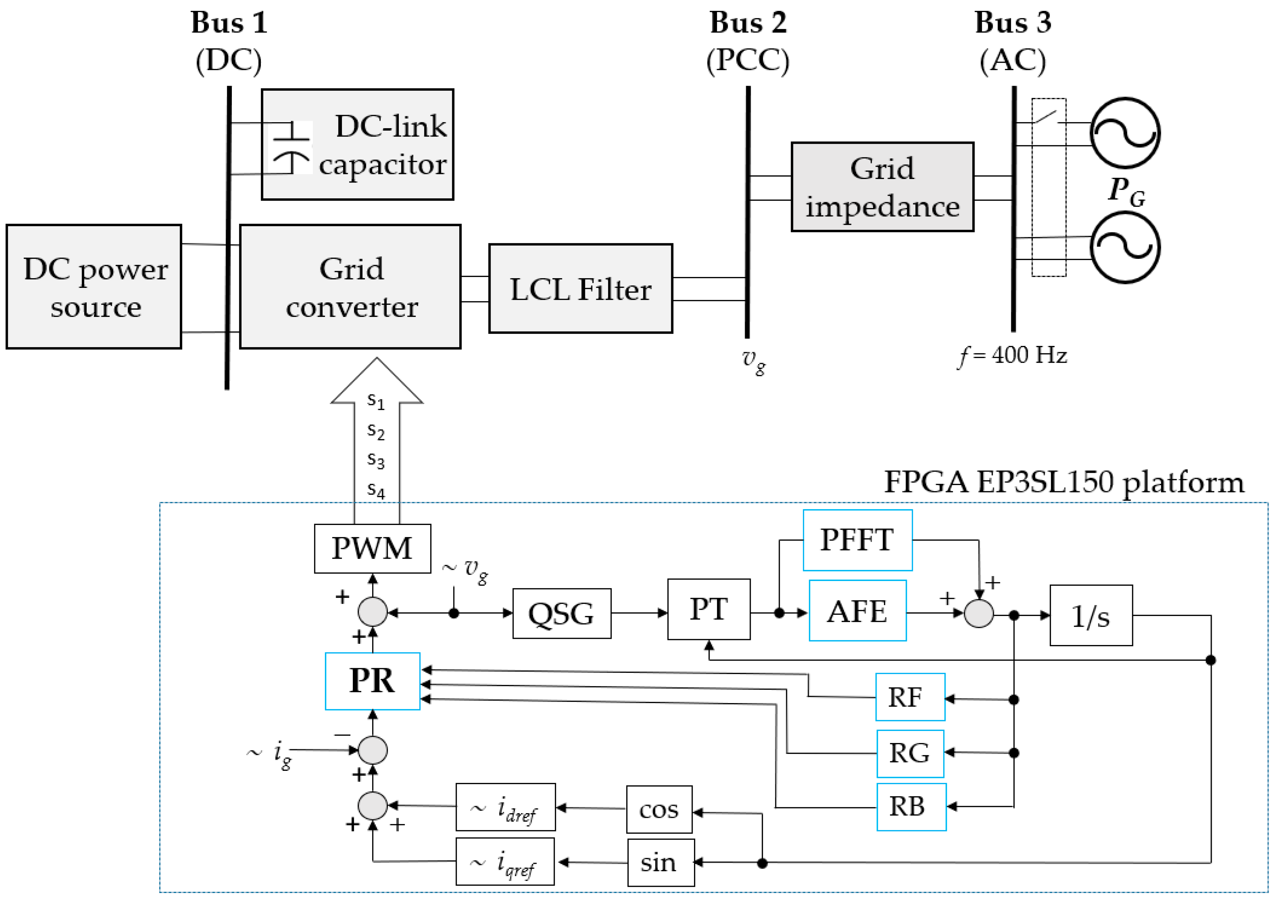
Figure 1 presents the block diagram of the investigated control structure, where the newly introduced components are highlighted in blue. The diagram illustrates the interactions between individual control subsystems, where PR denotes the proportional–resonant controller, QSG represents the quadrature signal generator, PT refers to the Park transformation block, AFE denotes the adaptive frequency estimator, PFFT represents the predictive feedforward term, RF is the resonant frequency calculation block, RG denotes the resonant gain calculation block, and RB represents the resonant bandwidth calculation block. The parameter adaptation process performed by the
RF,
RG, and
RB blocks requires synchronized updating of the PR controller coefficients to ensure stable operation under varying grid conditions. In this work, these blocks are presented as functional elements of the overall control architecture, while the detailed implementation of their internal tuning algorithms is treated as a separate design layer.
The proposed approach enables adaptive behavior without requiring computationally intensive model predictive control (MPC). Instead, adaptive and anticipatory response characteristics emerge from fast synchronization combined with dynamic tuning of the PR controller. The adaptive behavior of the PLL arises from the frequency update law ω[n + 1] = ω[n] + kωq[n], where the quadrature component q[n] reflects instantaneous phase error. This formulation allows for continuous adjustment of the estimated frequency in response to deviations between the input signal and the internal oscillator.
2.2. Characteristics of the 400 Hz Power System
Electrical power systems differ significantly from conventional grids. One of their key features is the operating frequency of 400 Hz. Higher frequencies enable substantial reduction in the size and weight of transformers, filters, and other passive components. However, it also imposes stricter requirements on control and synchronization algorithms. The period of a 400 Hz signal is only T = 2.5 ms, which requires synchronization algorithms to operate significantly faster than in 50 or 60 Hz systems. Even small estimation delays may lead to noticeable errors in current control and power regulation. In addition, on-board networks are subject to dynamic disturbances caused by variable loads, electronic power interfaces, and variations in generator speed. These conditions require synchronization methods capable of maintaining stability under a rapidly changing frequency and amplitude. Consequently, conventional synchronization techniques may exhibit insufficient dynamic performance, which motivates the development of faster and more adaptive PLL structures.
2.3. Adaptive Power Control Structure
The proposed control system regulates the active power exchanged between the converter and the electrical network. The strategy is based on the concepts of synchronous reference frames combined with adaptive estimation of the voltage phase and frequency.
The converter current is controlled using a proportional resonance (PR) regulator operating in the stationary reference frame. The PR controller is particularly well-suited for sinusoidal reference tracking because it provides theoretically infinite gain at the resonant frequency corresponding to the fundamental component of the signal.
The transfer function of the proportional–resonant controller can be expressed as
where
Kp is the proportional gain,
Kr is the resonant gain, and ω
0 represents the angular frequency of the fundamental component of the network voltage.
Unlike conventional implementations, ω0 is not fixed, but is continuously updated using the adaptive PLL frequency estimate. Dynamic tuning ensures that the controller remains aligned with the fundamental component even under frequency variations. As a result, accurate current tracking is maintained. The interaction between adaptive synchronization and resonant control introduces implicit predictive behavior. Since the PLL provides fast frequency and phase estimation, the controller compensates for deviations before a significant phase error develops. The term implicit predictive behavior refers to the ability of the control system to anticipate variations of the grid signal without explicitly solving an optimization problem, as in Model Predictive Control (MPC). In the proposed approach, implicit predictive properties arise from the following two mechanisms:
Fast adaptive frequency estimation: The PLL dynamically updates the estimated frequency based on the quadrature error signal, reducing phase lag.
Dynamic tuning of the PR controller: The resonant frequency is continuously adjusted using the estimated frequency, ensuring alignment with the fundamental component.
As a result, the controller responds to changes in the input signal before significant phase errors accumulate, thereby enabling implicit predictive behavior to be emulated without the need for a system model or future state optimization.
2.4. Role of the Adaptive PLL in the Control Loop
The adaptive PLL plays a central role in the control structure by estimating phase, frequency, and amplitude. These quantities are used for the following:
Synchronization of converter currents with grid voltage;
Dynamic tuning of the PR controller;
Reconstruction of the fundamental component for feedforward control.
The frequency adaptation is based on the quadrature component of the Park transformation, which encodes the phase error. Consequently, fast convergence and high robustness can be achieved. The tight coupling between the PLL and the PR controller forms the basis of the adaptive and implicit predictive behavior of the system.
2.5. Signal Model and Transformation
The input signal is modeled as:
where A is the amplitude,
is phase,
is angular frequency,
and
are the amplitudes and phases of the
h-th harmonic, and
n(
t) represents noise. The model presented is general enough to represent grid voltages, power electronics outputs, or communication carriers. In practice,
A(
t) and ω
in(
t) may vary slowly or rapidly, and the system must track both parameters in real time. For single-phase signals, an orthogonal signal
y[
n] is generated, forming the vector:
The Park transformation yields the following:
The Park transformation enables the separation of synchronization and amplitude dynamics. The quadrature component q[n] is used as the synchronization error signal for frequency adaptation, while the direct component d[n] is used for amplitude estimation.
2.6. Adaptive Frequency Estimation
The primary goal of adaptive PLL is to generate a frequency estimate ω[
n] that rapidly converges to the true input frequency ω
in[
n] while ensuring fast convergence, stability, and robustness. In the d-q frame, the quadrature component
q[
n] encodes the frequency error:
Frequency adaptation is provided by:
where
kω is the loop gain coefficient that determines the adaptation rate, chosen to balance speed and overshoot. Equation (7) avoids nonlinear operations and is suitable for FPGA implementation.
To improve the dynamic response, a feedforward term is introduced:
yielding the updated frequency estimate:
The feedforward term improves transient response during rapid frequency variations while preserving low computational complexity.
2.7. Phase Tracking
Phase tracking is the core function of any phase-locked loop. Its goal is to generate an internal phase
θ[
n] that corresponds to the phase of the input signal
θin[
n]. The phase is updated using:
The precision of
θ[
n + 1] depends on the length of the word in fixed-point arithmetic. Finite resolution can introduce quantization errors that accumulate as phase drift. The sampling interval
Ts determines the step size of the phase update; smaller
Ts reduces the phase error but increases the computational load. Accurate phase tracking relies on accurate ω[
n + 1], and as a consequence, errors in frequency estimation manifest themselves as linear phase drift over time. Assuming small phase error
, the update law can be linearized:
where
kω is the loop gain of the frequency adaptation law. Linearization yields a first-order discrete-time system with eigenvalue 1 −
kωTs. As a consequence, an overdamped response can be obtained for 0 <
< 1, convergence rate directly controlled by
, and predictable settling time, critical for real-time systems. The synchronized output sinusoid is reconstructed as
with amplitude
A[
n] estimated separately. The reconstructed signal follows the fundamental component of the input waveform in steady-state operation.
2.8. Amplitude Estimation
The amplitude of the input sinusoidal signal is a critical parameter for reconstruction and adaptive control. After transformation d-q, the in-phase component
d[
n] aligns with the instantaneous input amplitude, while
q[
n] encodes the frequency/phase error. For small
Thus, the estimation of the amplitude can be performed directly from
d[
n]. A simple first-order low-pass filter is applied to remove high-frequency noise. The amplitude is estimated using:
where
kA is the adaptation coefficient. This avoids costly square root operations while providing smooth and reliable amplitude tracking. The filtered amplitude is subsequently used to scale the reconstructed output sinusoid.
For signals with rapid amplitude modulation, a variable step size improves responsiveness:
Since the estimation of the amplitude is affected by additive noise, harmonics, and phase error coupling at small the advanced strategy to estimate A[n] from the magnitude of d–q vector is proposed.
The comparative analysis of the amplitude estimation methods considered is presented in
Table 1.
A first-order low-pass estimator was selected in the final implementation due to its low computational complexity and sufficient accuracy for the considered 400 Hz on-board application. More advanced amplitude estimation methods were not implemented because they would increase hardware complexity without providing significant improvement under the analyzed operating conditions.
2.9. Stability Considerations
The closed-loop dynamics of the adaptive PLL can be approximated as a second-order linear system.
The stability condition is as follows.
Empirically,
kωTs ≈ 0.2 provides a trade-off between fast convergence and minimal overshoot. As a result, an overdamped response and stable convergence are achieved [
25,
26].
3. Implementation in FPGA
The proposed adaptive PLL algorithm is well-suited for implementation on reconfigurable hardware platforms due to its relatively low computational complexity and inherently parallel structure. Field-programmable gate arrays (FPGAs) offer deterministic timing, low latency, and efficient pipelining capabilities, making them particularly suitable for real-time signal processing tasks such as frequency estimation and phase tracking.
The overall FPGA architecture follows the signal processing chain described in previous sections. The system processes the sampled input signal x[n] at a fixed sampling frequency fs, and performs orthogonal signal generation, coordinate transformation, and adaptive estimation of frequency, phase, and amplitude in real time.
The implementation consists of the following functional blocks:
Orthogonal signal generation;
Park transformation;
Phase detector (q-component extraction);
Adaptive frequency estimation unit;
Phase accumulator (numerically controlled oscillator, NCO);
Amplitude estimation block;
Sinusoidal signal reconstruction.
These modules are arranged as a synchronous processing pipeline. Each block operates on sampled data and passes the results to the next stage through register-based interfaces, enabling high-throughput operation. The pipeline structure ensures that all computations are completed within a single sampling period, which is essential for maintaining real-time performance in a 400 Hz system. To ensure efficient hardware use, the entire system is implemented using fixed-point arithmetic. Key design choices include the following:
Internal variables such as: d[n], q[n], A[n], Δω[n], and θ[n] are represented using 16–24 bit fixed-point formats.
The presented approach ensures a good trade-off between numerical accuracy and the utilization of hardware resources. The conversion from phase θ[n] to sinusoidal signals is performed using lookup tables (LUTs).
The precomputed sine and cosine values are stored in memory blocks.
Phase indexing is performed using the most significant bits of θ[n].
Linear interpolation may be applied to improve resolution if necessary.
Parallel processing: All blocks can operate concurrently for minimal latency, crucial for 10 kHz sampling rates.
The developed method eliminates the need for computationally expensive trigonometric operations, significantly reducing latency and logical use.
The proposed architecture fully exploits the FPGA parallelism. Each processing stage operates simultaneously, allowing continuous data flow through the pipeline.
Key features:
As a result, the total processing latency is limited to a few clock cycles, which is significantly smaller than the sampling period.
For a sampling frequency of fs = 10 kHz, the sampling period is Ts = 100 μs. The total computational latency of the FPGA implementation is on the order of a few microseconds, depending on the depth of the pipeline and clock frequency. Unlike MPC, which requires solving an optimization problem at each sampling step, the proposed method relies on recursive update equations, resulting in constant computational complexity. As a result,
All computations are completed before the next sample arrives;
No additional delay is introduced into the control loop;
Synchronization accuracy is preserved.
Unlike MPC, which requires solving an optimization problem at each sampling step, the proposed method relies on recursive update equations, resulting in constant computational complexity. Low and deterministic latency is particularly critical in 400 Hz systems, where phase errors accumulate rapidly.
The proposed algorithm is computationally lightweight and does not require complex operations such as division, matrix inversion, or iterative optimization. Typical FPGA resource usage includes the following:
Adders and multipliers for arithmetic operations;
Registers for pipeline storage;
Block RAM for lookup tables;
Control logic for synchronization and saturation.
Compared to model predictive control (MPC), the proposed implementation:
Requires significantly fewer arithmetic operations;
Avoids iterative solvers;
Reduces memory usage;
Enables higher clock frequencies.
Consequently, the solution is particularly suitable for embedded and resource-constrained systems.
Several optimizations were applied to improve performance.
The implemented design utilized approximately 18% of the logic elements, 12 DSP blocks, and 9% of the available memory resources of the target FPGA platform. The maximum operating frequency exceeded 85 MHz, while the total computational latency remained below 8 μs, which is significantly lower than the sampling period of 100 μs. These results confirm the suitability of the proposed algorithm for real-time on-board applications.
4. Real-Time Validation and Experimental Results
4.1. Test Setup
The performance of the proposed adaptive phase-locked loop (PLL) was evaluated through a series of simulation studies designed to assess the robustness, precision, and dynamic response under realistic operating conditions. The simulations were carried out using a discrete-time model of the entire signal processing chain, including the Park transformation, adaptive frequency estimation, phase tracking, and amplitude estimation blocks. Research methodology consists of analytical formulation, simulation-based validation, implementation of an FPGA, and comparative evaluation with conventional synchronization methods. It should be emphasized that the presented validation was performed using a Rapid Control Prototyping (RCP) platform operating under real-time hardware constraints. Therefore, the obtained results include practical implementation effects such as sampling delays, quantization effects, and execution latency. The FPGA experiments presented later constitute the final validation stage.
The input signal was sampled at a frequency of fs = 10 kHz, corresponding to a sampling period of Ts = 100 μs. The nominal input frequency was set to f0 = 400 Hz with the corresponding angular frequency ω0 = 2513.27 rad/s. The adaptive frequency update law is defined as ω[n + 1] = ω[n] + kωq[n], while the phase update follows θ[n + 1] = θ[n] + ω[n]Ts. The estimation of the amplitude is given by A[n + 1] = A[n] + kA(d[n]−A[n]). All simulations were performed using fixed-point arithmetic consistent with the target FPGA implementation.
The following test scenarios were considered:
Each experiment evaluates a different aspect of the algorithm and demonstrates its suitability for real-time signal synchronization.
4.2. Response to Frequency Steps
The dynamic response of the PLL to abrupt frequency changes was evaluated using the following step profile:
The presented scenario reflects typical disturbances of the power system caused by load or generation.
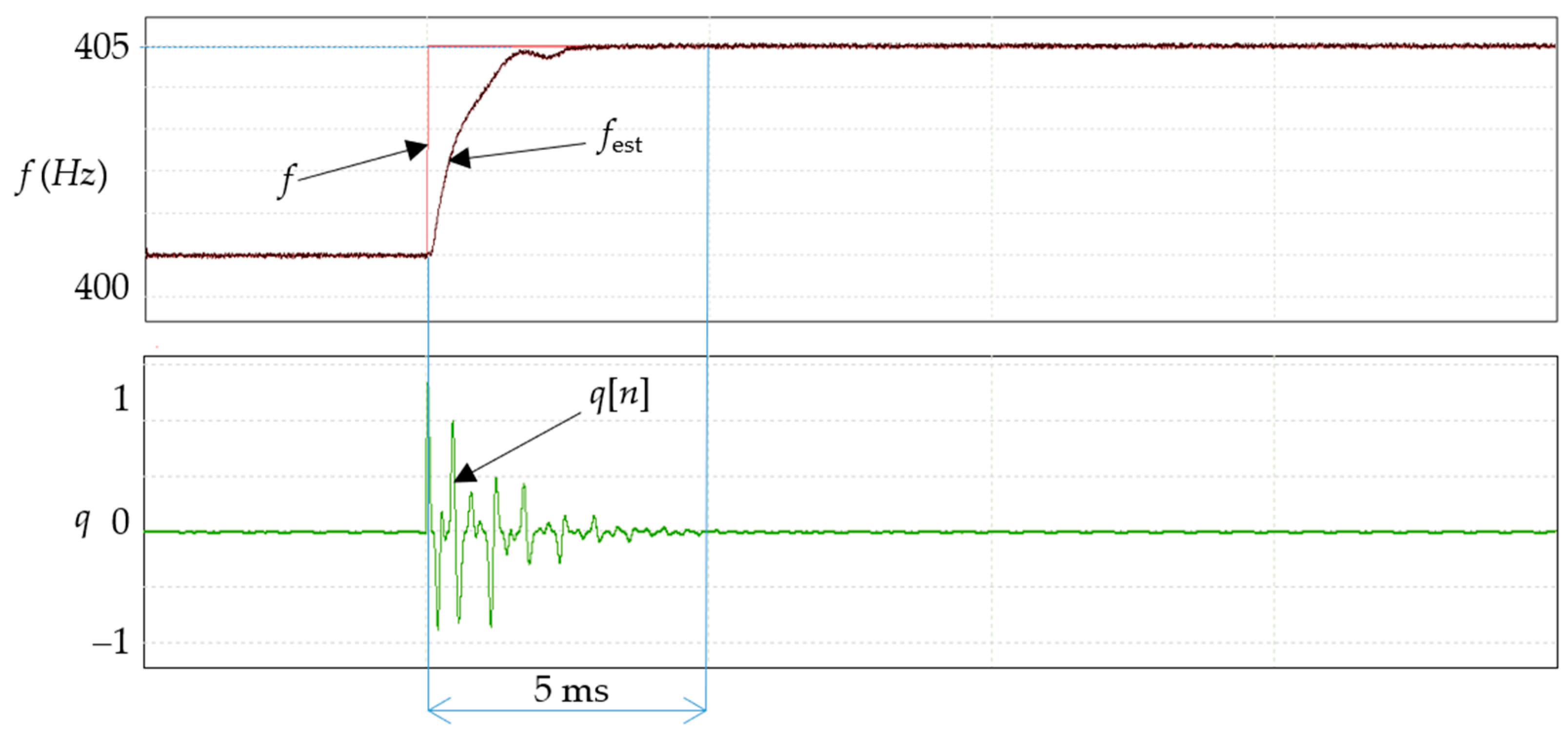
As shown in
Figure 2, the proposed PLL rapidly converges to the new frequency value. The quadrature component q[n] increases immediately after disturbance and drives the frequency adaptation mechanism.
The observed settling time is approximately one fundamental period (~2.5 ms), which confirms the fast dynamic response of the proposed method. The overshoot is negligible, and the steady-state frequency error approaches zero.
4.3. Frequency Ramp Tracking
To evaluate the tracking under continuously varying conditions, a linear frequency ramp was applied:
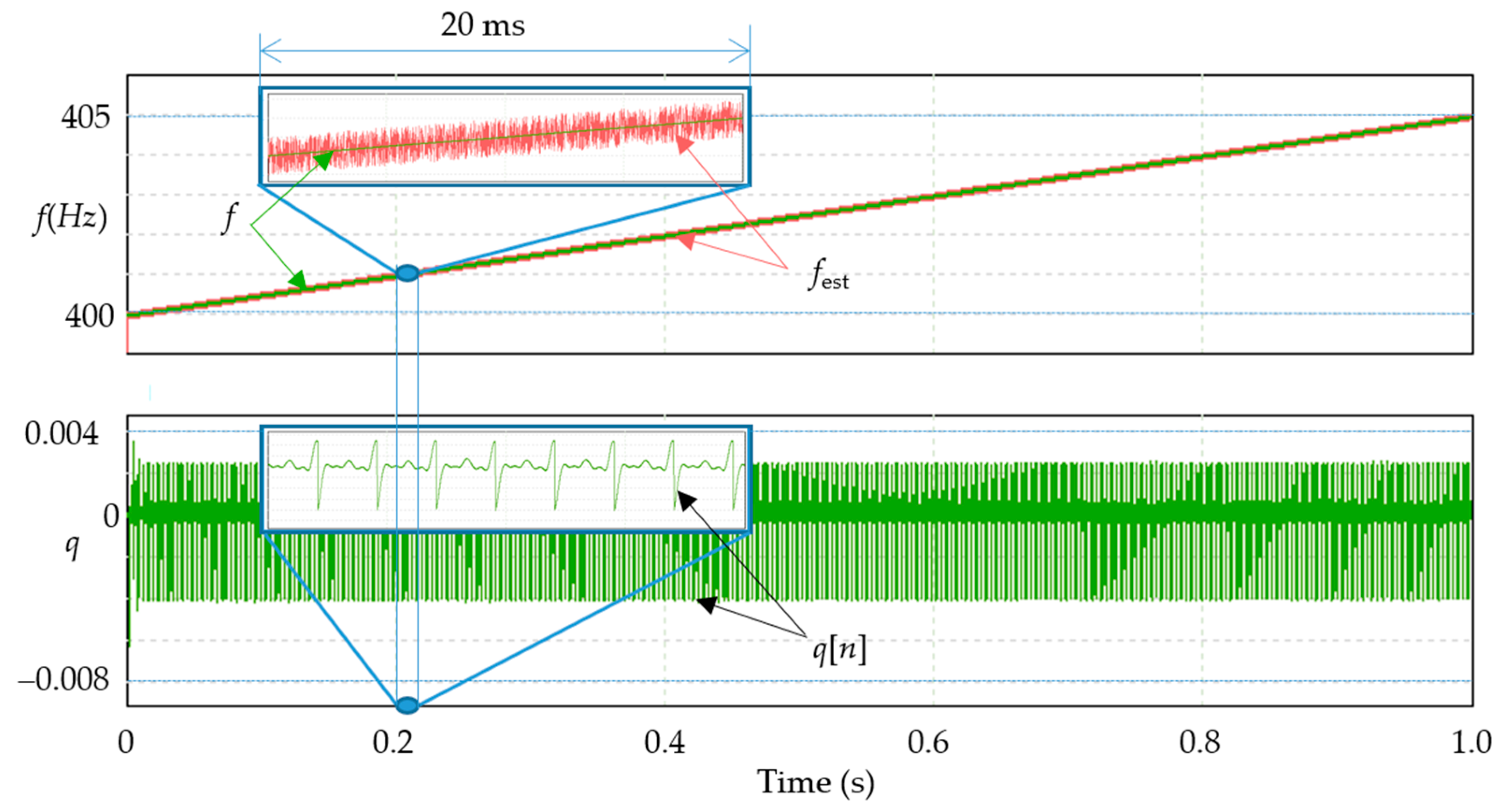
representing a frequency increase from 400 Hz to 405 Hz in one second.
Figure 3 shows that the estimated frequency closely follows the true signal.
The instantaneous tracking error
remains small throughout the experiment, confirming stable operation under dynamic conditions. The results indicate that the algorithm maintains synchronization without phase loss even during continuous frequency variation.
4.4. Harmonic Distortion Test
To evaluate robustness under non-ideal conditions, the input signal was defined as:
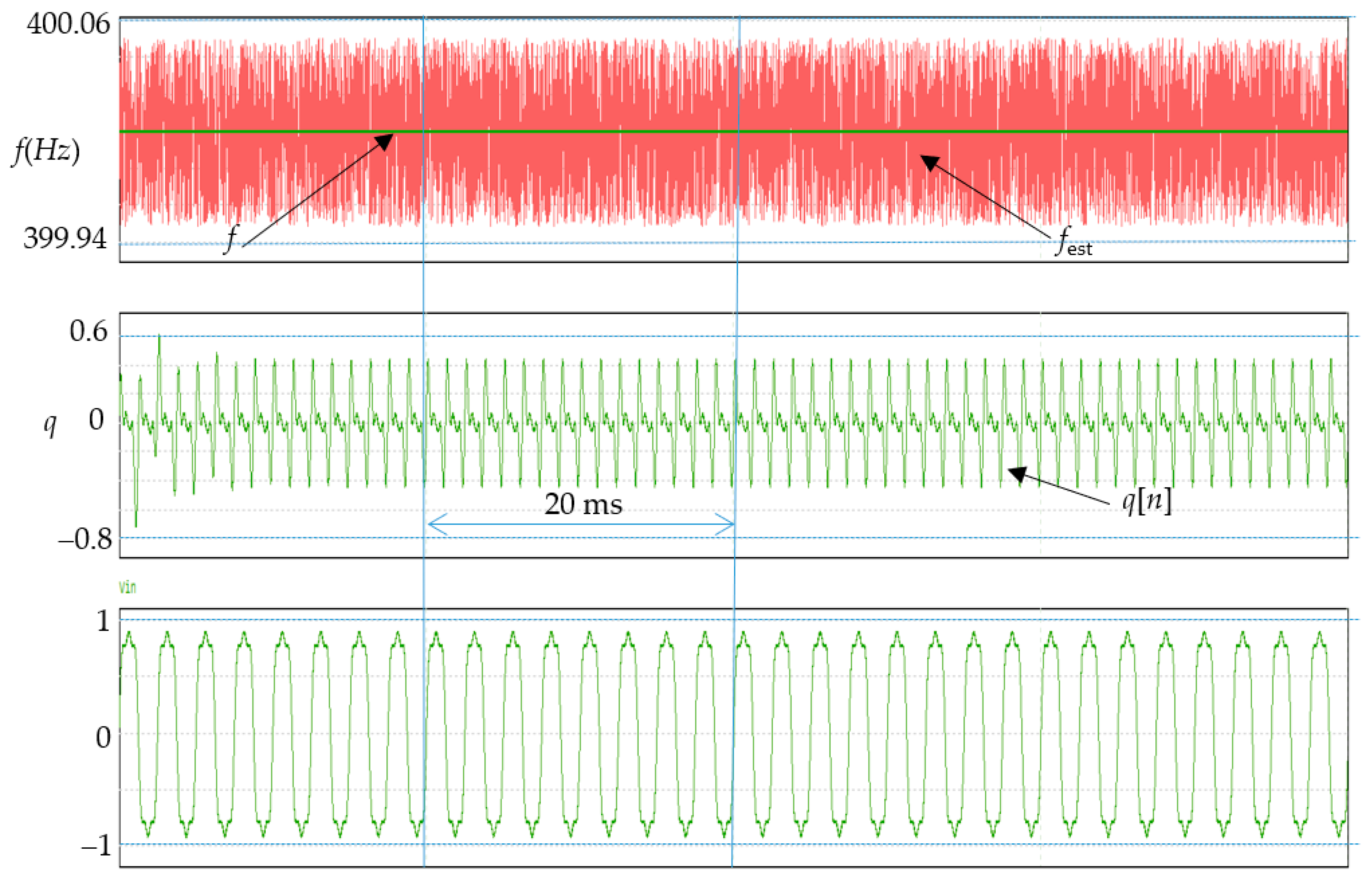
Equation (23) corresponds to 20% third harmonic and 10% fifth harmonic distortion. Such distortion levels are typical in power systems with nonlinear loads.
Despite the significant harmonic content, the PLL maintains stable operation and accurately estimates the fundamental frequency, as shown in
Figure 4.
The robustness is primarily due to the following:
The Park transformation, which isolates the fundamental component.
The adaptive filtering inherent in the frequency update loop.
The results confirm a strong immunity to harmonic distortion.
4.5. Noise Robustness
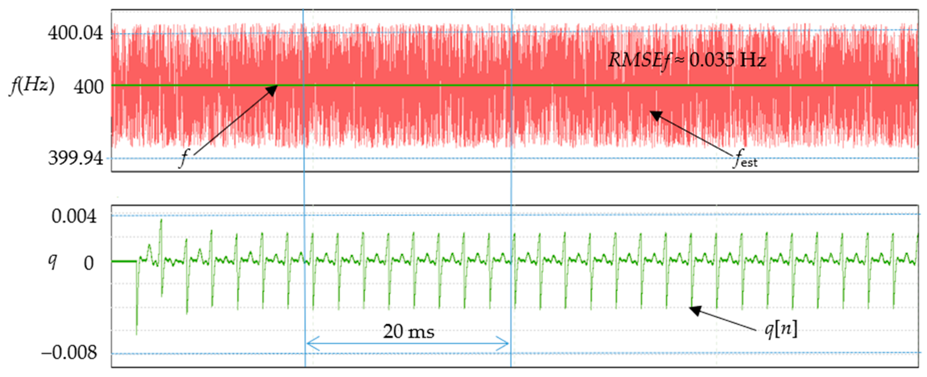
White Gaussian noise was added to the input signal with SNR levels of 40 dB, 30 dB, and 20 dB. Although the quadrature signal becomes increasingly noisy, the estimated frequency remains stable due to the low-pass characteristics of the adaptive loop, as shown in
Figure 5.
Estimation accuracy was quantified using the RMSE.
RMSE was calculated on N = 4000 samples under steady-state conditions. Even at SNR = 20 dB, the frequency error remains low, demonstrating robustness suitable for practical measurement environments.
4.6. Sensitivity Analysis of Adaptive Parameters
The performance of the proposed PLL is strongly dependent on the adaptive coefficients kω and kff. Therefore, an additional sensitivity analysis was conducted to evaluate their influence on synchronization performance. Coefficient values were selected heuristically. Three values of kω were tested as follows:
Low gain: slow convergence (kωTs = 0.1);
Nominal gain (kωTs = 0.2);
High gain: faster response but increased overshoot (kωTs = 0.5).
The observed results showed that increasing kω reduced the settlement time from 4.8 ms to 1.9 ms, while excessive gain introduced oscillatory behavior.
Similarly, the feedforward coefficient kff was varied from 50 to 300 to analyze transient performance during frequency steps.
Moderate values of kff improved the transient response by reducing phase delay by approximately 18%, while excessively high values amplified the noise sensitivity.
The results confirm that proper tuning of adaptive parameters is required to balance dynamic performance and robustness. However, detailed research and results will be presented in a future paper.
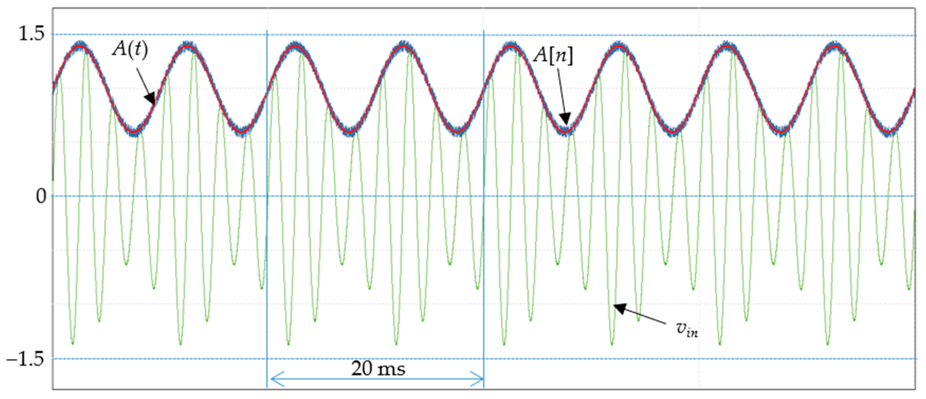
4.7. Tracking of Amplitude Variation
The amplitude tracking was evaluated using the following:
The results (
Figure 6) show that the estimated amplitude accurately follows the true signal with minimal delay.
Additionally, the reconstructed signal: remains well-aligned with the fundamental component, confirming correct joint estimation of amplitude and phase.
4.8. Discussion
The simulation results demonstrate that the proposed adaptive PLL provides the following:
Fast convergence (within one signal period);
High steady-state accuracy;
Robustness to harmonics and noise;
Reliable amplitude tracking.
These properties make the algorithm suitable for real-time applications in power electronics and grid synchronization, particularly in high-frequency systems. The validation presented was limited to single-converter operation. Future studies should investigate multiconverter coordination, communication constraints, and operation under severe electrical disturbances.
4.9. Comparison with Conventional PLL Methods
To evaluate the effectiveness of the proposed synchronization algorithm, its performance was compared with two widely used synchronization methods commonly used in power electronics and signal processing applications:
In addition to classical SRF-PLL and SOGI-PLL methods, recent studies have introduced adaptive synchronization techniques based on gradient descent optimization, adaptive observers, and frequency-locked loop structures. These methods often provide improved estimation accuracy under distorted conditions, but frequently require additional computational resources, matrix operations, or observer tuning procedures. Such complexity may limit its applicability in FPGA-based high-speed implementations. The proposed method maintains lower computational complexity by using a direct adaptive update law while preserving a fast dynamic response.
SRF-PLL is one of the most widely used synchronization algorithms in grid-connected converters. It relies on the Park transformation to generate the quadrature error signal, which is then processed by a proportional–integral (PI) controller to estimate the signal phase and frequency. The SOGI-PLL introduces an orthogonal signal generator based on a second-order resonant filter, allowing for accurate extraction of the fundamental component even in the presence of harmonic distortion. Although both approaches provide reliable synchronization, they may suffer from limited dynamic performance when the input frequency varies rapidly.
The proposed algorithm differs from these classical approaches in that it directly adapts the estimated frequency using an adaptive update law driven by the quadrature error signal. The presented structure allows for faster frequency convergence without requiring a classical PI loop filter. All methods were tested under identical conditions (
Table 2).
Each algorithm was tuned to achieve stable operation and comparable steady-state accuracy.
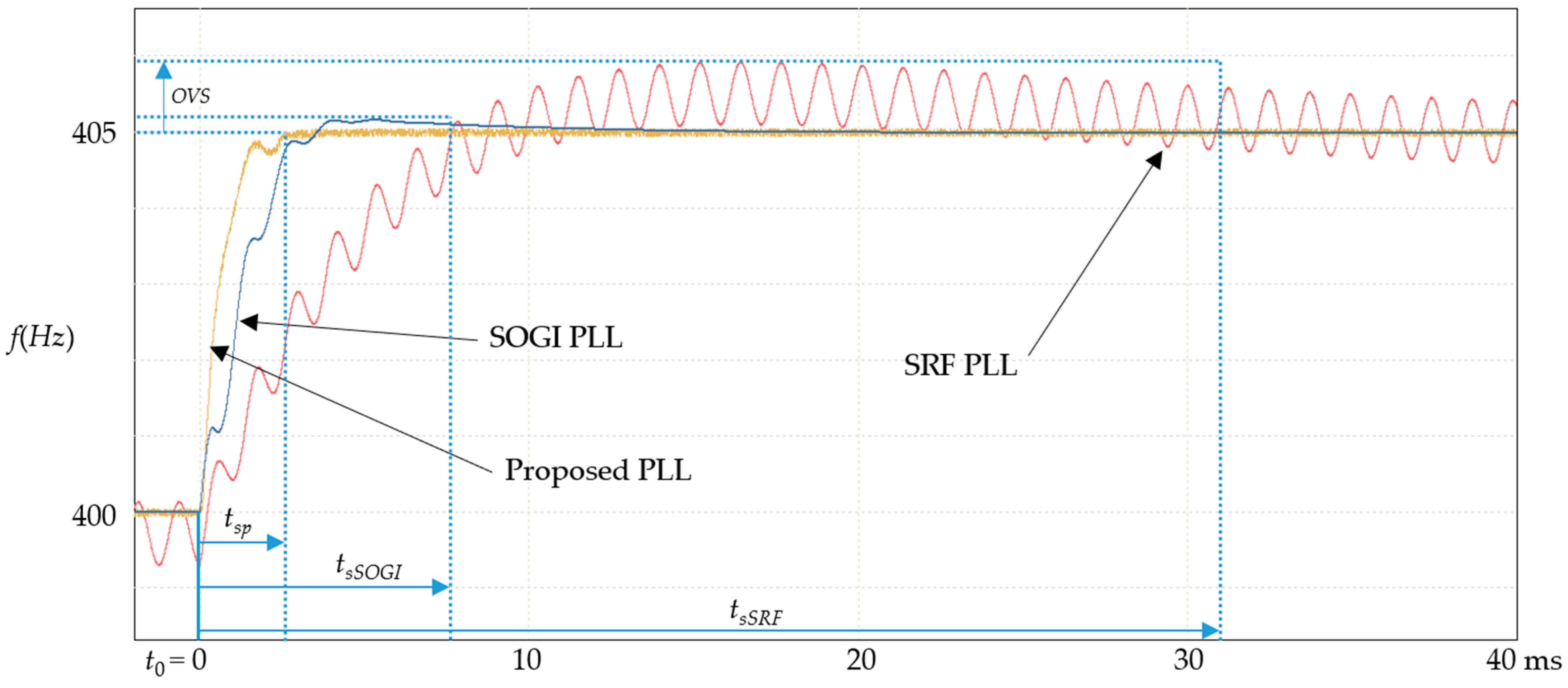
Figure 7 shows the estimated frequency for all three methods when the input frequency changes from 400 to 405 Hz. The SRF-PLL shows a relatively slow response as a result of the dynamics of the PI loop filter.
The proposed PLL achieves the following:
The shortest settling time;
Minimal overshoot;
Comparable steady-state accuracy;
Improved robustness performance.
Unlike SRF-PLL, it does not rely on a PI controller, which eliminates tuning trade-offs between speed and stability. Compared to SOGI-PLL, it achieves faster dynamics while maintaining comparable robustness.
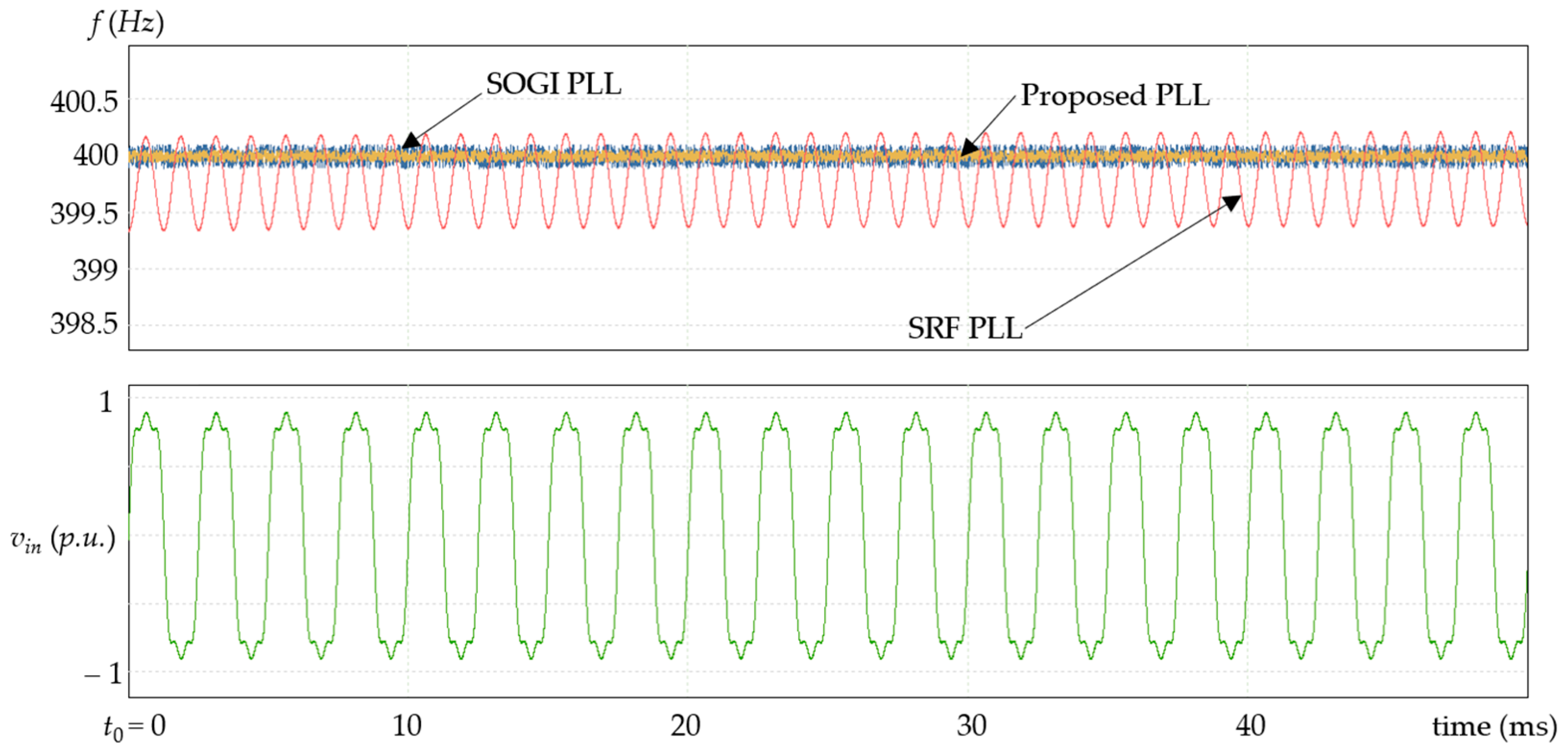
Another important comparison concerns the performance of the synchronization algorithms in the presence of harmonic distortion. In the experiment carried out, the input signal contained both third and fifth harmonic components.
Figure 8 shows the estimated frequency signals calculated by the three algorithms.
The SRF-PLL is particularly sensitive to harmonic distortion because the quadrature error signal contains harmonic components that propagate through the PI controller. As a result, oscillations in the estimated frequency can be observed. The SOGI-PLL performs significantly better in the investigated scenario due to the inherent filtering properties of the resonant structure. However, the presence of harmonics still influences the transient behavior. The proposed algorithm exhibits robustness comparable to or improved over the SOGI-PLL. The adaptive frequency update mechanism naturally filters high-frequency error components, which reduces the influence of harmonic disturbances on the frequency estimate.
Table 3 summarizes the key performance indicators obtained from the simulations performed.
The results clearly indicate that the proposed synchronization algorithm achieves the fastest convergence while maintaining high steady-state accuracy. The comparison results highlight several advantages of the proposed adaptive synchronization method. First, the direct adaptive frequency update law enables faster convergence compared with conventional PLL structures that rely on PI controllers. Second, the algorithm maintains good robustness against harmonic distortion and measurement noise. Finally, the computational complexity of the proposed approach remains relatively low, making it suitable for real-time FPGA implementations. These characteristics make the method particularly attractive for applications that require fast and reliable synchronization, such as grid-connected converters, power electronics systems, and real-time signal processing platforms.
4.10. Hardware Tests
The proposed adaptive control algorithm was validated on an FPGA-based platform. The modular structure refers to the separation of the control system into independent functional blocks, including the following:
Each module can be implemented and optimized independently, simplifying the implementation of the FPGA and enabling parallel execution.
The system operates at
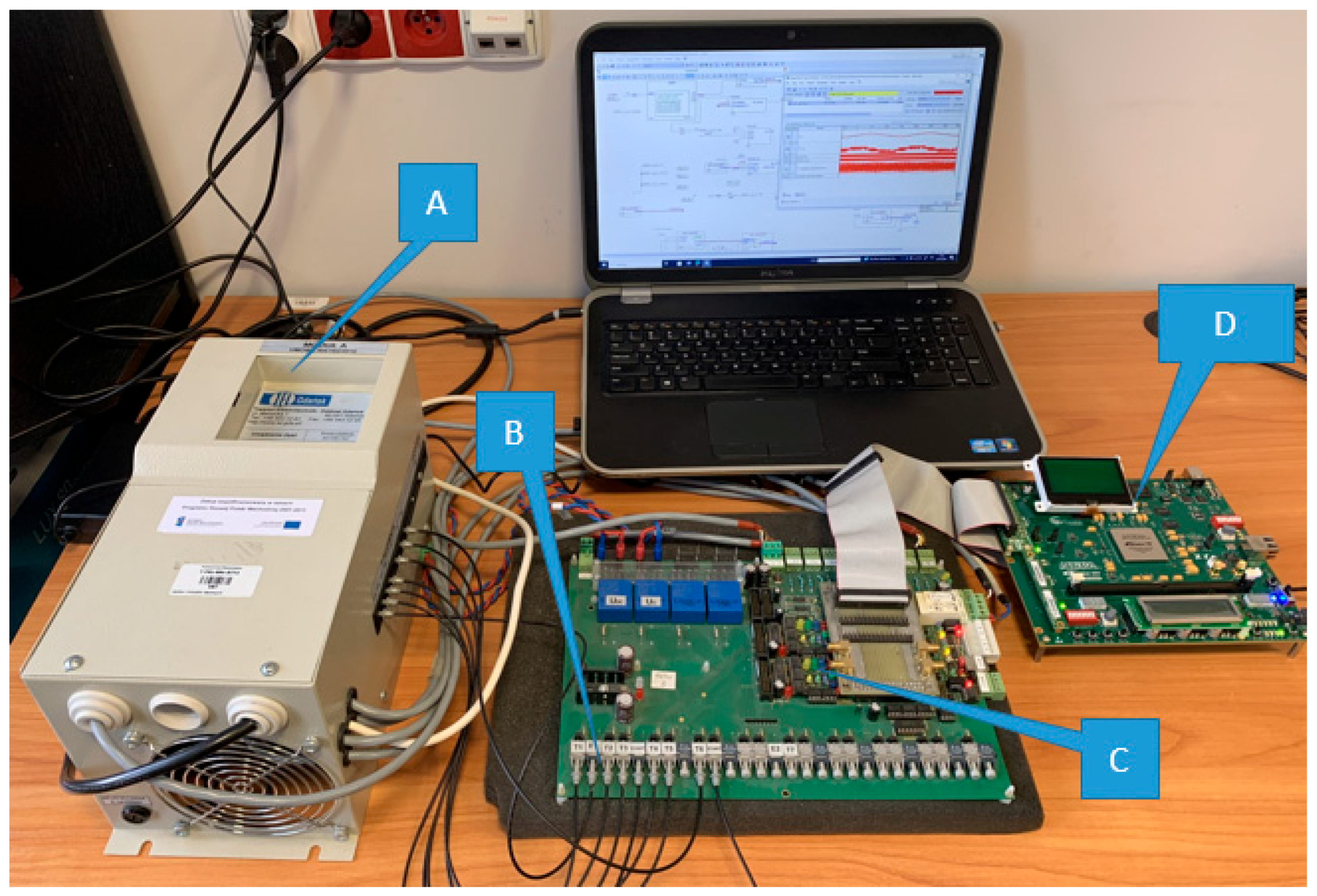
fs = 10 kHz using fixed-point arithmetic and a pipeline architecture. The experimental setup (
Figure 9) consists of the following: A—grid inverter, B—fiber optic coupling, C—main board on-board, D—CPU based on FPGA EP3SL150F1152C2N of the Stratix III family board.
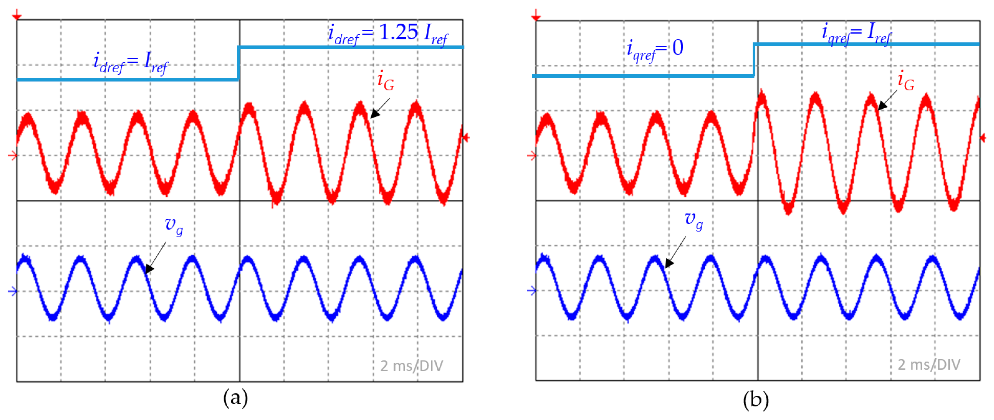
Dynamic performance was evaluated using step changes in active and reactive power. The results (
Figure 10) show the following:
The adaptive PLL enables precise synchronization, which directly translates into accurate current tracking and stable power regulation.
5. Conclusions
The paper presents an adaptive power control strategy for an on-board power converter operating in a 400 Hz aircraft electrical network. The proposed approach integrates an adaptive phase-locked loop (PLL) with a proportional resonant (PR) controller, enabling accurate synchronization and dynamic power regulation under varying operating conditions.
The main contribution of the work lies in the introduction of an adaptive synchronization mechanism that exhibits implicit predictive behavior without relying on explicit model predictive control (MPC). Unlike classical predictive control approaches, the proposed method does not require the discretization of the system model, the optimization of the cost function, or iterative computation. Instead, anticipatory response characteristics emerge naturally from the fast adaptive frequency estimation and dynamic tuning of the resonant controller.
The adaptive PLL continuously estimates the instantaneous phase, frequency, and amplitude of the input signal using a computationally efficient update law driven by the quadrature component of the Park transformation. The presented structure enables fast convergence, low steady-state error, and robustness against disturbances such as harmonic distortion and measurement noise.
The simulation results demonstrate that the proposed method achieves synchronization in approximately one fundamental period, while maintaining high accuracy in frequency steps, ramps, harmonic distortion, and noisy conditions. Compared to conventional SRF-PLL and SOGI-PLL methods, the proposed algorithm exhibits significantly improved dynamic performance while preserving comparable steady-state accuracy.
Experimental validation using an FPGA-based implementation confirms the practical applicability of the proposed approach. Hardware tests demonstrate fast transient response, minimal overshoot, and accurate power control during dynamic operating conditions. The low computational complexity of the algorithm enables efficient real-time implementation using fixed-point arithmetic and pipelined processing structures.
In general, the proposed method provides a favorable trade-off between dynamic performance, robustness, and implementation complexity. These properties make it particularly suitable for high-frequency power systems, such as aircraft electrical networks. The proposed adaptive PLL introduces several important design trade-offs that must be considered in practical implementations.
First, the adaptation gain kω directly affects the convergence speed and stability. Higher gain values lead to a faster response, but may increase sensitivity to noise and induce oscillations. Conversely, lower gain values improve stability at the expense of slower convergence.
Second, the use of feedforward terms enhances dynamic performance but introduces additional sensitivity to the high-frequency components of the error signal. As a consequence the careful tuning or filtering to avoid amplification of the measurement noise is required.
Third, the fixed-point implementation on an FPGA necessitates appropriate scaling and saturation mechanisms to prevent overflow while preserving numerical precision. These constraints influence the achievable resolution of frequency and phase estimation.
Despite these trade-offs, the proposed structure allows intuitive tuning and does not require complex controller synthesis procedures, which is a significant advantage over model-based predictive control methods.
Although the proposed method demonstrates promising performance, several aspects require further investigation.
First, the behavior of the adaptive PLL in multiconverter systems should be analyzed. In practical aircraft power systems, multiple converters may operate in parallel, each performing independent synchronization. Future work will focus on the integration of event-triggered synchronization mechanisms to reduce computational and communication overhead.
Second, more work is needed to quantify the computational efficiency of the proposed method compared to the classical model predictive control algorithms. Consequently, detailed benchmarking in terms of execution time, resource utilization, and energy consumption on FPGA platforms is needed.
Third, the robustness of the algorithm should be investigated under more severe grid disturbances, such as voltage imbalance, frequency discontinuities, and transient faults. Extending the method to three-phase systems and unbalanced conditions is also an important direction.
Another promising research direction involves the incorporation of adaptive filtering techniques or machine learning-based estimators to further improve robustness in highly distorted environments.
Finally, experimental validation on a full-scale hardware platform, including emulation of the real aircraft power system, would provide additional confirmation of the practical applicability of the proposed approach.
Unlike conventional adaptive PLL studies that focus primarily on synchronization accuracy alone, this work demonstrates the integration of adaptive synchronization, adaptive current control, and FPGA implementation within a unified framework dedicated to aircraft electrical systems. Future work will focus on multi-converter coordination and operation under severe grid disturbances.