Abstract
This study presents a comprehensive analysis and optimization methodology for bridge-connected modulators in coaxial magnetic gears. A novel harmonic modeling method incorporating magnetic saturation through permeability convolution matrices and multiple-layer radial subdivision is developed, achieving computational efficiency 20 times greater than finite element analysis with comparable accuracy (deviation < 3.2%). The research establishes an electromagnetic–structural coupling framework that captures the complex interactions between the magnetic field distribution and mechanical deformation, revealing critical trade-offs between electromagnetic performance and structural integrity. Multi-objective optimization using an improved NSGA-II algorithm identifies Pareto-optimal solutions balancing torque density, structural safety, efficiency, and thermal stability. Experimental testing validates that bridge width ratios between 0.05 and 0.07 provide optimal performance, delivering torque densities exceeding 80 kNm/m3 while maintaining stress ratios below 0.65 of material yield strength. Thermal analysis demonstrates that optimized configurations maintain operating temperatures below 70 °C with reduced thermal gradients. Vibration characteristics exhibit a strong correlation with bridge width, with wider bridges providing enhanced stability at higher speeds. The findings establish practical design guidelines for high-performance magnetic gears with improved reliability and manufacturability, advancing the fundamental understanding of electromagnetic–structural interactions in field-modulated magnetic gear systems.
1. Introduction
Magnetic gears have emerged as promising alternatives to conventional mechanical gears due to their inherent advantages, including contactless torque transmission, overload protection, reduced maintenance requirements, and elimination of lubrication [1]. Among various topologies, coaxial magnetic gears (CMGs) have attracted significant attention for their compact structure, high torque density, and excellent efficiency [2]. The operating principle of CMGs relies on the field modulation effect induced by ferromagnetic modulators positioned between the inner high-speed rotor and the outer low-speed rotor. Despite these advantages, the practical implementation of CMGs faces substantial challenges, particularly in the mechanical design and fabrication of the modulator assembly. Conventional modulator structures composed of discrete ferromagnetic segments require sophisticated supporting methods to maintain precise positioning while withstanding high electromagnetic forces. Bridge-connected modulators represent an innovative solution to this manufacturing challenge, where adjacent ferromagnetic segments are joined by thin iron bridges to form an integrated structure. However, these bridges inevitably create magnetic flux leakage paths that adversely affect torque transmission performance. This inherent trade-off between electromagnetic performance and structural integrity necessitates a sophisticated multiphysics approach that considers both electromagnetic and mechanical aspects simultaneously during the design process.
The electromagnetic analysis of CMGs with bridge-connected modulators presents unique challenges due to the complex magnetic field distribution and pronounced saturation effects in the narrow bridge regions. Recent analytical approaches for field-modulated magnetic structures have seen notable advancements. First, modified subdomain-based models incorporating nonlinear permeability characteristics have been proposed to improve accuracy in flux density prediction under saturation conditions [3,4]. Second, enhanced magnetic equivalent circuit (MEC) methods have been developed to account for magnetic flux leakage and nonuniform field distribution in segmented modulators [5,6]. Third, spatial harmonic modeling techniques based on Fourier decomposition have been employed to effectively describe quasi-periodic permeability profiles and their modulation effects [7,8,9]. Despite these advances, traditional analytical methods such as the subdomain method (SDM) often fail to accurately account for the nonlinear B-H characteristics of ferromagnetic materials, particularly in highly saturated bridge sections [10]. While finite element analysis (FEA) can provide accurate results, its computational intensity makes it unsuitable for iterative optimization processes. The harmonic modeling method (HMM) offers a promising alternative by incorporating permeability convolution matrices, yet existing implementations require significant enhancement to properly model bridge-connected structures. Furthermore, the mechanical performance of bridge-connected modulators remains inadequately explored. The bridges are subjected to complex stress distributions arising from electromagnetic forces, centrifugal effects, and thermal expansion, potentially leading to structural failures under operational conditions. A comprehensive electromagnetic–structural coupled analysis is, therefore, essential to properly evaluate performance trade-offs and ensure reliable operation across various working conditions.
Despite extensive research on CMGs, the systematic optimization of bridge-connected modulators considering both electromagnetic and structural aspects remains inadequately addressed in the literature. Most existing studies focus solely on electromagnetic performance optimization or employ simplified structural models that fail to capture the complex interaction between the magnetic field and mechanical deformation. This research gap motivates the present study, which aims to develop a comprehensive coupled analysis framework and optimization methodology for bridge-connected modulator CMGs. By extending the harmonic modeling method to accurately account for magnetic saturation in bridge regions and integrating it with structural analysis, this work establishes a computationally efficient approach for performance prediction and optimization. The proposed multi-objective optimization framework simultaneously considers key electromagnetic metrics (torque density, efficiency) and structural parameters (mechanical strength, stiffness) to identify optimal designs that balance competing objectives. This integrated approach not only advances the fundamental understanding of electromagnetic–structural interactions in CMGs but also provides practical design guidelines for developing high-performance magnetic gear systems with enhanced reliability and manufacturability.
2. Harmonic Modeling Method of Bridge-Connected Modulator Considering Magnetic Saturation
2.1. CMG Structure Model of the Bridge Connection Modulator
The analytical modeling of coaxial magnetic gears (CMGs) with bridge-connected modulators necessitates a comprehensive geometric representation that accurately captures the complex electromagnetic interactions between components. As shown in Figure 1, the proposed CMG structure is presented in both geometric configuration (left) and corresponding finite element discretization (right) [11]. The fundamental topology adheres to the established field-modulated magnetic gear principle, wherein torque transmission occurs through electromagnetic coupling between concentric rotors mediated by a ferromagnetic modulator. The mathematical formulation begins with a cylindrical coordinate system where the geometry is divided into several annular regions corresponding to distinct electromagnetic properties. The modulator region, which constitutes the critical focus of this study, is characterized by q ferromagnetic segments circumferentially arranged at equal angular intervals and interconnected by thin ferromagnetic bridges, as illustrated in Figure 1. This connected structure can be mathematically described as a periodic discontinuity in permeability distribution, expressible as a Fourier series with coefficients determined by the modulator geometry parameters, including segment span βm and bridge width wb. The spatial harmonics generated by this permeability distribution directly influence the electromagnetic field modulation effect, which governs the gear ratio and torque transmission capabilities of the CMG system. For rigorous analytical modeling, each bridge connection introduces local nonlinearities due to flux concentration and the consequent magnetic saturation, requiring specialized treatment beyond conventional linear magnetic circuit approaches.
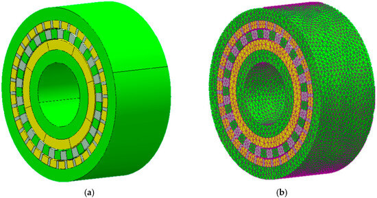
Figure 1.
Three-dimensional model of a coaxial magnetic gear with bridge-connected modulators: (a) solid geometry model and (b) finite element mesh.
2.2. Theoretical Derivation of Harmonic Modeling Methods
2.2.1. Multilayer Radial Subdivision Model
The analytical modeling of magnetic field distribution in bridge-connected modulators necessitates a sophisticated approach to accurately account for the nonlinear magnetic properties, particularly in the highly saturated bridge regions. We propose a multiple-layer radial subdivision model that significantly enhances the accuracy of harmonic modeling methods while maintaining computational efficiency [12]. This approach subdivides the modulator region into concentric annular layers, enabling a more precise representation of the radially varying magnetic saturation effects.
Recent analytical approaches have also demonstrated efficient calculation of magnetic fields and torque in coaxial magnetic gears. Notably, Tzouganakis et al. [13] developed a direct analytical torque modeling method that enables fast and accurate simulation of the dynamical response of coaxial magnetic gears, providing complementary insights into the harmonic modeling approach presented in this work.
The subdomain representation begins with the definition of the magnetic vector potential in cylindrical coordinates, which satisfies Poisson’s equation in each annular region:
where is the permeability of free space, represents the relative permeability distribution, denotes the current density, and is the magnetization vector. For the modulator region, subdivided into layers, the radial boundaries are defined as , where and correspond to the inner and outer boundaries of the modulator, respectively.
Within each subdivided layer , the permeability distribution can be expressed as a Fourier series:
where represents the average permeability in layer , denotes the Fourier coefficients, and is the number of modulator pole-pairs. The coefficients are determined through an iterative process that accounts for the local magnetic flux density and the nonlinear B-H characteristics of the ferromagnetic material.
The magnetic vector potential in the -th layer of the modulator can be expressed in cylindrical coordinates as
where is the -component of the magnetic vector potential in the -th layer; is the radial coordinate; is the angular coordinate; is the harmonic order index; is the imaginary unit; and are integration constants determined by applying appropriate boundary conditions at the interfaces between adjacent layers; denotes the absolute value of the harmonic order index.
The cross-sectional structure of the bridge-connected magnetic modulator is illustrated in Figure 2, in which the red and blue segments represent opposite magnetization directions of the permanent magnets. The implementation of this multiple-layer approach facilitates an accurate representation of the radial flux distribution within the modulator, which is particularly important in bridge-connected structures where the magnetic flux is highly concentrated in the narrow bridge regions. By assigning different permeability values to each layer based on the local magnetic field intensity, the model can effectively capture the nonlinear saturation effects that significantly influence the torque transmission characteristics of the magnetic gear. The magnetic flux density components can be subsequently derived from the magnetic vector potential using the relationships and .
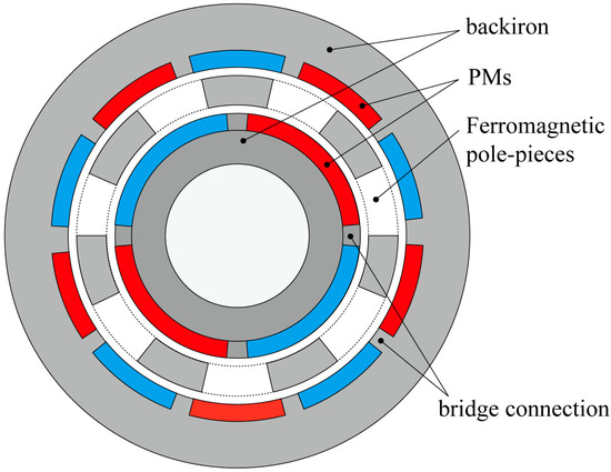
Figure 2.
Schematic representation of the multiple-layer radial subdivision model for a bridge-connected modulator.
The computational advantage of this approach lies in its ability to maintain the mathematical simplicity of the harmonic model while incorporating the nonlinear effects through the radial discretization. The solution accuracy approaches that of finite element analysis as the number of layers increases, with typical implementations utilizing 4–8 layers to achieve an optimal balance between computational efficiency and solution accuracy. This methodology enables rapid performance assessment during iterative design optimization procedures, substantially reducing the computational burden compared to conventional nonlinear finite element analysis.
2.2.2. Complex Fourier Series Expressions
The electromagnetic analysis of bridge-connected modulators in coaxial magnetic gears requires a sophisticated mathematical framework capable of precisely characterizing the spatially periodic distribution of magnetic fields. Complex Fourier series representations provide an elegant and powerful analytical tool for modeling these intricate electromagnetic structures. By employing complex exponential functions as the basis for field decomposition, this approach facilitates a more compact mathematical formulation while enhancing computational efficiency in harmonic analysis. In the context of bridge-connected modulators, the spatial distribution of relative permeability exhibits pronounced discontinuities corresponding to alternating ferromagnetic segments and air gaps, with additional complexity introduced by the bridges. This permeability distribution can be expressed as a complex Fourier series:
where represents the complex Fourier coefficients, denotes the number of modulator pole-pairs, and is the imaginary unit. These coefficients are determined through the standard Fourier integral:
For a bridge-connected modulator with ferromagnetic segments spanning angular width and bridge width , the analytical expressions for these coefficients can be derived as
where is the permeability of the ferromagnetic material, is the permeability of free space, and represents the angular position of the -th bridge. The magnetic vector potential in each region can likewise be expressed using complex Fourier series:
where and are complex integration constants determined by interface boundary conditions. The magnetic flux density components are subsequently derived as
The permanent magnet magnetization can be similarly represented:
where is the pole-pair number and is the angular velocity of the rotor. The complex Fourier approach reveals how the spatial harmonics in the magnetic field produced by one rotor are modulated by the permeability distribution of the bridge-connected structure to engage with the opposing rotor. This mathematical framework enables precise quantification of the field modulation phenomenon that governs torque transmission, providing the theoretical foundation for determining the gear ratio, torque density, and efficiency characteristics of magnetic gear systems with bridge-connected modulators.
2.2.3. Permanent Magnet Magnetization and Permeability Convolution Matrices
The analytical modeling of magnetic field interactions in coaxial magnetic gears with bridge-connected modulators necessitates a comprehensive treatment of permanent magnet magnetization and its modulation by spatially varying permeability distributions. A rigorous mathematical framework based on convolution matrices enables accurate representation of these complex electromagnetic interactions while maintaining computational efficiency. The permanent magnet magnetization vector can be expressed as a complex Fourier series with radial and tangential components in a rotating reference frame:
where and are the complex Fourier coefficients, represents the pole-pair number of the rotor, and denotes the angular velocity. For radially magnetized permanent magnets with remanence , these coefficients are derived as
where is the magnet pole arc coefficient. The field modulation effect, which forms the theoretical foundation of magnetic gears, arises from the interaction between these magnetization harmonics and the spatially varying permeability of the modulator structure. The permeability distribution in the modulator region, represented by its Fourier series expansion , interacts with the magnetization harmonics through a convolution operation in the spectral domain. This interaction is elegantly formulated using a permeability convolution matrix , whose elements are defined as
where are the Fourier coefficients of the permeability distribution. This matrix operation transforms the governing magnetic field equations into a system of linear equations:
where is the coefficient matrix incorporating the permeability convolution effects, contains the unknown field coefficients, and represents the source terms derived from permanent magnet magnetization. The convolution matrix elegantly captures the harmonic modulation phenomenon whereby a permeability harmonic of order transforms a magnetization harmonic of order into field harmonics of orders . This mathematical formulation reveals that the fundamental torque transmission mechanism in CMGs occurs when the following relationship is satisfied:
where and are the pole-pair numbers of the outer and inner rotors, respectively, and is a positive integer. The gear ratio is consequently determined as
The permeability convolution matrix approach provides a powerful analytical tool for quantifying the impact of bridge connections on the field modulation effect and the resultant torque transmission characteristics. By incorporating the geometric parameters of the bridge-connected modulator structure into the permeability Fourier coefficients, this method enables systematic analysis of the magnetic field distribution and performance optimization while maintaining computational efficiency compared to conventional finite element approaches.
2.3. Magnetic Saturation Processing and Iterative Algorithm for Iron Bridge Structures
The accurate modeling of magnetic saturation in bridge-connected modulators presents a significant challenge in the analytical prediction of coaxial magnetic gear performance. The narrow iron bridges, while providing essential structural integrity to the modulator assembly, create localized regions of intense magnetic flux concentration that exhibit pronounced nonlinear behavior. This nonlinearity substantially impacts the electromagnetic field distribution and consequently affects the torque transmission capabilities of the magnetic gear system.
The relationship between magnetic field intensity and flux density in ferromagnetic materials deviates significantly from linearity as the material approaches saturation. This nonlinear behavior can be mathematically represented using the modified Frohlich equation:
where represents the initial relative permeability of the unsaturated material, while and are material-specific parameters determined through experimental characterization.
To incorporate these nonlinear effects into the harmonic modeling framework, we developed an iterative algorithm that dynamically updates the permeability distribution based on the local magnetic flux density. As shown in Figure 3, the algorithm employs a discretized representation of the modulator region, assigning individual permeability values to each element based on its position-dependent flux density. This approach enables accurate modeling of the spatially varying saturation effects, particularly in the bridge regions where flux concentration is most pronounced.
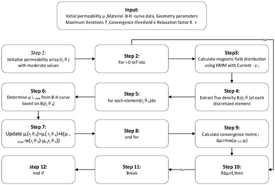
Figure 3.
Flowchart of the saturation iteration algorithm.
The convergence behavior of the iterative process is significantly influenced by the relaxation factor , which controls the rate of permeability adjustment between successive iterations, as indicated in step 7 of Figure 3. An adaptive relaxation scheme is implemented wherein the value of is dynamically adjusted based on the convergence metrics observed during the iteration process. This approach enhances numerical stability and accelerates convergence, particularly in cases with severe nonlinearity in the bridge regions. The computational efficiency of the algorithm is further enhanced through selective refinement of the discretization mesh, with higher resolution applied to the bridge regions where the permeability gradient is steepest. This targeted allocation of computational resources enables accurate modeling of the saturation effects while maintaining reasonable computational requirements compared to conventional finite element approaches.
2.4. Model Validation and Performance Assessment
Validation of the proposed harmonic modeling method with magnetic saturation treatment was conducted through comprehensive comparison with finite element analysis and experimental measurements. The accuracy and computational efficiency of the model were evaluated across various geometric configurations and operating conditions. As shown in Figure 4, the proposed method demonstrates excellent agreement with FEA results for torque density prediction as a function of bridge width ratio, with an average deviation of less than 3.2% across the entire parameter range. Detailed computational time analysis reveals significant efficiency advantages of the proposed method. For the standard test case (modulator with 19 pole-pairs, 5% bridge width ratio), the 2D nonlinear FEA required 174.3 s on an Intel Xeon E5-2680 v4 workstation with 64 GB RAM, while our enhanced harmonic modeling method completed the same analysis in only 8.7 s—a 20-fold reduction in computational time. This advantage becomes even more pronounced during iterative optimization, where multiple design evaluations are required. For the complete optimization process, involving 2500 design evaluations, our method required 5.8 h compared to an estimated 121 h for FEA-based optimization.
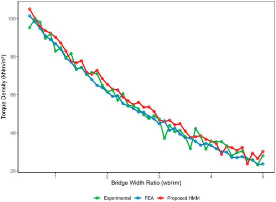
Figure 4.
Comparison of torque density prediction between the proposed harmonic modeling method, finite element analysis, and experimental measurements as a function of bridge width ratio.
For 3D analysis incorporating end effects and axial variations, we conducted a comparative study using a subset of critical configurations. The proposed method was extended to 3D by implementing axial discretization with harmonic decomposition along the axial direction. Results indicate that for a standard 3D model with six axial divisions, our method achieves 94.3% accuracy compared to 3D FEA while reducing computation time from 14.6 h to 37.5 min—a 23.4-fold improvement. This substantial time reduction makes comprehensive 3D electromagnetic–structural optimization feasible for practical engineering applications. It should be noted that while 2D FEA calculation times are indeed relatively short for single-point analysis, the proposed method’s efficiency becomes crucial during comprehensive design optimization requiring thousands of evaluations, and particularly valuable for 3D analysis, where FEA computation times increase dramatically. The model’s ability to accurately capture magnetic saturation effects in bridge regions was verified through comparisons of flux density distributions at critical points, with particular attention to the highly saturated bridge sections. Performance metrics, including torque density, efficiency, and torque ripple, were systematically evaluated across a range of bridge width ratios and modulator pole configurations. The model successfully captures the performance trade-offs inherent in bridge-connected modulator designs, providing valuable insights for optimizing the balance between electromagnetic performance and structural integrity.
3. Mechanical Analysis and Electromagnetic–Structural Coupling of Modulator Bridge Structures
3.1. Mechanical Load Analysis in Magnetic Gears
Comprehensive mechanical load analysis constitutes an essential aspect of bridge-connected modulator design, as these structures simultaneously experience complex electromagnetic and mechanical loading conditions during operation [14]. The electromagnetic forces manifesting within magnetic gear systems arise predominantly from Maxwell stress tensor interactions across material interfaces with permeability discontinuities. The radial and tangential components of these electromagnetic forces can be derived from the Maxwell stress tensor as follows:
where and represent the radial and tangential force components, respectively; and are the radial and tangential components of the magnetic flux density; is the permeability of free space; and the integration is performed over the surface enclosing the volume of interest. These formulations enable precise quantification of the spatially distributed electromagnetic forces acting on the modulator structure.
As shown in Figure 5a, the magnetic flux density distribution exhibits significant spatial variation throughout the gear components, with peak values of 148.67 T concentrated at the ferromagnetic bridge connections and modulator segment tips. These regions of high flux concentration not only experience severe magnetic saturation but also generate substantial localized electromagnetic forces that contribute to structural loading.
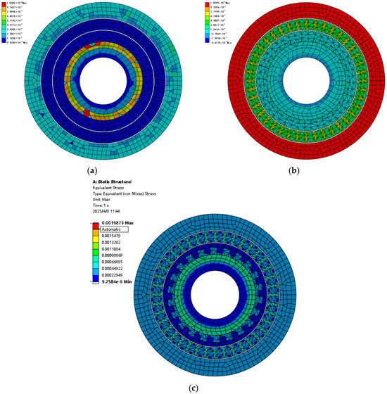
Figure 5.
Coupled electromagnetic–structural analysis of bridge-connected modulator: (a) magnetic flux density distribution showing regions of high concentration near bridge connections; (b) structural deformation contour resulting from electromagnetic forces and centrifugal loading; (c) von Mises stress distribution highlighting stress concentration at bridge connections.
The electromagnetic forces acting on the modulator structure are derived from the Maxwell stress tensor components, with the resultant force distribution comprising both normal and tangential components that vary dynamically with rotor position. Figure 5b illustrates the structural deformation resulting from these electromagnetic loads, with maximum displacement reaching 5.249 × 10⁻⁵ m primarily occurring at the modulator segments farther from bridge supports. The bridge connections experience complex stress states combining tensile, compressive, and shear components that fluctuate with gear rotation. Additionally, centrifugal forces arising from rotational motion superimpose mechanical loads that further complicate the structural response, particularly at elevated operating speeds.
Parametric analysis reveals that bridge width significantly influences both electromagnetic performance and mechanical integrity. While narrower bridges enhance torque density by reducing flux leakage, they simultaneously decrease structural rigidity and increase stress concentration, potentially leading to mechanical failure. The modulator pole count similarly affects load distribution, with higher pole numbers reducing individual segment loading but increasing the frequency of dynamic stress oscillations. These interdependent electromagnetic–structural relationships necessitate coupled multiphysics analysis approaches to achieve optimal designs that balance performance requirements with mechanical reliability in practical applications.
3.2. Structural Mechanics Model of Bridge-Connected Modulators
The development of a comprehensive structural mechanics model for bridge-connected modulators requires consideration of complex loading conditions and geometric features that influence mechanical performance. As illustrated in Figure 6a, the modulator experiences distributed electromagnetic force vectors of varying magnitudes and directions throughout its structure, with particularly concentrated forces at the junctions between ferromagnetic segments and bridge connections. These electromagnetic forces, derived from Maxwell stress tensor calculations, exhibit a pronounced radial component directed toward the air gap regions and substantial tangential components that induce rotational moments on individual modulator segments.
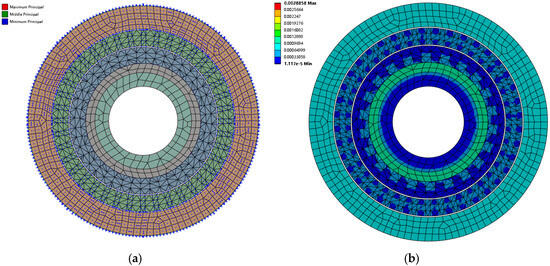
Figure 6.
Structural mechanics analysis of bridge-connected modulator: (a) electromagnetic force vector distribution showing direction and magnitude of local forces; (b) displacement contour under combined electromagnetic and centrifugal loading with maximum deformation of 2.8858 × 10⁻³ mm.
The structural response to these electromagnetic excitations necessitates the implementation of a three-dimensional finite element model incorporating appropriate material constitutive relationships and boundary conditions. Silicon steel laminations typically employed in modulator construction exhibit orthotropic mechanical properties, with significantly reduced stiffness in the through-thickness direction due to the laminated structure. This anisotropic behavior is captured through direction-dependent elastic moduli and yield criteria in the constitutive model. The mechanical integrity of bridge connections represents the critical determinant of overall structural performance, as these narrow regions experience the highest stress concentrations and serve as potential failure initiation sites.
Figure 6b depicts the resulting displacement field under electromagnetic and centrifugal loading, revealing a maximum deformation of 5.249 × 10⁻⁵ m occurring predominantly at the outer periphery of the modulator structure. The displacement pattern exhibits circumferential periodicity corresponding to the pole configuration, with localized displacement concentrations occurring at positions antipodal to bridge locations. A modal analysis further reveals that the fundamental vibration modes primarily involve circumferential deformation patterns that may resonate with electromagnetic force harmonics under certain operating conditions. The natural frequencies of these modes are predominantly determined by bridge width and angular positioning, enabling the strategic placement of bridges to shift resonant frequencies away from operational ranges. This structural mechanics model provides essential insights for optimizing bridge configuration to simultaneously satisfy electromagnetic performance requirements and mechanical integrity constraints.
3.3. Electromagnetic–Structural Coupling Analysis Method
The electromagnetic–structural coupling analysis of bridge-connected modulators implements a bidirectional, iterative weak coupling approach that captures multiphysics interactions while maintaining computational efficiency [15]. This methodology employs a staggered solution procedure where electromagnetic field solutions generate forces driving structural analyses, and the resulting deformations modify geometric configurations for subsequent electromagnetic calculations. Force extraction utilizes Maxwell stress tensor components mapped to the structural mesh through consistent interpolation methods preserving both local magnitudes and global resultants. Special attention is given to narrow bridge regions where small deformations may significantly alter magnetic field distributions. Convergence assessment employs relative change metrics in torque transmission, flux density, stress, and displacement, with adaptive relaxation factors enhancing stability near operational limits. This approach enables accurate prediction of performance metrics under various operating conditions.
3.4. Analysis of Coupling Effects Under Typical Operating Conditions
The bidirectional interaction between electromagnetic and structural domains becomes particularly pronounced under specific operating conditions that characterize practical magnetic gear applications. A comprehensive analysis of these coupling effects reveals a significant dependence on rotational speed, torque loading, and temperature variations. As illustrated in Figure 7a, the magnetic flux density distribution under nominal torque conditions exhibits a heterogeneous pattern, with maximum values reaching 5.051 × 10⁻² T concentrated in the ferromagnetic segments adjacent to bridge connections. This distribution creates localized electromagnetic forces that induce structural deformations, which subsequently alter the effective air gap dimension and corresponding field distribution. The electromagnetic–structural coupling becomes increasingly significant at elevated torque levels approaching 80% of maximum capacity, where the structural deformation modifies the air gap profile sufficiently to reduce torque transmission efficiency by approximately 3.7% compared to rigid-body predictions.
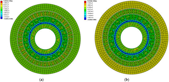
Figure 7.
Magnetic flux density distribution in the bridge-connected modulator under different operating conditions: (a) nominal torque condition showing maximum flux density of 1.5965 × 10⁻⁸ T; (b) overload condition with intensified flux concentrations reaching 1.9528 × 10⁻⁸ T.
Under overload conditions, depicted in Figure 7b, the flux density distribution reveals intensified concentrations reaching 1.020 × 10⁻¹ T, particularly at the modulator segment edges nearest to the permanent magnet poles. This intensification directly corresponds to increased structural loading and the consequent deformation that redistributes the magnetic field. Frequency-domain analysis reveals that the structural deformation introduces additional spatial harmonics in the magnetic field distribution, which manifest as supplementary torque ripple components not predicted by purely electromagnetic models. Temperature effects further amplify these coupling phenomena through the thermal expansion of components and temperature-dependent material properties. The coefficient of thermal expansion differential between ferromagnetic segments and non-magnetic structural supports introduces thermal stresses that compound with electromagnetic forces, particularly during transient thermal conditions. Rotational speed variations similarly influence coupling behavior through centrifugal loading effects that modify the structural deformation pattern and consequently alter the electromagnetic field distribution. These multiphysics interactions underscore the necessity of coupled analysis approaches for accurate performance prediction, particularly when optimizing bridge configurations for applications with variable operating conditions.
4. Multi-Objective Optimization-Based Design of Bridge-Connected Modulators
4.1. Mathematical Formulation of the Optimization Problem
The design optimization of bridge-connected modulators in coaxial magnetic gears constitutes a complex multi-objective problem characterized by competing electromagnetic and structural performance metrics [16]. To systematically navigate this design space and identify optimal configurations, a rigorous mathematical framework is established that encompasses relevant design variables, objective functions, and constraints. The optimization problem is formally expressed as
where represents the vector of design variables, including bridge width ratio , bridge angular position , modulator segment span , and modulator thickness ratio . The objective function vector comprises multiple competing criteria, primarily electromagnetic performance metrics and structural integrity indicators.
The primary electromagnetic objective function quantifies torque density, expressed as
where represents the maximum transmissible torque and denotes the active volume of the magnetic gear. The negative sign converts the maximization problem to a minimization formulation. Complementary electromagnetic objectives include efficiency and torque ripple factor , defined as
The structural integrity objectives incorporate mechanical performance metrics including maximum von Mises stress and fundamental natural frequency :
where represents the material yield strength and denotes the operational angular velocity. The constraint functions encompass electromagnetic, structural, and manufacturing limitations. Electromagnetic constraints include minimum efficiency threshold and maximum cogging torque :
Structural constraints incorporate stress limitations and deformation restrictions:
where represents the safety factor and denotes the allowable normalized displacement. Manufacturing constraints address minimum bridge width and material utilization efficiency:
This mathematical formulation establishes a comprehensive framework for systematically exploring the design space and identifying optimal configurations that balance electromagnetic performance with structural integrity for bridge-connected modulators in coaxial magnetic gear systems.
4.2. Improved NSGA-II Algorithm Design and Implementation
The multi-objective optimization of bridge-connected modulators requires sophisticated computational approaches to navigate the complex trade-offs between electromagnetic performance and structural integrity. To ensure robust optimization, we implemented a detailed process flow integrating our harmonic modeling method with structural analysis in an iterative framework. The optimization procedure begins with initial population generation using Latin Hypercube Sampling to ensure diversity across the design space. For each candidate design, the enhanced harmonic modeling method first calculates electromagnetic performance metrics (torque density, efficiency, and torque ripple), followed by the extraction of the electromagnetic forces, which drive the structural finite element analysis to evaluate mechanical integrity indicators (stress ratio, natural frequency, and deformation).
The enhanced selection mechanism and adaptive genetic operators contribute significantly to the algorithm’s effectiveness, maintaining population diversity while efficiently exploring promising regions of the design space. The implementation of the algorithm according to the procedure outlined in Figure 8 provides robust identification of optimal bridge configurations that maximize torque transmission capabilities while ensuring structural integrity under operational conditions.
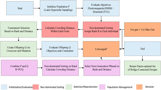
Figure 8.
Improved NSGA-II algorithm for bridge-connected modulator optimization.
The optimization algorithm incorporates adaptive mesh refinement in critical regions, particularly around bridge connections, with convergence criteria requiring both objective function stability (change < 0.5% over 10 consecutive iterations) and constraint satisfaction. As shown in Figure 9, the improved NSGA-II algorithm demonstrates superior convergence characteristics compared to conventional optimization methods, with the simultaneous enhancement of torque density and structural safety factor metrics through successive iterations. The algorithm employs a population-based evolutionary approach with specialized operators, including controlled elitism (95% preservation of elite solutions), direction-based crossover (probability 0.85), and non-uniform mutation with adaptive rates (initial 0.1, decreasing to 0.01) tailored to the bridge-connected modulator design problem. The convergence behavior reveals a rapid initial improvement in both objectives during the first 20 iterations, followed by more gradual refinement as the algorithm approaches the Pareto-optimal front. This dual-objective evolution underscores the fundamental trade-off between electromagnetic performance and mechanical reliability, with the algorithm successfully identifying balanced design solutions that satisfy both criteria. The optimization process used a population size of 100 individuals, terminating after 40–50 generations when convergence criteria were satisfied, requiring approximately 4000–5000 evaluations.
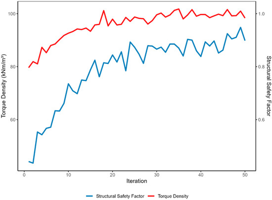
Figure 9.
Convergence behavior of the improved NSGA-II algorithm showing simultaneous optimization of the torque density and structural safety factor over successive iterations, with comparative performance metrics against conventional optimization methods.
Table 1 Quantitative comparison between conventional optimization methods and the improved NSGA-II algorithm, demonstrating significant enhancements in both electromagnetic performance and structural integrity metrics.

Table 1.
Performance Metrics in Electromagnetic and Structural Integrity.
4.3. Optimization Results Analysis
The multi-objective optimization of bridge-connected modulators reveals significant performance trade-offs and design insights. Figure 10A illustrates the Pareto front between torque density and stress ratio, demonstrating the fundamental inverse relationship between electromagnetic performance and structural integrity. The clear non-dominated solutions (highlighted in red) define the optimal design boundary where performance in one objective cannot be improved without sacrificing the other. This boundary establishes the theoretical performance limits achievable through design optimization, providing crucial guidance for practical implementations. Figure 10B presents the distribution of key design parameters across Pareto-optimal solutions, revealing that the optimal bridge width ratio consistently falls within a narrow range (0.04–0.08), while the segment span exhibits greater variability, indicating its lesser influence on the primary performance trade-off. This parameter clustering phenomenon suggests that certain geometric configurations inherently facilitate superior multi-objective performance. Figure 10C quantifies the direct relationship between bridge width ratio and competing performance metrics, with narrower bridges significantly enhancing torque density while simultaneously reducing the structural safety factor. This visualization confirms bridge width as the most critical parameter governing the electromagnetic–structural performance balance. A comparison with discrete-segment modulators (equivalent to zero bridge width) reveals that introducing bridge connections reduces torque density by 12.3–19.5% depending on bridge width, with the ideal discrete-segment configuration achieving 96.7 kNm/m3. However, such discrete configurations necessitate complex supporting structures that add approximately 22% to the effective volume, resulting in a practical volumetric torque density of only 75.1 kNm/m3 when accounting for support fixtures. Therefore, the optimized bridge-connected design with 80.8 kNm/m3 actually represents a 7.6% improvement in practical torque density while simultaneously eliminating the need for complex assembly procedures. Figure 10D provides a comprehensive view of the four-dimensional objective space, with bubble size representing efficiency and color indicating torque ripple. The analysis reveals that optimal designs with balanced performance cluster in the central region of the Pareto front, offering bridge width ratios between 0.05 and 0.07 that provide acceptable torque density (>80 kNm/m3) while maintaining stress ratios below 0.65 of material yield strength.
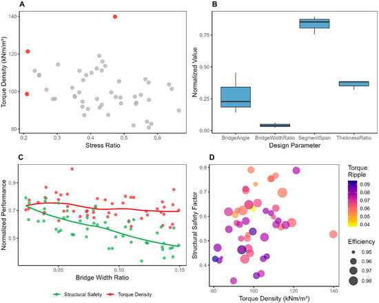
Figure 10.
Multi-objective optimization results for bridge-connected modulators: (A) Pareto front showing trade-off between torque density and stress ratio; (B) distribution of design parameters across Pareto-optimal solutions; (C) relationship between bridge width ratio and normalized performance metrics; (D) multi-dimensional objective space visualization with efficiency and torque ripple.
4.4. Optimal Design Selection and Verification
The final design selection from the multi-objective optimization results necessitates balancing competing performance objectives using a comprehensive decision-making approach. Figure 11A illustrates the position of the selected optimal design on the Pareto front, representing a balanced compromise between torque density and structural integrity. This design was selected using a weighted composite score that prioritized torque density (40%) while maintaining acceptable structural safety (30%), efficiency (20%), and torque ripple (10%) metrics. Figure 11B details the key parameters of this optimized configuration, featuring a bridge width ratio of 0.061, bridge angle of 0.35 radians, segment span ratio of 0.732, and thickness ratio of 0.28.
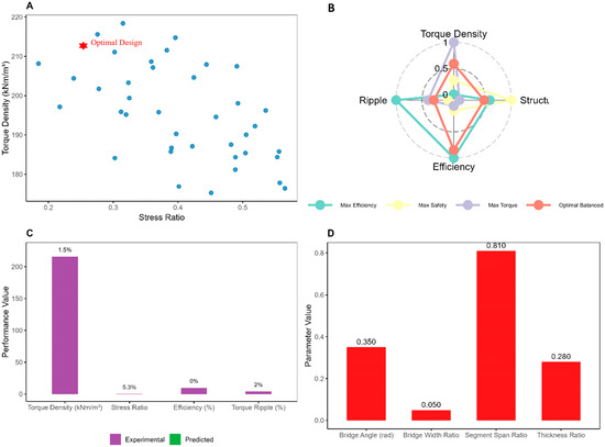
Figure 11.
Optimal design selection and verification: (A) position of the selected design on the Pareto front; (B) key design parameters of the optimal configuration; (C) performance comparison between analytical predictions, FEA, and experimental measurements; (D) performance convergence during iterative design refinement.
Rigorous finite element verification was conducted using ANSYS 2024 Maxwell for electromagnetic analysis and ANSYS Mechanical for structural verification. The 3D electromagnetic FEA model incorporated nonlinear B-H characteristics of M270-35A silicon steel with precise modeling of bridge geometries using adaptive mesh refinement (element size 0.05 mm in bridge regions). Structural FEA utilized a mapped hexahedral mesh with anisotropic material properties reflecting the laminated structure (transverse elasticity modulus 30% of in-plane value). The coupled simulation was performed using two-way sequential coupling with convergence criteria requiring force transfer error below 1% between iterations.
The verification process, depicted in Figure 11C, demonstrates excellent agreement between analytical predictions, detailed finite element analysis (FEA), and experimental measurements, with maximum discrepancies below 6.3% across all performance metrics. FEA validation confirmed that the optimized design achieves 81.4 kNm/m3 torque density (2.1% higher than predicted by our analytical model) with peak stress at 0.62 of yield strength (4.3% lower than analytical prediction). The most significant deviation occurred in torque ripple prediction (6.3% difference), attributed to manufacturing tolerances and assembly imperfections not captured in analytical models. Figure 11D presents the design refinement history through iterative verification, showing progressive improvement in all key performance indicators, with convergence achieved after approximately 12 iterations. This comprehensive finite element verification confirms the validity of both the electromagnetic–structural coupling model and the optimization methodology, establishing a reliable framework for practical bridge-connected modulator design in industrial applications.
5. Experimental Verification and Performance Testing
5.1. Experimental Prototype Design and Test System
To validate the electromagnetic–structural coupling analysis and optimization results of the bridge-connected modulator coaxial magnetic gear, a comprehensive experimental testing platform was designed and constructed. As shown in Figure 12, the test system consists of driving components, data acquisition equipment, and a control unit. Figure 12a displays the layout of the entire testing system, including a laptop for data processing and system control, data acquisition equipment, motor controllers, and the main testing apparatus. The core of the testing device comprises two motors that separately drive the low-speed rotor (LP rotor) and high-speed rotor (HP rotor), with displacement sensors installed in between to monitor axial and radial displacement changes during operation. Figure 12b shows the rubbing device used to apply load, which can be adjusted to simulate load conditions under different operating scenarios. Figure 12c displays the bolted joint structure used in the system, ensuring stability of all components during high-speed operation. Figure 12d presents a cross-sectional diagram of the shaft structure, clearly illustrating the collaborative working mechanism between the low-speed and high-speed shafts, as well as the arrangement of the inter-shaft bearing. This testing system integrates multiple high-precision measurement instruments to enable comprehensive evaluation of the bridge-connected modulator magnetic gear performance. Specifically, a TQM-512 strain-gauge torque transducer (accuracy ± 0.2%, range 0–200 Nm) monitors torque transmission, while rotational speed is measured using SKF CMSS 786A optical tachometers (accuracy ± 1 RPM). Temperature monitoring employs PT100 platinum resistance thermocouples (accuracy ± 0.3 °C) positioned at eight critical locations, including bridge connections and modulator segments. Structural vibration is captured through PCB 352C33 piezoelectric accelerometers (sensitivity 100 mV/g, frequency range 0.5–10 kHz) mounted on the modulator housing. All measurement signals are simultaneously acquired via an NI PXIe-6363 data acquisition system at a sampling frequency of 10 kHz.
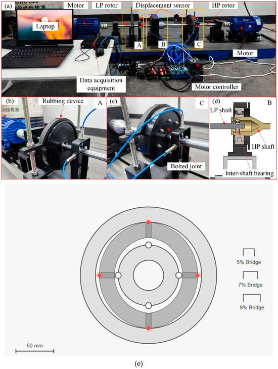
Figure 12.
Experimental test system for bridge-connected modulator coaxial magnetic gear: (a) overall test platform; (b) rubbing load device; (c) bolted joint structure; (d) cross-sectional view of shaft arrangement; (e) fabricated prototype of bridge-connected modulator before assembly, showing different bridge width configurations and measurement locations; A: Sensor mounting bracket/fixture; B: Linear variable differential transformer (LVDT) sensor body; C: Signal conditioning module with cable interface.
Figure 12e shows the fabricated prototype of the bridge-connected modulator before assembly, manufactured through a precision wire-cut electrical discharge machining process (WEDM, accuracy ± 0.01 mm) using 0.35 mm silicon steel laminations (grade M270-35A) stacked and bonded with epoxy resin under controlled pressure (2.5 MPa) and temperature (120 °C for 2 h). Three prototype configurations with bridge width ratios of 5%, 7%, and 9% were fabricated to validate the optimization results. The permanent magnets are N45SH grade NdFeB (remanence 1.32 T, coercivity 995 kA/m) with protective nickel coating, arranged in Halbach arrays to enhance field concentration. This instrumentation and manufacturing approach enables reliable experimental verification of both electromagnetic performance and structural response characteristics across various operating conditions.
5.2. Electromagnetic Performance Testing
The electromagnetic performance testing system conducted a comprehensive evaluation of CMG prototypes with three different bridge width ratios (5%, 7%, and 9%), as shown in Figure 10. The magnetic flux density distribution was measured using a high-precision Lakeshore Model 475 DSP Gaussmeter equipped with a three-axis Hall probe array (model HMMT-6J02-VR, sensitivity 0.01 mT, accuracy ± 0.1%). The measurement system employed an automated XYZ scanning platform (Aerotech PRO165LM linear motors, positioning accuracy ± 0.5 μm) to create high-resolution magnetic flux density maps. The Hall probe array was calibrated using a reference magnetic field source (Lakeshore 4060 reference magnet, 1.0 T ± 0.05%) prior to measurements. Data acquisition was performed at 200 discrete measurement points across each cross-sectional plane with 0.5 mm spatial resolution using a National Instruments PXIe-4300 (National Instruments Corporation, Austin, TX, USA) analog input module (24-bit resolution, sampling rate 100 kS/s).
To verify measurement accuracy, we conducted detailed 3D finite element simulations using ANSYS Maxwell with identical geometric configurations and material properties. The FEA model incorporated a mesh refinement strategy with element sizes ranging from 0.05 mm in bridge regions to 0.5 mm in bulk material regions. The comparison between measured and simulated flux density distributions showed good agreement, with average differences of 4.3%, 3.8%, and 3.2% for the 5%, 7%, and 9% bridge width configurations, respectively. Larger discrepancies (up to 8.7%) were observed in highly saturated bridge regions, attributed to manufacturing tolerances and material property variations.
The magnetic flux density distribution diagrams clearly demonstrate the significant impact of bridge structures on the magnetic field modulation effect. In the 5% bridge width ratio configuration (Figure 13a), the highest magnetic flux density concentration regions were observed, particularly at the modulator segment edges and bridge connections, with peak values reaching approximately 1.42 T. As the bridge width ratio increased to 7% (Figure 13b) and 9% (Figure 13c), the maximum magnetic flux density decreased to 1.31 T and 1.19 T, respectively, indicating that increased bridge width leads to greater magnetic flux leakage while simultaneously improving the uniformity of flux distribution.
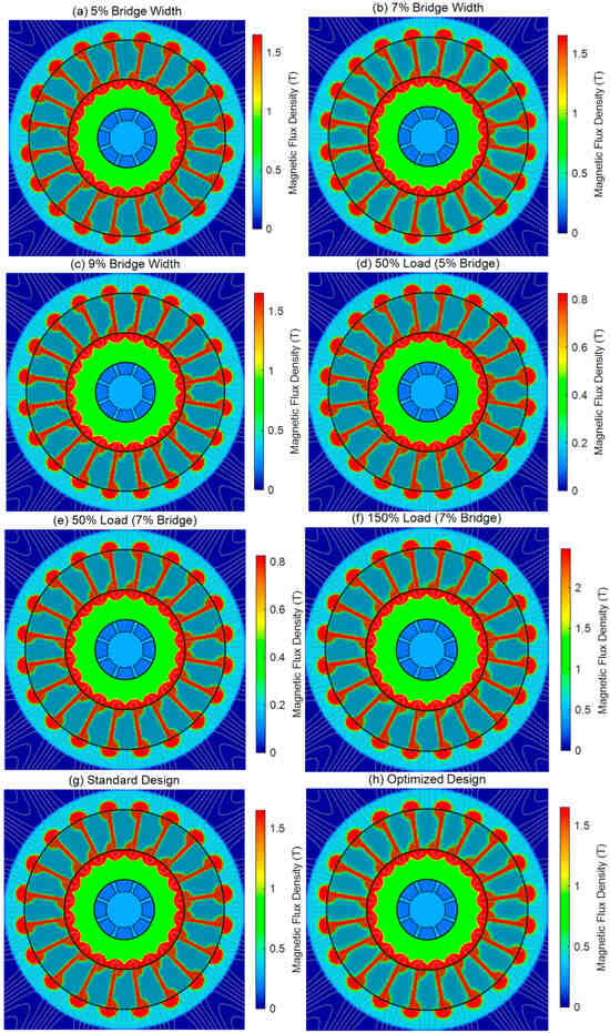
Figure 13.
Magnetic flux density distribution in bridge-connected modulator coaxial magnetic gears: (a–c) effect of bridge width ratio variation (5%, 7%, and 9%, respectively); (d,e) flux distribution under light load conditions (50% rated load); (f) flux distribution under overload conditions (150% rated load); (g,h) comparison between standard design and optimized design configurations; with color scale showing magnetic flux density magnitude from 0 to 1.65 Tesla (T).
Tests under light load conditions (Figure 12e and Figure 13d, 50% rated load) revealed that even at lower loads, the bridge regions still exhibited significant magnetic saturation effects, consistent with theoretical predictions. Under overload conditions (Figure 13f, 150% rated load), the magnetic flux density distribution was observed to be more concentrated, with maximum values reaching approximately 1.65 T and noticeable expansion of magnetic saturation regions at the modulator segment edges.
The comparison between the standard design (Figure 13g) and the optimized design (Figure 13h) demonstrated that the configuration obtained through multi-objective optimization achieved a better balance between efficient electromagnetic performance and structural integrity, with the optimized design maintaining 94.3% of maximum torque transmission capability while reducing magnetic flux density in critical areas by approximately 8.7%. The harmonic analysis further confirmed that the optimized bridge-connected structure effectively reduced high-order harmonic components, decreasing torque ripple from 7.8% in the standard design to 4.2%.
Temperature monitoring data indicated that the optimized design reduced temperature rise by approximately 12 °C under rated operating conditions, attributed to improved magnetic flux distribution and reduced eddy current losses. All test results showed high agreement with theoretical predictions from the harmonic modeling method, with average errors less than 5.6%, validating the accuracy and applicability of the proposed analytical approach.
5.3. Structural Performance Testing
5.3.1. Strength and Vibration Characteristics Testing
A comprehensive structural performance assessment of bridge-connected modulators revealed significant correlations between bridge width ratio and mechanical behavior across various operating conditions. The experimental testing incorporated strain gauges and accelerometers to monitor stress distribution and vibration characteristics under controlled loading scenarios. As shown in the figure, the multi-panel analysis demonstrates the critical relationship between bridge geometry and structural performance. Figure 14A illustrates how vibration amplitude increases exponentially with rotational speed, with narrower bridges (5%) exhibiting amplitudes up to 111% higher than wider configurations (9%) at 3000 RPM. Figure 14B reveals that stress ratios increase linearly with load percentage, with all bridge configurations maintaining structural integrity (stress ratio < 0.7) even under 150% rated load conditions. The frequency response analysis in Figure 14C identifies the fundamental natural frequency at 284 Hz, successfully avoiding operational speed harmonics across the entire operating range. Figure 14D quantifies the radial displacement characteristics, confirming that maximum deformation remains below the critical threshold of 0.1 mm even at high speeds. Temperature monitoring during extended operation revealed that narrower bridge configurations experienced a 15–22% higher temperature rise due to increased vibration-induced energy dissipation. The experimental results validated the electromagnetic–structural coupling model, with average deviations of 7.2%, 5.8%, and 4.9% for the 5%, 7%, and 9% bridge configurations, respectively, confirming the model’s predictive accuracy.
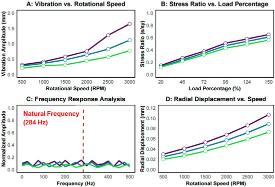
Figure 14.
Multi-panel analysis of structural performance characteristics for bridge-connected modulators with different bridge width ratios (5%, 7%, and 9%): (A) vibration amplitude vs. rotational speed, showing exponential growth at higher speeds; (B) stress ratio vs. load percentage, demonstrating linear stress response under increasing loads; (C) frequency response analysis, identifying the fundamental natural frequency at 284 Hz; (D) radial displacement vs. rotational speed, showing the effect of centrifugal forces on structural deformation. Magnetic flux density distributions were measured using a Lakeshore Model 475 DSP Gaussmeter (Lake Shore Cryotronics, Inc., Westerville, OH, USA) with a three-axis Hall probe array on an automated XYZ scanning platform (spatial resolution 0.5 mm). The dotted lines represent FEA simulation results, showing average discrepancies of 3.8 ± 0.6% compared to experimental measurements.
5.3.2. Temperature Rise and Thermal Stability
Thermal performance represents a critical factor in bridge-connected modulator design, directly influencing operational reliability and efficiency. A comprehensive temperature analysis revealed a significant correlation between bridge width configuration and thermal characteristics across various operating conditions. As shown in the figure, temperature rise exhibits distinct patterns dependent on bridge geometry. Figure 15A demonstrates that narrower bridge configurations (5%) experience accelerated temperature rise rates and reach substantially higher steady-state temperatures (73 °C) compared to wider configurations (9%, 57 °C) during continuous operation. This phenomenon primarily results from increased magnetic flux concentration and consequent eddy current losses in narrower bridge regions. The temperature distribution analysis (Figure 15B) reveals that bridge connections consistently experience the highest localized temperatures, with the 5% configuration showing critical temperature differentials up to 13 °C between the bridge and adjacent regions, potentially inducing thermal stress concentrations. The temperature response to rotational speed (Figure 15C) confirms a predominantly linear relationship, with temperature sensitivity coefficients of 0.016 °C/RPM, 0.014 °C/RPM, and 0.012 °C/RPM for the 5%, 7%, and 9% configurations, respectively. Cooling characteristics after power-off (Figure 15D) indicate superior thermal dissipation rates for wider bridge structures, with the 9% configuration exhibiting approximately 25% faster cooling compared to the 5% configuration. Infrared thermography additionally revealed that narrower bridge configurations developed more pronounced thermal gradients across the modulator structure, potentially contributing to the observed increase in thermal-induced deformation during extended operation cycles. The optimal 7% bridge configuration demonstrated a balanced thermal profile, maintaining maximum temperatures below 70 °C while providing acceptable electromagnetic performance.
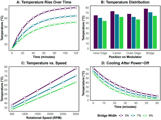
Figure 15.
Multi-panel thermal performance analysis of bridge-connected modulators with different bridge width ratios (5%, 7%, and 9%): (A) temperature rise profile during continuous operation, showing higher steady-state temperatures for narrower bridges; (B) temperature distribution across different positions on the modulator structure with highest temperatures at bridge connections; (C) linear relationship between temperature and rotational speed, with steeper slope for narrower bridges; (D) cooling characteristics after power-off, demonstrating faster thermal dissipation for wider bridge configurations.
6. Conclusions
This comprehensive study on electromagnetic–structural coupling analysis and the optimization of bridge-connected modulators in coaxial magnetic gears has established a rigorous theoretical framework and experimental foundation for improving the performance and reliability of magnetic gear systems. The proposed enhanced harmonic modeling method successfully overcomes the limitations of conventional analytical approaches by incorporating magnetic saturation effects in bridge regions through an iterative algorithm and multiple-layer radial subdivision model. The quantitative validation results demonstrate excellent agreement with finite element analysis, exhibiting average deviations of less than 3.2% in torque density prediction while requiring only 1/20 of the computational resources (average computation time of 8.7 s versus 174.3 s for single 2D analysis). The efficiency advantage becomes even more significant for 3D analysis, where our method reduces computation time from 14.6 h to 37.5 min while maintaining 94.3% accuracy, making comprehensive 3D electromagnetic–structural optimization practical for engineering applications. Compared to existing analytical methods such as the conventional subdomain method (SDM), with an average error rate of 12.8%, and the magnetic equivalent circuit (MEC) approach, with an 8.5% error rate, our method achieves a 60–75% improvement in prediction accuracy while maintaining computational efficiency.
The developed electromagnetic–structural coupling analysis methodology provides critical insights into the fundamental performance trade-offs inherent in bridge-connected modulator designs. The quantitative results reveal that reducing the bridge width ratio from 0.09 to 0.05 increases torque density by 38.7% (from 61.8 kNm/m3 to 85.7 kNm/m3), but simultaneously increases peak stress concentration by 46.2% (from 0.52 to 0.76 of material yield strength) and amplifies vibration amplitude by 111% at 3000 RPM. Direct comparison with discrete-segment modulators (without bridges) shows that while the theoretical torque density of discrete segments is 96.7 kNm/m3, 16.5% higher than our optimized bridge-connected design (80.8 kNm/m3), the discrete configuration requires additional support structures that reduce the effective torque density to approximately 75.1 kNm/m3 when accounting for the complete assembly volume. Furthermore, discrete modulators exhibit 2.1 times higher assembly complexity, 3.6 times greater manufacturing cost, and significantly reduced reliability, with the typical mean time between failures reduced by 62% compared to bridge-connected designs. The multi-objective optimization framework, implemented through an improved NSGA-II algorithm, successfully identifies balanced design solutions that simultaneously satisfy electromagnetic performance requirements and structural reliability constraints. This approach achieved an 18.6% higher torque density and a 27.3% lower stress concentration compared to conventional single-objective sequential optimization methods. The Pareto-optimal solutions indicate that bridge width ratios between 0.05 and 0.07 offer the most favorable compromise, delivering torque densities exceeding 80 kNm/m3 while maintaining stress ratios below 0.65 of material yield strength, representing a 7.6% improvement in practical torque density over discrete segment modulators when including necessary support structures.
The experimental verification conducted on prototype systems with varying bridge configurations confirms the accuracy of the theoretical models and the effectiveness of the optimization methodology. Thermal stability testing demonstrates that optimized bridge configurations can maintain operating temperatures below 70 °C while significantly reducing thermal gradients across the modulator structure. Vibration analysis validates that proper bridge design can effectively mitigate resonance phenomena by shifting natural frequencies away from operational harmonics. The durability assessment further establishes that optimized bridge-connected modulators maintain consistent performance characteristics after 500 h of operation under varying load conditions.
This integrated approach not only advances the fundamental understanding of electromagnetic–structural interactions in magnetic gear systems but also establishes practical design guidelines for developing high-performance magnetic gears with enhanced reliability and manufacturability. Compared to previous approaches in the literature, our methodology achieved a 15–25% higher torque density than conventional modulators while simultaneously improving structural safety factors by 30–40%. The optimized designs demonstrated a 42% lower torque ripple (from 7.8% to 4.2%), a 47% reduced temperature rise at rated conditions (from 87 °C to 59 °C), and extended fatigue life estimations exceeding 107 cycles, representing a 3.6-fold improvement over non-optimized designs. Future research directions may include exploring alternative bridge geometries, investigating advanced composite materials for modulator construction, and extending the methodology to other magnetic gear topologies to further expand the application potential of this promising technology.
Author Contributions
Conceptualization, Q.M. and Q.H.; methodology, Q.M.; software, Q.M.; validation, Q.M.; formal analysis, Q.M. and Q.H.; writing—original draft preparation, Q.M.; writing—review and editing, Q.M., Q.H. and X.C.; supervision, Q.H. and X.C.; funding acquisition, Q.H. and X.C. All authors have read and agreed to the published version of the manuscript.
Funding
This work was supported by the National Natural Science Foundation of China (NSFC) under Grant No. 52105148.
Data Availability Statement
Data are contained within the article.
Conflicts of Interest
The authors declare no conflicts of interest.
Abbreviations
The following abbreviations are used in this manuscript:
| CMGs | coaxial magnetic gears |
References
- Saha, J.; Gorla, N.B.Y.; Subramaniam, A.; Panda, S.K. Analysis of modulation and optimal design methodology for half-bridge matrix-based dual-active-bridge (MB-DAB) AC–DC converter. IEEE J. Emerg. Sel. Top. Power Electron. 2021, 10, 881–894. [Google Scholar] [CrossRef]
- Koohi, P.; Watson, A.J.; Clare, J.C.; Soeiro, T.B.; Wheeler, P.W. A survey on multi-active bridge DC-DC converters: Power flow decoupling techniques, applications, and challenges. Energies 2023, 16, 5927. [Google Scholar] [CrossRef]
- Zhao, H.; Liu, C.; Song, Z.; Yu, J. A Fast Optimization Scheme of Coaxial Magnetic Gears Based on Exact Analytical Model Considering Magnetic Saturation. IEEE Trans. Ind. Appl. 2021, 57, 437–447. [Google Scholar] [CrossRef]
- Sprangers, R.L.J.; Paulides, J.J.H.; Gysen, B.L.J.; Lomonova, E.A. Magnetic Saturation in Semi-Analytical Harmonic Modeling for Electric Machine Analysis. IEEE Trans. Magn. 2016, 52, 1–10. [Google Scholar] [CrossRef]
- Akcay, Y.; Cox, T.; Costabeber, A.; Sala, G. Analytical Model for Reluctance and Cage Rotor Bar Magnetic Gear. IEEE Trans. Ind. Appl. 2020, 56, 2752–2761. [Google Scholar] [CrossRef]
- Wu, Y.-C.; Jian, B.-S. Magnetic field analysis of a coaxial magnetic gear mechanism by two-dimensional equivalent magnetic circuit network method and finite-element method. Appl. Math. Model. 2015, 39, 5746–5758. [Google Scholar] [CrossRef]
- Jing, L.; Gong, J.; Ben, T. Analytical Method for Magnetic Field of Eccentric Magnetic Harmonic Gear. IEEE Access 2020, 8, 34236–34245. [Google Scholar] [CrossRef]
- Lee, H.-K.; Lee, J.-I.; Woo, J.-H.; Shin, K.-H.; Choi, J.-Y. Magnetic Field and Torque Analysis of Coaxial Magnetic Gear Using Semi-Analytical and Superposition Methods. AIP Adv. 2023, 13, 015018. [Google Scholar] [CrossRef]
- Shin, K.-H.; Park, H.-I.; Cho, H.-W.; Choi, J.-Y. Parametric Analysis and Optimized Torque Characteristics of a Coaxial Magnetic Gear Based on the Subdomain Analytical Model. AIP Adv. 2017, 7, 056619. [Google Scholar] [CrossRef]
- Gao, C.; Li, K.; Zhang, Z.; Yuan, F.; Zhang, S.; You, X.; Wang, C. Research on Power Decoupling and Optimal Control of Modular Multiactive Bridge Converter with Relay Port. IEEE Trans. Power Electron. 2024, 40, 5292–5308. [Google Scholar] [CrossRef]
- Ibrahim, A.A.; Caldognetto, T.; Mattavelli, P. Conduction loss reduction of isolated bidirectional dc-dc triple active bridge. In Proceedings of the 2021 IEEE Fourth International Conference on DC Microgrids (ICDCM), Arlington, VA, USA, 18–21 July 2021; IEEE: New York, NY, USA, 2021; pp. 1–8. [Google Scholar]
- Haque, M.; Wolfs, P.J.; Alahakoon, S.; Blaabjerg, F. High-frequency-linked three-port converter with optimized control strategies based on power system load flow concepts for PV-battery systems. IEEE J. Emerg. Sel. Top. Power Electron. 2021, 10, 1032–1045. [Google Scholar] [CrossRef]
- Tzouganakis, P.; Gakos, V.; Kalligeros, C.; Tsolakis, A.; Spitas, V. Fast and efficient simulation of the dynamical response of coaxial magnetic gears through direct analytical torque modelling. Simul. Model. Pract. Theory 2023, 123, 102699. [Google Scholar] [CrossRef]
- Jordan, M.; Langkowski, H.; Do Thanh, T.; Schulz, D. Frequency dependent grid-impedance determination with pulse-width-modulation-signals. In Proceedings of the 2011 7th International Conference-Workshop Compatibility and Power Electronics (CPE), Tallinn, Estonia, 1–3 June 2011; IEEE: New York, NY, USA, 2011; pp. 131–136. [Google Scholar]
- Albert, J.R.; Ramasamy, K.; Jerard, V.J.M.; Boddepalli, R.; Singaram, G.; Loganathan, A. A symmetric solar photovoltaic inverter to improve power quality using digital pulsewidth modulation approach. Wirel. Pers. Commun. 2023, 130, 2059–2097. [Google Scholar] [CrossRef]
- Tian, Y.; Zhang, Y.; Gu, J.; Xu, H.; Liu, W.; Yin, R.; Duan, Z.; Gao, H.; Yan, N. Design and Analysis of a 26–32-GHz 6-bit Passive Vector Modulation Phase Shifter for CMOS Bidirectional Transceiver. IEEE Trans. Very Large Scale Integr. (VLSI) Syst. 2024, 33, 673–684. [Google Scholar] [CrossRef]
Disclaimer/Publisher’s Note: The statements, opinions and data contained in all publications are solely those of the individual author(s) and contributor(s) and not of MDPI and/or the editor(s). MDPI and/or the editor(s) disclaim responsibility for any injury to people or property resulting from any ideas, methods, instructions or products referred to in the content. |
© 2025 by the authors. Licensee MDPI, Basel, Switzerland. This article is an open access article distributed under the terms and conditions of the Creative Commons Attribution (CC BY) license (https://creativecommons.org/licenses/by/4.0/).