Article

Enhancing Power Quality and Reducing Costs in Hybrid AC/DC Microgrids via Fuzzy EMS

1
DICEAM Department, “Mediterranea” University, 89122 Reggio Calabria, Italy
2
Laboratory of Biomedical Applications Technologies and Sensors (BATS), Department of Health Science, “Magna Græcia” University, 88100 Catanzaro, Italy
3
Faculty of Engineering, University of Rijeka, 51000 Rijeka, Croatia
*
Author to whom correspondence should be addressed.
Energies 2025, 18(22), 5985; https://doi.org/10.3390/en18225985
Submission received: 10 October 2025 / Revised: 5 November 2025 / Accepted: 12 November 2025 / Published: 14 November 2025

Abstract

The rapid growth of renewable energy integration in modern power systems brings new challenges in terms of stability and quality of electricity supply. Hybrid AC/DC microgrids represent a promising solution to integrate photovoltaic panels (PV), wind turbines, fuel cells, and storage units with flexibility and efficiency. However, maintaining adequate power quality (PQ) under variable conditions of generation, load, and grid connection remains a critical issue. This paper presents the modelling, implementation, and validation of a hybrid AC/DC microgrid equipped with a fuzzy-logic-based energy management system (EMS). The study combines PQ assessment, measurement architecture, and supervisory control for technical compliance and economic efficiency. The microgrid integrates a combination of PV array, wind turbine, proton exchange membrane fuel cell (PEMFC), battery storage system, and heterogeneous AC/DC loads, all modelled in MATLAB/Simulink using a physical-network approach. The fuzzy EMS coordinates distributed energy resources by considering power imbalance, battery state of charge (SOC), and dynamic tariffs. Results demonstrate that the proposed controller maintains PQ indices within IEC/IEEE standards while eliminating short-term continuity events. The proposed EMS prevents harmful deep battery cycles, maintaining SOC within 30–90%, and optimises fuel cell activation, reducing hydrogen consumption by 14%. Economically, daily operating costs decrease by 10–15%, grid imports are reduced by 18%, and renewable self-consumption increases by approximately 16%. These findings confirm that fuzzy logic provides an effective, computationally light, and uncertainty-resilient solution for hybrid AC/DC microgrid EMS, balancing technical reliability with economic optimisation. Future work will extend the framework toward predictive algorithms, reactive power management, and hardware-in-the-loop validation for real-world deployment.

1. Introduction

Electricity distribution networks are facing new challenges. Global electricity consumption is expected to increase at the fastest pace in the next years, fuelled by growing industrial production, rising use of air conditioning, accelerating electrification, and the expansion of data centres worldwide [1]. The growing demand for reliable, sustainable, and high-quality electricity has deeply transformed the traditional paradigm of centralized power systems. Conventional grids, mainly based on large fossil-fuel power plants and unidirectional energy flows, are increasingly inadequate to address the challenges posed by the integration of RES and the diversification of modern loads [2]. The limitations of centralised infrastructure highlight problems related to intermittency, transmission losses and vulnerability to disturbances. These problems complicate the guarantee of adequate PQ and supply reliability [3].
In recent years, the increasing complexity of hybrid energy systems and the high variability of renewable sources have driven the adoption of artificial intelligence (AI) techniques in the monitoring and control of microgrids. Unlike conventional rule-based or PID control schemes, AI approaches are capable of learning nonlinear relationships between system variables, adapting to uncertain or time-varying conditions, and making data-driven decisions in real time. Within AI-based approaches, four tasks are particularly relevant to microgrids: optimization, classification, regression, and data-structure exploration (e.g., clustering, density estimation, and compression). Optimisation is valuable for determining the best solution among others, and it is particularly useful for applications involving the operation of an energy storage system (ESS) or the optimal distribution of distributed energy resources (DER). Classification allows for labelling input data to support anomaly identification and fault diagnosis, both crucial for the protection and robustness of microgrids. Regression develops functional interconnections between variables, which allows for the construction of predictive models, upon which intelligent controls are based. Finally, exploring data structures through clustering, density estimation, and compression allows for the interpretation of and reduction in complex datasets. AI approaches to microgrid (MG) control are broadly classified into four categories, namely meta-heuristic optimisation, fuzzy logic (FL), expert systems, and machine learning (ML) techniques [4]. More recently, deep reinforcement learning (DRL), an integration of reinforcement learning (RL) and deep neural networks, has shown promise as a model for adaptive and autonomous MG control through trial-and-error interaction with the MG. Recent work has highlighted the growing role of AI in optimising energy systems and power electronics. The study [5] employed a wavelet-based quantile approach to investigate how AI influences China’s energy transition, finding that increased AI activity is correlated with a growing long-term share of renewable energy, despite short-term integration challenges. For power converters, ref. [6] presented a learning predictive controller with a finite control set that increases robustness without the need for explicit model knowledge. In order to accurately detect sensor and switch faults in grid-connected inverters, others [7] have created a reduced-order observer for simultaneous fault diagnosis. Similarly, ref. [8] proposed a lifetime extension strategy for interleaved DC-DC converters based on the Levenberg–Marquardt backpropagation neural network, demonstrating predictive maintenance capabilities. Research [9] has examined power electronics solutions for zero-emission buildings (ZEBs), demonstrating how digitised energy routers and LVDC architectures can improve system efficiency. A comprehensive overview of hybrid energy storage systems (HESS) was presented in [10], addressing the modelling and control challenges for future grid applications. Very recently, ref. [11] presented a hierarchical synthesis of microgrid control configurations, with an emphasis on AI for system stability and market-based management, attributing increasing importance to tertiary and secondary-level AI strategies. Once again, ref. [12] proposed a hierarchical energy management system based on DRL for learning optimal control policies under varying operating conditions, with greater efficiency and adaptability compared to rule-based controllers. In response, ref. [13] created an AI-assisted hybrid EMS for a residential microgrid, integrating fuzzy logic and particle swarm optimisation, achieving a 15% improvement in PQ indices and a 10% reduction in costs compared to conventional rule-based techniques. Within the framework of energy quality-oriented control, ref. [14] proposed a hybrid FL-MPC controller for AC/DC microgrids to give due weight to both PQ improvement and computational efficiency, achieving a THD reduction below 3%. More recently, ref. [15] presented a distributed reinforcement learning EMS capable of scheduling MG aggregation with the ability to maintain frequency stability and minimise operational costs. Collectively, these studies demonstrate that the integration of AI—especially fuzzy logic, machine learning, and reinforcement learning—provides effective strategies for PQ improvement, fault tolerance, and cost optimisation. Compared with these approaches, the present work advances the state of the art by integrating fuzzy logic within a unified EMS that jointly considers both AC and DC PQ indices (ΔV, Δf, THDV, and TDD) together with dynamic tariff signals. This dual objective, technical and economic optimisation, distinguishes it from previous AI-based EMS solutions, which often focused on single-domain PQ or economic dispatch alone.
Distributed generation (DG) and MG offer innovative solutions to this problem, ensuring greater efficiency, flexibility and resilience of the electricity system [16]. The development of hybrid AC/DC microgrids allows for the combination of the advantages of alternating current (AC) and direct current (DC) distribution [17]. Their development represents an effective solution for promoting the integration of RES and storage systems while improving operational flexibility and PQ [18]. Microgrids integrate RES, energy storage systems, and controllable loads within a limited area, capable of operating either in grid-connected or islanded mode [19]. Hybrid AC/DC MGs are gaining attention since they combine the advantages of both alternating and direct current distribution: they minimize multiple conversion stages, reduce losses, and improve compatibility with RES and electronic loads [20,21]. Recent studies have shown how adopting a hybrid structure can significantly reduce conversion losses, thanks to the presence of a DC bus that directly connects photovoltaic generators and electronic loads, avoiding multiple AC/DC conversions [22,23,24]. Similar results confirm the optimisation of power flow, highlighting not only lower losses but also voltage deviations contained within acceptable limits, leading to an overall improvement in technical and economic efficiency [25,26].
Recent studies presented at the MEPCON conferences further investigated hybrid AC/DC architectures, addressing coordinated control, converter dynamics, and PQ enhancement through intelligent energy management [27,28,29]. Other contributions have investigated the ability of hybrid systems to ensure better integration of intermittent RES. Specifically, ref. [30] demonstrated that by coordinating the AC and DC subsystems together with storage, it is possible to manage overproduction and energy deficits, stabilising the voltage and reducing frequency fluctuations. Similar studies have analysed a wind-photovoltaic system with storage in an AC/DC hybrid microgrid, highlighting how the separation of domains and their coordination reduces the impact of irradiance and wind variations, ensuring power continuity even during transitions between grid-connected and islanded operation [31,32]. To manage AC/DC hybrid MG optimally, more complex control systems and Energy Management Systems (EMSs) are needed that can balance the needs for PQ, flexibility, and economic efficiency. Therefore, preserving energy quality is one of the most important elements for the operation of a microgrid [33]. At the same time, managing PQ is complicated by the stochastic nature of renewable energy generation and the unpredictability of consumption patterns. Specifically, the difficulty arises in hybrid topologies where AC and DC subsystems coexist [34]. One of the most critical aspects in the operation of MG is the maintenance of PQ. Voltage stability, frequency regulation, and harmonic mitigation are essential for the secure and efficient functioning of both local and interconnected networks. The stochastic nature of renewable generation, together with the variability of consumption patterns, poses additional challenges to PQ management, especially in hybrid topologies where AC and DC subsystems coexist [35,36]. To address these challenges, EMSs have the goal to coordinate generation, storage, and load profiles.
Frequency regulation and harmonic mitigation are important to ensure the safe and efficient operation of local and interconnected networks. For safe and effective operation, voltage stability, frequency regulation, and harmonic mitigation are fundamental. Recent studies have highlighted how hybrid MGs require advanced control solutions for stability, protection, and the integration of heterogeneous sources, emphasising the growing relevance of AI-based methods compared to traditional ones [37,38,39]. Some studies have applied neuro-fuzzy techniques combined with metaheuristic optimisation, showing good adaptability of and reduction in voltage and power deviations [40]. These approaches require complex tuning and representative training datasets, limiting their real-time applicability. Despite promising results, the real-time application of these approaches optimised using metaheuristics remains complex for structural reasons. Another critical issue is scalability [41]. Many control strategies have been developed for specific MG configurations, making it complex to define common standards and replicate results in heterogeneous contexts. Firstly, these methods require preliminary training and calibration steps that can be particularly burdensome. The definition of membership functions and inference rules in an ANFIS system, as well as the optimisation of parameters using evolutionary algorithms, strongly depends on the availability of large, accurate, and representative datasets of the operating conditions of a hybrid MG [42,43]. These datasets have low generalizability because of RES and load profiles that introduce operating conditions that are not observed during training. Furthermore, the computational complexity associated with the simultaneous implementation of learning and optimisation modules reduces the possibility of application on hardware platforms used in MG, such as microcontrollers, DSPs, or FPGAs, which have limited computational resources compared to workstations or servers [44,45,46]. This discrepancy between the computational requirements of the models and the actual capabilities of embedded devices makes it difficult to guarantee real-time performance, especially when it is necessary to respond quickly to unexpected network events such as sudden load variations or PQ disturbances [47]. Finally, there is an aspect related to robustness and reliability. Algorithms that rely on historical data or training models can lose effectiveness in unexpected operating conditions, compromising the overall stability of the system. This research represents a significant challenge, as hybrid MG, especially in island mode, must ensure service continuity even in extreme and unpredictable scenarios. Similarly, a well-established research area is based on Model Predictive Control (MPC), which allows for optimal management of energy flows while respecting multiple constraints on costs, battery state of charge, and PQ indicators [48,49]. Despite their high performance, the main limitation of these methods remains their computational complexity, which makes implementation on resource-limited hardware platforms difficult. Fuzzy logic approaches have gained attention for their ease of implementation, robustness to uncertainties, and ability to translate operators′ experience into operational rules [50,51]. Compared to optimisation methods, fuzzy controllers are light in terms of computational cost and suitable for real-time applications.
Fuzzy logic, implemented in this study, represents an intermediate choice between traditional heuristic controls and advanced approaches based on predictive optimisation or artificial intelligence [52]. Compared to an MPC-type control, fuzzy control does not require real-time solution of constrained optimisation problems, thus drastically reducing computational complexity and making implementation on resource-limited embedded platforms difficult. At the same time, compared to machine learning algorithms, fuzzy logic maintains a high degree of interpretability, an essential characteristic in engineering contexts where decision transparency is a reliability requirement [53]. A further advantage lies in the ability to integrate the control process with qualitative knowledge that is difficult to formalise in mathematical models [54,55]. “If-then” rules allow for the encoding of operators′ experience and its direct transfer to the EMS, creating a synergy between human know-how and automated decision-making [56]. This approach reduces dependence on extensive training datasets and statistical assumptions that often do not reflect the operating conditions of the MG. From a robustness perspective, fuzzy logic proves particularly suitable for managing the stochastic uncertainty associated with both the variability of renewable sources and unpredictable load profiles [57,58]. Fuzzy EMS represents a solution capable of balancing methodological rigour, implementation simplicity, and operational resilience, which are three characteristics rarely satisfied simultaneously by advanced control systems. By mapping expert knowledge into if–then rules, the fuzzy EMS emulates human-like reasoning to balance technical and economic criteria. The EMS integrates physical and operational constraints to prevent unsafe conditions and ensure reliable operation of the hybrid AC/DC microgrid [59]. However, their dependence on large amounts of data and poor interpretability limits their adoption in industrial settings. Some authors have proposed hybrid approaches, combining fuzzy logic, sliding mode, or MPC, achieving good results in terms of stability and dynamic response [60], but at the cost of increased architectural complexity and validated almost exclusively in a simulation environment. In recent studies, the novelty lies not only in the application of already-known analysis techniques (Total Harmonic Distortion (THD), spectral analysis), but also in the systematic integration of AC and DC measurements, the definition of specific indices for the DC domain, and experimental validation on real testbeds with high-frequency sampling [61]. Specifically, recent experimental work has demonstrated the importance of continuous high-resolution recordings for characterising phenomena typical of DC systems (ripple, switching transients, and asymmetries in bipolar topologies) that are not captured by traditional AC indices [62]. An area of growing interest is the integration of PQ within EMS. In parallel, the topic of Measurement and Analysis of Electric PQ in Hybrid AC/DC MG has gained increasing importance in the most recent studies, introducing significant novelties compared to the traditional approach. Specifically, the need emerged to integrate established AC indices, such as Voltage THD (THDV), Current Total Demand Distortion (TDD), voltage and frequency deviations (ΔV, Δf), with specific DC domain indicators capable of describing typical phenomena such as high-frequency ripple, bipolar imbalances, and switching transients. Experimental studies have used high-resolution measurement campaigns on reconfigurable test benches, highlighting how these metrics are fundamental for accurately characterising the interactions between converters, storage systems and electronic loads [63,64,65]. Advanced analysis methods have enabled the systematic correlation of PQ indices in both the AC and DC domains, providing a holistic view of PQ in hybrid MG [66]. These contributions laid the groundwork for a new generation of EMS, in which optimised energy flow management is designed considering PQ constraints and objectives, with a direct impact on the stability, reliability, and industrial transferability of the solutions. Some studies have shown that reducing THDV, TDD, ΔV, and Δf can be pursued indirectly through optimised dispatch strategies [67,68]. Others have explored the synergy between EMS and active compensation devices, such as Unified Power Quality Conditioners (UPQC), achieving significant improvements [69], but with higher implementation costs and complexity. Simultaneously, the integration of dynamic pricing signals and demand response programs has proven effective in reducing operational costs and improving storage utilisation efficiency [70], although it remains heavily dependent on the availability and reliability of price forecasts. In summary, the recent literature highlights several trade-offs: MPC controllers are accurate but computationally heavy, ANNs are powerful but dependent on extensive and difficult-to-interpret datasets, fuzzy logic is lightweight and robust but less optimal, while hybrid approaches offer robustness at the cost of increased complexity [71,72]. The problem of a strategy that combines ease of implementation, the ability to improve PQ, and attention to economic aspects, with a scalable and real-time-suitable architecture, therefore remains open. In light of these considerations, the need for solutions that guarantee robustness, computational lightness, and attention to economic aspects is evident. This is the context in which the contribution of the present study is situated. To bridge this gap, this paper proposes a fuzzy-based EMS for hybrid AC/DC microgrids, capable of coordinating RES (photovoltaic, PV, and wind, WT), a fuel cell unit, storage systems, and heterogeneous loads in real-time. The aim is to design and simulate a fuzzy-based EMS for a hybrid AC/DC MG, implemented in MATLAB/Simulink. The main innovation lies in the joint integration of energy quality indices ((ΔV, Δf, THDV, TDD) and continuity) and dynamic tariff signals into the decision-making process, pursuing a balance between technical reliability and economic efficiency. Compared to other advanced EMS solutions (e.g., MPC, ANN), the proposed fuzzy controller—although composed of 80 rules—remains computationally lighter and more easily implementable on integrated hardware platforms (DSP, FPGA). Simulation results demonstrate significant improvements in electrical stability (ΔV maintained within ±2%, THDV < 3%, TDD < 5%) and operating cost reduction (about 10/15% compared to a baseline EMS without PQ–tariff integration) [73]. The proposed model integrates PV, WT, and fuel cell generation units with a battery storage system, multiple AC/DC loads, and bidirectional converters. The fuzzy EMS is evaluated in terms of its ability to ensure optimal power dispatch, efficient use of storage, and enhancement of PQ indicators under variable operating conditions.
In addition to the structural and functional novelties discussed above, the proposed study introduces the development of an EMS that simultaneously integrates three input variables—power balance, SOC of the storage system and hourly energy tariff—to optimize the dispatch of energy resources in real time. This multidimensional combination, with ad hoc inferential rules, allows multiple objectives to be pursued (cost reduction, maintenance of PQ limits, extension of battery life) without resorting to complex predictive models or supervised learning. A similar hybrid integration between physical modelling and artificial intelligence has been successfully applied in other domains, such as biomedical electronics, demonstrating the versatility of multi-domain intelligent frameworks [74]. Compared to the approaches found in the literature, which often separate economic optimization from technical control, the proposed strategy introduces unified coordination between the two dimensions, demonstrating a simultaneous improvement in operational performance and economic efficiency. The method proposed in this paper fills a methodological gap regarding the integrated validation of fuzzy systems in hybrid microgrids, providing a replicable reference model for future experimental studies and real hardware-in-the-loop applications.
The contribution of this paper is divided into two parts:
(i)
providing a comprehensive modelling framework of a hybrid AC/DC MG with RES, storage, and grid interface;
(ii)
demonstrating how a fuzzy-based EMS can effectively improve PQ and reliability while reducing operational costs and supporting flexible energy flows.
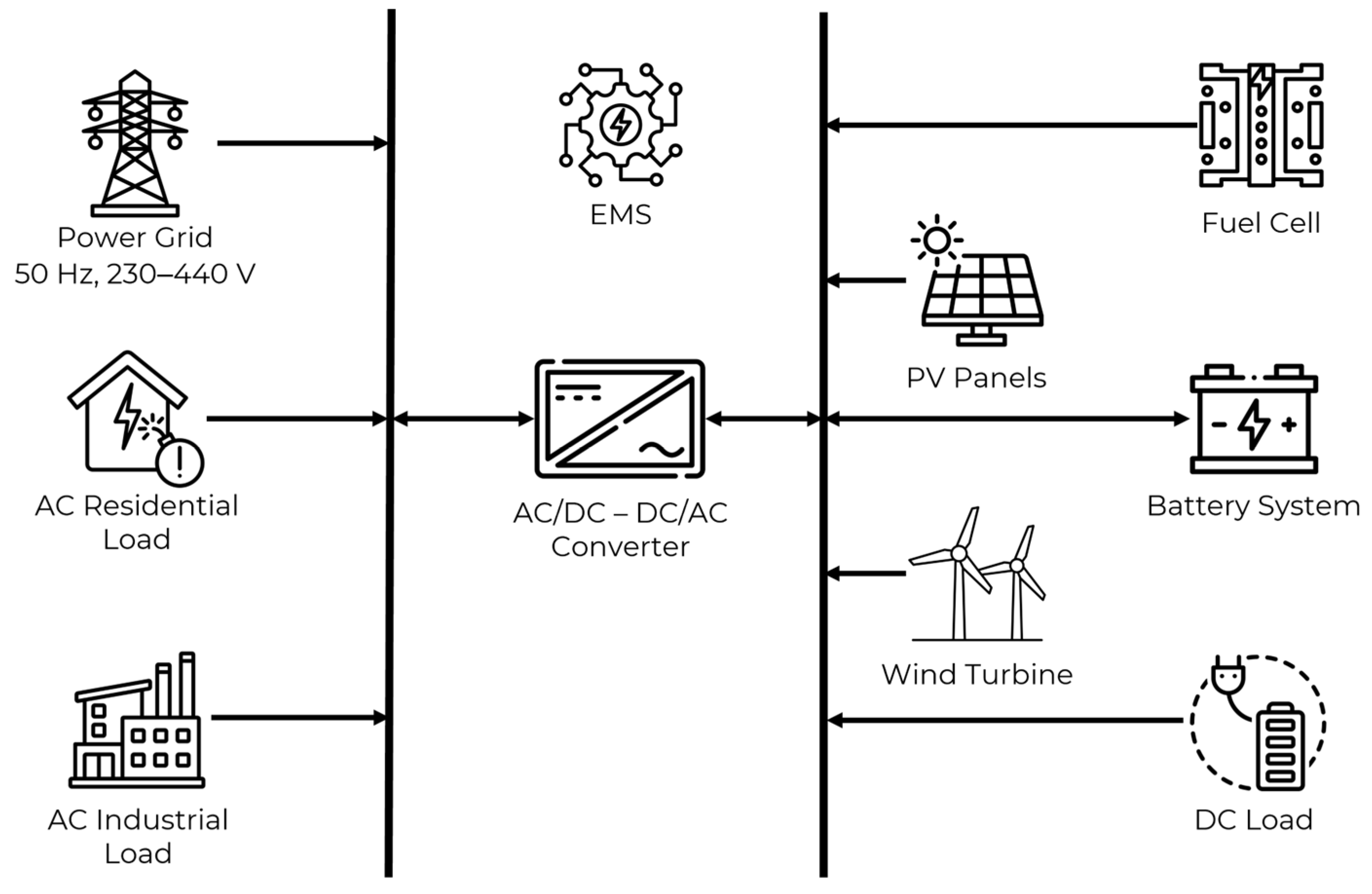
The adopted hybrid AC/DC MG is designed with a 400 V, 50 Hz point of common coupling (PCC) and a 750 V DC bus, enabling the integration of multiple DERs, storage devices, and loads. Its architecture is representative of real low-voltage networks, and it is located in the city of Reggio Calabria (Italy). Figure 1 describes the structure of the adopted hybrid AC/DC microgrid.
The remainder of the paper is structured as follows: Section 2 details the methodology, the fuzzy control design, and the performance indicators adopted for PQ analysis. Section 3 describes the hybrid AC/DC microgrid structure and its components, including generation units, storage, and load modelling. Section 4 presents and discusses the simulation results, evaluating the effectiveness of the fuzzy EMS in improving PQ and reducing operating costs. Finally, Section 5 summarizes the conclusions, highlights the novelty of the approach, and outlines directions for future research, including experimental validation and extension to larger-scale systems.

2. Materials and Methods

2.1. General Framework

The methodology adopted in this study aims at ensuring both PQ and efficient operation in a hybrid AC/DC MG that integrates renewable and dispatchable units. The workflow is articulated in four steps: (i) definition of PQ indicators, (ii) measurement architecture and signal processing, (iii) design and implementation of the fuzzy EMS, and (iv) validation through MATLAB R2024b/Simulink© scenarios. The approach is modelled in Simscape Electrical using a physical-network approach, where each component is represented by its constitutive equations and interconnected through Kirchhoff’s laws. This framework captures resistive losses, nonlinearities, and transient dynamics with higher fidelity, as the solver automatically handles the underlying differential-algebraic equations (DAE). The fuzzy EMS is designed to deal with the stochastic variability of RES and loads, offering robust decision-making without relying on precise system models. Input variables (e.g., PV and wind power, AC/DC loads, battery state of charge, and dynamic tariffs) are collected via MATLAB/Simulink© functional blocks and processed in real time.
To reduce the computational load while preserving electrical fidelity, the 24-h operating profile of irradiation, wind speed and load demand was compressed temporally into 24 s of simulation. The compression was applied only to the slowly varying envelopes of the environmental and demand profiles, while the electrical subsystem (switching devices, network equations and 50 Hz fundamentals) was solved with a native time interval of 20 µs (10 kHz sampling). This guarantees that phenomena in the frequency domain, harmonics, and transient responses are captured accurately. To verify that the adopted scaling does not distort the spectral content, additional simulations were performed with different compression factors (Section 4.8, Table 7).
All simulations were performed in MATLAB R2024b using Simulink and Simscape Electrical Toolbox on a workstation equipped with an Intel® Core™ i7-8550U processor (1.80 GHz) and 12 GB RAM. The complete model of the hybrid AC/DC microgrid required approximately 3 h for setup and parameter tuning and about 35 min of simulation runtime for a 24-h equivalent scenario. The computational complexity of the fuzzy EMS is very low: each inference cycle (rule evaluation and defuzzification) takes about 5–10 μs per simulation step, corresponding to a ratio of approximately 1:1000 between controller processing time and electrical system dynamics, thus ensuring real-time compatibility. The selected day is representative of the entire month of June in Reggio Calabria (Italy), chosen to avoid rainfalls or extreme weather events, thus ensuring reproducibility of the results over longer time horizons.

2.2. Power Quality Indicators

PQ assessment in hybrid AC/DC MG requires a multidimensional set of indicators to ensure compliance with international standards (e.g., IEC 61000, IEEE 1159) [75,76]. Individual isolated indicators do not account for the interactions between conversions, loads, and accumulation. Voltage deviation (ΔV) measures the deviation of the root mean square (RMS) value from the nominal value. Voltage must remain within ±10% of the nominal reference to avoid malfunction of end-user equipment (Equation (1)) [77].
V ( t ) = V P C C ( t ) V n o m V n o m · 100   [ % ]
In the adopted model, the reference is 230/400 V for AC and 750 V for DC, which represents a typical value for low-voltage DC microgrids. This setup provides efficiency in power conversion and compatibility with commercial converters and storage systems [78]. The protection of devices requires maintaining the voltage within predetermined limits to avoid overvoltage-induced insulation stress, overheating, or malfunction of power electronics. Frequency deviation (Δf) quantifies the deviation from the 50 Hz synchronous grid. According to the ENTSO-E guidelines [79], deviations must remain within ±0.2 Hz during normal operation [80]. Excursions exceeding the value determined by the regulations threaten stability and could trigger load detachment (Equation (2)) [81].
f ( t ) = f ( t ) f n o m
THDV summarises the impact of harmonic components on voltage and current. Converters and switching devices introduce distortions in both voltage and current waveforms, which must remain below 5% (voltage) to comply with IEC 61000-3-2 [82] (Equation (3)) [83].
T H D V ( % ) = h = 2 H V h 2 V 1 · 100
High values indicate converter stress and potential incompatibility with sensitive loads. While current THD provides an overview of waveform distortion, it may overestimate distortion impact during low current operation. For a more realistic evaluation, Total Demand Distortion (TDD), defined as the ratio of harmonic current to the maximum demand current according to IEEE 519 [84], is adopted (Equation (4)).
T D D ( % ) = h = 2 H I h 2 I L · 100
where Ih values are the RMS harmonic currents and IL is the maximum 15-min RMS demand current over the simulated day.
Active/reactive power balancing is determinant for limiting apparent currents and losses and for preserving the local grid’s injection capacity. Maintaining the instantaneous balance between P and Q is a determinant for stability. Power factor (PF) deviations lead to an increase in apparent power, losses, and a reduction in the MG’s hosting capacity (Equation (5)).
P g e n + P g r i d = P l o a d + P l o s s + d E s t o r d t
Finally, short-term event continuity indices, such as voltage dips, surges, and transients, measure the system’s resilience to transient events and the EMS’s ability to protect critical loads. The combination of these indicators provides a comprehensive framework to evaluate both technical compliance and end-user service quality. Their thresholds, summarized in Table 1, serve as reference values for the EMS to prioritize corrective actions during simulation scenarios.
The harmonic analysis was carried out using FFT-based post-processing of voltage and current signals sampled at 10 kHz (Δt = 100 µs), consistent with the electrical subsystem’s native solver step. To avoid aliasing, a fourth-order low-pass anti-aliasing Butterworth filter with a 2.5 kHz cutoff was applied before spectral decomposition. Each FFT was computed over a 10-cycle (200 ms) Hanning window, corresponding to 5000 samples, with 50% overlap between consecutive windows to ensure temporal continuity and reduce leakage effects. The windowing is synchronous with the 50 Hz fundamental frequency, and the Hanning window minimizes spectral leakage of converter switching components around integer harmonics. THDV and individual harmonic components were computed as per IEC 61000-4-7 and IEEE 519 standards [84,88].
For TDD evaluation, the harmonic RMS current Ih was obtained from the same FFT data, while the reference current IL represents the maximum 15-min RMS demand current over the equivalent 24-h profile. Since the 24-h period is compressed to 24 s, the 15-min integration window was proportionally scaled to 15 milliseconds (15 min/3600 s × 24 s = 0.1 s) to preserve the ratio between long-term and instantaneous values. RMS currents were computed using a moving-window RMS estimator equivalent to the standard’s averaging period. Validation runs with different compression factors (1×, 24×, 48×) confirmed that THDV and TDD deviations remained within ±0.2% of the full-time simulation, ensuring that the time compression does not distort spectral results.
All harmonic analyses were performed with double-precision arithmetic, and FFT-based spectra were verified against discrete Fourier transform (DFT) results from the Simscape Powergui block, showing agreement within 1%. These parameters guarantee that PQ indices are calculated in accordance with IEC 61000-4-7/4-30 and IEEE 519 requirements [84,89].

2.3. Measurement Architecture

The measurement architecture is not limited to detecting voltages and currents at strategic points in the MG but constitutes a level of observation for capturing complex phenomena [90]. The ability to integrate physical sensors with digital processing blocks in Simulink MATLAB© allows for the combination of experimental accuracy and modelling flexibility [91]. This aspect is important in a hybrid MG for the interactions between the AC and DC domains, because they generate transient effects that are not always describable with static parameters or RMS values. The use of the dq0 transform allows three-phase quantities to be represented in a rotating reference frame, making a clear separation between active and reactive components possible [92]. In practice, this approach converts sinusoidal AC quantities into quasi-DC signals, simplifying both control and analysis.
This choice is not only functional for control but also has a value that allows for a clearer study of dynamic power variations and the attribution of observed disturbances to specific operating conditions of the converters and loads [93,94]. In this way, measurement becomes a tool for causal analysis and not just descriptive monitoring [95]. Another important aspect concerns the temporal coherence of the signals. Synchronisation between sensors and processing units ensures high temporal resolution, which is necessary for the correct evaluation of PQ indices, particularly THDV, TDD and service continuity. The availability of high-frequency data allows for the capture of phenomena typical of power electronic systems, such as switching ripple or asymmetries in bipolar DC configurations, which would otherwise be missed by an analysis based solely on time averages. From a scientific perspective, the proposed architecture is therefore configured as a virtual laboratory where measurement is intimately linked to modelling. This not only provides input data to the fuzzy EMS but also helps validate control choices through the direct correlation between quality indices and system dynamics. The measurement layer, implemented in Simulink MATLAB©, combines physical sensors and numerical processing blocks. Each subsystem is equipped with voltage and current sensors: at the PCC, the DC bus, the PV array, the WT, the fuel cell, the battery, and the grid interface. Signals are converted into the Simulink MATLAB© domain through PS-Simulink MATLAB© Converter blocks and routed using Goto/From tags for modular reuse within the EMS. Derived quantities include instantaneous active and reactive power. The latter is obtained through the dq0 transformation, which maps three-phase AC signals into a rotating reference frame, enabling decoupled control and analysis of active (P) and reactive (Q) components. In steady state, the following relations, Equations (6) and (7) hold:
P = 3 2 ( v d i d + v q i q ) ,  
Q = 3 2 ( v q i d v d i q )
where vd and vq denote the dq components of the three-phase voltages obtained through the park transformation, and id and iq are the corresponding dq components of the three-phase currents. The Park transformation is adopted because it converts sinusoidal three-phase quantities into DC-like variables in a rotating reference frame, thus simplifying the control and analysis of AC systems [96]. In this framework, the d-axis represents the direct component aligned with the rotating reference frame, while the q-axis is the quadrature component orthogonal to it. Their cross-multiplication allows a decoupled and instantaneous calculation of active and reactive power.

2.4. Energy Management System (EMS)

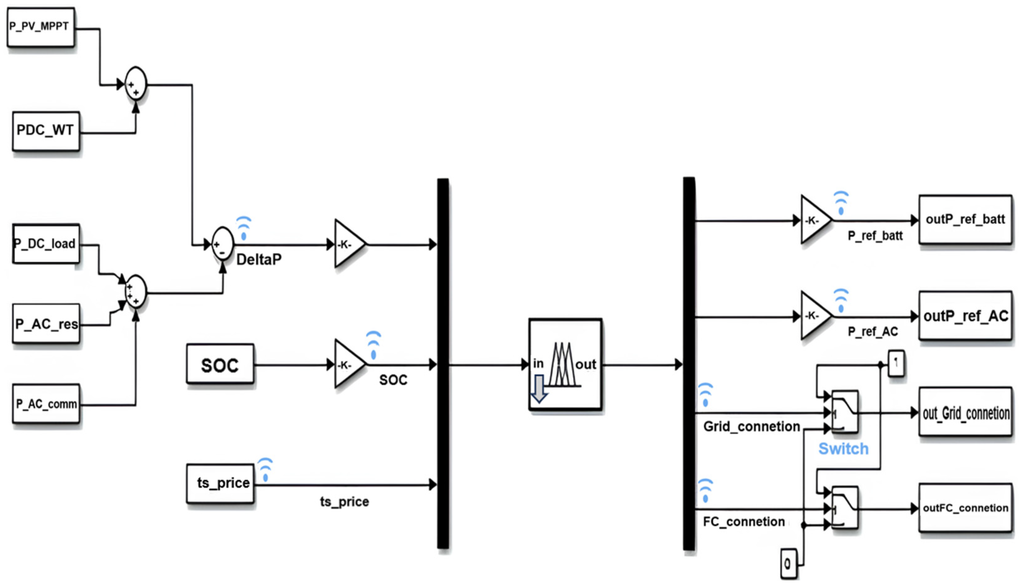
The EMS supervises the hybrid AC/DC MG by coordinating PV and WT, storage (battery), dispatchable generation (fuel cell), and grid exchange. Its objectives are: (i) maximizing renewable self-consumption, (ii) respecting technical and operational constraints, (iii) improving PQ indices, and (iv) minimizing operating costs under dynamic tariffs. While conventional centralized or rule-based strategies often lack flexibility and robustness, fuzzy logic control provides an adaptive, nonlinear, and uncertainty-resilient framework. This paradigm is particularly suited to MG, where renewable variability, stochastic loads, and market signals cannot be precisely modelled. Inputs to the fuzzy controller include the net power imbalance between generation and demand, the battery SOC, and the hourly electricity tariff. Based on these, the EMS generates four key outputs: (i) reference power for the battery converter (positive for discharge, negative for charge), (ii) reference power for the AC side via the bidirectional AC/DC converter, (iii) grid connection/disconnection command, and (iv) fuel cell activation signal. The EMS structure, implemented in MATLAB/Simulink (Figure 1), integrates functional blocks such as summation nodes for ΔP, normalization gains, multiplexers/demultiplexers, and switches with thresholds to convert continuous outputs into binary logic for grid and fuel cell control. The core is the Fuzzy Logic Controller block, designed in the Fuzzy Logic Designer app and exported as a .fis file into the Simulink workspace. Through this design, the EMS, described in Figure 2, ensures that surplus renewable energy is either stored or injected into the grid depending on SOC and tariff conditions, while deficits are covered by the battery, the fuel cell, or the grid according to cost-effectiveness and PQ constraints.

2.5. Fuzzy Controller Structure

The EMS controller is implemented as a Mamdani-type fuzzy inference system (FIS) [97], designed in MATLAB’s Fuzzy Logic Designer and exported into Simulink MATLAB©. This choice allows nonlinear decision-making based on heuristic rules, suitable for uncertain and time-varying MG conditions. The model considers three input variables: ΔP, SOC and the energy time-of-use signal (TOU). Each of these quantities is characterised by fuzzy sets defined through triangular membership functions, which allow for the translation of numerical values into qualitative descriptions. The ΔP is implemented within the range [−150; +150] kW, which corresponds to the maximum expected imbalance between total generation (PV, WT, FC) and the load profile in the adopted microgrid. The ΔP is classified as negative, zero, or positive. The SOC variable has been considered within the range [30, 90]%, reflecting the safe operating limits of the battery subsystem: the lower threshold at 30% prevents deep discharge and premature degradation of the battery, while the upper limit at 90% corresponds to full charge. The SOC is divided into increasing levels: low, medium, high, and very high. The electricity tariff, considered within the range [0.05; 0.15] €/kWh, reflects the variability of dynamic prices typically observed in the Italian electricity market. The electricity tariff is distinguished into low, medium, and high price bands. The controller outputs, on the other hand, concern four fundamental decisions: the reference power for the bidirectional battery converter (Pref_batt), the reference power for the AC/DC interface (Pref_AC), the connection status to the main grid, and the activation of the fuel cell (FC_connection). In this case as well, the membership functions are defined to ensure gradualness and computational simplicity. The Pref_batt (−100 to +100 kW) can take on charging, discharging, or idle values. The Pref_AC (from 0 to 150 kW) is modulated across three power levels. The network connection and fuel cell activation are managed as Boolean variables (0–1), derived from the fuzzy process using activation thresholds. The choice of binary values is motivated by the discrete nature of these operations, which in practice correspond to either activating or deactivating the respective device. In this way, the entire decision space of the MG is represented by a coherent set of linguistic rules that connect operating conditions to control actions. The system design strikes a balance between model accuracy and computational lightness, allowing the controller to operate in real-time and react flexibly to unexpected situations. The fuzzy inference engine is implemented as a Mamdani-type system, where rules are evaluated using max–min composition [98], and outputs are defuzzified through the centroid method [99]. This approach, validated in the literature, produces smooth and continuous control signals, particularly effective for variables such as Pref_batt and Pref_AC. In addition to the fuzzy logic, the controller enforces component-level protections. For the battery, SOC is constrained within 30–90%, and a maximum C-rate of ±5 kW is imposed to limit charge/discharge stress through the bidirectional DC/DC converter. Internal resistance and thermal effects are modelled in MATLAB/Simulink© (Simscape Electrical), version R2024b, using variable parameters [100], ensuring realistic dynamic behaviour. For the fuel cell, operational constraints include ramp-rate limits and warm-up times before connection to the DC bus, which prevent degradation of the electrochemical stack and auxiliary subsystems. For the converters, both DC/DC and AC/DC stages are subject to current and thermal limits defined by device ratings; duty cycles are internally saturated within [0–0.99] to protect switching devices, while PI controllers regulate duty cycles under these constraints to guarantee stable operation. At the PCC, PQ thresholds are imposed in compliance with international standards: voltage deviation ΔV within ±10% of nominal, frequency deviation Δf within ±0.2 Hz, and THDV limits of 5% and TDD limits of 8%. Whenever these limits are exceeded, corrective EMS actions such as grid reconnection or selective load shedding are triggered to preserve stability.
This integrated design ensures that the fuzzy EMS captures both the flexibility of heuristic decision-making and the robustness of hardware protection, achieving a balance between model accuracy, computational lightness, and operational reliability.

2.6. Fuzzy Controller Design

The fuzzy controller is developed to map uncertain and time-varying inputs into robust and adaptive control actions for the hybrid microgrid. Its design consists of three main steps: definition of membership functions, construction of the rule base, and specification of the inference/defuzzification process. Table 2 summarizes the fuzzy EMS inputs, outputs, and membership functions.
The fuzzy decision-making process relies on a knowledge base of if–then rules that encode expert reasoning and operational priorities [101]. Approximately 80 rules cover the full range of system conditions, balancing energy autonomy, cost-effectiveness, and PQ enhancement.
Illustrative examples include:
  • Surplus management: IF SOC = High AND ΔP = Surplus AND Tariff = High THEN export to grid.
  • Deficit management: IF SOC = Low AND ΔP = Deficit THEN activate fuel cell.
  • Tariff-aware charging: IF Tariff = Low AND ΔP = Surplus THEN charge battery.
  • Tariff-aware import: IF Tariff = High AND ΔP = Balanced THEN avoid import.
  • Emergency condition: IF SOC = Very Low AND ΔP = Deficit THEN connect to grid AND activate fuel cell.
The complete rule base defines all possible combinations of ΔP, SOC, and Tariff states with corresponding outputs for the battery, AC interface, grid connection, and fuel cell. Table 3 presents a representative subset of the fuzzy rule base for the EMS.

2.7. Validation Scenarios

To assess the robustness of the EMS and the hybrid MG model, five representative simulation scenarios were defined to explore different operating conditions, stressing both technical and economic objectives:
  • Normal operation with high-RES availability: PV and WT supply most of the demand, while the battery operates in charge/discharge mode to smooth fluctuations. The EMS prioritizes self-consumption and limits grid interaction.
  • Islanding with critical loads: Upon disconnection from the main grid, the EMS ensures continuity for critical AC/DC loads. The battery and fuel cell provide backup, while non-critical loads may be shed to preserve stability.
  • Step load variations: Sudden increases and decreases in load are applied to test the EMS response and PQ stability. Indicators such as ΔV, Δf, THDV and TDD are monitored to evaluate transient resilience.
  • Low-RES availability: When renewable production is insufficient and SOC approaches its lower threshold, the EMS activates the fuel cell and imports power from the grid to maintain supply.
  • Dynamic tariff fluctuations: Time-varying electricity prices are introduced to verify the EMS’s ability to shift charging/discharging decisions. The controller minimizes costs by charging during low-price hours and exporting or avoiding imports during high-price periods.
These scenarios were selected as they represent the most critical and recurrent operating conditions of a hybrid AC/DC microgrid. They cover nominal operation, emergency islanding, fast load transients, renewable scarcity, and tariff variability, thus enabling validation of both the technical robustness (scenarios 1–4) and the economic effectiveness (scenario 5) of the proposed fuzzy EMS.

2.8. Evaluation Criteria

The performance is assessed according to a set of complementary criteria, combining technical, economic, and robustness perspectives.
  • PQ indices: ΔV, Δf, THDV and TDD are continuously monitored at the PCC. These parameters were selected because they represent the fundamental indicators of PQ as defined by IEC 61000, IEEE 1159, IEEE 519 and ENTSO-E guidelines. The international IEC/IEEE standards set the thresholds of ±10% ΔV, ±0.2 Hz Δf, 5% THDV and 5/8% TDD serve as a benchmark for PQ stability.
  • Event statistics: disturbance events, such as sags, swells, and interruptions, are recorded through dedicated counters. The frequency and duration of such events provide insight into the resilience of the EMS under transient operating conditions. Continuity indices quantify the EMS capability to preserve supply quality during short-term disturbances, a critical aspect for sensitive loads and for demonstrating compliance with IEEE 1159 recommendations.
  • Energy balance: the EMS is evaluated in terms of import/export exchanges with the grid, renewable self-consumption ratio, and battery cycling. These metrics were chosen because they highlight how effectively the controller maximizes local use of RES and optimises storage utilization.
  • Economic cost/benefit estimation: by considering dynamic tariffs, the EMS is tested for its ability to reduce operating costs. Metrics include cumulative energy cost, avoided purchases during high-price periods, and revenues from energy export during peak tariffs.
  • Robustness analysis: system performance is assessed under parameter variations, such as changes in load demand, renewable generation profiles, and component ratings. Robustness is confirmed when PQ indices and economic benefits remain within acceptable limits despite uncertainties.
Together, these criteria provide a holistic evaluation of the EMS, demonstrating its capability to maintain technical compliance, enhance economic efficiency, and ensure reliable operation under diverse and uncertain microgrid scenarios.

2.9. Computational Complexity

The computational burden of the proposed fuzzy EMS is minimal compared to the intrinsic dynamics of the hybrid AC/DC MG. Rule evaluation and defuzzification require 5–10 μs per simulation step. The dominant electrical dynamics of converters and network transients evolve on the order of milliseconds (10−3–10−2 s).
The resulting ratio of about 1:100–1:1000 confirms that the controller introduces negligible latency relative to system dynamics. Even when combined with PQ calculators (FFT-based THDV and TDD estimation, event counters, RMS monitors), the supervisory layer remains computationally lightweight. The most demanding operation, FFT-based harmonic analysis, is only applied to selected signals and over limited time windows, further reducing processing overhead.
This low complexity makes the controller suitable for real-time or embedded deployment. Platforms such as digital signal processors (DSPs), field-programmable gate arrays (FPGAs), or SOC devices can easily host the fuzzy EMS together with PQ monitoring modules. As a result, the methodology is compatible with practical hardware-in-the-loop testing and field implementation in smart microgrid controllers.

2.10. Limitations and Assumptions

Despite its effectiveness, the proposed EMS is subject to several limitations and simplifying assumptions that should be acknowledged:
  • Simplified component models: The battery and fuel cell are represented with reduced-order electrochemical and thermal dynamics. While sufficient for control validation, these models do not capture degradation mechanisms or detailed thermal behaviour, which could influence long-term performance.
  • Tariff signal as exogenous input: The electricity price profile is treated as an externally provided input. No forecasting or market participation mechanisms are included, and the EMS assumes perfect knowledge of tariff variations.
  • Indirect PQ improvement: The EMS improves PQ primarily through dispatch decisions (balancing power, managing SOC, activating the fuel cell). Advanced reactive power control or harmonic compensation is not implemented, leaving PQ enhancement partly indirect.
  • No advanced observers: SOC, THDV, TDD and PQ indicators are computed using direct measurements and robust filtering, without the use of observers (e.g., Kalman filters or neural estimators). While this avoids complexity, it may limit accuracy under sensor noise or faults.
Table 4 describes the impact on the results of the limitations and assumptions made in this study.
These limitations define opportunities for future work, including integration of detailed electrochemical/thermal models, incorporation of predictive market strategies, deployment of advanced PQ controllers, and use of intelligent observers for enhanced state estimation.

2.11. Justification for Model-Based Rather than Experimental Validation

The validation of the proposed hybrid AC/DC microgrid was performed through physical-network modelling in MATLAB/Simulink rather than experimental testing. This methodological choice stems from both technical and practical considerations. The system integrates heterogeneous distributed energy resources at community scale (150 kWp PV, 60 kW wind turbine, 200 kWh battery, 20 kW fuel cell, and 150 kVA bidirectional converters), whose full-scale experimental implementation would require high-power infrastructures, dedicated safety systems, and substantial investment beyond the available laboratory facilities. Furthermore, the primary goal of this work is to assess the effectiveness of the fuzzy-based Energy Management System (EMS) in coordinating distributed resources and improving power quality and economic performance under realistic operating conditions. These objectives can be reliably achieved through physical-network simulation, which allows a high-fidelity representation of converter dynamics, transient phenomena, and PQ indicators ΔV, Δf, THDV, TDD) in a fully controllable and repeatable environment compliant with IEC/IEEE guidelines.
Finally, the present model validation is conceived as an intermediate stage toward experimental deployment, paving the way for future Hardware-in-the-Loop (HIL) and real testbed implementation, as outlined in the future work. Therefore, the use of model-based testing should not be viewed as a methodological limitation, but as a necessary step to ensure reproducibility, safety, and scalability toward real-world applications.

2.12. Experimental Verifiability of Performance Indicators

The performance indicators adopted in this study, ΔV, Δf, THDV, TDD, PF, and continuity indices, are not limited to numerical evaluation. All these quantities can be directly measured and verified in a real hybrid AC/DC microgrid using standard power quality instrumentation and high-resolution data acquisition systems compliant with IEC 61000, IEEE 519, IEEE 1159, and EN 50160 standards.
In practical terms, the measurement architecture implemented in the MATLAB/Simulink model can be reproduced in an experimental setup by installing synchronized voltage and current transducers at key points such as the PCC, the DC bus, the converters, and the grid interface. When combined with high-sampling-rate data acquisition units (sampling rate ≥ 10 kHz), this configuration enables real-time computation of RMS quantities, harmonic spectra (THDV and TDD), ΔV and Δf, as well as short-term continuity events (sags, swells, and transients) through standardized event counters and time windows. The same formulations and threshold criteria used in simulation can therefore be directly applied to experimental data, ensuring consistent comparison between modeled and measured results.
For the DC domain, voltage and current measurements, including ripple and converter-related transients, can be performed using Hall-effect transducers and differential probes, while derived indices such as TDD on branch currents can be obtained through FFT or DFT-based spectral analysis. The corresponding limit values and computational methods remain aligned with the technical standards adopted in this study. Looking ahead, the experimental validation of the proposed fuzzy EMS and its associated performance indicators can be carried out in both hardware-in-the-loop (HIL) environments and pilot-scale microgrid testbeds, maintaining identical measurement points, sampling frequencies, signal processing procedures, and compliance thresholds. This approach guarantees reproducibility of the results and traceability of the system performance with respect to the technical and economic objectives demonstrated in the simulation study.

3. Microgrid Structure

The methodological framework described in Section 2 is implemented and validated on a detailed hybrid AC/DC MG model. This Section introduces the main elements of the modelled system—RES, storage units, power electronic converters, and network interfaces—together with their parametrization and operating constraints. The aim is to provide a comprehensive representation of the physical layer that underpins the EMS design and simulation studies presented in the subsequent sections.

3.1. Overview of the Adopted Hybrid AC/DC Microgrid

The adopted hybrid AC/DC MG has a renewable structure of a 150 kWp photovoltaic (PV) array, corresponding to approximately 270 commercial modules rated at 550 W each. This size was selected to represent a typical community PV installation in Southern Italy, with rooftop and small ground-mounted PV systems. The PV subsystem is modelled through the single-diode equivalent and regulated by a DC/DC boost converter equipped with perturb-and-observe (P&O) MPPT, which stabilizes the output voltage at the 750 V DC bus. Complementing the PV generation, a 60 kW WT is included, characterized by cut-in and rated wind speeds of 3–4 m/s and 12 m/s, respectively, and a cut-out at 25 m/s. The selected capacity is representative of medium-scale wind machines frequently adopted in hybrid community microgrids. Its output is rectified through a diode bridge and further conditioned by a dedicated DC/DC converter before being injected into the DC bus. A 20 kW proton exchange membrane fuel cell (PEMFC) is integrated to support resilience during renewable scarcity. The stack operates at a nominal voltage of 48–50 V and is modelled considering activation, ohmic, and concentration losses. The size of the PEMFC was dimensioned to cover the essential loads rather than the full demand. Its output is elevated to the DC bus level via a DC/DC boost converter, and its operation is constrained by ramp-rate and warm-up dynamics. The flexibility of the system is provided by the battery energy storage system, rated at 200 kWh of capacity and 100 kW of power. This sizing corresponds to approximately 2–3 h of autonomy for the adopted load profile and is consistent with commercial lithium-ion storage units available at the community scale. The storage unit follows an Rint model with open-circuit voltage dependent on the SOC and is interfaced through a bidirectional buck–boost DC/DC converter. Operational limits are set within a 30–90% SOC window to prolong battery lifetime, while the overall round-trip efficiency is assumed at 85–90%. The link between the AC and DC subsystems is realized by a 150 kVA bidirectional voltage source converter (VSC), which can operate in grid-following mode when the MG is connected to the utility, or in grid-forming mode during islanded operation. The converter includes an LC filter at the AC side to reduce harmonic distortion and is responsible for regulating active/reactive power exchange as well as ensuring voltage and frequency stability at the PCC. The load profile combines different demand categories representative of community-scale applications. The residential AC demand reaches a peak of approximately 50 kW during evening hours with nearly unity PF. The commercial/industrial AC demand peaks at 45 kW during daytime, with an average PF of 0.9 and reactive demand up to 15 kvar. In addition, DC loads directly connected to the 750 V bus contribute up to 15 kW of variable demand [102].

3.2. Microgrid Elements

To provide a detailed representation of the hybrid AC/DC MG, each subsystem was modelled based on its physical principles, control strategies, and interface requirements. The following subsections describe renewable generation units, dispatchable fuel cells, battery storage, and power electronic converters that interconnect the sources, loads, and the external grid. This breakdown highlights the operational role of each component, the modelling assumptions adopted, and the constraints considered in the overall design of the energy management system.

3.2.1. PV Subsystem

The PV array is modelled using the single-diode equivalent circuit, which captures the nonlinear I–V characteristics of a solar cell. The output current is expressed as Equation (8) [103]:
I P V = I p h     I 0 ( e q ( V P V   +   I P V R s ) n k T     1 )     V P V   +   I P V R s R s h
where I p h is the photocurrent proportional to irradiance, I 0 is the diode reverse saturation current, R s is the series and shunt resistances, and n is the diode ideality factor.
The output power is Equation (9) [104]:
P P V ( t ) = V P V ( t ) · I P V ( t )
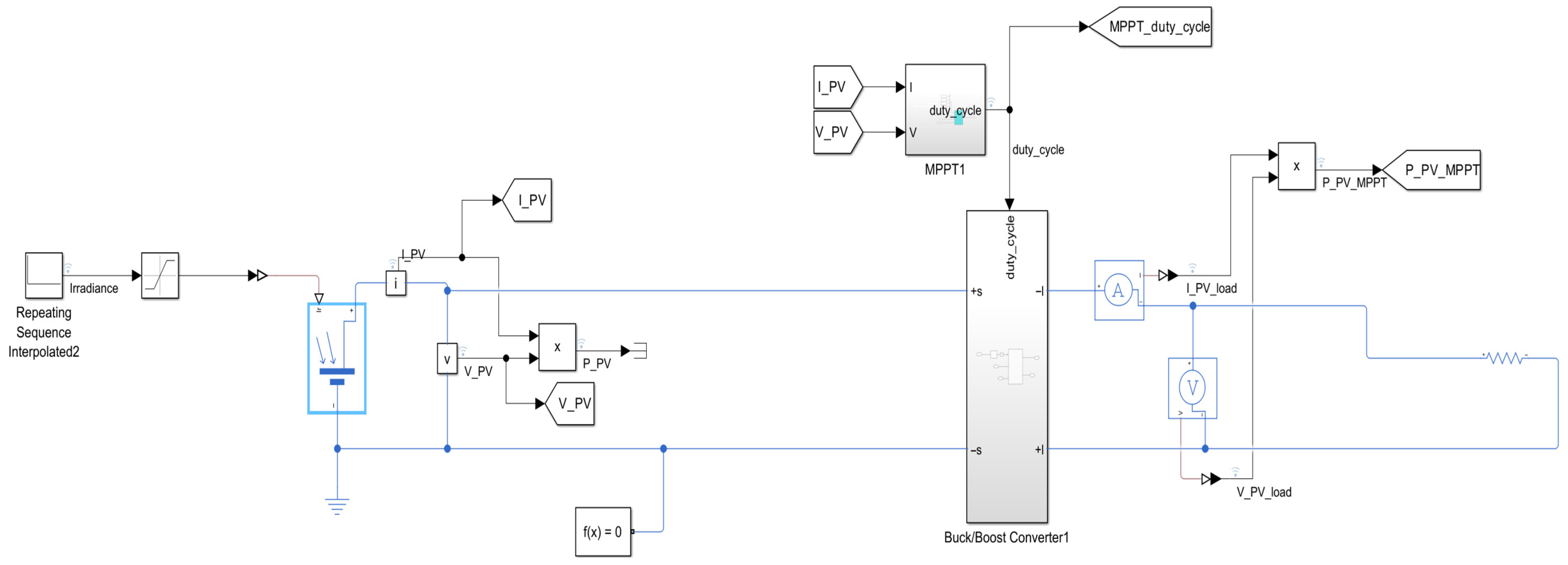
To maximize energy extraction, the PV subsystem is interfaced with a DC/DC boost converter, regulated by the Perturb & Observe (P&O) Maximum Power Point Tracking (MPPT) algorithm. The duty cycle D is iteratively adjusted by comparing successive measurements of output power: if a perturbation in voltage leads to an increase in power, the duty cycle is further adjusted in the same direction; otherwise, it is reversed. This simple yet robust strategy allows the converter to continuously track the maximum power point (MPP) under variable irradiance and temperature conditions. The PV field is dimensioned according to standard test conditions (STC: 1000 W/m2, 25 °C). Each solar cell is characterized by an open-circuit voltage of 0.5–0.6 V and a short-circuit current density of 30–40 mA/cm2. Cells are connected in series and parallel to form commercial PV modules, whose parameters—open-circuit voltage, short-circuit current, temperature coefficients, and number of cells per string—are set in the Solar Cell block of Simscape Electrical. The array configuration is designed to match the DC bus requirements of the hybrid MG, providing a nominal output power in the order of several tens of kilowatts. This ensures compatibility with the battery storage subsystem and with the expected load demand of the case study. The boost converter and MPPT controller are tuned to guarantee efficient operation under dynamic irradiance and temperature profiles.
The PV subsystem implemented is described in Figure 3.

3.2.2. Wind Turbine (WT) Subsystem

The WT converts wind kinetic energy into mechanical shaft power. The aerodynamic power captured by the rotor is given by Equation (10) [105]:
P w i n d = 1 2 ρ A v 3 C P ( λ ,   β )
where ρ is the air density, A is the rotor swept area, v is wind speed, and C P is the power coefficient (function of tip speed ratio λ and pitch angle β ).
The maximum theoretical C P is bounded by the Betz limit ( C p ,   m a x = 0.593 ). The turbine exhibits the typical four operating regions: (i) start-up, overcoming inertia; (ii) cut-in speed (4 m/s), when production begins; (iii) rated power at 12 m/s, where nominal output is achieved; and (iv) cut-out speed (25 m/s), where the turbine disconnects for safety. The shaft power drives a generator modelled with its electromechanical dynamics (Equation (11)) [106]:
J d ω r d t = T m     T e     B ω r
with inertia J , mechanical torque T m , electromagnetic torque T e , and damping B .
The electrical output is rectified and interfaced to the DC bus through a DC/DC converter.
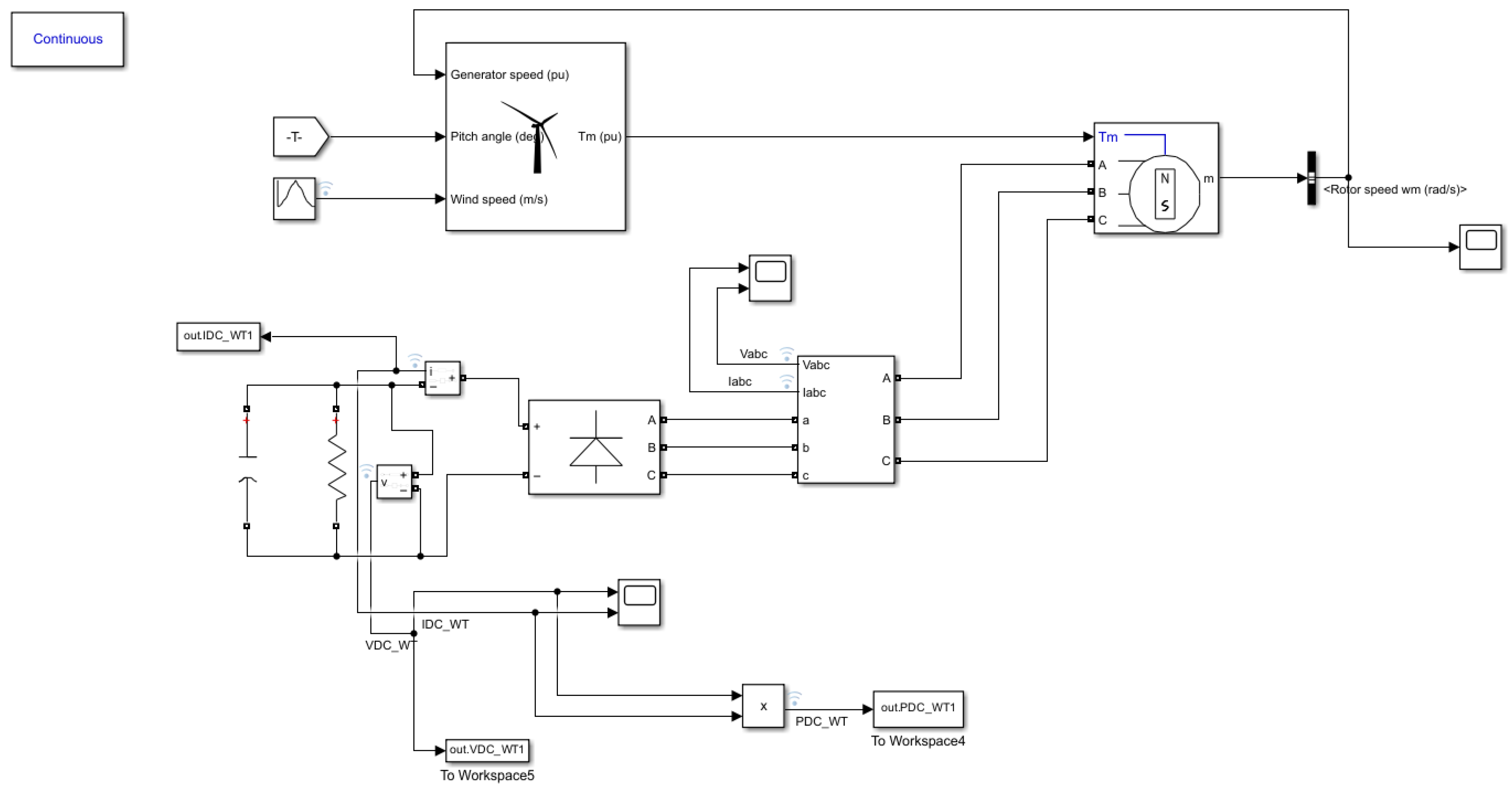
The generator’s three-phase AC output is rectified through a diode bridge (Universal Bridge), producing a pulsating DC voltage. A 1 µF capacitor and a 100 Ω resistor connected at the rectifier output act as a filter to smooth voltage ripple and stabilize the simulation. A downstream DC/DC converter regulates the voltage to match the DC bus level required by the microgrid.
The turbine is dimensioned as a small-to-medium-scale system (tens of kilowatts), suitable for community-level hybrid microgrids. The wind profile is provided as a daily time series (e.g., Reggio Calabria case study), ensuring realistic variability for PQ analysis.
The WT subsystem is described in Figure 4.

3.2.3. Fuel Cell (FC) Subsystem

The fuel cell (FC) subsystem is modelled as a Proton Exchange Membrane Fuel Cell (PEMFC). The FC converts hydrogen and oxygen into electricity via redox reactions (Equations (12)–(14)) [107]:
A n o d e : H 2     2 H +   +   2 e
C a t h o d e : 1 2 O 2 + 2 H + + 2 e     H 2
H 2 + 1 2 O 2     H 2 O + e n e r g y
The open-circuit voltage of a single cell is derived from the Nernst Equation (15) [108]:
E   =   E 0   +   R T 2 F   ln ( p H 2 · p O 2 1 / 2 p H 2 O )
Polarization losses (activation, ohmic, concentration) are included in the cell model, yielding the output voltage (Equation (16)) [109]:
V F C   =   N   ·   ( E     V a c t     V o h m     V c o n c )
where N is the number of cells in series.
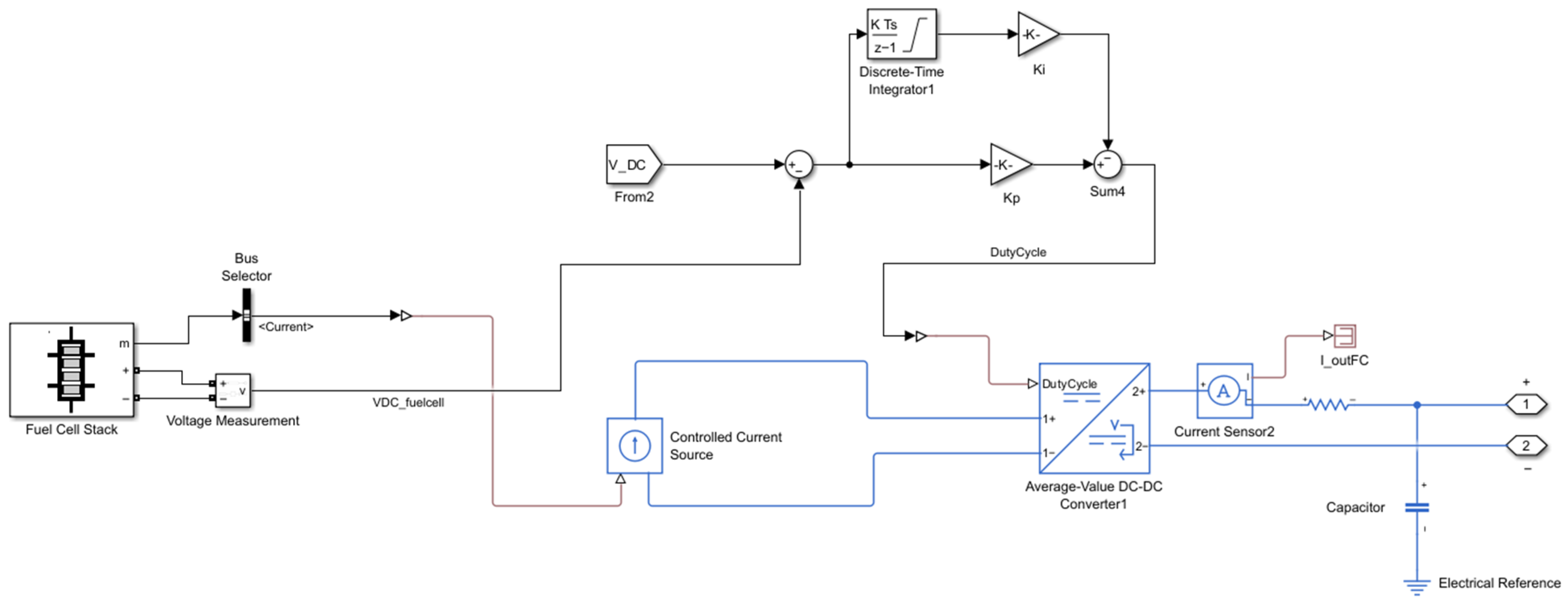
The FC stack is configured with a nominal voltage of 50 V, achieved through the series connection of elementary cells. Its rated power output is in the range of a few kilowatts, consistent with the hybrid MG’s scale. Polarization curves (V–I) are used to characterize performance, identifying the safe operating region that avoids mass transport limitations. To connect to the DC bus, the FC output is regulated via a DC/DC Boost converter, modelled with an average-value approach. A PI controller adjusts the duty cycle based on the error between the DC bus reference voltage and the FC output. A small series resistance (10−3 Ω) is included to emulate internal resistance and stabilize the simulation numeric. Operational constraints include maximum current limits, ramp-rate restrictions, and warm-up requirements to prevent degradation of the electrochemical stack.
The FC is connected to the DC bus via a unidirectional DC/DC converter, enabling controlled dispatch (Figure 5).

3.2.4. Battery Storage Subsystem

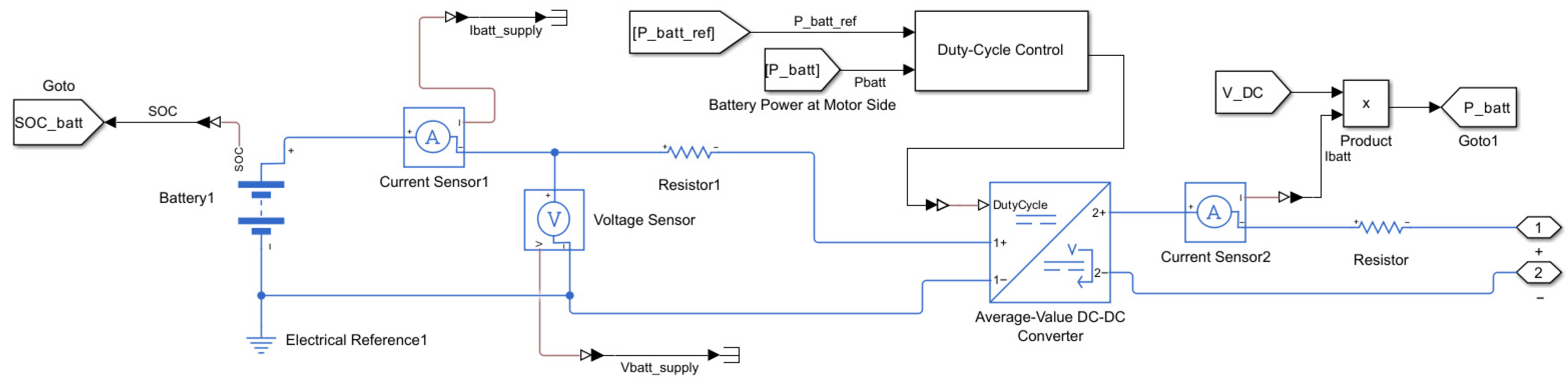
The battery acts as a buffering element that balances generation–load mismatches and supports PQ during transients. In the model, the storage unit is parameterized from a commercial Li-ion product and interfaced to the DC bus through a bidirectional Buck/Boost DC/DC converter governed by a PI regulator; the EMS decides charge/discharge according to ΔP, SOC and tariff signals. Continuous monitoring of SOC prevents deep discharge/overcharge and guides dispatch choices between storage, grid import/export, and fuel-cell activation. The battery is represented by the Rint model, which includes an open-circuit VSC and an internal resistance R0. The SOC is updated dynamically (Equation (17)) [110]:
S O C ( t ) = S O C ( 0 )     1 Q N 0 t I b a t t ( τ ) d τ
where Q N is the nominal capacity.
The storage interfaces the DC bus via a bidirectional Buck/Boost stage; a PI controller regulates the duty cycle to meet the DC-bus reference while obeying converter/device ratings (current and thermal limits). This average-value implementation ensures numerically stable simulation and realistic closed-loop dynamics for charge/discharge transitions commanded by the EMS [SOCmin, SOCmax].
Within the fuzzy EMS policy, the battery absorbs surplus RES (raising SOC) and supplies deficit periods before resorting to fuel-cell activation or grid import, with the choice modulated by tariff signals. This policy is explicitly framed in the thesis discussion on tariff-aware dispatch and SOC-driven decisions.
The battery storage subsystem is presented in Figure 6.

3.2.5. Power Electronic Converters

Power electronic converters are essential for integrating heterogeneous sources, storage units, and loads within the hybrid AC/DC microgrid. They provide voltage regulation, MPPT, bidirectional energy flow, and synchronization with the main grid. The PV subsystem employs a boost converter, while the battery subsystem uses a bidirectional buck–boost converter for charging/discharging. The governing equations are Equation (18) [111]:
V o u t ,   b o o s t = V i n 1     D ,   V o u t ,   b u c k   = D · V i n
where D is the duty cycle. Duty cycles are controlled via PWM signals generated by PI regulators.
A three-phase Voltage Source Inverter (VSI) is used to supply AC loads. Its dynamic behaviour is represented in the dq reference frame, enabling decoupled control of active and reactive power. A sinusoidal PWM scheme is implemented, with PI regulators adjusting modulation indices to maintain voltage and frequency stability.
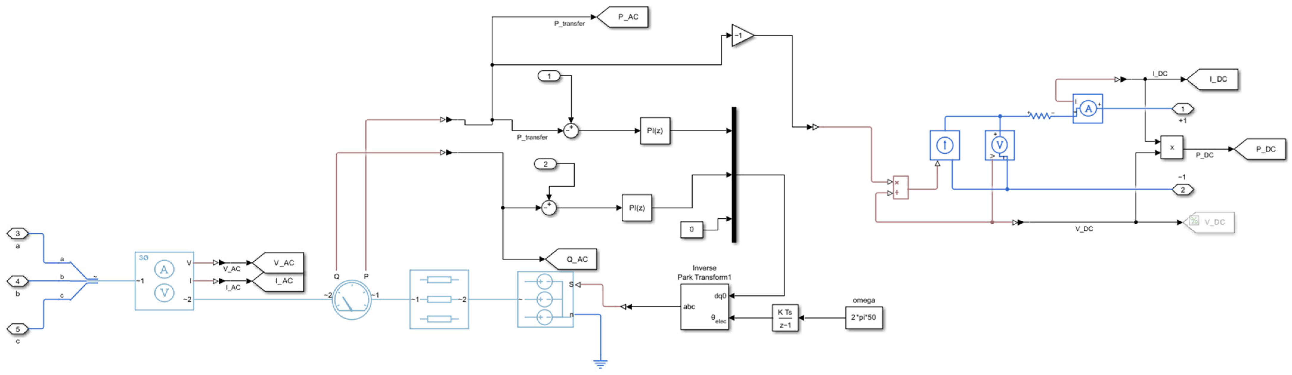
This converter interconnects the AC and DC buses and provides the interface with the main utility grid. In grid-connected mode, it regulates the PCC voltage and ensures synchronization with grid frequency. In islanded mode, it switches to grid-forming control, maintaining local voltage and frequency within PQ standards. Switching logic is implemented via EMS commands, ensuring smooth transitions between operating modes.
All converters are subject to thermal and current ratings. Saturation of duty cycles (0–0.99) is applied to prevent overmodulation and protect switching devices. LC filters are included at inverter outputs to limit harmonics and ensure compliance with PQ standards.

3.2.6. Load Models

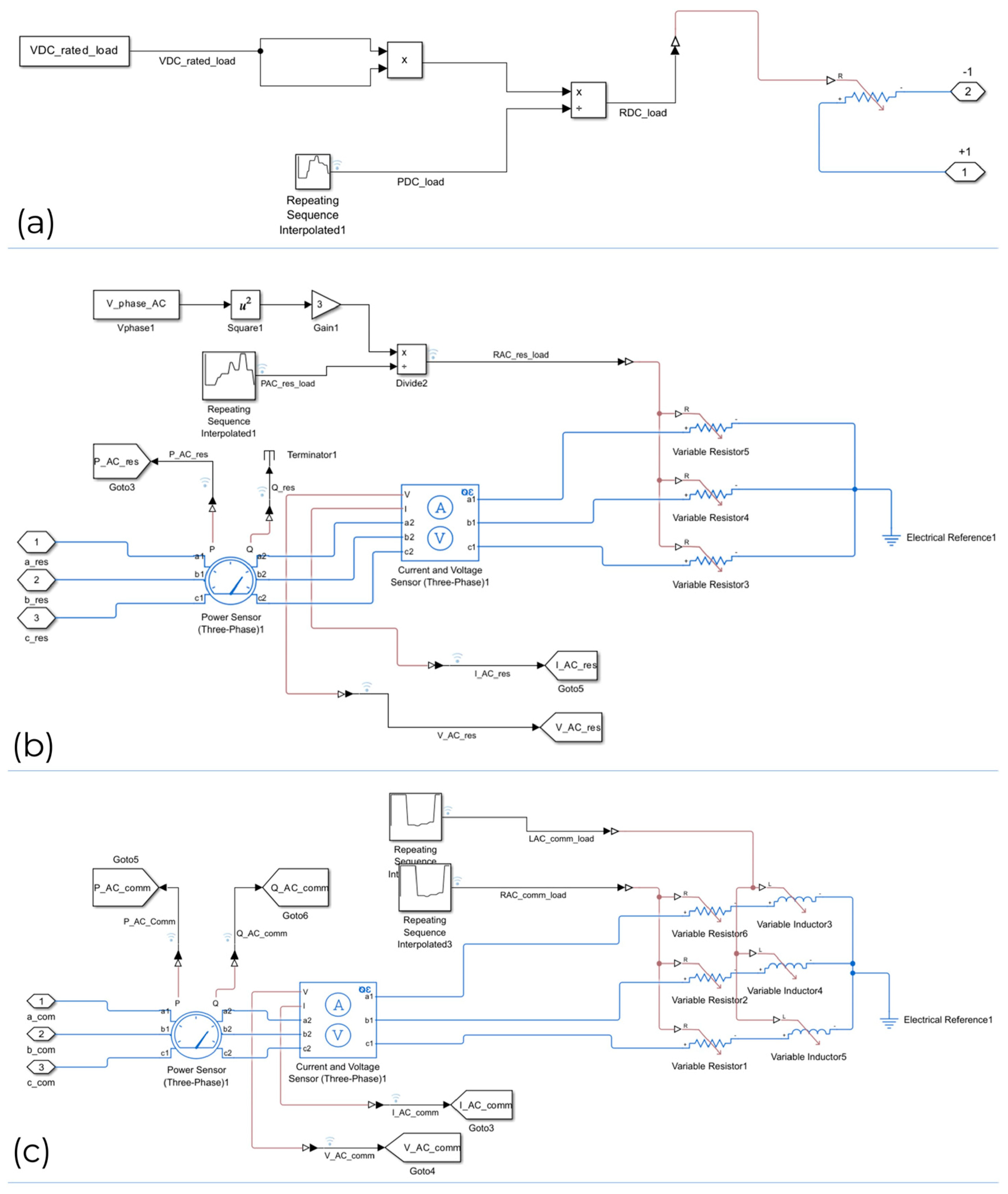
The hybrid MG supplies heterogeneous demand profiles, modelled as a combination of DC and AC loads with distinct temporal behaviours. This diversity ensures that the EMS is tested under realistic operating conditions. DC load is represented by a variable resistance connected to the DC bus, emulating typical electronic equipment and power electronics demand. The resistance varies dynamically according to a predefined profile, creating time-varying current demand directly from the DC subsystem. AC residential load is modelled as a single-phase resistive–inductive (R–L) equivalent connected to the AC bus. The daily profile peaks during evening hours, consistent with household usage patterns (lighting, appliances). The load exhibits both active and reactive components, requiring the EMS to manage PF and PQ indices. AC commercial/industrial loads are implemented as a three-phase time-dependent impedance, combining resistive and reactive elements. The load profile is highest during daytime working hours, with significant active and reactive power consumption. This component increases the stress on PQ indicators, especially THDV, TDD and ΔV, when connected in parallel with renewable sources and converters. The simultaneous presence of DC, residential AC, and commercial AC loads guarantees that the EMS must coordinate multi-domain energy flows while preserving PQ. This allows robust validation of the controller under realistic microgrid demand conditions.
The load models implemented are presented in Figure 7.
Recently, data-driven regression approaches, such as Gaussian process regression (GPR), have also been applied to modelling complex physical behaviours. The study [112] demonstrated the potential of GPR for advanced modelling activities in power supply systems by characterising the dielectric permittivity of materials with high accuracy and generalisation capabilities.

3.3. Grid Interface and PCC

The interfacing of the hybrid MG with the public grid is achieved through a PCC-located bidirectional AC/DC converter. The bidirectional AC/DC converter is mandatory to achieve a good quality of power and smooth mode transition from grid-connected and islanded modes of operations. It becomes accountable for local voltage and frequency retention at PQ standards, supplying critical loads with the aid of battery and fuel cell subsystems. Concerning PQ monitoring, the CCP acts as the reference point for PQ indices (ΔV, Δf, THDV, TDD) measurement. In grid-connected mode, the converter operates in grid-following control, synchronising with the grid frequency and regulating the voltage PCC. The exchange of active and reactive power is regulated based on EMS commands, allowing the microgrid to import energy during RES deficits or export excess generation when rates are favourable. In island mode, in case of disconnection from the public grid, the inverter switches to grid-forming control. It becomes responsible for maintaining local voltage and frequency within PQ standards, powering critical loads with the support of battery and fuel cell subsystems regarding PQ monitoring at the PCC. The bidirectional AC/DC converter at the PCC, shown in Figure 8, illustrates the two operating modes.

3.4. Summary of Microgrid Components

Table 5 summarizes the principal components, models and converters used in the proposed model, including the key parameters and converter/interface description.

4. Results and Discussion

4.1. Simulation Setup

The hybrid AC/DC microgrid described in Section 3 was implemented in MATLAB R2024b—Simulink/Simscape Electrical©. Simulations were run over a 24-h horizon, compressed into 24 s of simulation time, allowing detailed observation of fast transients and slow energy dynamics within a manageable computational effort. Parameters such as solar irradiance, wind speed, load, and tariff profiles derived from realistic daily conditions in Reggio Calabria, Italy.

4.1.1. Solver Configurations

Each subsystem was assigned a dedicated solver for numerical stability:
  • The WT, modelled in Simscape Electrical—Specialized Power Systems—used Powergui Continuous mode to capture electromechanical dynamics accurately.
  • The fuel cell (FC) required Powergui Discrete mode with a fixed step of 5 × 10⁻⁵ s, ensuring proper resolution of switching dynamics in the DC/DC converter.
  • Other subsystems (PV, battery, converters, loads) were simulated with adaptive stiff solvers handling DAEs across the global model.

4.1.2. Environmental and Load Profiles

  • Solar irradiance: daily profile of June in Reggio Calabria, with a peak around 1000 W/m2 at midday.
  • Wind speed: empirical hourly profile, cut-in at 3–4 m/s, rated at 12 m/s, cut-out at 25 m/s, with afternoon peaks up to 12–14 m/s.
  • Loads: total demand representative of 12 residential households and 2 commercial/industrial users, with evening peaks for residential and daytime peaks for commercial/industrial loads.
  • Tariffs: dynamic pricing ranging between 0.05 and 0.15 €/kWh, influencing EMS cost-driven decisions.

4.1.3. Simulation Stability and Load Variation Management

Several simulation measures were adopted to guarantee numerical and dynamic stability under variable load and current conditions. Each power electronic converter was equipped with current and thermal protection limits (duty cycle saturation between 0 and 0.99, rated current constraints, and LC filters) to prevent oscillations and overcurrent phenomena. PI controllers were tuned to achieve critically damped responses for both voltage and current loops, avoiding overshoot during step load variations. The fuzzy EMS Scope actively compensated for power imbalances by modulating the reference powers of the battery converter and the AC/DC interlinking converter, effectively smoothing transient currents, and maintaining power quality indices (ΔV, Δf, THDV, TDD) within IEC/IEEE standard limits. Step-load and islanding tests were explicitly simulated to validate the controller’s robustness: the DC bus voltage remained within ±2% of nominal, and converter currents settled within 50 ms after each disturbance. Solver configurations (Powergui Continuous for the wind turbine and Discrete with a 5 × 10⁻⁵ s step for the fuel cell) ensured numerical stability and convergence during high-frequency switching events. These combined control and numerical strategies effectively prevented current instability and mitigated the impact of abrupt load variations throughout the 24-h simulation cycle.

4.1.4. Data Management

Selective signal logging was enabled to reduce computational load, focusing on voltages, currents, instantaneous powers, duty cycles, SOC, and PQ indices (ΔV, Δf, THDV, TDD). Outputs were post-processed using Simulink Data Inspector and stored in the MATLAB Workspace for EMS decision-making.

4.1.5. Case Studies

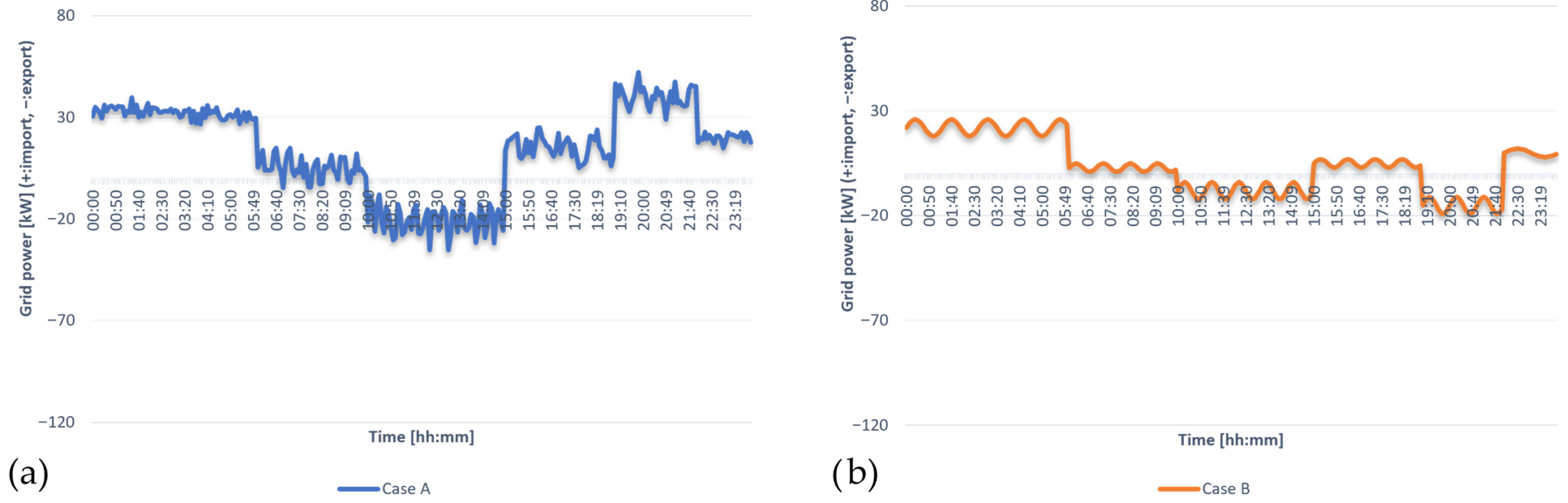
Two case studies were defined:
  • Case A (baseline): microgrid operated without fuzzy EMS, relying only on local converter controls.
  • Case B (proposed): microgrid managed by the fuzzy EMS, coordinating RES, storage, FC, and grid interface.
This setup provides the basis for comparing PQ performance, energy balance, and economic efficiency under realistic daily operating conditions.

4.2. Renewable Generation Profiles

The hybrid microgrid integrates two renewable subsystems—PV and WT—with complementary production patterns. Their combined contribution ensures a diversified portfolio of generation, reducing dependence on a single resource and enhancing overall stability.
  • PV subsystem.
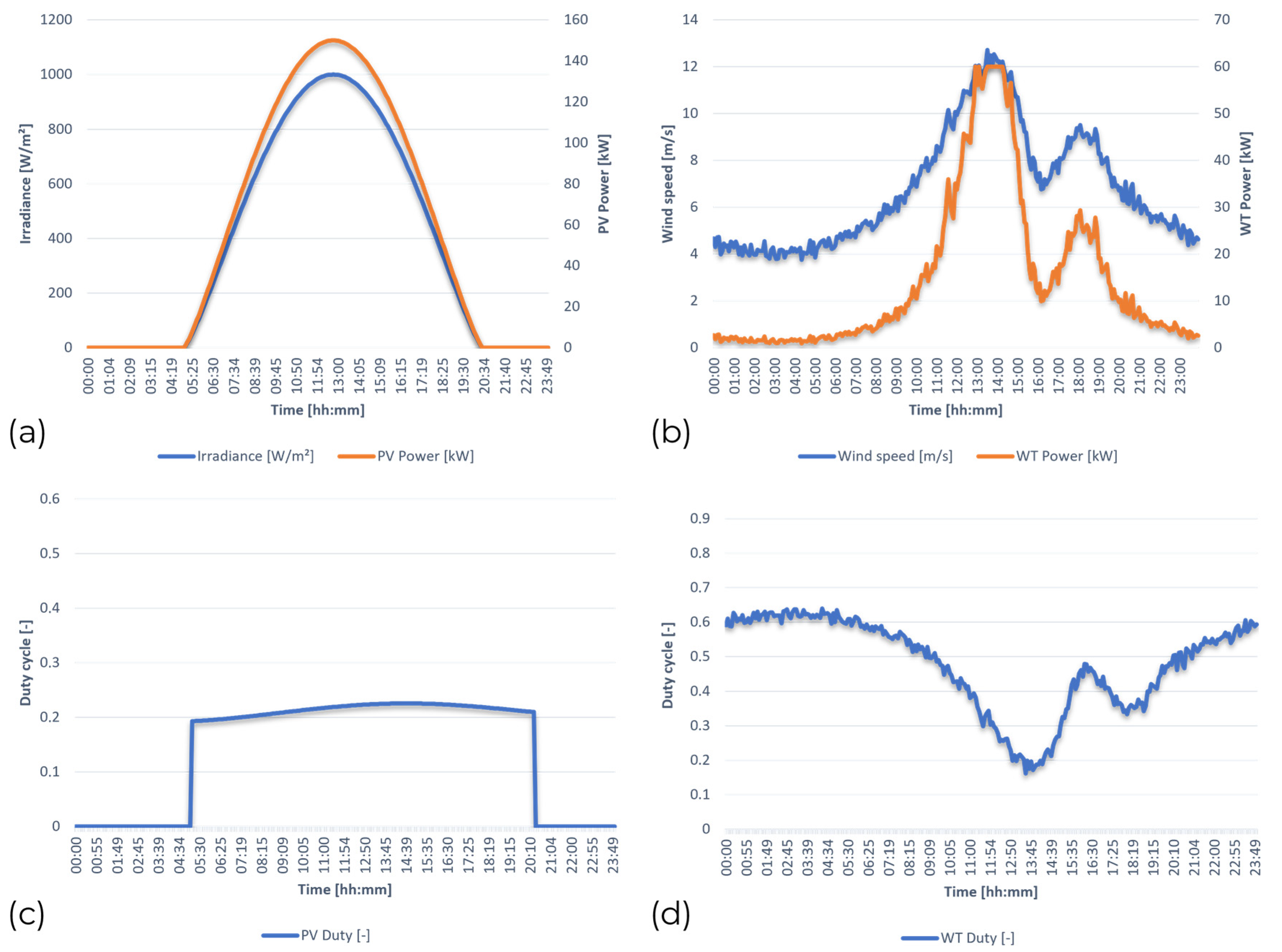
The PV array output is governed by solar irradiance, which follows a deterministic daily profile. On the considered June day in Reggio Calabria, irradiance peaks at 1000 W/m2 around noon, resulting in a maximum PV power of ~150 kW (Figure 9a). Production begins at sunrise, ramps up steadily until midday, and then decreases toward evening. This smooth and predictable curve ensures that PV dominates the generation mix during daylight hours. The MPPT P&O algorithm successfully tracks the maximum power point across all conditions, as evidenced by the converter duty cycle trajectory (Figure 9c). The MPPT efficiency remains high throughout the day, allowing the PV subsystem to operate close to its theoretical maximum.
  • WT subsystem.
Compared to PV, wind generation is inherently stochastic and less predictable. The WT subsystem is driven by hourly wind profiles, with speeds fluctuating between 3–14 m/s. The turbine reaches cut-in at ~3–4 m/s in the morning, operates near its rated region (~12 m/s) during the afternoon, and shuts down if exceeding 25 m/s. On the analysed day, average wind power results in a production with peaks of ~60 kW in the early afternoon (Figure 9b). Variability is more pronounced than for PV, with transient dips and surges that directly affect the DC bus. The rectifier–DC/DC stage modulates its duty cycle (Figure 9d) to stabilize the DC link, compensating for rapid fluctuations in aerodynamic power.

4.3. Load Profiles

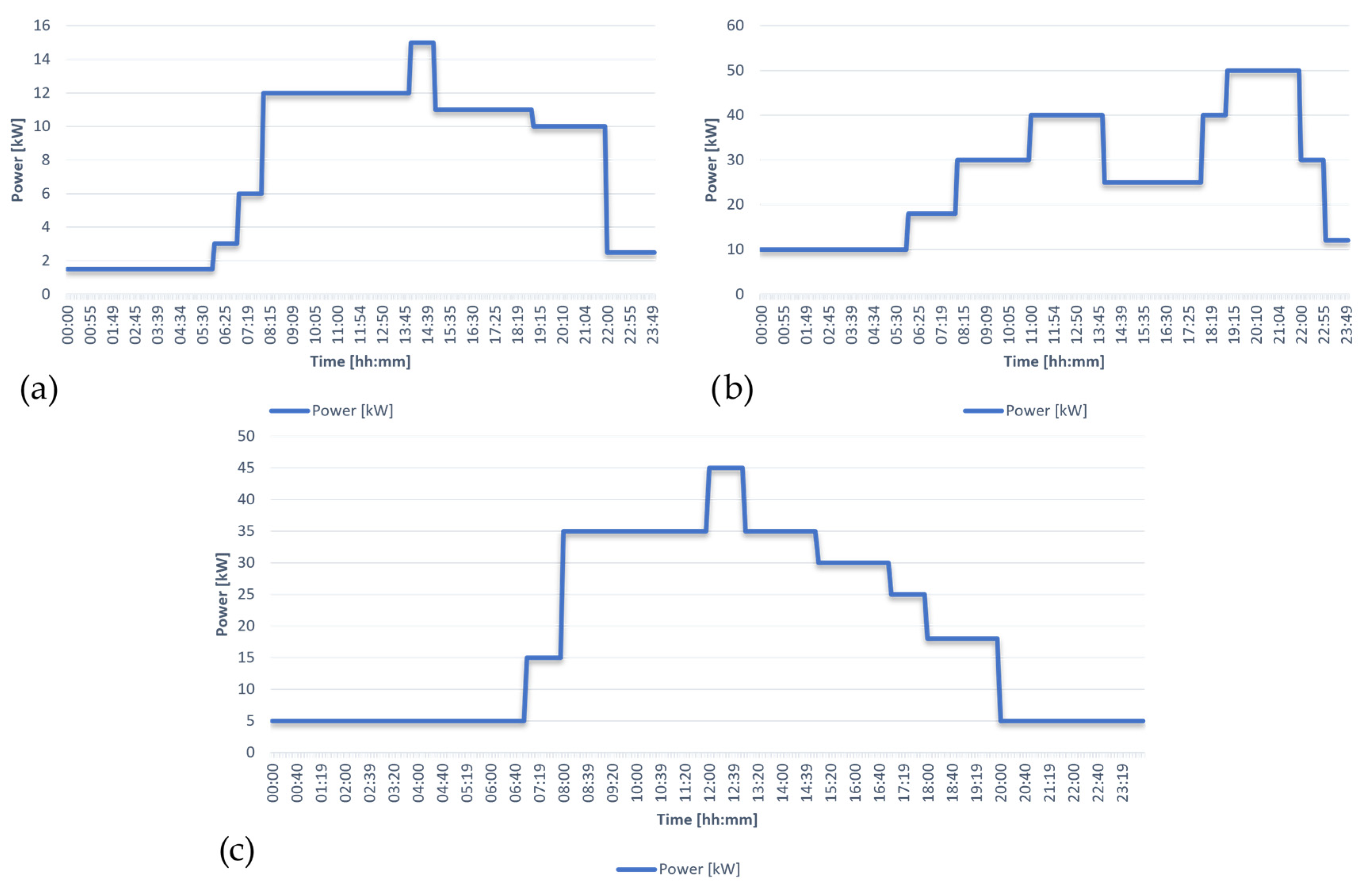
The hybrid microgrid demand is modelled as the superposition of DC, residential AC, and commercial AC loads, each characterized by distinct daily patterns (Figure 10).
  • DC load: Represents electronic and ICT equipment, such as LED lighting and server racks. It exhibits a variable demand with peaks of ~15 kW, supplied at a nominal voltage of 48 V. The equivalent resistance dynamically changes according to the power profile, ensuring a realistic representation in Simscape.
  • Residential AC load: Aggregated from 12 households, modelled with PF = 1. The profile shows two pronounced peaks: a midday peak of ~40 kW (11:00–14:00) and an evening peak of ~50 kW (19:00–22:00), consistent with typical household activity patterns. The remainder of the day is characterized by moderate consumption in the 10–20 kW range.
  • Commercial AC load: Represents 2 small/medium enterprises, modelled with PF = 0.9. Demand is concentrated during business hours (08:00–18:00), with an average active power of ~35 kW and peaks up to 45 kW. The reactive power demand reaches ~15 kVar, stressing PQ indices and testing EMS capability in reactive power balance.
The coexistence of DC, residential, and commercial loads generates complementary demand curves, with residential peaks aligning partially with PV production, while commercial loads overlap with business hours. This heterogeneity ensures that the EMS must coordinate resource dispatch across different domains and time horizons.

4.4. Fuel Cell Operation

The fuel cell (FC) subsystem operates as a dispatchable backup unit, activated only when renewable sources and the battery are unable to cover the demand.
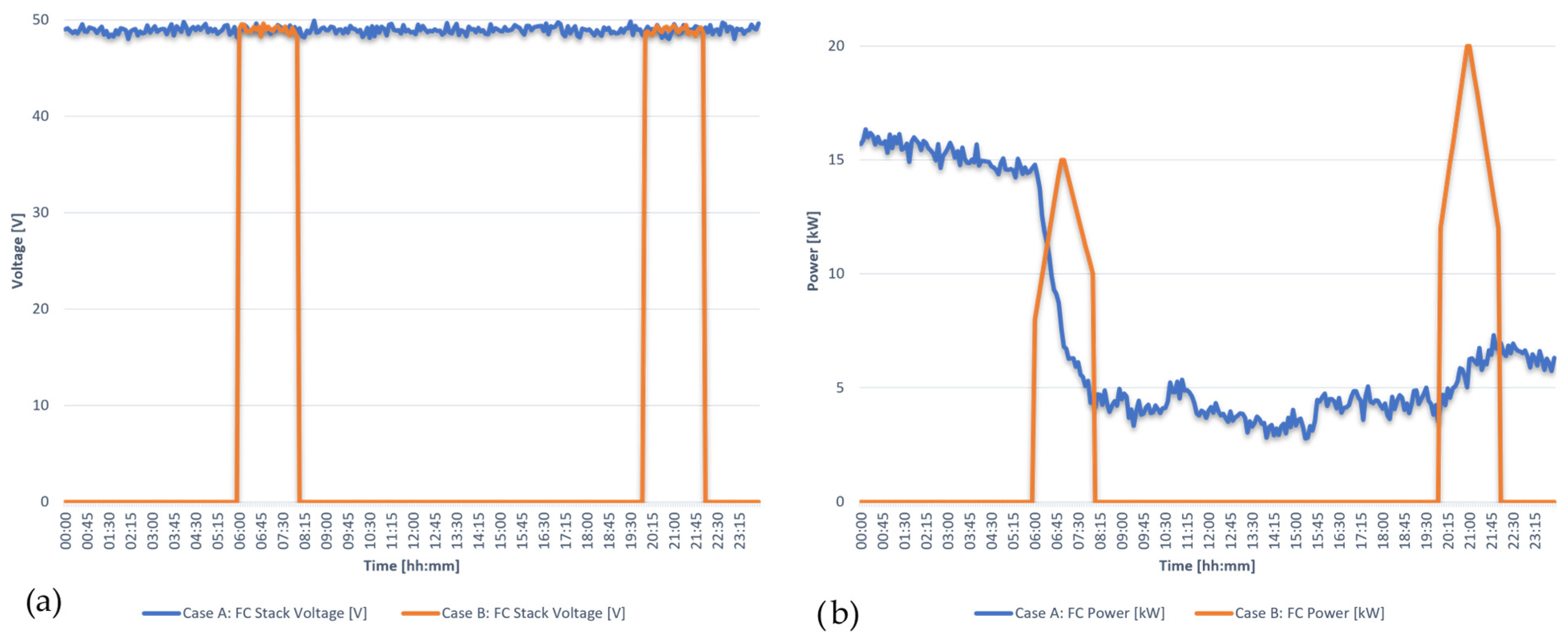
Stack voltage: The FC maintains a stable output voltage of 48–50 V throughout its operating range, consistent with the nominal configuration of the PEMFC stack (Figure 11a). Power output: The FC delivers power proportional to the load deficit not supplied by PV, WT, or the battery. During critical periods, such as early morning and evening hours with low RES and depleted SOC, the FC reaches an output of up to ~20 kW (Figure 11b).
  • Baseline (Case A, without EMS): The FC activates irregularly, with frequent switching events and variable output levels. This results in inefficient hydrogen utilization and accelerated degradation of the stack.
  • Proposed (Case B, with EMS): The fuzzy EMS schedules FC operation more selectively. The FC is activated only under critical conditions (negative ΔP combined with low SOC and high tariff), supplying demand in a controlled manner. This reduces the number of activations, limits hydrogen consumption, and extends system lifetime. These outcomes are consistent with the results reported in recent studies on fuzzy-logic-based energy management systems, which demonstrated similar benefits in enhancing power quality, improving fuel utilization, and reducing operational costs in hybrid AC/DC microgrids [113].
Overall, results show that the EMS improves fuel cell operation by aligning its activation with system-wide priorities, ensuring both technical reliability and economic efficiency.

4.5. Battery Storage Dynamics

The battery subsystem provides short-term balancing capability, compensating for the variability of PV and WT generation while respecting SOC and converter constraints.
  • Case A (baseline, without EMS): The SOC trajectory shows wide oscillations, frequently dropping below 20%, indicating harmful deep discharge cycles (Figure 12). Such operation increases stress on the Li-ion cells, accelerating degradation and reducing lifetime.
  • Case B (with fuzzy EMS): The SOC is maintained within a safer operational window, between 30% and 90% (Figure 12). The EMS schedules charging during midday RES surplus and discharging during evening deficits, avoiding unnecessary cycling. This strategy reduces depth-of-discharge, limits the number of cycles, and extends battery lifetime.
Temporal contribution: The battery provides the largest support in the evening hours, when RES is minimal and loads are high. During central daytime hours, the EMS prioritizes charging, storing excess PV and wind energy for later use.
Efficiency: The overall round-trip efficiency of the charge/discharge process is 85–90%, consistent with commercial Li-ion performance.
These results demonstrate the EMS capability to use the battery as a strategic buffer: smoothing short-term imbalances, reducing reliance on the fuel cell and grid, and lowering operational costs while preserving storage lifetime.

4.6. Energy Tariff Profile and EMS Decisions

  • Dynamic electricity prices were incorporated as an external input to test the economic responsiveness of the fuzzy EMS. The daily tariff profile fluctuates between 0.05 €/kWh (low price) and 0.15 €/kWh (high price) (Figure 13).
  • Low-price periods (0.05 €/kWh): The EMS prioritizes battery charging, absorbing surplus PV and WT generation or even importing from the grid if SOC is below its upper threshold. This strategy reduces costs by storing energy when it is cheapest.
  • High-price periods (0.15 €/kWh): The EMS avoids grid import and commands the battery to discharge or even export to the grid if SOC is sufficiently high. This behaviour increases revenues by selling energy during peak tariff windows.
  • Intermediate tariffs (0.10 €/kWh): The EMS balances between storage and direct supply to loads, minimizing unnecessary cycling of the battery.
Comparative behaviour: In Case A (without EMS), the system imports from the grid regardless of tariff, leading to higher costs. In Case B (with EMS), import is minimized and scheduled export is enabled during high-price intervals, resulting in lower daily energy cost and higher self-consumption rate.
These results confirm the ability of the fuzzy EMS to incorporate economic signals into its dispatch strategy, aligning energy flows with cost-optimization objectives.

4.7. Grid Exchange

The interaction with the utility grid at the PCC is strongly influenced by the presence of the fuzzy EMS.
  • Case A (baseline, without EMS): Grid power exchange is highly irregular, with frequent oscillations between import and export (Figure 14a). The system imports electricity even during high-tariff periods, leading to increased operational costs. This uncontrolled behaviour also stresses the PCC, potentially compromising PQ.
  • Case B (with fuzzy EMS): Grid interactions are smoother and better aligned with tariff signals (Figure 14b). The EMS minimizes imports during peak-price hours (0.15 €/kWh) and schedules exports when local generation exceeds demand and tariffs are favourable. As a result, daily imports are reduced by ~18%, while controlled exports provide additional economic benefit.
These results confirm that the fuzzy EMS effectively optimizes grid exchanges, reducing costs while maintaining technical compliance at the PCC.

4.8. Power Quality Analysis at PCC

The impact of the fuzzy EMS on PQ was assessed by comparing Case A (baseline, without EMS) and Case B (with EMS) at the PCC.
  • ΔV: In Case A, voltage fluctuations reached ±6% of the nominal value, occasionally exceeding IEC/IEEE limits. With EMS, deviations were confined within ±2%, ensuring compliance.
  • Δf: Without EMS, frequency control in islanded mode showed oscillations above 0.2 Hz from nominal. With EMS, the AC/DC interlinking converter maintained 50 Hz stability across all operating scenarios.
  • THDV: Case A exhibited THDV levels up to 7% under nonlinear load conditions, violating the 5% limit. Case B reduced THDV to below 3%, due to smoother dispatch and reduced converter stress.
  • TDD: Case A reached approximately 8%, while in Case B, it was maintained below 4%, well within the IEEE 519 limits
  • Continuity events: Case A recorded short sags and transient interruptions during load steps and source switching. Case B presented no PQ violations, with uninterrupted supply to critical loads.
These results confirm that the fuzzy EMS significantly enhances PQ at the PCC, maintaining all indices within international standard thresholds while improving system resilience.
To validate the adopted time-compression ratio, simulations were repeated with 1:24, 1:12 and 1:6 scaling factors. The resulting PQ indices showed deviations below 0.5% (Table 6), confirming that the adopted scaling preserves the harmonic and dynamic behavior of the hybrid MG.

4.9. Economic and Operational Benefits

The adoption of the fuzzy EMS yields both economic and operational advantages when compared with the baseline case.
  • Reduction of grid imports: Daily energy imports are reduced by ~18% in Case B, thanks to optimized scheduling of RES, battery, and FC dispatch. Controlled exports are enabled during high-tariff periods, increasing revenues.
  • Cost savings: By aligning charging with low-price hours (0.05 €/kWh) and discharging/exporting during high-price windows (0.15 €/kWh), the EMS reduces total daily operating costs by 10–15% compared with the baseline scenario.
  • Increased self-consumption: The share of local RES consumed within the microgrid rises significantly. The EMS coordinates PV and WT generation with load demand and battery storage, raising the self-consumption index from 62% in Case A to 78% in Case B.
  • Operational benefits: Smoother dispatch reduces stress on converters and mitigates PQ issues at the PCC. The battery undergoes shallower cycles (SOC maintained between 30–90%), extending its expected lifetime, while the fuel cell is used more sparingly and efficiently, lowering hydrogen consumption.
These results, described in Table 7, confirm that the fuzzy EMS provides a dual advantage: economic efficiency through tariff-aware scheduling and technical robustness via improved resource coordination. The hybrid AC/DC microgrid thus achieves higher autonomy, lower operational costs, and longer component lifetime.

4.10. Robustness and Sensitivity Analysis

To further validate the proposed EMS beyond the representative day analysis, a comprehensive robustness study was carried out as described below. To address the reviewer’s comment, the robustness analysis was extended to include multi-day simulations, Monte Carlo testing, and sensitivity studies on the main input parameters. In addition to the original representative day, four non-consecutive weeks were simulated (one for each season), using realistic residential load, photovoltaic, and wind generation profiles derived from meteorological and consumption data. A Monte Carlo campaign with 500 simulations was then performed, introducing uncertainties in the load and renewable generation profiles (Gaussian noise with a standard deviation of 10%), tariff forecasting errors (bias ±5%, random noise with σ = 5%, and a one-hour tariff slot shift in 10% of cases), and measurement noise on the controller inputs (0.5% RMS on voltage, 1% RMS on current, and ±1% offset on state of charge). For each scenario, performance indicators such as daily energy cost, imported energy, self-consumption, frequency deviation, THDV, TDD, and the number of SOC limit violations were evaluated, reporting the median, interquartile range, and 5th–95th percentiles, together with the CVaR95 of the cost and the probability of meeting power quality limits. A deterministic sensitivity analysis was also carried out by varying the tariffs (±10%, ±20%, ±30%), SOC limits (20–90%, 30–90%, 10–100%), and measurement noise level (0–2%) to assess system performance elasticity. Results show that the EMS maintains stable and compliant behavior in more than 96% of the scenarios, with a CVaR95 cost deviation limited to +8.4% compared to the baseline, an average THDV of 2.7% (maximum 4.6%), and an average TDD of 4.3%, all within the regulatory limits. The self-consumption remains above 92%, and SOC limit violations occur in less than 3% of the simulations. These results confirm the robustness and reliability of the proposed fuzzy-based control strategy under realistic operational uncertainties and parameter variations.

4.11. Discussion

The comparative evaluation between the baseline scenario (Case A) and the fuzzy EMS-controlled configuration (Case B) demonstrated the central role of supervisory intelligence in hybrid AC/DC microgrids. The results clearly indicate that the integration of renewable generation, storage systems, and flexible dispatch strategies cannot be effectively achieved without a higher-level controller capable of coordinating technical, economic, and operational objectives simultaneously.
From the perspective of renewable integration, the complementary generation of PV and wind sources was better exploited under the fuzzy EMS, reducing the variability of the combined profile, and ensuring a continuous energy supply without compromising PQ. In particular, dispatch smoothing reduced the exposure of the system to the stochastic fluctuations of wind production, while the PV generation, characterised by predictable peaks at midday, was efficiently stored or redirected to local loads.
The utilization of storage also revealed substantial improvements. In the uncontrolled scenario, deep battery cycles often reduced the state of charge below 20%, leading to accelerated degradation and diminished round-trip efficiency. Under fuzzy EMS coordination, the SOC was maintained within a controlled 30–90% band, which extended battery lifetime and preserved efficiency levels close to 90%. Similarly, the fuel cell subsystem was managed more selectively: instead of being continuously activated, it was employed only when necessary to support critical loads, thus reducing hydrogen consumption and avoiding frequent start–stop sequences that negatively affect the stack’s durability.
Economic performance was equally enhanced. The baseline case was characterized by uncontrolled imports and exports, with high dependence on the main grid during peak tariff periods. In contrast, the EMS-controlled case reduced imports by approximately 18% and synchronized exports with high-price windows, achieving a reduction in operating costs of 12.3% while simultaneously increasing renewable self-consumption from around 62% to nearly 78%. These findings confirm that tariff-aware fuzzy scheduling is an effective strategy to align system operation with cost minimization and autonomy goals. From the PQ perspective, the EMS played an indirect but decisive role. By smoothing dispatch and avoiding uncontrolled exchanges with the grid, the fuzzy controller ensured that voltage deviations remained within ±2%, frequency oscillations were suppressed around the 50 Hz nominal value, and harmonic distortion was reduced below 3%, all fully compliant with IEC/IEEE standards. These results demonstrate that PQ can be improved not only through active compensation devices but also through intelligent energy management strategies embedded at the supervisory level. The hybrid AC/DC microgrid model has been parametrized and validated for a Mediterranean case study (Reggio Calabria, Italy) with PCC 400 V–50 Hz and DC bus 750 V, using local RES profiles and IEC/IEEE PQ limits. Therefore, its quantitative results are representative of these conditions. However, the framework can be extended to other climates or operational contexts (e.g., desertic or marine environments) after proper re-parametrization of the following aspects: (i) RES profiles (irradiance, wind) and extreme events; (ii) thermal derating and soiling for PV; (iii) thermal and SOC operating ranges for BESS; (iv) wind turbine cut-in/cut-out parameters; (v) local grid standards (e.g., 60 Hz for naval systems) and PQ thresholds; (vi) inclusion of reactive power and harmonic control functions if required.
In desert environments, high temperature and dust conditions must be considered; in marine applications, humidity, salinity, and corrosion effects should be modelled. The fuzzy EMS remains applicable without structural changes but requires retuning of ΔP, SOC and tariff membership functions. Hence, the present study provides a proof of concept, while guidelines for model adaptation to desertic and marine contexts are outlined for future work.

5. Conclusions

This paper presented the modelling, implementation, and validation of a hybrid AC/DC microgrid equipped with a fuzzy-logic-based energy management system. The study integrates several functionalities, which consist of generating energy from renewable sources, electrochemical storage, a fuel cell subsystem, and tariff-based dispatching strategies. The entire system is coordinated by a supervisory controller implemented in MATLAB/Simulink. The fuzzy logic EMS developed and validated in this work effectively coordinated PV, WT, fuel cell and storage resources within a hybrid AC/DC microgrid. The simulation results showed stable operation, with voltage and frequency variations within regulatory limits (ΔV ≤ ±2%, Δf ≤ ±0.2 Hz) and a significant reduction in harmonic distortion (THDV < 3%, TDD < 5%). At the same time, daily operating costs were reduced by between 10% and 15% and self-consumption from renewable sources increased by approximately 16%. The results show how fuzzy EMS improves both technical and economic performance. PQ indices remain within international standards, ensuring reliable supply even under variable renewable generation and load conditions. The coordinated distribution of renewable energy avoided deep and damaging battery cycles, minimised hydrogen consumption and improved the overall efficiency of resource utilisation. The results validate fuzzy logic as an effective supervision approach for AC/DC hybrid microgrids. It combines robustness in the face of uncertainty, ease of implementation, and low computational requirements with tangible improvements in technical, economic, and operational terms. Compared to more complex methods, the fuzzy approach offers a balanced compromise between interpretability and performance, making it suitable for real-time embedded applications. Although the proposed model brings important advances in the energy field, the improvements in PQ obtained indirectly through distribution optimisation do not explicitly compensate for harmonics or reactive power. Future developments will therefore involve extending the EMS with dedicated PQ control functions, in particular, reactive power support and active harmonic mitigation.
The battery/fuel cell models were abstracted for simplicity and do not consider electrochemical degradation or heat dynamics; future work will incorporate complete models to capture lifetime influences and improve predictive maintenance schedules. Tariff signals were assumed to be fully known, but in truth, uncertainty and forecasting errors are inherent; therefore, future work will consider incorporating forecasting algorithms as well as adaptive tariff-aware optimization. In addition, the fuzzy rule base was set a priori, posing issues for scalability; future developments will consider the use of adaptive extensions (e.g., ANFIS or metaheuristic tuning) of membership functions for online adjustments.
Finally, the model was tailored for a single case study performed in Southern Italy; future work projects will demonstrate generic applicability by expanding the methodology for varied sites as well as using hardware-in-the-loop measurement and experimental campaigns. In short, although the current work confirms the efficacy of an EMS based on fuzziness for hybrid DC/AC microgrids, future improvement will focus on surmounting existing limitations by integrating advanced modelling, direct PQ regulation, adaptable intelligence, andpredictive features, as well as experimental verification.
The following research direction will improve the technical validity, economic optimality, and overall applicability of the suggested scheme to a significant extent. The improvements will narrow the gap between simulation experiments and on-site feasibility, establishing fuzzy logic as a mature, sustainable, and scalable technology for controlling contemporary DC/AC hybrid microgrids.

Author Contributions

Conceptualization, D.P. and F.L.F.; methodology, D.P., F.L., M.V. and A.J.; software, D.P. and A.J.; validation, D.P., M.V., D.F., S.V. and F.L.F.; formal analysis, D.P., F.L., S.V., M.V. and F.L.F.; investigation, D.P., M.V. and F.L.F.; resources, M.V., D.F. and F.L.F.; data curation, D.P., F.L., F.L.F. and M.V.; writing—original draft preparation, D.P., F.L., M.V. and F.L.F.; writing—review and editing, D.P., F.L., M.V. and F.L.F.; visualization, D.P. and F.L.; supervision, M.V., D.F., S.V. and F.L.F.; project administration, M.V.; funding acquisition, D.F. and F.L.F. All authors have read and agreed to the published version of the manuscript.

Funding

This work was funded by the Next Generation EU—Italian NRRP, Mission 4, Component 2, Investment 1.5, call for the creation and strengthening of “Innovation Ecosystems”, building “Territorial R&D Leaders” (Directorial Decree n. 2021/3277)—project Tech4You—Technologies for climate change adaptation and quality of life improvement, n. ECS0000009 (particularly, action 9 of Spoke 2—Goal 2.1—Pilot Project 1). This work reflects only the authors’ views and opinions; neither the Ministry for University and Research nor the European Commission can be considered responsible for them. This work has been supported by the University of Rijeka under the project number UNIRI-IZ-25-55.

Data Availability Statement

The original contributions presented in this study are included in the article. Further inquiries can be directed to the corresponding author.

Conflicts of Interest

The authors declare no conflicts of interest.

Abbreviations

RESRenewable Energy Sources
PVPhotovoltaic
PQPower Quality
EMSEnergy Management System
ESSEnergy Storage System
FLFuzzy Logic
MLMachine Learning
DRLDeep Reinforcement Learning
RLReinforcement Learning
ZEBZero-Emission Buildings
PEMFCProton Exchange Membrane Fuel Cell
SOCState of Charge
WTWind Turbine
DGDistributed Generation
MGMicrogrids
ACAlternating Current
DCDirect Current
MPCModel Predictive Control
ANNArtificial Neural Networks
THDTotal Harmonic Distortion
TDDTotal Demand Distortion
PCCPoint of Common Coupling
DERDistributed Energy Resources
FISFuzzy Inference System
TOUTime-of-Use
DSPsDigital Signal Processors
FPGAField-Programmable Gate Arrays
GPRGaussian Process Regression
MPPTMaximum Power Point Tracking
MPPMaximum Power Point
VSIVoltage Source Inverter
VSCVoltage Source Converter

References

  1. Yuvaraj, T.; Devabalaji, K.R.; Kumar, J.A.; Thanikanti, S.B.; Nwulu, N.I. A comprehensive review and analysis of the allocation of electric vehicle charging stations in distribution networks. IEEE Access 2024, 12, 5404–5461. [Google Scholar] [CrossRef]
  2. Ejuh Che, E.; Roland Abeng, K.; Iweh, C.D.; Tsekouras, G.J.; Fopah-Lele, A. The Impact of Integrating Variable Renewable Energy Sources into Grid-Connected Power Systems: Challenges, Mitigation Strategies, and Prospects. Energies 2025, 18, 689. [Google Scholar] [CrossRef]
  3. Karagiannakis, G.; Panteli, M.; Argyroudis, S. Fragility modeling of power grid infrastructure for addressing climate change risks and adaptation. Wiley Interdiscip. Rev. Clim. Change 2025, 16, e930. [Google Scholar] [CrossRef]
  4. Zhao, S.; Blaabjerg, F.; Wang, H. An overview of artificial intelligence applications for power electronics. IEEE Trans. Power Electron. 2020, 36, 4633–4658. [Google Scholar] [CrossRef]
  5. Zhao, Q.; Wang, L.; Stan, S.E.; Mirza, N. Can artificial intelligence help accelerate the transition to renewable energy? Energy Econ. 2024, 134, 107584. [Google Scholar] [CrossRef]
  6. Liu, X.; Qiu, L.; Fang, Y.; Wang, K.; Li, Y.; Rodriguez, J. Finite control-set learning predictive control for power converters. IEEE Trans. Ind. Electron. 2023, 71, 8190–8196. [Google Scholar] [CrossRef]
  7. Xu, S.; Huang, W.; Huang, D.; Chen, H.; Chai, Y.; Ma, M.; Zheng, W.X. A reduced-order observer-based method for simultaneous diagnosis of open-switch and current sensor faults of a grid-tied NPC inverter. IEEE Trans. Power Electron. 2023, 38, 9019–9032. [Google Scholar] [CrossRef]
  8. Zhang, J.; Tian, J.; Alcaide, A.M.; Leon, J.I.; Vazquez, S.; Franquelo, L.G.; Yin, S. Lifetime extension approach based on the Levenberg–Marquardt neural network and power routing of DC–DC converters. IEEE Trans. Power Electron. 2023, 38, 10280–10291. [Google Scholar] [CrossRef]
  9. Azizi, M.; Husev, O.; Mbayed, R.; Monmasson, E.; Martins, J.; Veligorskyi, O. Energy Router: A Sustainable Solution for Future Residential Buildings. IEEE Power Electron. Mag. 2025, 12, 75–86. [Google Scholar] [CrossRef]
  10. Aslam, M.U.; Shakhawat, N.S.B.; Shah, R.; Amjady, N.; Miah, M.S.; Amin, B.M.R. Hybrid Energy Storage Modeling and Control for Power System Operation Studies: A Survey. Energies 2024, 17, 5976. [Google Scholar] [CrossRef]
  11. Khan, M.Y.A.; Liu, H.; Yang, Z.; Wang, J.; Zhang, Y. Hierarchical control of microgrid: A comprehensive study. Electr. Eng. 2025, 107, 13681–13712. [Google Scholar] [CrossRef]
  12. Li, Y.; He, H.; Khajepour, A.; Chen, Y.; Huo, W.; Wang, H. Deep reinforcement learning for intelligent energy management systems of hybrid-electric powertrains: Recent advances, open issues, and prospects. IEEE Trans. Transp. Electrif. 2024, 10, 9877–9903. [Google Scholar] [CrossRef]
  13. Mbende, E.T.; Muluh, F.A.; Pesdjock, M.J.P.; Kenne, G.; Dagang, C.T.S.; Sonfack, L.L. A simple fuzzy logic-based DC link energy management system for hybrid industrial power supply. Energy Rep. 2023, 10, 3619–3628. [Google Scholar] [CrossRef]
  14. Miron, A.; Cziker, A.C.; Beleiu, H.G. Fuzzy Control Systems for Power Quality Improvement—A Systematic Review Exploring Their Efficacy and Efficiency. Appl. Sci. 2024, 14, 4468. [Google Scholar] [CrossRef]
  15. Al-Saadi, M.; Al-Greer, M.; Short, M. Reinforcement Learning-Based Intelligent Control Strategies for Optimal Power Management in Advanced Power Distribution Systems: A Survey. Energies 2023, 16, 1608. [Google Scholar] [CrossRef]
  16. Shaukat, N.; Islam, M.R.; Rahman, M.M.; Khan, B.; Ullah, B.; Ali, S.M.; Fekih, A. Decentralized, democratized, and decarbonized future electric power distribution grids: A survey on the paradigm shift from the conventional power system to micro grid structures. IEEE Access 2023, 11, 60957–60987. [Google Scholar] [CrossRef]
  17. Dev, A.; Kumar, V.; Khare, G.; Giri, J.; Amir, M.; Ahmad, F.; Prince, J.; Anand, S. Advancements and Challenges in Microgrid Technology: A Comprehensive Review of Control Strategies, Emerging Technologies, and Future Directions. Energy Sci. Eng. 2025, 13, 2112–2134. [Google Scholar] [CrossRef]
  18. Islam, M.M.; Yu, T.; Giannoccaro, G.; Mi, Y.; La Scala, M.; Rajabi, M.N.; Wang, J. Improving reliability and stability of the power systems: A comprehensive review on the role of energy storage systems to enhance flexibility. IEEE Access 2024, 12, 152738–152765. [Google Scholar] [CrossRef]
  19. Agha Kassab, F.; Rodriguez, R.; Celik, B.; Locment, F.; Sechilariu, M. A Comprehensive Review of Sizing and Energy Management Strategies for Optimal Planning of Microgrids with PV and Other Renewable Integration. Appl. Sci. 2024, 14, 10479. [Google Scholar] [CrossRef]
  20. Javid, Z.; Kocar, I.; Holderbaum, W.; Karaagac, U. Future Distribution Networks: A Review. Energies 2024, 17, 1822. [Google Scholar] [CrossRef]
  21. Hussen, M.; Rajaram, T.A. Comprehensive Review of Voltage Source Converters-Based FACTS Controllers in Hybrid Microgrids. IEEE Access 2025, 13, 62961–62999. [Google Scholar] [CrossRef]
  22. Abbas, A.K.; Ayop, R.; Tan, C.W.; Al Mashhadany, Y.; Takialddin, A.S. Advanced Energy-Management and Sizing Techniques for Renewable Microgrids with Electric-Vehicle Integration: A Review. Results Eng. 2025, 27, 106252. [Google Scholar] [CrossRef]
  23. Coelho, S.; Monteiro, V.; Afonso, J.L. Topological Advances in Isolated DC–DC Converters: High-Efficiency Design for Renewable Energy Integration. Sustainability 2025, 17, 2336. [Google Scholar] [CrossRef]
  24. Chrifi-Alaoui, L.; Drid, S.; Ouriagli, M.; Mehdi, D. Overview of Photovoltaic and Wind Electrical Power Hybrid Systems. Energies 2023, 16, 4778. [Google Scholar] [CrossRef]
  25. Yang, C.; Sun, Y.; Zou, Y.; Zheng, F.; Liu, S.; Zhao, B.; Wu, M.; Cui, H. Optimal Power Flow in Distribution Network: A Review on Problem Formulation and Optimization Methods. Energies 2023, 16, 5974. [Google Scholar] [CrossRef]
  26. Wang, Z.; Younesi, A.; Liu, M.V.; Guo, G.C.; Anderson, C.L. AC optimal power flow in power systems with renewable energy integration: A review of formulations and case studies. IEEE Access 2023, 11, 102681–102712. [Google Scholar] [CrossRef]
  27. Shaalan, E.M.; Ward, S.A.; Youssef, A. Analysis of a practical study for under-ground cable faults causes. In Proceedings of the 22nd International Middle East Power Systems Conference (MEPCON), Assiut, Egypt, 14–16 December 2021; pp. 208–215. [Google Scholar] [CrossRef]
  28. Ward, S.A.; ELFaraskoury, A.; Badwi, M.; Ibrahim, S.A. A modified dissolved gas analysis technique as a diagnostic tool for faults in power transformers. In Proceedings of the 2019 21st International Middle East Power Systems Conference (MEPCON), Cairo, Egypt, 17–19 December 2019; pp. 639–644. [Google Scholar] [CrossRef]
  29. Mansour, D.E.A.; Shaalan, E.A.; Ward, S.A.; El Dein, A.Z.; Karaman, H.S. Multiple nanoparticles for enhancing breakdown strength and heat transfer coefficient of oil nanofluids. In Proceedings of the 2017 Nineteenth International Middle East Power Systems Conference (MEPCON), Cairo, Egypt, 19–21 December 2017; pp. 1406–1410. [Google Scholar] [CrossRef]
  30. Abdelwanis, M.I.; Elmezain, M.I. A comprehensive review of hybrid AC/DC networks: Insights into system planning, energy management, control, and protection. Neural Comput. Appl. 2024, 36, 17961–17977. [Google Scholar] [CrossRef]
  31. Baba, M.; Nor, N.B.M.; Shiekh, M.A.; Alharthi, Y.Z.; Shutari, H.; Majeed, M.F. A Review on Microgrid Protection Challenges and Approaches to Address Protection Issues. IEEE Access 2024, 12, 175278–175303. [Google Scholar] [CrossRef]
  32. Burdukov, I. A Method for Improving Relay Protection and Coordination in Distributed Generation Systems Using Automatic Circuit Reclosers. In Proceedings of the 2025 IEEE Conference on Technologies for Sustainability (SusTech), Los Angeles, CA, USA, 20–23 April 2025; pp. 1–6. [Google Scholar] [CrossRef]
  33. Hernández-Mayoral, E.; Madrigal-Martínez, M.; Mina-Antonio, J.D.; Iracheta-Cortez, R.; Enríquez-Santiago, J.A.; Rodríguez-Rivera, O.; Martínez-Reyes, G.; Mendoza-Santos, E. A Comprehensive Review on Power-Quality Issues, Optimization Techniques, and Control Strategies of Microgrid Based on Renewable Energy Sources. Sustainability 2023, 15, 9847. [Google Scholar] [CrossRef]
  34. Meena, G.; Meena, V.; Mathur, A.; Singh, V.P.; Azar, A.T.; Hameed, I.A. Optimizing Power Flow and Stability in Hybrid AC/DC Microgrids: AC, DC, and Combined Analysis. Math. Comput. Appl. 2024, 29, 108. [Google Scholar] [CrossRef]
  35. Khan, A.; Bressel, M.; Davigny, A.; Abbes, D.; Ould Bouamama, B. Comprehensive Review of Hybrid Energy Systems: Challenges, Applications, and Optimization Strategies. Energies 2025, 18, 2612. [Google Scholar] [CrossRef]
  36. Prattico, D.; Laganá, F.; Oliva, G.; Fiorillo, A.S.; Pullano, S.A.; Calcagno, S.; De Carlo, D.; La Foresta, F. Sensors and Integrated Electronic Circuits for Monitoring Machinery on Wastewater Treatment: Artificial Intelligence Approach. In Proceedings of the IEEE Sensors Applications Symposium (SAS), Naples, Italy, 23–25 July 2024; pp. 1–6. [Google Scholar] [CrossRef]
  37. Cavus, M. Advancing Power Systems with Renewable Energy and Intelligent Technologies: A Comprehensive Review on Grid Transformation and Integration. Electronics 2025, 14, 1159. [Google Scholar] [CrossRef]
  38. Zemouri, N.; Mezaache, H.; Zemali, Z.; La Foresta, F.; Versaci, M.; Angiulli, G. Hybrid AI-Based Framework for Renewable Energy Forecasting: One-Stage Decomposition and Sample Entropy Reconstruction with Least-Squares Regression. Energies 2025, 18, 2942. [Google Scholar] [CrossRef]
  39. Arévalo, P.; Jurado, F. Impact of Artificial Intelligence on the Planning and Operation of Distributed Energy Systems in Smart Grids. Energies 2024, 17, 4501. [Google Scholar] [CrossRef]
  40. Korovushkin, V.; Boichenko, S.; Artyukhov, A.; Ćwik, K.; Wróblewska, D.; Jankowski, G. Modern Optimization Technologies in Hybrid Renewable Energy Systems: A Systematic Review of Research Gaps and Prospects for Decisions. Energies 2025, 18, 4727. [Google Scholar] [CrossRef]
  41. Houssein, E.H.; Saad, M.R.; Djenouri, Y.; Hu, G.; Ali, A.A.; Shaban, H. Metaheuristic algorithms and their applications in wireless sensor networks: Review, open issues, and challenges. Clust. Comput. 2024, 27, 13643–13673. [Google Scholar] [CrossRef]
  42. Guerra, M.I.; de Araújo, F.M.; de Carvalho Neto, J.T.; Vieira, R.G. Survey on adaptative neural fuzzy inference system (ANFIS) architecture applied to photovoltaic systems. Energy Syst. 2024, 15, 505–541. [Google Scholar] [CrossRef]
  43. Vargas, O.S.; Aldaco, S.E.D.L.; Alquicira, J.A.; Vela-Valdés, L.G.; Núñez, A.R.L. Adaptive network-based fuzzy inference system (ANFIS) applied to inverters: A survey. IEEE Trans. Power Electron. 2023, 39, 869–884. [Google Scholar] [CrossRef]
  44. Laganà, F.; Pullano, S.A.; Angiulli, G.; Versaci, M. Optimized analytical–numerical procedure for ultrasonic sludge treatment for agricultural use. Algorithms 2024, 17, 592. [Google Scholar] [CrossRef]
  45. Tahir, K.A. A Systematic Review and Evolutionary Analysis of the Optimization Techniques and Software Tools in Hybrid Microgrid Systems. Energies 2025, 18, 1770. [Google Scholar] [CrossRef]
  46. Laganà, F.; Pellicanò, D.; Arruzzo, M.; Pratticò, D.; Pullano, S.A.; Fiorillo, A.S. FEM-Based Modelling and AI-Enhanced Monitoring System for Upper Limb Rehabilitation. Electronics 2025, 14, 2268. [Google Scholar] [CrossRef]
  47. Caicedo, J.E.; Agudelo-Martínez, D.; Rivas-Trujillo, E.; Meyer, J. A systematic review of real-time detection and classification of power quality disturbances. Prot. Control Mod. Power Syst. 2023, 8, 3. [Google Scholar] [CrossRef]
  48. Duc, T.T.; Tuan, A.N.; Duc, T.N.; Takano, H. Energy management of hybrid AC/DC microgrid considering incentive-based demand response program. IET Gener. Transm. Distrib. 2024, 18, 3289–3302. [Google Scholar] [CrossRef]
  49. Li, Q.; Dong, X.; Yan, M.; Cheng, Z.; Wang, Y. Research on the Hybrid Wind–Solar–Energy Storage AC/DC Microgrid System and Its Stability during Smooth State Transitions. Energies 2023, 16, 7930. [Google Scholar] [CrossRef]
  50. Zhang, H.; Xiong, X.; Wang, S.; Luo, G.; Xu, Y.; Shao, Y. Comprehensive Benefits Evaluation of AC/DC Hybrid Distribution Network. In The Proceedings of the 17th Annual Conference of China Electrotechnical Society; Yang, Q., Li, J., Xie, K., Hu, J., Eds.; ACCES 2022; Lecture Notes in Electrical Engineering; Springer: Singapore, 2023; Volume 1012. [Google Scholar] [CrossRef]
  51. Bharatee, A.; Ray, P.K.; Subudhi, B.; Ghosh, A. Power Management Strategies in a Hybrid Energy Storage System Integrated AC/DC Microgrid: A Review. Energies 2022, 15, 7176. [Google Scholar] [CrossRef]
  52. Malik, M.A.I.; Kalam, M.A.; Ikram, A.; Zeeshan, S.; Zahidi, S.Q.R. Energy transition towards electric vehicle technology: Recent advancements. Energy Rep. 2025, 13, 2958–2996. [Google Scholar] [CrossRef]
  53. ŞAHiN, E.; Arslan, N.N.; Özdemir, D. Unlocking the black box: An in-depth review on interpretability, explainability, and reliability in deep learning. Neural Comput. Appl. 2025, 37, 859–965. [Google Scholar] [CrossRef]
  54. Polo, A.; Morillo-Torres, D.; Escobar, J.W. Toward Adaptive and Immune-Inspired Viable Supply Chains: A PRISMA Systematic Review of Mathematical Modeling Trends. Mathematics 2025, 13, 2225. [Google Scholar] [CrossRef]
  55. Angiulli, G.; Calcagno, S.; De Carlo, D.; Laganá, F.; Versaci, M. Second-Order Parabolic Equation to Model, Analyze, and Forecast Thermal-Stress Distribution in Aircraft Plate Attack Wing–Fuselage. Mathematics 2020, 8, 6. [Google Scholar] [CrossRef]
  56. Versaci, M.; La Foresta, F.; Laganà, F.; Morabito, F.C. Stand-Alone DC-MSs & TS Fuzzy Systems for Regenerative Urban Design. In Lecture Notes in Networks and Systems; Open Source Preview; Springer International Publishing AG: Cham, Switzerland, 2024; Volume 1189, pp. 36–48. [Google Scholar] [CrossRef]
  57. Zenani, S.; Obileke, K.; Ndiweni, O.; Mukumba, P. A Review of the Application of Fuzzy Logic in Bioenergy Technology. Processes 2025, 13, 2251. [Google Scholar] [CrossRef]
  58. Bibbò, L.; Laganà, F.; Bilotta, G.; Meduri, G.M.; Angiulli, G.; Cotroneo, F. AI-Enhanced Eco-Efficient UAV Design for Sustainable Urban Logistics: Integration of Embedded Intelligence and Renewable Energy Systems. Energies 2025, 18, 5242. [Google Scholar] [CrossRef]
  59. Safder, M.U.; Sanjari, M.J.; Hamza, A.; Garmabdari, R.; Hossain, M.A.; Lu, J. Enhancing Microgrid Stability and Energy Management: Techniques, Challenges, and Future Directions. Energies 2023, 16, 6417. [Google Scholar] [CrossRef]
  60. Maghfiroh, H.; Wahyunggoro, O.; Cahyadi, A.I. Energy management in hybrid electric and hybrid energy storage system vehicles: A fuzzy logic controller review. IEEE Access 2024, 12, 56097–56109. [Google Scholar] [CrossRef]
  61. von Jouanne, A.; Agamloh, E.; Yokochi, A. Power Hardware-in-the-Loop (PHIL): A Review to Advance Smart Inverter-Based Grid-Edge Solutions. Energies 2023, 16, 916. [Google Scholar] [CrossRef]
  62. Li, L.; Xu, G.; Sha, D.; Liu, Y.; Sun, Y.; Su, M. Review of dual-active-bridge converters with topological modifications. IEEE Trans. Power Electron. 2023, 38, 9046–9076. [Google Scholar] [CrossRef]
  63. Zhang, T.; Strbac, G. Novel Artificial Intelligence Applications in Energy: A Systematic Review. Energies 2025, 18, 3747. [Google Scholar] [CrossRef]
  64. Pratticò, D.; Laganá, F.; Oliva, G.; Fiorillo, A.S.; Pullano, S.A.; Calcagno, S.; De Carlo, D.; La Foresta, F. Integration of LSTM and U-Net Models for Monitoring Electrical Absorption with a System of Sensors and Electronic Circuits. IEEE Trans. Instrum. Meas. 2025, 74, 2533311. [Google Scholar] [CrossRef]
  65. Villa-Ávila, E.; Ochoa-Correa, D.; Arévalo, P. Advancements in Power Converter Technologies for Integrated Energy Storage Systems: Optimizing Renewable Energy Storage and Grid Integration. Processes 2025, 13, 1819. [Google Scholar] [CrossRef]
  66. Sepasi, S.; Talichet, C.; Pramanik, A.S. Power quality in microgrids: A critical review of fundamentals, standards, and case studies. IEEE Access 2023, 11, 108493–108531. [Google Scholar] [CrossRef]
  67. Cheng, G.; Lin, Y.; Abur, A.; Gómez-Expósito, A.; Wu, W. A survey of power system state estimation using multiple data sources: PMUs, SCADA, AMI, and beyond. IEEE Trans. Smart Grid 2023, 15, 1129–1151. [Google Scholar] [CrossRef]
  68. Ahmad, S.; Shafiullah, M.; Ahmed, C.B.; Alowaifeer, M. A review of microgrid energy management and control strategies. IEEE Access 2023, 11, 21729–21757. [Google Scholar] [CrossRef]
  69. Alhaiz, H.A.; Alsafran, A.S.; Almarhoon, A.H. Single-Phase Microgrid Power Quality Enhancement Strategies: A Comprehensive Review. Energies 2023, 16, 5576. [Google Scholar] [CrossRef]
  70. Arévalo, P.; Ochoa-Correa, D.; Villa-Ávila, E. Systematic Review of the Effective Integration of Storage Systems and Electric Vehicles in Microgrid Networks: Innovative Approaches for Energy Management. Vehicles 2024, 6, 2075–2105. [Google Scholar] [CrossRef]
  71. Versaci, M.; Angiulli, G.; Crucitti, P.; De Carlo, D.; Laganà, F.; Pellicanò, D.; Palumbo, A. A Fuzzy Similarity-Based Approach to Classify Numerically Simulated and Experimentally Detected Carbon Fiber-Reinforced Polymer Plate Defects. Sensors 2022, 22, 4232. [Google Scholar] [CrossRef]
  72. Versaci, M.; Angiulli, G.; La Foresta, F.; Laganà, F.; Palumbo, A. Intuitionistic fuzzy divergence for evaluating the mechanical stress state of steel plates subject to bi-axial loads. Integr. Comput. Aided Eng. 2024, 31, 363–379. [Google Scholar] [CrossRef]
  73. Adegoke, S.A.; Sun, Y. Power system optimization approach to mitigate voltage instability issues: A review. Cogent Eng. 2022, 10, 2153416. [Google Scholar] [CrossRef]
  74. Pratticò, D.; Carlo, D.D.; Silipo, G.; Laganà, F. Hybrid FEM-AI Approach for Thermographic Monitoring of Biomedical Electronic Devices. Computers 2025, 14, 344. [Google Scholar] [CrossRef]
  75. IEC 61000-2-2; Electromagnetic Compatibility (EMC)—Part 2-2: Environment—Compatibility Levels for Low-Frequency Conducted Disturbances and Signalling in Public Low-Voltage Power Supply Systems. IEC: Geneva, Switzerland, 2002.
  76. IEEE 1159; IEEE Recommended Practice for Monitoring Electric Power Quality. IEEE: New York, NY, USA, 1995.
  77. Tan, W.-H.; Mohamad-Saleh, J. Critical Review on Interrelationship of Electro-Devices in PV Solar Systems with Their Evolution and Future Prospects for MPPT Applications. Energies 2023, 16, 850. [Google Scholar] [CrossRef]
  78. Wang, G.; Ke, J. Literature Review on the Structural Health Monitoring (SHM) of Sustainable Civil Infrastructure: An Analysis of Influencing Factors in the Implementation. Buildings 2024, 14, 402. [Google Scholar] [CrossRef]
  79. Dozein, M.G.; Berry, B.; Milanoviæ, J.V.; Mancarella, P. System Strength Beyond Fault Level. IEEE Access 2025, 13, 104184–104200. [Google Scholar] [CrossRef]
  80. Al Kez, D.; Foley, A.M.; Ahmed, F.; Morrow, D.J. Overview of frequency control techniques in power systems with high inverter-based resources: Challenges and mitigation measures. IET Smart Grid 2023, 6, 447–469. [Google Scholar] [CrossRef]
  81. Dewayalage, I.; Robinson, D.A.; Elphick, S.; Perera, S. Measurement of High-Frequency Voltage Harmonics above 2 kHz in High-Voltage Networks. Energies 2024, 17, 892. [Google Scholar] [CrossRef]
  82. IEC 61000-3-2; Electromagnetic Compatibility (EMC)—Part 3-2: Limits for Harmonic Current Emissions (Equipment Input Current ≤ 16 A per Phase). IEC: Geneva, Switzerland, 2011.
  83. Rajendran, G.; Raute, R.; Caruana, C. A Comprehensive Review of Solar PV Integration with Smart-Grids: Challenges, Standards, and Grid Codes. Energies 2025, 18, 2221. [Google Scholar] [CrossRef]
  84. IEEE 519; IEEE Recommended Practice and Requirements for Harmonic Control in Electric Power Systems. IEEE: Piscataway, NJ, USA, 2014.
  85. EN 50160; Voltage Characteristics of Electricity Supplied by Public Distribution Networks. CENELEC: Brussels, Belgium, 2010.
  86. ENTSO-E. Network Code on Requirements for Grid Connection Applicable to All Generators (RfG); ENTSO-E: Brussels, Belgium, 2016. [Google Scholar]
  87. IEEE 1459; IEEE Standard Definitions for the Measurement of Electric Power Quantities Under Sinusoidal, Nonsinusoidal, Balanced, or Unbalanced Conditions. IEEE: New York, NY, USA, 2010.
  88. IEEE 1547; IEEE Standard for Interconnection and Interoperability of Distributed Energy Resources with Associated Electric Power Systems Interfaces. IEEE: New York, NY, USA, 2003.
  89. IEC 61000-4-7; Electromagnetic Compatibility (EMC)—Part 4-7: Testing and Measurement Techniques—General Guide on Harmonics and Interharmonics Measurements and Instrumentation. IEC: Geneva, Switzerland, 2009.
  90. Martínez-Pañeda, E. Phase-field simulations opening new horizons in corrosion research. MRS Bull. 2024, 49, 603–612. [Google Scholar] [CrossRef]
  91. Pratticò, D.; Laganà, F. Infrared Thermographic Signal Analysis of Bioactive Edible Oils Using CNNs for Quality Assessment. Signals 2025, 6, 38. [Google Scholar] [CrossRef]
  92. Cheah-Mane, M.; Egea-Alvarez, A.; Prieto-Araujo, E.; Mehrjerdi, H.; Gomis-Bellmunt, O.; Xu, L. Modeling and analysis approaches for small-signal stability assessment of power-electronic-dominated systems. Wiley Interdiscip. Rev. Energy Environ. 2023, 12, e453. [Google Scholar] [CrossRef]
  93. Gharib, H.; Kovács, G. Implementation and Possibilities of Fuzzy Logic for Optimal Operation and Maintenance of Marine Diesel Engines. Machines 2024, 12, 425. [Google Scholar] [CrossRef]
  94. Bibbò, L.; Angiulli, G.; Laganà, F.; Pratticò, D.; Cotroneo, F.; La Foresta, F.; Versaci, M. MEMS and IoT in HAR: Effective Monitoring for the Health of Older People. Appl. Sci. 2025, 15, 4306. [Google Scholar] [CrossRef]
  95. Thomas, T.; Mishra, M.K.; Kumar, C.; Liserre, M. Control of a PV-Wind Based DC Microgrid with Hybrid Energy Storage System using Lyapunov Approach and Sliding Mode Control. IEEE Trans. Ind. Appl. 2024, 60, 3746–3758. [Google Scholar] [CrossRef]
  96. Dutta, D.; Biswas, P.K.; Debnath, S.; Ahmad, F. Advancements and Challenges in Active Magnetic Bearings: A Comprehensive Review of Performance, Control and Future Prospects. IEEE Access 2025, 13, 3051–3071. [Google Scholar] [CrossRef]
  97. Khurana, S.; Tiwari, S. Stability issues in microgrids: A review. In Green Energy: Solar Energy, Photovoltaics, and Smart Cities; Wiley: Hoboken, NJ, USA, 2020; pp. 369–409. [Google Scholar] [CrossRef]
  98. Massaoudi, M.S.; Abu-Rub, H.; Ghrayeb, A. Navigating the landscape of deep reinforcement learning for power system stability control: A review. IEEE Access 2023, 11, 134298–134317. [Google Scholar] [CrossRef]
  99. Filo, G. A Review of Fuzzy Logic Method Development in Hydraulic and Pneumatic Systems. Energies 2023, 16, 7584. [Google Scholar] [CrossRef]
  100. Bayzou, R.; Soloy, A.; Bartoli, T.; Haıdar, F. Thermal Model of Lithium-Ion Batteries for Hybrid Electric Vehicles. Eng. Perspect. 2025, 5, 60–67. [Google Scholar] [CrossRef]
  101. Tang, H.H.; Ahmad, N.S. Fuzzy logic approach for controlling uncertain and nonlinear systems: A comprehensive review of applications and advances. Syst. Sci. Control Eng. 2024, 12, 2394429. [Google Scholar] [CrossRef]
  102. Adegboyega, A.W.; Sepasi, S.; Howlader, H.O.R.; Griswold, B.; Matsuura, M.; Roose, L.R. DC Microgrid Deployments and Challenges: A Comprehensive Review of Academic and Corporate Implementations. Energies 2025, 18, 1064. [Google Scholar] [CrossRef]
  103. Olayiwola, T.N.; Hyun, S.-H.; Choi, S.-J. Photovoltaic Modeling: A Comprehensive Analysis of the I–V Characteristic Curve. Sustainability 2024, 16, 432. [Google Scholar] [CrossRef]
  104. Lagarde, Q.; Beillard, B.; Mazen, S.; Denis, M.S.; Leylavergne, J. Performance ratio of photovoltaic installations in France: Comparison between inverters and micro-inverters. J. King Saud Univ.-Eng. Sci. 2023, 35, 531–538. [Google Scholar] [CrossRef]
  105. Wang, H.; Xiong, B.; Zhang, Z.; Zhang, H.; Azam, A. Small wind turbines and their potential for internet of things applications. iScience 2023, 26, 107674. [Google Scholar] [CrossRef]
  106. Mylonopoulos, F.; Polinder, H.; Coraddu, A. A comprehensive review of modeling and optimization methods for ship energy systems. IEEE Access 2023, 11, 32697–32707. [Google Scholar] [CrossRef]
  107. Donateo, T. Semi-Empirical Models for Stack and Balance of Plant in Closed-Cathode Fuel Cell Systems for Aviation. Energies 2023, 16, 7676. [Google Scholar] [CrossRef]
  108. Guo, S.; Li, J.; Wang, Y.; Wang, Z. Electrochemical-thermal coupling model of lithium-ion battery at ultra-low temperatures. Appl. Therm. Eng. 2024, 240, 122205. [Google Scholar] [CrossRef]
  109. Nguyen, H.-L.; Lee, S.-M.; Yu, S.A. Comprehensive Review of Degradation Prediction Methods for an Automotive Proton Exchange Membrane Fuel Cell. Energies 2023, 16, 4772. [Google Scholar] [CrossRef]
  110. Dini, P.; Colicelli, A.; Saponara, S. Review on Modeling and SOC/SOH Estimation of Batteries for Automotive Applications. Batteries 2024, 10, 34. [Google Scholar] [CrossRef]
  111. Kumar, R.R.; Bharatiraja, C.; Udhayakumar, K.; Devakirubakaran, S.; Sekar, K.S.; Mihet-Popa, L. Advances in batteries, battery modeling, battery management system, battery thermal management, SOC, SOH, and charge/discharge characteristics in EV applications. IEEE Access 2023, 11, 105761–105809. [Google Scholar] [CrossRef]
  112. Angiulli, G.; Versaci, M.; Burrascano, P.; Laganá, F. A Data-Driven Gaussian Process Regression Model for Concrete Complex Dielectric Permittivity Characterization. Sensors 2025, 25, 6350. [Google Scholar] [CrossRef]
  113. Ibrahim, A.; El-kenawy, E.-S.M.; Kabeel, A.E.; Karim, F.K.; Eid, M.M.; Abdelhamid, A.A.; Ward, S.A.; El-Said, E.M.S.; El-Said, M.; Khafaga, D.S. Al-Biruni Earth Radius Optimization Based Algorithm for Improving Prediction of Hybrid Solar Desalination System. Energies 2023, 16, 1185. [Google Scholar] [CrossRef]
Figure 1. Schematic of the adopted hybrid AC/DC microgrid, including PV, WT, fuel cell, battery storage, AC and DC loads, bidirectional converters, and the point of common coupling (PCC) at 400 V, 50 Hz. The DC bus operates at 750 V, enabling the integration of RES and storage units.
Energies 18 05985 g001
Figure 2. Fuzzy EMS architecture implemented in MATLAB/Simulink. The system processes input variables including PV power, WT power, AC/DC load demand, SOC, and dynamic tariff signals. The structure comprises fuzzification, a rule base (80 fuzzy rules), inference, and defuzzification stages. Outputs are the battery power reference, AC-side dispatch reference, and connection commands for the main grid and FC.
Energies 18 05985 g002
Figure 3. PV subsystem model in MATLAB/Simulink© (150 kWp, 270 modules, 550 W each). The array is represented with the single-diode model and interfaced to the 750 V DC bus via a DC/DC boost converter with P&O MPPT control.
Energies 18 05985 g003
Figure 4. Wind turbine subsystem model in MATLAB/Simulink© (60 kW). The aerodynamic model with PMSM generator is rectified via a diode bridge and interfaced to the 750 V DC bus through a DC/DC converter.
Energies 18 05985 g004
Figure 5. FC subsystem model in MATLAB/Simulink© (20 kW PEMFC). The stack output (50 V) is boosted to the 750 V DC bus via a DC/DC converter, considering activation, ohmic, and concentration losses.
Energies 18 05985 g005
Figure 6. Battery storage subsystem in MATLAB/Simulink© (200 kWh/100 kW). The Li-ion battery, modelled with an Rint equivalent circuit, is interfaced to the 750 V DC bus through a bidirectional buck–boost DC/DC converter.
Energies 18 05985 g006
Figure 7. Load models in the hybrid microgrid in MATLAB/Simulink©: (a) DC load (up to 15 kW); (b) residential AC load (50 kW peak, PF ≈ 1); (c) commercial/industrial AC load (45 kW peak, PF ≈ 0.9, Q up to 15 kvar).
Energies 18 05985 g007
Figure 8. AC/DC inverter at PCC in MATLAB/Simulink©. A 150 kVA bidirectional VSC with LC filter connects the AC and DC buses, operating in grid-following or grid-forming mode while regulating ΔV, Δf, THDV and TDD at the PCC.
Energies 18 05985 g008
Figure 9. Renewable generation profiles in MATLAB/Simulink© over a 24-h horizon, compressed into 24 s of simulation time, derived from realistic daily conditions in Reggio Calabria, Italy: (a) solar irradiance and PV power, (b) wind speed and WT power, (c) PV duty cycle, (d) WT duty cycle.
Energies 18 05985 g009
Figure 10. Load profiles in MATLAB/Simulink© over a 24-h horizon, compressed into 24 s of simulation time, derived from realistic daily conditions in Reggio Calabria, Italy: (a) DC load, (b) residential AC load, (c) commercial AC load.
Energies 18 05985 g010
Figure 11. Fuel cell performance in MATLAB/Simulink© over a 24-h horizon, compressed into 24 s of simulation time, derived from realistic daily conditions in Reggio Calabria, Italy: (a) stack voltage, (b) power output in Case A vs. Case B.
Energies 18 05985 g011
Figure 12. SOC evolution in MATLAB/Simulink© over a 24-h horizon, compressed into 24 s of simulation time, derived from realistic daily conditions in Reggio Calabria, Italy: Case A vs. Case B.
Energies 18 05985 g012
Figure 13. Dynamic electricity price and EMS scheduling in MATLAB/Simulink© over a 24-h horizon, compressed into 24 s of simulation time, derived from realistic daily market tariffs in Italy: tariff profile vs. battery charge/discharge scheduling under low/high tariffs.
Energies 18 05985 g013
Figure 14. Grid power exchange in MATLAB/Simulink© over a 24-h horizon, compressed into 24 s of simulation time, derived from realistic daily conditions in Reggio Calabria, Italy: (a) Case A without EMS, (b) Case B with fuzzy EMS.
Energies 18 05985 g014
Table 1. Power Quality indicators and thresholds adopted in the hybrid AC/DC MG.
IndicatorDefinitionThreshold/LimitStandard Reference
ΔVDeviation of RMS voltage
from nominal
(230 V/400 V AC, 750 V DC)
±10% of nominalIEC 61000-2-2; EN 50160 [75,85]
ΔfDifference between instantaneous and nominal frequency (50 Hz)±0.2 Hz (normal), ±0.8 Hz (emergency)ENTSO-E [86]
THDVRMS of voltage harmonics
over fundamental
≤5%IEC 61000-3-2; IEEE 519 [82,84]
TDDRMS of current harmonics
over maximum demand current
≤5–8%IEEE 519 [84]
PFRatio of active to apparent power≥0.95 (lagging/leading)IEC 61000-3-2; IEEE 1459 [82,87]
Active/reactive
power balance
Ability of generation/storage
to supply demand with
minimal reactive surplus
Q ≤ 5% of P (at PCC)IEEE 1547 [88]
Continuity indices (sags/swells)Short-term events:
voltage dips (sag),
temporary overvoltages (swell)
Sag: −10% to −90% for <1 min; Swell: +10% to +80%IEEE 1159 [76]
Table 2. Summary of fuzzy EMS inputs, outputs, and membership functions.
VariableTypeRangeMembership Functions (MFs)Notes
ΔPInput[−150, +150] kWNegative, Zero, Positive (triangular)Net difference between
generation and demand
SOCInput[30, 90]%Low, Medium, High, Very High (triangular)Expressed as % of rated
battery capacity
Tariff (Electricity price)Input[0.05, 0.15] €/kWhLow, Medium, High
(triangular)
Hourly dynamic tariff signal
Pref_battOutput[−100, +100] kWCharge, Idle, Discharge (triangular)Reference for bidirectional
DC/DC battery converter
Pref_ACOutput[0, 150] kWLow, Medium, High
(triangular)
Reference for AC/DC
converter exchange
Grid_connectionOutput{0, 1} (binary)Disconnected, ConnectedBoolean control obtained
via thresholding
FC_connectionOutput{0, 1} (binary)OFF, ONBoolean control for fuel cell
activation
Table 3. Representative subset of the fuzzy rule base for the EMS, showing the mapping of ΔP, SOC, and tariff conditions into control actions for the battery, AC interface, grid, and fuel cell.
ΔP (Power Imbalance)SOC (Battery)Tariff (€/kWh)Pref_battPref_ACGrid ConnectionFC Connection
Surplus-HighHighHighDischargeHighConnectedOFF
Surplus-LowMediumLowChargeLowDisconnectedOFF
BalancedMediumHighIdleMediumDisconnectedOFF
Deficit-LowLowMediumDischargeMediumConnectedOFF
Deficit-HighLowHighDischargeHighConnectedON
Deficit-HighVery-LowAnyIdleLowConnectedON
Surplus-HighVery-HighLowChargeHighConnectedOFF
Table 4. Impact of modelling assumptions and limitations on quantitative results.
LimitationWith Limitation (This Study)Without Limitation (Expected)
Simplified battery and FC modelsSOC 30–90%; H2 − 14%SOC 25–85%; H2 − 10%
Tariff as perfect inputCost reduction ≈ 12%Cost reduction 8–10%
Indirect PQ improvementΔV ± 2%; THDV < 3%; TDD < 5%ΔV ± 1%; THDV ≈ 2%; TDD ≈ 3%
No advanced observersPQ indices ± 2% accuracy; Δf ± 0.2 HzPQ indices ± 1% accuracy; Δf ± 0.1 Hz
Table 5. Summary of components, models, and converters used in the hybrid AC/DC microgrid.
ComponentModeling ApproachKey ParametersConverter/Interface
PV subsystemSingle-diode equivalent circuit
  • Nominal power: 150 kWp;
  • cell Voc = 0.5–0.6 V;
  • Isc = 30–40 mA/cm2;
  • STC: 1000 W/m2, 25 °C.
DC/DC Boost with MPPT (P&O)
Wind turbineAerodynamic model + PMSM generator
  • Rated power: 60 kW;
  • cut-in: 3–4 m/s;
  • rated: 12 m/s;
  • cut-out: 25 m/s;
  • Cp = 0.4–0.5.
Diode rectifier + DC/DC regulator
Fuel cellPEMFC polarization model
  • Stack voltage: 48–50 V;
  • rated power: 20 kW;
  • losses: activation, ohmic, concentration
DC/DC Boost
BatteryRint model (Voc (SOC) + R0)
  • Li-ion; SOC limits: 10–100%;
  • rated power: 200 kWh/100 kW;
  • DoD ≤ 80%;
  • capacity sized for daily autonomy.
Bidirectional DC/DC Buck–Boost
ConvertersAverage-value + PWM control
  • Duty cycles: 0–0.99;
  • PI controllers;
  • sinusoidal PWM (inverter in dq frame).
VSI (dq frame),
Bidirectional AC/DC
LoadsResistive/inductive impedances
  • DC load: variable resistance;
  • residential AC: evening peak (R–L);
  • industrial AC: daytime demand with reactive component.
Direct to DC
and AC buses
Grid interface (PCC)Bidirectional AC/DC converter
  • PQ monitoring: ΔV, Δf, THDV, TDD;
  • grid-following (connected) and grid-forming (islanding) modes.
PCC coupling with utility grid
Table 6. Validation of time-compression factor on PQ indices at the PCC (Case B—with fuzzy EMS).
Time-Compression RatioΔV (%)Δf (Hz)THDV (%)
1:241.90.202.93
1:121.80.202.91
1:61.90.212.92
Table 7. Economic and operational performance of the hybrid AC/DC microgrid: baseline (Case A) vs. fuzzy EMS (Case B).
MetricCase A (Baseline, No EMS)Case B (With EMS)Improvement
Grid imports100% (reference)~82%−18%
Grid exportsIrregular, uncontrolledScheduled at high tariffEconomic gain
Daily operating cost100% (reference)85–90%−10–15%
RES self-consumption~62%~78%+16%
Battery SOC range10–100% (deep cycles)30–90% (shallow cycles)Lifetime extended
Fuel cell usageFrequent, inefficientSelective, critical onlyReduced H2 consumption
PQ indices (ΔV, Δf, THDV, TDD)Out of standard in peaksWithin IEC/IEEE limitsImproved stability
Disclaimer/Publisher’s Note: The statements, opinions and data contained in all publications are solely those of the individual author(s) and contributor(s) and not of MDPI and/or the editor(s). MDPI and/or the editor(s) disclaim responsibility for any injury to people or property resulting from any ideas, methods, instructions or products referred to in the content.