Abstract
The integration of multiple renewable and storage units in electric vehicle (EV) hybrid energy systems presents significant challenges in stability, dynamic response, and disturbance rejection, limitations often encountered with conventional sliding mode control (SMC) and super-twisting SMC (STSMC) schemes. This paper proposes a condition-based integral terminal super-twisting sliding mode control (CBITSTSMC) strategy, with gains optimally tuned using an improved gray wolf optimization (I-GWO) algorithm, for coordinated control of a multi-source DC–DC converter system comprising photovoltaic (PV) arrays, fuel cells (FCs), lithium-ion batteries, and supercapacitors. The CBITSTSMC ensures finite-time convergence, reduces chattering, and dynamically adapts to operating conditions, thereby achieving superior performance. Compared to SMC and STSMC, the proposed controller delivers substantial reductions in steady-state error, overshoot, and undershoot, while improving rise time and settling time by up to 50%. Transient stability and disturbance rejection are significantly enhanced across all subsystems. Controller-in-the-loop (CIL) validation on a Delfino C2000 platform confirms the real-time feasibility and robustness of the approach. These results establish the CBITSTSMC as a highly effective solution for next-generation EV hybrid energy management systems, enabling precise power-sharing, improved stability, and enhanced renewable energy utilization.
1. Introduction
The rapid growth of conventional power networks has introduced challenges such as grid instability and limited capacity to handle fluctuating demands. To enhance the reliability of traditional power systems, issues like centralized power generation, unidirectional power flow, and insufficient adaptability must be addressed [1]. Simultaneously, increasing environmental concerns, rising electricity demand, and cost pressures have accelerated the adoption of renewable energy technologies, including distributed energy resources (DERs) and conversion systems like fuel cells, wind turbines, and photovoltaics. These technologies offer sustainable solutions to environmental challenges by reducing greenhouse gas emissions and mitigating ecological degradation [1,2]. However, renewable energy sources face limitations due to their dependency on weather conditions, leading to fluctuations in power generation. Despite this, factors such as fossil fuel depletion, climate change concerns, job creation opportunities, and the need for energy diversification have driven governments to prioritize renewable energy integration into their power systems [3].
Microgrids are increasingly regarded as localized, small-scale energy systems that integrate distributed generation (DG) units with renewable energy technologies [4]. Serving as a cornerstone in the development of smart cities, they form the backbone of modern smart grids. By reducing the impact of power outages which often impose heavy societal and economic costs microgrids enhance the reliability of electricity supply. Their modular structure also supports incremental and cost-effective expansion, making them particularly well suited for municipalities operating under constrained budgets [5]. With rising global energy demand and heightened concerns about carbon emissions, renewable energy–based microgrids provide a practical and sustainable path forward [6]. A typical microgrid integrates diverse energy sources, distributed loads, and electrical energy storage (EES) systems. Depending on operating conditions, it can seamlessly switch between two modes: grid-connected and islanded [7]. In grid-connected mode, the utility grid maintains system frequency and bus voltage stability, while DG units contribute predetermined amounts of active and reactive power [8].
Distributed generation (DG) based micro-sources often supply power to loads through hybrid power systems (HPS), which have proven to be an effective approach for addressing energy needs in remote regions. An HPS combines renewable and non-renewable energy sources with converters and electrical energy storage (EES) devices, providing notable benefits such as flexibility, scalability across diverse applications, and efficient power management [9]. Extensive research has been dedicated to the development and optimization of HPS configurations [10]. For instance, ref. [11] introduced a dynamic HPS model designed to achieve optimal coordination of multiple energy sources under varying load conditions. Likewise, ref. [12] proposed an islanded grid architecture for low-voltage decentralized generation and storage, integrating photovoltaic (PV) and wind energy, with a particular emphasis on control strategies and energy management in PV/wind-based HPS.
The paper [13] proposed a hybrid photovoltaic/wind/battery system designed to ensure a consistent load supply. However, during peak demand periods, the risk of energy shortages increases, requiring larger energy storage capacities. To address this, ref. [14] introduced a hybrid supercapacitor/battery configuration to mitigate power oscillations in both load and wind energy. Their approach calculates the average current reference from the load current using a low-pass filter for enhanced stability. Similarly, ref. [15] developed a DC-link voltage controller that generates average current references through an LP filter. This approach, however, introduces a significant time delay and a dominant pole near the origin, which can adversely affect system stability. The paper [16] proposed a grid-connected hybrid power system (HPS) for residential applications, integrating a wind-driven induction generator and a photovoltaic array. A primary limitation of PV panels is their low efficiency, making it crucial to enhance power-conversion efficiency by operating the array at its maximum power point (MPP).
Numerous control strategies have been developed for hybrid power system HPS-based microgrids operating in various modes. These include adaptive sliding mode control (SMC) [17], networked control [18], instantaneous power-based current control [19], real-time coordinated control [20], distributed control frameworks [21], fuzzy logic control [22], and artificial neural networks (ANNs) [23]. The [24] introduced a hierarchical control structure based on a master/slave methodology for improved HPS management. The master control strategy selects the energy resource based on generation costs, while the slave control ensures stable DC link voltage during transient states by adjusting the duty cycle of DC–DC converters. The paper [25] proposed a method to stabilize AC bus voltage by regulating the DC link voltage using the modulation index of a PWM inverter. Similarly, ref. [26] introduced a droop control-based approach for standalone hybrid PV/battery systems, where the battery is charged via the AC bus, resulting in higher inverter charger costs. However, this method is limited to islanded mode operation. For real-time hybrid microgrid control, ref. [27] proposed a decentralized multi-agent-based model. Despite the effectiveness of conventional strategies, many do not fully account for the inherent uncertainties associated with renewable sources such as wind and solar energy. Sliding mode control (SMC), a widely adopted variable structure control technique, offers strong robustness against both internal and external disturbances, along with adaptability to parameter variations and rapid dynamic response.
In recent years, several high-quality works have advanced DC bus management and sliding-mode control in EV and microgrid applications. Blanch-Fortuna et al. [28] developed a two-level hierarchical control for hybrid energy storage systems (battery + supercapacitor) managing power distribution on dual DC buses for ultrafast EV charging. Wang et al. [29] proposed a fully distributed, event-triggered consensus strategy for accurate current sharing in multi-bus DC EV charging stations, eliminating the need for global communication architectures. Qayyum et al. [30] introduced a fractional-order swarming intelligence heuristic for nonlinear sliding-mode control in fuel cell hybrid electric vehicles, enhancing robustness and adaptability. Nasim et al. [3] proposed a barrier-function-based double integral SMC (BF-DISMC) for HESS and synchronous reluctance motor control in EVs. Zheng et al. [31] merged full-order terminal sliding mode control with passive-based control for DC microgrid voltage regulation, improving stability under uncertainties.
In parallel, recent research has emphasized the need for degradation-aware control strategies, particularly in fuel cell hybrid electric vehicles (FCHEVs). For example, a rule-DDPG-based energy management approach has been proposed to adaptively optimize performance based on the state-of-health (SOH) of the powertrain, thereby extending system longevity and efficiency under dynamic operational conditions [32]. Recent advances in artificial intelligence have seen a surge in the application of reinforcement learning (RL)–based controllers for complex energy systems. Notably, iDDPG (improved deep deterministic policy gradient) frameworks have demonstrated superior performance in energy management for fuel cell vehicles by integrating predictive speed profiles and health-aware control strategies [33]. These RL-based methods offer high adaptability and model-free optimization potential under uncertainty. While the present study focuses on improved gray wolf optimization (IGWO) due to its simplicity and computational efficiency, we acknowledge the growing relevance of RL in future control architectures.
However, many existing hybrid power systems (HPSs) still overlook key aspects such as the dynamic modeling of individual energy sources and typically assume idealized or balanced load conditions. Moreover, their associated control schemes often exhibit slow convergence, limited adaptability, and inefficiencies in real-time power-sharing, voltage regulation, and frequency stabilization, especially under variable or fault-prone environments.
The primary contribution of this paper is the design of a novel hybrid renewable energy system (HRES) architecture integrated with a condition-based nonlinear control strategy to enable flexible, reliable, and intelligent power-sharing in a grid-connected microgrid. The proposed HRES comprises a photovoltaic (PV) array as the primary energy source and a fuel cell (FC) as a backup, supported by supercapacitors (SCs) for high-power transients and battery banks for long-term energy storage. This multi-layered energy storage mechanism not only stabilizes the DC-link voltage of the voltage source converter (VSC) but also ensures continuous supply under power surpluses or deficits. The FC is activated adaptively when the battery’s state-of-charge (SOC) falls below a defined threshold, thereby enhancing energy autonomy.
To regulate this complex architecture, a condition-based integral terminal sliding mode controller (ITSMC) utilizing the super-twisting algorithm is introduced. This nonlinear control strategy ensures dynamic stability, accurate real and reactive power sharing, and rapid convergence under varying load and fault conditions. In comparison with conventional approaches, the ITSMC provides stronger disturbance rejection, minimizes steady-state error, and supports smooth operation across diverse fault scenarios. In grid-connected mode, the proposed ITSMC governs the voltage source inverter (VSI) to achieve balanced power distribution among distributed generation units, while maintaining voltage and frequency within desired limits. Owing to its adaptive structure and dynamic gain tuning, the controller proves highly effective for seamless renewable energy integration and reliable real-time load tracking. Overall, this framework establishes a unified solution for power management and control, offering rapid response, improved system reliability, and scalability for smart grid applications.
The rest of the paper is organized as follows: Section 2 presents the mathematical modeling of the system. Section 3 details the controller design, while Section 4 discusses the optimization technique employed for controller gain tuning. Section 5 provides the simulation results, and Section 6 evaluates the controller-in-loop performance. Finally, Section 7 concludes the paper.
2. Modeling of the System
Figure 1 illustrates an HRES system comprising a photovoltaic (PV) array, simple fuel cell (FC), supercapacitor (SC), and battery, designed to supply a three-phase AC load. The PV serves as the primary power source, while the FC acts as a backup, charging the battery when its state of charge (SOC) drops below a critical threshold. The SC handles short-term transients, and the battery provides long-term energy stability, both managed via bidirectional buck-boost DC–DC converters. A boost converter with an MPPT algorithm connects the PV to the load, maximizing energy extraction. The battery also charges the SC to manage load fluctuations and maintains stability when PV power is unavailable. The SC responds to rapid load changes using cascaded control loops to stabilize the DC bus. The FC supports the battery by recharging it when needed, ensuring uninterrupted system operation. Note that the electric vehicle (EV) is modeled solely as a controllable DC load within the microgrid; the system is not based on an HEV architecture but rather a stationary, grid-connected DC microgrid platform.
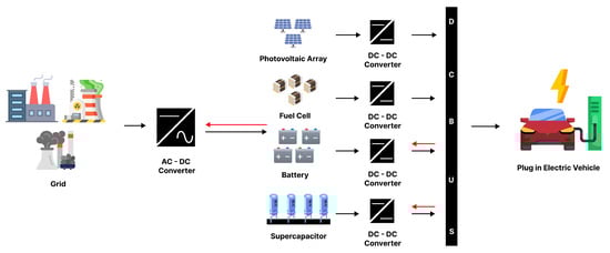
Figure 1.
Block diagram of the system.
2.1. Modeling of a PV Unit
The single-diode model is the most widely used representation for modeling a PV array, with its equivalent circuit shown in Figure 1. This model consists of a photocurrent source () in parallel with a single diode (D) [34]. Additionally, it incorporates a parallel resistance (), representing leakage current, and a series resistance (), which accounts for the internal resistance to current flow.
where represents the shunt leakage current, is the current flowing through the diode (A), and denotes the light-generated current (A). is the diode saturation current (A), q is the charge of an electron ( ), and is Boltzmann’s constant ( J/K). is the ideality factor of the diode, which typically depends on temperature (e.g., for 28 °C ). T is the temperature of the PV cell in Kelvin, is the PV cell output current (A), and is the PV cell output voltage (V). PV system is connected to DC bus via boost converter that is shown in the Figure 2. The mathematical model of the system obtained by using the volt second balance and capacitor charge balance that was shown in the Equations (24) and (25).
where represents the current generated by the PV unit, while denotes the PV voltage. is the inductance of the PV unit, and represents its series resistance. corresponds to the DC link voltage, is the duty cycle of the DC–DC converter, and represents the DC link capacitance. Lastly, I denotes the load current.
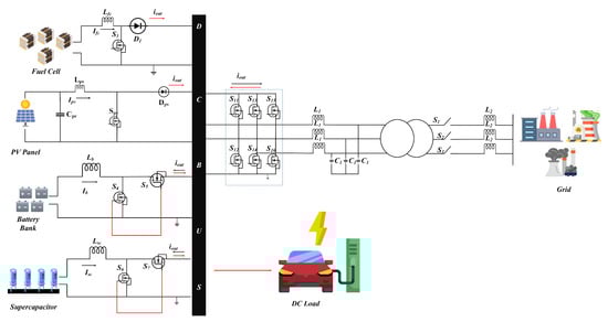
Figure 2.
Circuit diagram of the system.
2.2. Maximum Power Point Tracking (MPPT) Control of a PV Unit
The PV unit utilizes an MPPT technique to consistently deliver the maximum available power to the load, even under varying temperature and irradiance conditions. Due to the inherently low conversion efficiency of PV panels, an effective MPPT technique is critical for optimizing the performance of the solar PV system. In this work, an artificial neural network (ANN) is implemented to dynamically adjust the PV reference current in response to environmental fluctuations, thereby maximizing power extraction. The ANN is trained using MATLAB (version 2023a) with the Levenberg–Marquardt algorithm to ensure efficient and accurate optimization [35].
The regression plot in Figure 3 illustrates the high accuracy of the ANN in learning and predicting the optimal PV reference voltage under diverse solar conditions. The strong correlation evident in the plot confirms the network’s ability to capture complex nonlinear patterns, thereby enabling precise and consistent optimization of power extraction in the PV system.
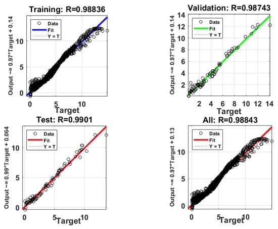
Figure 3.
Regression plot.
2.3. Fuel Cell
An FC is an electrochemical device that converts chemical energy from fuel, such as hydrogen, into electrical energy through a reaction with oxygen. Unlike traditional power generation methods, fuel cells operate with high efficiency and produce minimal greenhouse gas emissions, with water being the primary byproduct. FCs are highly scalable and can be used as a reliable backup power source or integrated into HRES to complement other energy sources. Their ability to provide stable power output makes them ideal for applications requiring consistent energy, especially during periods when intermittent renewable sources, such as solar or wind, are unavailable.
2.4. Supercapacitor
Electric double-layer capacitors, commonly referred to as supercapacitors [36], are widely employed in modern power grids due to their capability to accommodate rapid energy fluctuations. They are particularly valuable for meeting peak power demands, stabilizing grid voltage, and storing excess energy from renewable sources. Owing to their fast charge–discharge capability, supercapacitors are well suited for frequency regulation and short-term energy balancing. Although they provide higher power density compared to conventional batteries, they are typically integrated with battery systems in grid applications to combine the strengths of both technologies and achieve more efficient energy management.
2.5. Battery System
The battery system is interfaced with the DC bus through a bidirectional power converter, which can operate in either buck or boost mode depending on the direction of energy transfer. In buck mode, the converter enables efficient charging of the battery from the grid or other energy sources, while in boost mode it supports controlled discharge to deliver power back to the grid during periods of high demand or system instability. As a central component of grid energy storage, batteries provide backup power, stabilize voltage, and facilitate energy arbitrage. They further contribute to frequency regulation, absorb surplus energy from renewable generation, and ensure a reliable supply for critical loads. The battery capacitance is represented by .
2.6. Dynamic Modeling of Voltage Source Inverter
The instantaneous real (P) and reactive (Q) power at the point of common coupling (PCC) bus are considered as unmodelled dynamic parameters [16]. In the VSI system under study, an -to- transformation is applied to simplify the equations, thereby reducing computational effort and eliminating the need for additional phase-locked loop (PLL) calculations in parameter estimation. This transformation streamlines the overall modeling process. The state-space formulation of a VSI equipped with an LCL filter is presented in [16], and a dynamic model expressed in terms of P and Q is derived for further analysis. Accordingly, the VSI dynamic equations in the reference frame can be written as
Here, represents the VSI output voltage, is the voltage across the capacitor in the LCL filter, and and are the VSI and bus currents, respectively. , , and correspond to the resistance, inductance, and capacitance of the system.
The instantaneous real and reactive powers in the reference frame at bus 1 and bus 2 are given as
To reduce complexity, the -to- transformation is applied. The current dynamics in the reference frame are expressed as
Here, is the angular frequency of the system, and are the -transformed voltages.
The real and reactive power at bus 1 in the frame is calculated as
The dynamic equations for real and reactive power in the frame are
Finally, the control parameters and can be defined as
These equations establish a comprehensive dynamic model of the VSI in both the and reference frames, offering reduced computational complexity while clearly distinguishing the dynamics of real and reactive power.
2.7. Global Mathematical Modeling of the System
The proposed system integrates multiple energy sources and storage devices through a VSI, enabling efficient power conversion and distribution. Photovoltaic (PV) and fuel cell (FC) units are interfaced via boost converters to raise their voltage levels, while batteries and supercapacitors are connected through bidirectional buck–boost converters to regulate energy flow in both charging and discharging modes. The VSI performs the DC–AC conversion to supply various loads, including electric vehicles. A hierarchical power management structure is adopted, applying the principles of volt–second balance and capacitor charge balance to maintain stability and ensure optimal system performance. The corresponding state equations of the system are expressed as
3. Controller Design
To improve the performance and stability of the proposed system, nonlinear controllers are employed, utilizing advanced control strategies designed for dynamic energy environments. These controllers ensure accurate regulation of voltage and current, enhance power-sharing among distributed energy resources, and offer strong resilience against disturbances. By accounting for system nonlinearities and uncertainties, they enable seamless operation under varying load conditions and fault scenarios. Consequently, the system achieves higher energy efficiency, greater reliability, and overall optimal performance [37].
Conditional Based Integral Terminal Super-Twisting Sliding Mode Control
The condition-based integral terminal super-twisting sliding mode control represents an advanced strategy aimed at improving the performance and robustness of dynamic systems, particularly under uncertainties and external disturbances. By integrating the principles of sliding mode control (SMC), the integral terminal method, and the super-twisting algorithm [38], this approach guarantees finite-time convergence to the desired state while mitigating chattering effects.
The “condition-based” feature introduces adaptive mechanisms or predefined switching rules to dynamically adjust the control law, ensuring both precision and efficiency. This makes the method well suited for complex nonlinear systems where stability, accuracy, and effective disturbance rejection are essential [39]. The associated error terms are defined in Equation (22).
By taking the time derivative of Equation (22), the resulting expressions are obtained.
By substituting the values from the state Equations (15)–(20), the following results are derived
The sliding surface is given as
The sliding surfaces are defined using equations that incorporate the design parameters and , where , and all parameters are positive. By evaluating the time derivative of the sliding surfaces in Equation (30), the following results are obtained
By replacing the respective values of from Equations (24)–(29) into Equation (31), the following expressions are obtained
The Lyapunov candidate function proposed for the stability analysis is given as follows
By evaluating the time derivative of Equation (38), the following expression is obtained
By substituting the values of from Equations (32)–(37) into Equation (39), the following expressions are obtained
To ensure system stability, the derivative of the Lyapunov function, , must be negative definite. To satisfy the condition , the following constraint is imposed
The switching function, which is crucial for ensuring reachability and maintaining state trajectories on a designated surface, is represented by the left-hand side of Equations (41)–(43). Key components of this framework include the positive design parameters and the positive constants . Additionally, Equation (47) is utilized to compute the terms .
The range of the saturation function, represented by the variables , is limited to the constant values , where Q is a positive quantity determined by the design parameters . The mathematical expression for is given as follows
By substituting the constraints from Equations (40)–(48) into Equation (39), the following expressions are derived.
These equations confirm that the proposed controller guarantees system stability by ensuring that is negative definite. By solving Equations (41)–(46), the following results are obtained.
The control signals generated by the proposed method progressively stabilize the system, effectively eliminating the wind-up effect often encountered in traditional super-twisting algorithm-based controllers.
4. Improved Gray Wolf Optimization
Gray wolf optimization (GWO) is a population-based metaheuristic inspired by the hunting behavior of gray wolves [31]. To enhance its exploration and exploitation capabilities, an improved variant referred to as improved gray wolf optimization (I-GWO) was proposed in [40]. This variant incorporates a chaos factor to avoid premature convergence and escape local optima. In addition, a dynamic search mechanism adjusts the exploration process according to the iteration count and the characteristics of the fitness landscape.
In this study, I-GWO is employed to optimize the controller gains by minimizing an error-based cost function. The algorithm uses four types of search agents corresponding to the hierarchical roles in a wolf pack: alpha, beta, delta, and omega. These agents represent candidate solutions whose positions are iteratively updated based on a cost evaluation. The cost function is formulated as
Here, denotes the cost function, is the sliding surface, t represents time, and . The alpha wolf identifies the most promising solution, while beta and delta wolves follow the second- and third-best paths. The omega wolf explores alternative regions to maintain diversity in the search space. The process continues until a stopping criterion is satisfied, such as reaching the maximum number of iterations or achieving a target cost value. The best solution is given by the position of the agent with the lowest cost.
Figure 4 illustrates the performance of the I-GWO algorithm, showing the variation in cost values under different gain settings and confirming its efficiency in minimizing the error.
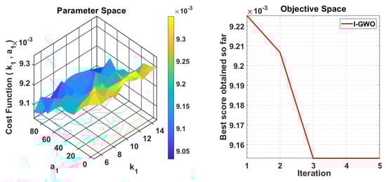
Figure 4.
CBITSTSMC.
The gain parameters of the proposed CBITSTSMC controller were optimized using the I-GWO algorithm. Wider search bounds were adopted for each parameter to ensure comprehensive exploration of the solution space, enabling the identification of robust, high-performing gain values under a variety of operating conditions.
The updated bounds for the gain search are as follows:
- (sliding mode convergence gain)
- (integral exponent)
- (integral scaling factor)
- (saturation dynamics gain)
- (super-twisting exponent)
The I-GWO algorithm was executed with the following stopping criteria:
- Maximum number of iterations: 100
- Cost function convergence threshold:
These settings strike a balance between exploration and convergence, enabling the optimizer to avoid local minima while ensuring stable and smooth controller response. The steps of the improved gray wolf optimization (I-GWO) algorithm for gain tuning are described in Algorithm 1.
| Algorithm 1: Improved gray wolf optimization (I-GWO) algorithm for gain tuning. |
 |
Reference Signal Generation and Parameter Optimization
The reference signals for each energy unit—namely the PV, FC, battery, and supercapacitor (SC)—are generated through an embedded energy management strategy (EMS). The EMS dynamically allocates power by considering source priority, state of charge (SOC), and the prevailing load demand. Specifically,
- The PV unit tracks a reference derived from maximum power point tracking (MPPT) output.
- The battery and SC references are generated to respond to transient load demands and SOC-based thresholds.
- The FC reference activates when the battery SOC falls below a predefined threshold, enabling recharge support.
All controller parameters including gain values (, ) and sliding surface coefficients (, , ) are optimized using the IGWO algorithm. The IGWO framework minimizes the objective function:
where is the sliding surface defined for the subsystem and is the tracking error. The parameters are constrained within stability-preserving bounds:
This optimization ensures robust convergence, reduced chattering, and improved control precision across all source converters under fluctuating load and intermittent renewable generation.
5. Simulation and Results
The simulation results highlight the effectiveness of the proposed energy management system under varying operating conditions. The solar irradiance profile in Figure 5a demonstrates step-wise variations, simulating realistic environmental scenarios. The corresponding PV current response in Figure 5b illustrates the system’s ability to track irradiance changes efficiently, ensuring optimal energy generation. The battery current dynamics in Figure 5c emphasize its dual role in energy storage battery system and delivery, with negative values indicating charging and positive values representing discharging to meet demand. Figure 5d depicts the fuel cell current, which supplements energy during high demand or low solar availability. Smooth transitions between states validate the robustness of the control strategies.
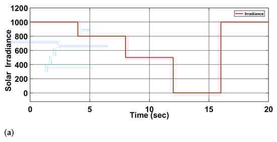
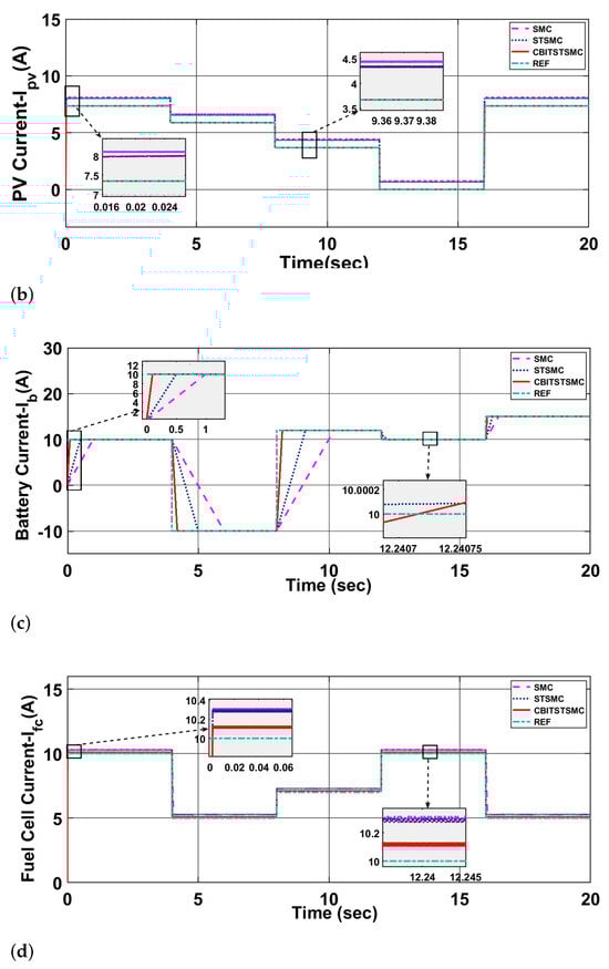
Figure 5.
(a) Solar irradiance, (b) PV current, (c) Battery current, (d) Fuel cell current.
Figure 6a showcases the supercapacitor’s rapid response to transient power fluctuations, stabilizing the system. Grid interactions are detailed in Figure 6b–d, where active and reactive current profiles highlight the grid’s ability to balance power, support reactive power compensation, and enable bidirectional energy flow for efficient management and stability. Moreover, these signals effectively manage various external disturbances, as demonstrated in Figure 7a, ensuring the system’s robustness and adaptability. While Figure 7b shows the DC bus voltage. Component specifications used in the simulation are summarized in Table 1, Table 2, Table 3, Table 4 and Table 5. Table 1 lists the AC microgrid ratings, including voltage, frequency, and inverter capacity. Table 2 details PV unit parameters such as module configuration and electrical properties, which determine energy generation efficiency. Table 3 outlines lithium-ion battery specifications, including voltage, capacity, and state-of-charge, ensuring reliable energy storage. Table 4 provides supercapacitor and fuel cell parameters, critical for transient load handling and backup energy supply. Table 5 presents converter specifications, ensuring power conversion efficiency and stability. The key variables and parameters for each subsystem are summarized in Table 6. Table 7 summarizes the optimal gain values together with their associated cost values.
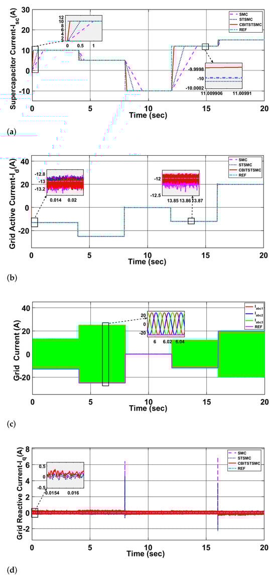
Figure 6.
(a) Supercapacitor Current, (b) Grid Active Current, (c) Grid Current, (d) Grid Reactive Current.
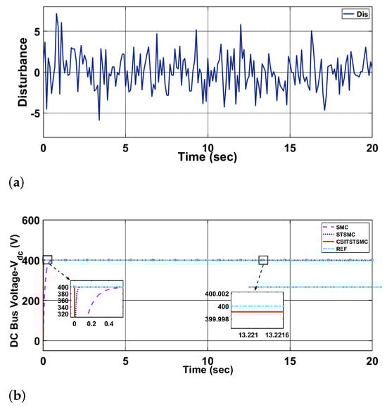
Figure 7.
(a) Disturbance, (b) DC bus voltage.

Table 1.
AC microgrid parameter ratings.
Table 2.
Specification of PV module parameters.
Table 3.
Key parameters of lithium-ion battery model.
Table 4.
Super capacitor and fuel cell parameters.
Table 5.
Converter specifications.
Table 6.
Comparison of variables and parameters across all subsystems.
Table 7.
Controller Gains.
The energy management strategy optimizes system performance by integrating components seamlessly. The PV system serves as the primary energy source, supported by the battery for medium- to long-term storage, and the supercapacitor for transient stabilization. The fuel cell provides reliable backup during low solar output or peak demand, while grid integration ensures dynamic energy exchange for uninterrupted supply. Advanced control algorithms, such as SMC, enable smooth transitions and efficient coordination, as demonstrated by the simulation results. The notation and parameters employed in the system modeling and controller design are consistently defined and summarized in Table 8.
Table 8.
System parameters.
The error performance metrics and transient response characteristics of the systems have been comprehensively evaluated, as summarized in Table 9 and Table 10. The CBITSTSMC controller consistently outperforms the SMC and STSMC controllers in precision, error minimization, and transient response. For error metrics, CBITSTSMC achieves significantly lower values. In the PV system, the MAPE is 1.8544 for CBITSTSMC, compared to 3115.0000 for SMC and 2699.8000 for STSMC. Similarly, the RMSE is 0.0037 for CBITSTSMC, markedly lower than 0.7593 for SMC and 0.6577 for STSMC. For the fuel cell system, the ITAE is 23.5240 for CBITSTSMC, substantially better than 59.0851 for SMC and 57.5607 for STSMC, showcasing superior error control.
Table 9.
Comparative analysis of transient response characteristics for active and reactive grid currents.
Table 10.
Evaluation of error performance metrics for all systems.
In terms of transient response (Table 11), the CBITSTSMC controller demonstrates faster and more stable dynamics. For the PV system, the rise time is reduced to 0.5000 s for CBITSTSMC, compared to 1.0000 for SMC and 0.8000 for STSMC. The settling time is also improved, with CBITSTSMC achieving 7.8000 s compared to 8.7500 for SMC and 8.2500 for STSMC. In the fuel cell system, the overshoot is minimized to 92.5000 for CBITSTSMC, compared to 98.0000 for SMC and 97.5000 for STSMC.
Table 11.
Comparative analysis of transient response characteristics for all systems.
Grid performance metrics (Table 9 and Table 12) further validate CBITSTSMC’s effectiveness. For active grid current, the RMSE is 0.0123 for CBITSTSMC, significantly lower than 0.0844 for SMC and 0.0081 for STSMC (Table 12). Additionally, the ITAE for DC link voltage is reduced to 0.1842 for CBITSTSMC, outperforming 3.9990 for SMC and 266.5067 for STSMC. Transient response analysis (Table 9) highlights that CBITSTSMC achieves the shortest rise time of 2.5000 s for active power control, compared to 3.0000 for SMC and 2.8000 for STSMC. The overshoot for DC link voltage is also minimized to 1.0005 for CBITSTSMC, compared to 2.0000 for SMC and 2.4990 for STSMC.
Table 12.
Evaluation of error performance metrics for active and reactive grid currents.
Experimental Configuration for Reproducibility
To ensure the reproducibility of all reported results, the following configuration details are provided for the experimental setup, data processing, and algorithm design:
- Environmental and Load Conditions: Solar irradiance and ambient temperature were varied within the realistic range of 15 °C to 45 °C. Transient faults and disturbances were applied during simulation windows of 5–8 s and 10–13 s to validate robustness under fluctuating conditions.
- Data Handling and Partitioning: For the ANN-based MPPT, the dataset was partitioned into 70% training, 15% validation, and 15% testing sets. Inputs include irradiance and temperature, while the output corresponds to the optimal PV reference current.
- Neural Network Architecture: A two-layer feedforward neural network with 10 and 8 neurons in the hidden layers was implemented. The network was trained using the Levenberg–Marquardt backpropagation algorithm for 500 epochs. Activation functions included tansig for hidden layers and purelin for the output. The learning rate was set to 0.01.
- Optimization Configuration (I-GWO): The improved gray wolf optimization algorithm employed a population size of 30 with a chaos factor of 0.9. The maximum number of iterations was fixed at 100, and the convergence threshold was . The objective cost function minimized was , derived from the sliding surface dynamics.
- Hardware-in-loop Platform: For real-time validation, controller-in-the-loop (CIL) tests were executed using the Texas Instruments Delfino C2000 F28379D microcontroller (Texas Instruments, Dallas, TX, USA). MATLAB R2023a/Simulink Embedded Coder (The MathWorks, Natick, MA, USA) was employed for real-time deployment.
These parameters collectively define the experimental environment and configuration required to reproduce the simulation results and controller behavior presented in this study.
6. Controller-in-the-Loop Evaluation
To overcome hardware and cost limitations, the proposed control strategies were validated through controller-in-the-loop simulations. This approach provides a cost-effective means of replicating controller behavior under real-time conditions, enabling a thorough assessment of system performance. Within the CIL framework, the system model in Simulink is discretized by replacing continuous blocks with their discrete counterparts. The corresponding code is then generated using the MATLAB compiler and deployed to a microcontroller, with parameter adjustments made to match the device specifications.
The CIL setup is shown in Figure 8, where the Delfino C2000 F28397D launchpad, equipped with a dual-core TMS320F28397D processor, is integrated with MATLAB/Simulink for real-time execution. Simulation results, presented in Figure 9, confirm accurate tracking of reference signals across all energy units. Specifically, the outcomes include the supercapacitor current (Figure 9a), grid active current (Figure 9b), battery current (Figure 9c), PV current (Figure 9d), and fuel cell current (Figure 9e). These results verify the robustness of the proposed controller under dynamic conditions.
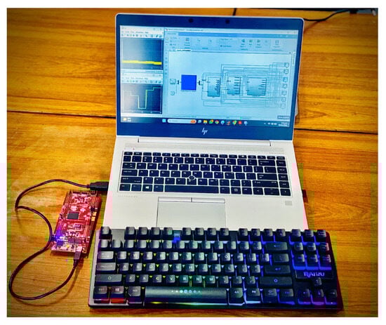
Figure 8.
Hardware setup.
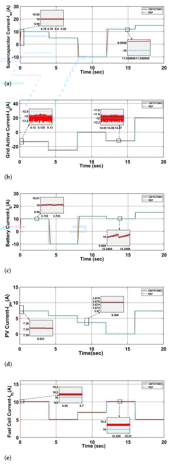
Figure 9.
(a) CIL result of supercapacitor current, (b) CIL result of grid active current, (c) CIL result of battery current, (d) CIL result of PV current, (e) CIL result of fuel cell current.
Moreover, the CIL experiments demonstrate the controller’s successful operation on actual hardware, validating its practical feasibility. The findings highlight the controller’s efficiency and reliability in reference tracking and effective power management across different energy sources and storage units.
7. Conclusions
This work presented a hybrid energy system coordinated by a condition-based integral terminal super-twisting sliding mode controller (CBITSTSMC). The controller was tuned using an improved gray wolf optimization (I-GWO) algorithm, ensuring superior transient and steady-state performance. Validation through both simulation and controller-in-the-loop testing confirmed the effectiveness of the approach, with results showing lower error metrics (MAPE, RMSE, ITAE), faster dynamic response, and improved robustness under variable operating conditions. The modular structure of the controller, combined with optimal resource allocation, enabled stable power flow, efficient energy sharing, and resilience during load variations and irradiance fluctuations. While the proposed system has shown strong performance, challenges may arise when extending the framework to larger microgrids or broader smart grid networks. Increasing the number of distributed units introduces additional issues such as communication overhead, synchronization, and multi-node coordination. The modular architecture of CBITSTSMC, however, makes it adaptable to decentralized and multi-agent control schemes, offering scalability for advanced smart grid applications. Likewise, the I-GWO tuning framework can be expanded to multi-objective optimization, providing more efficient control in complex and large-scale systems. Another important consideration is system resilience under extreme weather events or severe fault conditions. The proposed controller demonstrated strong disturbance rejection in both simulations and CIL tests, maintaining reliable operation under variable irradiance, dynamic load changes, and transient disturbances. These results suggest that the CBITSTSMC is capable of ensuring fast convergence and stable performance even under challenging conditions, making it a viable option for deployment in future smart grids. Future research will focus on incorporating reinforcement learning (RL) approaches—such as deep Q-networks (DQN), proximal policy optimization (PPO), and improved deep deterministic policy gradient (DDPG)—to achieve adaptive and predictive energy management under uncertainty. These techniques, which have shown encouraging results in recent studies, could enhance the autonomy and resilience of hybrid renewable energy systems in highly dynamic environments. Furthermore, statistical validation will be included by conducting multiple randomized simulation runs, reporting confidence intervals for key performance indicators, and applying significance tests (e.g., t-tests or ANOVA) to evaluate robustness and repeatability.
Author Contributions
Conceptualization, A.R. and R.G.; methodology, A.R.; software, R.G.; validation, R.G., H.I.S., and A.R.; formal analysis, R.G.; investigation, R.G.; resources, A.R.; data curation, R.G.; writing—original draft preparation, R.G.; writing—review and editing, A.R. and H.I.S.; visualization, R.G.; supervision, A.R.; project administration, A.R.; funding acquisition, A.R. All authors have read and agreed to the published version of the manuscript.
Funding
This research received no external funding.
Data Availability Statement
The original contributions presented in the study are included in the article, further inquiries can be directed to the corresponding author.
Acknowledgments
The authors gratefully acknowledge the Deanship of Graduate Studies and Scientific Research at Qassim University (QU-APC-2025).
Conflicts of Interest
The authors declare no conflict of interest. The sponsors had no role in the design, execution, interpretation, or writing of the study.
References
- Gul, B.T.; Ahmad, I.; Rehman, H.; Hasan, A. Adaptive neuro-fuzzy inference system and barrier function based nonlinear control of three phase grid-connected fast charging station for bidirectional power flow. J. Energy Storage 2025, 109, 114998. [Google Scholar] [CrossRef]
- Gul, B.T.; Ahmed, S.H.; Ahmad, I.; Zeb, O. Optimized barrier-condition nonlinear control of wireless charger-based hybrid electric vehicle. J. Energy Storage 2024, 97, 112705. [Google Scholar] [CrossRef]
- Nasim, U.; Bhatti, A.R.; Farhan, M.; Zeb, O.; Butt, A.D.; Paracha, K.N. An improved barrier function double integral sliding mode control of SynRM for hybrid energy storage system-based electric vehicle. J. Energy Storage 2024, 104, 114401. [Google Scholar] [CrossRef]
- Belrzaeg, M.; Sif, M.; Almabsout, E.; Benisheikh, U.A. Distributed generation for Microgrid technology. Int. J. Sci. Res. Updat. 2023, 6, 83–92. [Google Scholar] [CrossRef]
- Attah, R.U.; Garba, B.M.P.; Gil-Ozoudeh, I.; Iwuanyanwu, O. Strategic Partnerships for Urban Sustainability: Developing a Conceptual Framework for Integrating Technology in Community-Focused Initiatives. Master’s Thesis, University of Nottingham, Nottingham, UK, 2024. [Google Scholar]
- Khalid, M. Smart grids and renewable energy systems: Perspectives and grid integration challenges. Energy Strategy Rev. 2024, 51, 101299. [Google Scholar] [CrossRef]
- Souza, M.E.T.; Freitas, L.C.G. Grid-connected and seamless transition modes for microgrids: An overview of control methods, operation elements, and general requirements. IEEE Access 2022, 10, 97802–97834. [Google Scholar] [CrossRef]
- Rizvi, S.M. Active and Reactive Power-Sharing Method for Micro Grids with Multiple Grid Connections. Ph.D. Thesis, Curtin University, Bentley, WA, USA, 2024. [Google Scholar]
- Rathod, A.A.; Subramanian, B. Scrutiny of hybrid renewable energy systems for control, power management, optimization and sizing: Challenges and future possibilities. Sustainability 2022, 14, 16814. [Google Scholar] [CrossRef]
- Thirunavukkarasu, M.; Sawle, Y.; Lala, H. A comprehensive review on optimization of hybrid renewable energy systems using various optimization techniques. Renew. Sustain. Energy Rev. 2023, 176, 113192. [Google Scholar] [CrossRef]
- Li, Z.; Zhou, J.; Wen, J.; Chen, X. Dynamic modeling and operations of a heat-power station system based on renewable energy. Csee J. Power Energy Syst. 2021, 8, 1110–1121. [Google Scholar]
- Zhang, M.; Wu, Q.; Wen, J.; Lin, Z.; Fang, F.; Chen, Q. Optimal operation of integrated electricity and heat system: A review of modeling and solution methods. Renew. Sustain. Energy Rev. 2021, 135, 110098. [Google Scholar] [CrossRef]
- Naidu, R.K.; Palavalasa, M.; Chatterjee, S. Integration of hybrid controller for power quality improvement in photo-voltaic/wind/battery sources. J. Clean. Prod. 2022, 330, 129914. [Google Scholar] [CrossRef]
- Gross, A.M.; Malamaki, K.N.; Barragán-Villarejo, M.; Kryonidis, G.C.; Matas-Díaz, F.J.; Gkavanoudis, S.I.; Mauricio, J.M.; Maza-Ortega, J.M.; Demoulias, C.S. Energy management in converter-interfaced renewable energy sources through ultracapacitors for provision of ancillary services. Sustain. Energy Grids Netw. 2022, 32, 100911. [Google Scholar] [CrossRef]
- Sahri, Y.; Belkhier, Y.; Tamalouzt, S.; Ullah, N.; Shaw, R.N.; Chowdhury, M.S.; Techato, K. Energy management system for hybrid PV/wind/battery/fuel cell in microgrid-based hydrogen and economical hybrid battery/super capacitor energy storage. Energies 2021, 14, 5722. [Google Scholar] [CrossRef]
- Sedaghati, R.; Shakarami, M.R. A novel control strategy and power management of hybrid PV/FC/SC/battery renewable power system-based grid-connected microgrid. Sustain. Cities Soc. 2019, 44, 830–843. [Google Scholar] [CrossRef]
- Long, Y.; Wang, Y.M.; Yao, C.; Song, E.Z.; Dong, Q. Adaptive Second-order Sliding Mode Control of Electrical Throttles Based on Online Zero-crossing Checking. Int. J. Control. Autom. Syst. 2024, 22, 489–502. [Google Scholar] [CrossRef]
- Sonar, D. Renewable energy based trigeneration systems—Technologies, challenges and opportunities. In Renewable-Energy-Driven Future; Elsevier: Amsterdam, The Netherlands, 2021; pp. 125–168. [Google Scholar]
- Wang, J.; Wu, J.; Shen, H.; Cao, J.; Rutkowski, L. A decentralized learning control scheme for constrained nonlinear interconnected systems based on dynamic event-triggered mechanism. IEEE Trans. Syst. Man. Cybern. Syst. 2023, 53, 4934–4943. [Google Scholar] [CrossRef]
- Yao, Y.; Ding, F.; Horowitz, K.; Jain, A. Coordinated inverter control to increase dynamic PV hosting capacity: A real-time optimal power flow approach. IEEE Syst. J. 2021, 16, 1933–1944. [Google Scholar] [CrossRef]
- Worku, M.Y.; Hassan, M.A.; Abido, M.A. Power management, voltage control and grid synchronization of microgrids in real time. Arab. J. Sci. Eng. 2021, 46, 1411–1429. [Google Scholar] [CrossRef]
- Maizana, D.; Putri, S.M. Appropriateness analysis of implementing a smart grid system in campus buildings using the fuzzy method. Int. J. Power Electron. Drive Syst. 2022, 13, 873. [Google Scholar] [CrossRef]
- Saleem, S.; Ahmad, I.; Ahmed, S.H.; Rehman, A. Artificial intelligence based robust nonlinear controllers optimized by improved gray wolf optimization algorithm for plug-in hybrid electric vehicles in grid to vehicle applications. J. Energy Storage 2024, 75, 109332. [Google Scholar] [CrossRef]
- Khosravi, N.; Baghbanzadeh, R.; Oubelaid, A.; Tostado-Véliz, M.; Bajaj, M.; Hekss, Z.; Echalih, S.; Belkhier, Y.; Abou Houran, M.; Aboras, K.M. A novel control approach to improve the stability of hybrid AC/DC microgrids. Appl. Energy 2023, 344, 121261. [Google Scholar] [CrossRef]
- Al-Wesabi, I.; Zhijian, F.; Hussein Farh, H.M.; A. Al-Shamma’a, A.; Dong, H.; M. Al-Shaalan, A.; Kandil, T. Maximum power extraction and DC-Bus voltage regulation in grid-connected PV/BES system using modified incremental inductance with a novel inverter control. Sci. Rep. 2022, 12, 19958. [Google Scholar] [CrossRef]
- Elmorshedy, M.F.; Subramaniam, U.; Mohamed Ali, J.S.; Almakhles, D. Energy management of hybrid DC microgrid with different levels of DC bus voltage for various load types. Energies 2023, 16, 5438. [Google Scholar] [CrossRef]
- Singh, N.; Kumar, M.K. Decentralized control strategies for resilient power systems using multi-agent systems. In Proceedings of the MATEC Web of Conferences, Hammamet, Tunisia, 20–22 December 2024; EDP Sciences: Paris, France, 2024; Volume 392, p. 01183. [Google Scholar]
- Blanch-Fortuna, A.; Zambrano-Prada, D.; López-Santos, O.; Aroudi, A.E.; Vázquez-Seisdedos, L.; Martinez-Salamero, L. Hierarchical Control of Power Distribution in the Hybrid Energy Storage System of an Ultrafast Charging Station for Electric Vehicles. Energies 2024, 17, 1393. [Google Scholar] [CrossRef]
- Wang, R.; Tian, X.; Wei, Z.; Sun, Q.; Wang, P. Fully distributed energy management strategy for DC bus energy distribution in multi-bus DC EV charging stations. Sci. Rep. 2025, 15, 1009. [Google Scholar] [CrossRef]
- Qayyum, N.; Khan, L.; Wahab, M.; Mumtaz, S.; Ali, N.; Khan, B.S. Fractional-Order Swarming Intelligence Heuristics for Nonlinear Sliding-Mode Control System Design in Fuel Cell Hybrid Electric Vehicles. World Electr. Veh. J. 2025, 16, 351. [Google Scholar] [CrossRef]
- Zheng, X. Robust Control for PV and Battery DC Microgrid System using Full-Order Terminal Sliding Mode and Passive-Based Control. IET Renew. Power Gener. 2025, 19, e70033. [Google Scholar] [CrossRef]
- Liu, M.; Li, Y.; Li, P.; Zhang, W.; Chen, Q. Degradation adaptive energy management strategy for FCHEV based on the Rule-DDPG method: Tailored to the current SOH of the powertrain. Appl. Energy 2023, 347, 121509. [Google Scholar] [CrossRef]
- Jia, C.; Liu, W.; He, H.; Chau, K. Superior energy management for fuel cell vehicles guided by improved DDPG algorithm: Integrating driving intention speed prediction and health-aware control. Appl. Energy 2025, 394, 126195. [Google Scholar] [CrossRef]
- Armghan, A.; Hassan, M.; Armghan, H.; Yang, M.; Alenezi, F.; Azeem, M.K.; Ali, N. Barrier function based adaptive sliding mode controller for a hybrid AC/DC microgrid involving multiple renewables. Appl. Sci. 2021, 11, 8672. [Google Scholar] [CrossRef]
- Kiran, S.R.; Basha, C.H.; Singh, V.P.; Dhanamjayulu, C.; Prusty, B.R.; Khan, B. Reduced simulative performance analysis of variable step size ANN based MPPT techniques for partially shaded solar PV systems. IEEE Access 2022, 10, 48875–48889. [Google Scholar] [CrossRef]
- Ghias, R.; Rehman, A.; Ahmad, I.; Saleem, S.; Shah, S.H.A. Optimized Nonlinear Control Strategies for Hybrid Electric Vehicles Integrating Photoelectrochemical and Photovoltaic Cells with Fuel Cells, Batteries, and Supercapacitors. In Proceedings of the 2024 3rd International Conference on Emerging Trends in Electrical, Control, and Telecommunication Engineering (ETECTE), Lahore, Pakistan, 26–27 November 2024; IEEE: New York, NY, USA; pp. 1–7. [Google Scholar]
- Rehman, A.; Ghias, R.; Ahmed, S.H.; Saleem, S.; Ahmad, I.; Sherazi, H.I. Enhancing antiviral therapies through nonlinear control of hepatitis c virus dynamics. Biomed. Signal Process. Control. 2024, 97, 106727. [Google Scholar] [CrossRef]
- Zar, A.; Rehman, H.; Ahmad, I. Neural network based optimized barrier conditioned double super-twisting sliding mode controller of electric vehicle charger with grid to vehicle and vehicle to grid modes. J. Energy Storage 2023, 74, 109234. [Google Scholar] [CrossRef]
- Ghias, R.; Hasan, A.; Ahmad, I. Artificial neural network based conditional controllers with saturated action for multi-renewable hybrid alternating or direct current microgrids in islanded and grid-connected modes. J. Energy Storage 2024, 94, 112139. [Google Scholar] [CrossRef]
- Ahmed, S.H.; Rehman, A.; Ahmad, I. A novel approach to nonlinear control in tuberculosis transmission dynamics. In Proceedings of the 2023 2nd International Conference on Emerging Trends in Electrical, Control, and Telecommunication Engineering (ETECTE), Lahore, Pakistan, 27–29 November 2023; IEEE: New York, NY, USA, 2023; pp. 1–8. [Google Scholar]
Disclaimer/Publisher’s Note: The statements, opinions and data contained in all publications are solely those of the individual author(s) and contributor(s) and not of MDPI and/or the editor(s). MDPI and/or the editor(s) disclaim responsibility for any injury to people or property resulting from any ideas, methods, instructions or products referred to in the content. |
© 2025 by the authors. Licensee MDPI, Basel, Switzerland. This article is an open access article distributed under the terms and conditions of the Creative Commons Attribution (CC BY) license (https://creativecommons.org/licenses/by/4.0/).