1. Introduction
The electrical power grid is a vast and intricate system responsible for transmitting electricity from producers to consumers, serving as a cornerstone of modern infrastructure and daily life. However, rising concerns over the environmental consequences of conventional power generation, particularly its role in greenhouse gas emissions and pollution, are accelerating the shift toward cleaner, more sustainable energy solutions [
1]. One of the most promising developments in this transition is the emergence of microgrids (MGs) powered by renewable energy sources (RESs). These systems offer an effective means of reducing environmental impact while supporting global efforts to combat climate change. RES-based microgrids are gaining popularity due to their high efficiency, ease of deployment, and significant role in expanding renewable energy adoption. By aligning distributed generation with local demand, microgrids enhance power reliability and enable efficient utilization of waste heat clear advantages over conventional centralized systems [
2]. Photovoltaics (PVs) have proved especially promising among other renewable technologies, and their efficiency enhancement rate is at 9.0% per annum [
3]. Future projection using the past highs could, therefore, not be reliable unless a keen insight regarding the causes of this rise is brought to the fore. In this respect, Ref. [
4] offers an extended analysis of smart grid development paying attention to the significant elements of it like its communication infrastructure, demand response systems, and cybersecurity. Other issues raised by the study are resource management, optimization, reliability, and creation of self healing capabilities, which are very vital in accomplishing the full potential of the smart grid.
Hybrid AC/DC microgrids (MGs), composed of distributed generators, energy storage systems, and varying load profiles, face considerable control and optimization challenges [
5]. The unpredictable nature of renewable energy generation and the continuous variations in DC load demand can significantly impact system stability and operational efficiency [
6]. Voltage fluctuations during transitions between islanded and grid-connected modes further complicate reliable operation. To address these challenges, effective power management strategies are essential for ensuring seamless performance under different generation and load conditions [
7,
8].
Several studies have proposed linear control techniques for microgrid stability, including integral terminal Sliding Mode Control applied on both the machine and grid sides [
9]. While effective under certain conditions, these models are typically optimized for islanded mode and often require dual control schemes, introducing additional complexity. Similarly, linear controllers such as traditional droop control are commonly used for DC bus regulation but struggle to respond effectively under highly variable operating conditions. Although robust
controllers have been developed to mitigate uncertainties caused by load variations [
10], comprehensive stability analysis in such frameworks remains limited. Furthermore, linear methods frequently fail to capture the nonlinear dynamics of RESs when integrated with power converters and energy storage systems, making them insufficient for complex real-world applications [
11].
In order to circumvent the limitations of linear controllers, researchers have increasingly adopted nonlinear control strategies. Among them, the Double Integral Sliding Mode Controller (DISMC) has been widely used in grid-connected wind–PV hybrid systems to enhance steady-state performance, voltage regulation, and robustness under varying operating conditions [
12]. However, classical SMC approaches still suffer from inherent issues such as chattering, sensitivity to parameter uncertainties, and limited robustness against external disturbances [
13]. More recent investigations have explored DISMC implementations within renewable energy DC microgrids equipped with hybrid energy storage systems, demonstrating improvements in voltage regulation, dynamic responsiveness, and system-wide stability validated via Lyapunov-based analysis and hardware-in-the-loop (HIL) testing [
14]. Nonetheless, challenges remain unaddressed, particularly regarding the intermittent nature of renewable energy sources (RESs), which often induces voltage oscillations when multiple sources are coordinated in hybrid AC/DC topologies [
15]. Adaptive droop control, though popular for its decentralized structure, may also degrade in performance due to communication delays when multiple energy storage systems (ESSs), PVs, and wind units are interconnected.
To overcome these challenges, recent developments in Sliding Mode Control (SMC) have focused on improving robustness, mitigating chattering, and ensuring fast convergence in microgrid environments under non-ideal operating conditions. Alipour et al. [
16] proposed an observer-based backstepping SMC for DC microgrids feeding constant power loads, ensuring system stability despite load perturbations. Mustafa [
17] developed an adaptive SMC technique tailored for buck converters interfaced with hybrid microgrids, exhibiting superior current regulation under varying conditions. Similarly, Alnami et al. [
18] designed an adaptive dynamic surface Sliding Mode Controller for PV-integrated systems, achieving enhanced tracking accuracy and resilience to external disturbances. Ma et al. [
19] introduced a fractional-order SMC that addresses time-delay and parametric uncertainties in distributed generation systems. In addition, Mahmoudi et al. [
20] integrated neural networks with SMC for maximum power point tracking (MPPT), enabling improved adaptability under changing irradiance. Chen et al. [
21] applied a double-integral SMC framework for fault-tolerant control in hybrid energy architectures. While these contributions represent significant advancements, many of them lack saturation-aware logic or have not been validated beyond simulation environments. Motivated by these limitations, the proposed CBSTSMC incorporates conditional feedback to handle actuator saturation, ensures chattering-free performance, and is verified via Controller-in-the-Loop (CIL) testing for real-time practical feasibility.
In order to overcome these multidimensional problems, this paper is proposing a CBSTSMC of hybrid AC/DC microgrids. The method is highly robust, chatter-free, and easy to implement. The CBSTSMC is specifically created to eliminate wind up created by conveying of control signals. In simple operating conditions without the effects of actuator saturation, the controller acts like a regular Super-Twisting Algorithm (STA), so the performance of the system is smooth and stable. Additionally, the controller incorporates saturation-aware feedback logic, allowing it to switch dynamically between nominal and nonlinear modes depending on operating conditions, which significantly improves stability under fast transients. To further enhance control accuracy and eliminate the need for manual tuning, the CBSTSMC gains are optimized using an Improved Grey Wolf Optimization (IGWO) algorithm, which ensures fast convergence, robustness to uncertainties, and superior steady-state error performance.
The proposed hybrid microgrid architecture is shown in
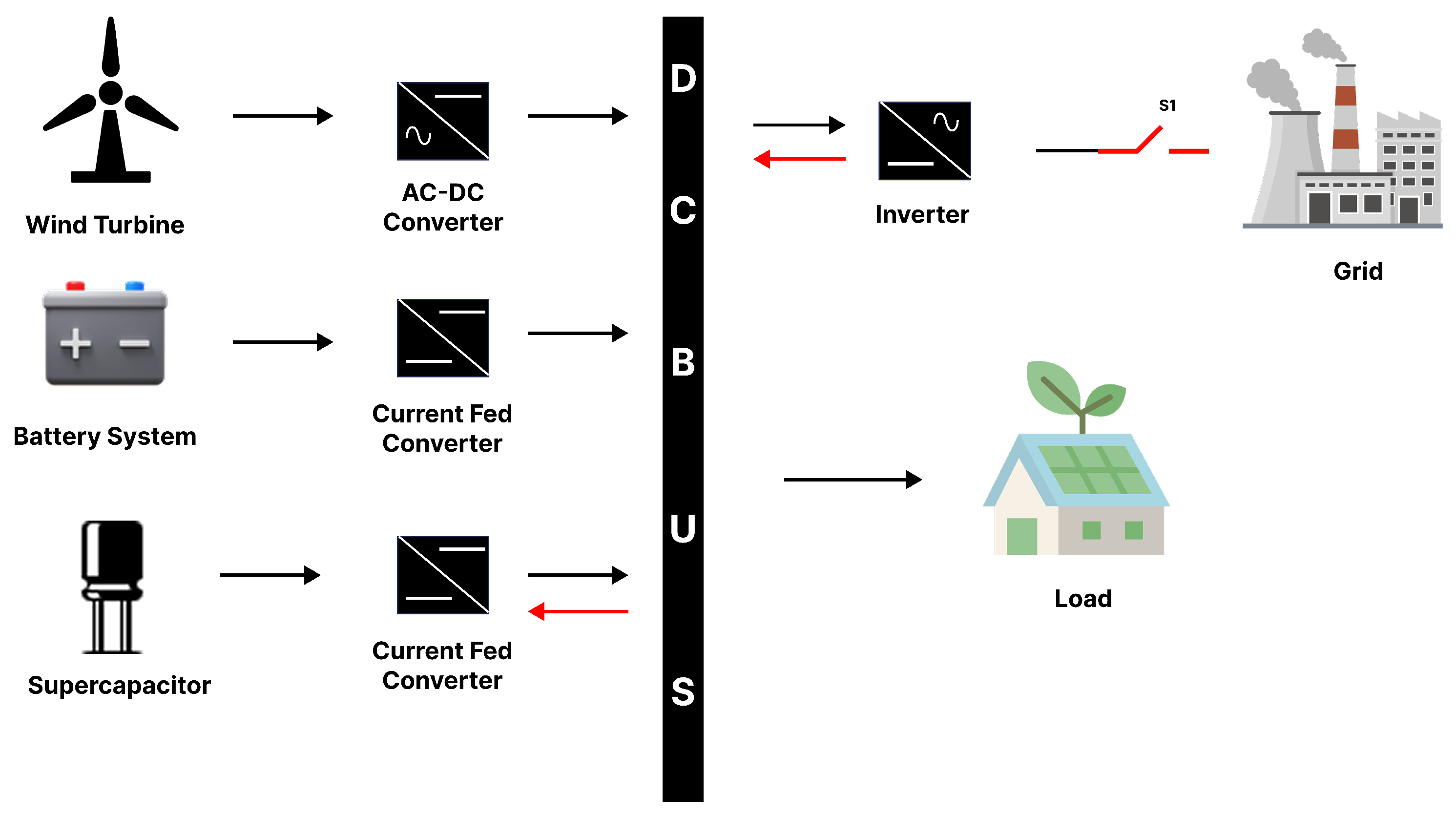
Figure 1 comprising wind energy, battery-and-supercapacitor-based energy storage, grid connection, and different loads. The subsystem within wind energy has a wind turbine and a Permanent Magnet Synchronous Generator (PMSG) connected to a bridge rectifier, DC–DC boost converter, and a DC-link bus, whereas the battery and supercapacitor as assembled in hybrid energy storage devices are linked to the DC bus via a current fed converter. Such an arrangement allows for arranging the efficient management of energy and stable work under a wide variety of conditions. This architecture is tested under both simulation and real-time Controller-in-the-Loop (CIL) environments, verifying its hardware compatibility and performance robustness under real-world disturbances.
The proposed research involves stable voltage regulation at AC and DC buses with variable loads, intermittent RESs, and external disturbances. This work has the following main contributions:
Development of multiple control strategies to ensure AC and DC bus stability under dynamic load variations, external disturbances, and RES fluctuations.
Design and implementation of the proposed CBSTSMC controller tailored for hybrid AC/DC microgrids.
Construction of a comprehensive global model to validate the proposed control strategy’s effectiveness through simulation and analysis.
Integration of an IGWO-optimized gain tuning layer to enhance dynamic tracking and minimize steady-state error across diverse scenarios.
Validation of the control scheme through real-time CIL testing on a Texas Instruments Delfino C2000 microcontroller, confirming its feasibility for embedded deployment.
This paper is structured as follows:
Section 2 presents the mathematical modeling of the system.
Section 3 focuses on the design of the controller and the optimization techniques utilized. The simulation results and their analysis are provided in
Section 4.
Section 5 discusses the Controller-in-the-Loop controller performance. Finally,
Section 6 concludes the paper with a summary of key findings.
2. Mathematical Modeling
In this section, the mathematical model of the system is discussed.
2.1. Modeling of Wind Energy System in DC Microgrids
Here, there is a wind system incorporated into a DC microgrid in which a wind turbine, a Permanent Magnet Synchronous Generator (PMSG), an uncontrolled diode rectifier (UDR), and a DC–DC booster are presented. The wind turbine will provide mechanical energy that has to be converted to AC by the PMSG and be rectified by the UDR and switched to DC and processed by the boost converter. The system also uses the Perturb and Observe Maximum Power Point Tracking (MPPT) method in order to optimize as much power as it can in different wind speeds [
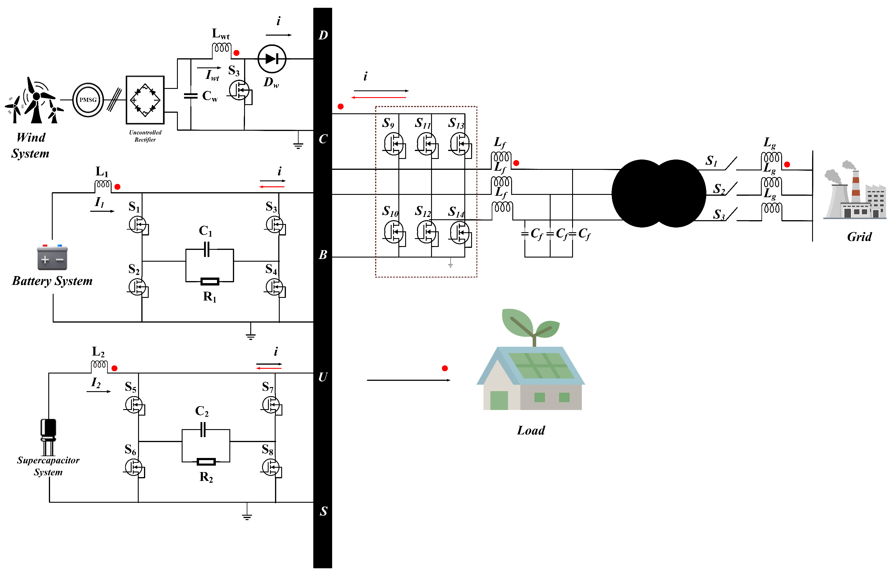
22]. The entire wind system, including the boost converter, can be seen in
Figure 2.
The power of the wind, which is available in the form of mechanical energy, is estimated as
The air density,
(kg/m
3), turbine radius,
R, and power coefficient,
, as well as wind speed, V, are the only parameters used by Equation (
1). The pitch of the blade, pitch angle,
, and power coefficient,
, affect the tip speed ratio, which varies between 0.4 and 0.45 but has a theoretical limit of 0.59. Wind turbine efficiency and efficient capture of energy are directly associated with the tip speed ratio as defined in Equation (
2):
In Equation (
2), we refer to the angular speed of the rotor in radians per second as
. The maximum mechanical power
, which is extracted out of the winds under optimal wind operating conditions, is written as
where
is air density, A is the turbine’s swept area, Cpmax is the maximum power coefficient, and lambdaopt is the optimal tip speed ratio in Equation (
3).
The power coefficient
is determined with this empirical formula:
where the intermediate variable
is given by
The tip speed ratio
, previously introduced in Equation (
6), is defined as
The power coefficient
, which governs the aerodynamic efficiency of the wind turbine, is modeled using an empirical expression as shown in Equation (
4). This nonlinear function captures the dependency of power extraction on the tip speed ratio
and pitch angle
. The model coefficients are selected as
These constants are widely used in wind energy simulation studies and are derived from the seminal work of Heier on wind turbine aerodynamics and integration systems [
23]. The same model structure and coefficient values are also adopted in industrial-grade simulation tools, including MATLAB/Simulink’s Wind Turbine blockset [
24]. This formulation allows accurate yet computationally efficient modeling of turbine performance under varying wind conditions and serves as a basis for implementing MPPT strategies.
The maximum power output is obtained using Equation (
1).
Figure 3 illustrates the implementation of the Perturb and Observe (P&O) MPPT algorithm in the wind subsystem. The Perturb and Observe (P&O) algorithm is adopted for MPPT due to its simplicity, low computational burden, and ability to effectively track the maximum power point without requiring prior knowledge of turbine characteristics. Although the P&O MPPT algorithm is well established in the literature [
25], its flowchart is included here to clearly illustrate the specific implementation adopted in the proposed system.
The DC–DC boost converter consists of an inductor,
, an input capacitor,
, a MOSFET switch,
, and a diode,
, which collectively regulate the energy flow from the wind energy system to the DC bus. The dynamic behavior of the proposed wind energy boost converter is modeled using the average-value method, applying the principles of volt-second balance (VSB) and capacitor charge balance (CCB). The resulting differential equations, shown in Equations (
7) and (
8), describe the converter’s performance and assist in analyzing its efficiency and control dynamics.
In these equations, is the output voltage across the DC-link capacitor, is the current from the wind energy subsystem, and represents the duty cycle control input for the boost converter. These equations reflect the real-time energy conversion process and are essential for implementing robust control strategies in the wind-driven DC microgrid.
2.2. Hybrid Storage System
In the proposed hybrid energy management scheme, batteries and supercapacitors are used in a complementary manner to enhance both power quality and storage lifespan. Supercapacitors are well suited for handling short-duration, high-power fluctuations due to their rapid charge–discharge capability and high cycle life. Conversely, batteries are effective for managing long-duration energy demands and ensuring steady power delivery over extended periods. By coordinating the operation of these two storage types, the system can respond quickly to transients using the supercapacitor while offloading energy balancing and slower dynamics to the battery. This synergy improves energy efficiency, reduces stress on battery cells and supports reliable microgrid operation under variable renewable inputs.
2.2.1. Supercapacitors
Supercapacitors, also referred to as Electric Double-Layer Capacitors (EDLCs) [
26], play a significant role in enhancing the performance and stability of modern grid systems. Their ability to rapidly charge and discharge makes them particularly effective for managing peak power demands, stabilizing voltage fluctuations, and supporting load leveling during transient conditions. In smart grids and microgrids, supercapacitors are often used to provide immediate power support during sudden load changes and to smooth out short-term power imbalances caused by renewable energy sources. They are also valuable in applications such as frequency regulation, voltage support, and bridging power during the switching of energy sources [
27]. Although supercapacitors have lower energy density compared to conventional batteries, their high power density and fast response time make them ideal for integration in hybrid energy storage systems, where they complement batteries to improve grid reliability and dynamic response.
2.2.2. Battery Systems
In grid systems, particularly in microgrids and hybrid AC/DC networks, battery energy storage systems (BESSs) are typically integrated through bidirectional power converters [
28]. These converters operate in either buck or boost mode based on the direction of power flow [
29]. In buck mode, the converter manages efficient charging of the battery from the grid or renewable sources, whereas in boost mode, it facilitates controlled battery discharge to support the load or grid [
9].
Batteries serve as a core component of energy storage infrastructure in modern grids. They help balance supply and demand, provide backup power, enable energy arbitrage, and enhance system reliability. Additionally, batteries support functions such as load shifting, frequency regulation, and voltage stabilization, especially when integrated with intermittent renewable energy sources. The battery’s capacitance is typically denoted as , and it plays a critical role in defining the storage system’s dynamic performance.
2.3. Dynamic Modeling of Energy Storage Components in a Current-Fed Configuration
In the proposed hybrid energy storage system, the battery and supercapacitor are interfaced via current-fed converters, making current the primary control variable. The evolution of voltage across the storage elements depends on the integrated current profile.
The energy stored in each element is given by
where
denotes the instantaneous energy (J),
C is the capacitance or effective capacity (F or Ah), and
is the terminal voltage.
For the supercapacitor, the voltage dynamics are governed by:
Similarly, for the battery in a simplified model,
where
and
are the injection/withdrawal currents, and
and
are the time-varying terminal voltages of the supercapacitor and battery, respectively.
This current-fed modeling approach aligns with the converter topology used in the proposed system and reflects the natural voltage build-up or depletion based on injected current, enabling precise control of power sharing and dynamic response.
2.4. Inverter
The system includes a three-phase inverter, as illustrated in
Figure 2, which is used to convert DC power to AC for interfacing with both the utility grid and local AC loads. While no explicit inverter equations are presented in this work, the inverter shown in the figure represents the configuration employed in the AC sub-grid. A phase-locked loop (PLL) module is typically used for synchronization, and an LCL filter on the AC side enhances power quality by attenuating high-frequency harmonics. The filter components are selected based on a defined cutoff frequency to ensure system stability by keeping lower-order harmonic frequencies below this threshold. For mathematical modeling of the AC subsystem, Park’s and Clarke’s
transformations are applied to simplify the analysis by converting three-phase AC signals into equivalent DC quantities in the rotating reference frame.
2.5. Modeling of the Grid System
The proposed model represents a comprehensive structure of the hybrid AC/DC microgrid system under study, as illustrated in
Figure 2. This model incorporates the key components of the system, including renewable energy sources, bidirectional converters, energy storage units, and various loads. To accurately capture the dynamic behavior of the system, an average state-space model is developed for the power converters used within the microgrid. These models are derived using the principles of volt-second balance and capacitor charge balance, taking into account the currents and voltages across different components. The resulting set of equations describes the interaction of converters and their role in regulating power flow across the AC and DC buses. This mathematical framework enables detailed analysis of the system’s performance and provides a foundation for implementing advanced control strategies. It also allows for performance optimization of the grid under a wide range of operating conditions, including load changes, renewable generation variability, and mode transitions between grid-connected and islanded operations.
The state variables and represent the inductor currents of the battery, supercapacitor, and wind energy converters, respectively, while denotes the DC bus voltage in the integrated DC microgrid system.
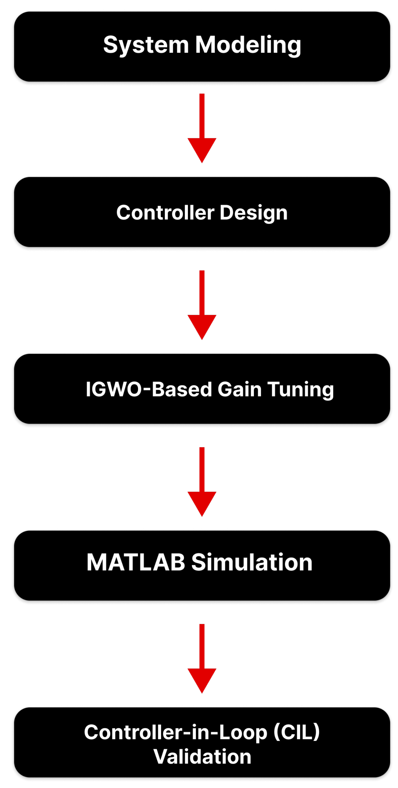
The novelty of this study lies in the integration of an IGWO-optimized Conditional-Based Super-Twisting Sliding Mode Controller (CBSTSMC) within a hybrid AC/DC microgrid. Unlike fixed-gain techniques, this approach ensures dynamic gain tuning in real time, allowing improved convergence, minimal chattering, and superior robustness under load variation and uncertainty. The complete methodological flow, shown in
Figure 4, outlines the structured steps from system modeling to controller deployment using real-time Controller-in-the-Loop (CIL) validation.
4. Simulation and Results
The proposed AC/DC hybrid microgrid system was simulated using MATLAB R2024b/Simulink to evaluate the performance of the CBSTSM in both islanded and grid-connected modes. The system incorporates wind energy, a battery unit, a supercapacitor bank, and a grid interface. Detailed parameters for each subsystem are provided in
Table 1,
Table 2,
Table 3 and
Table 4.
Table 1 outlines the key characteristics of the wind energy system, including air density, wind speed, and rotor specifications.
Table 2 presents the electrical and mechanical parameters of the Permanent Magnet Synchronous Generator (PMSG) used in the wind energy conversion system.
Table 3 lists the inverter-side specifications, such as DC-link voltage, filter components, and switching frequency.
Table 4 summarizes the passive circuit elements including inductors, capacitors, and resistors used throughout the battery, supercapacitor, and wind subsystems. To enhance clarity,
Table 5 summarizes the key symbols used in the system modeling and controller design sections. For great reproducibility, the gain parameters for the proposed CBSTSMC controller are explicitly presented in
Table 6. These gains were tuned using the Improved Grey Wolf Optimization (IGWO) with an ITAE-based cost function. The values correspond to the individual subsystems, wind energy, battery storage, and supercapacitor.
The primary objective of the control strategy is to maintain stable AC and DC bus voltages, thereby improving the overall stability and reliability of the microgrid.
Figure 6a illustrates external disturbances in the system and
Figure 6b shows the load profile of the system. The simulation results presented in
Figure 7,
Figure 8 and
Figure 9 correspond to the measurement points indicated by red dots in the system schematic shown in
Figure 2. These points include the DC link, inverter output, load terminal, and power converter branches. In the system architecture, the wind energy source is connected through an MPPT algorithm before interfacing with a boost converter. Battery and supercapacitor systems serve as energy storage components, helping regulate voltage and maintain power balance. During islanded mode, the energy management unit coordinates the use of stored energy from the battery and supercapacitor to meet load demands. In the grid-connected mode, the voltage source inverter (VSI) enables bidirectional power flow between the grid and the microgrid based on load requirements. The CBSTSMC controller dynamically generates control signals to ensure robust and stable operation under varying conditions. To validate the effectiveness of the proposed CBSTSMC, comprehensive simulations were conducted under both transient and steady-state operating conditions. Key current waveforms from the battery, grid, and active components were analyzed to assess the controller’s dynamic response, disturbance rejection, and tracking accuracy. In this project, an Energy Management System (EMS) is developed to control and optimize power flow in a hybrid energy setup comprising wind energy, battery storage, supercapacitors, and the electrical grid. The EMS operates based on a prioritized control strategy that activates power sources in a specific sequence, depending on their availability and sustainability. Wind power is given the highest priority due to its renewable nature. If sufficient wind energy is available, it directly supplies the load. If wind alone cannot fulfill the demand, the system checks the battery storage system. The battery discharges to meet the deficit and charges when there is surplus power. A positive current in the battery indicates discharging, while a negative current indicates charging.
If the battery cannot meet the remaining load, the supercapacitor is activated. It acts as a fast-response backup to handle short bursts of high power demand. Like the battery, the current direction indicates its state of charge or discharge. If all these sources fail to supply the required load, the system connects to the grid. The grid acts as the last resort. A positive grid power value means power is being drawn from the grid, while a negative value means excess power is being exported to it. This hierarchical strategy ensures optimal usage of renewable sources and minimizes grid dependency. Zero output from any source implies it is inactive due to unavailability, full charge, or low priority.
Figure 7 presents the wind current waveform
, where the proposed Conditional-Based Super-Twisting Sliding Mode Controller (CBSTSMC) exhibits highly accurate reference tracking. Across various load steps, CBSTSMC maintains smooth transitions and low oscillations, as clearly highlighted in the magnified views. In contrast, the conventional Sliding Mode Controller (SMC) shows greater fluctuations and slower settling, particularly during sudden disturbances. This demonstrates the superior dynamic performance and robustness of CBSTSMC in managing wind energy conversion.
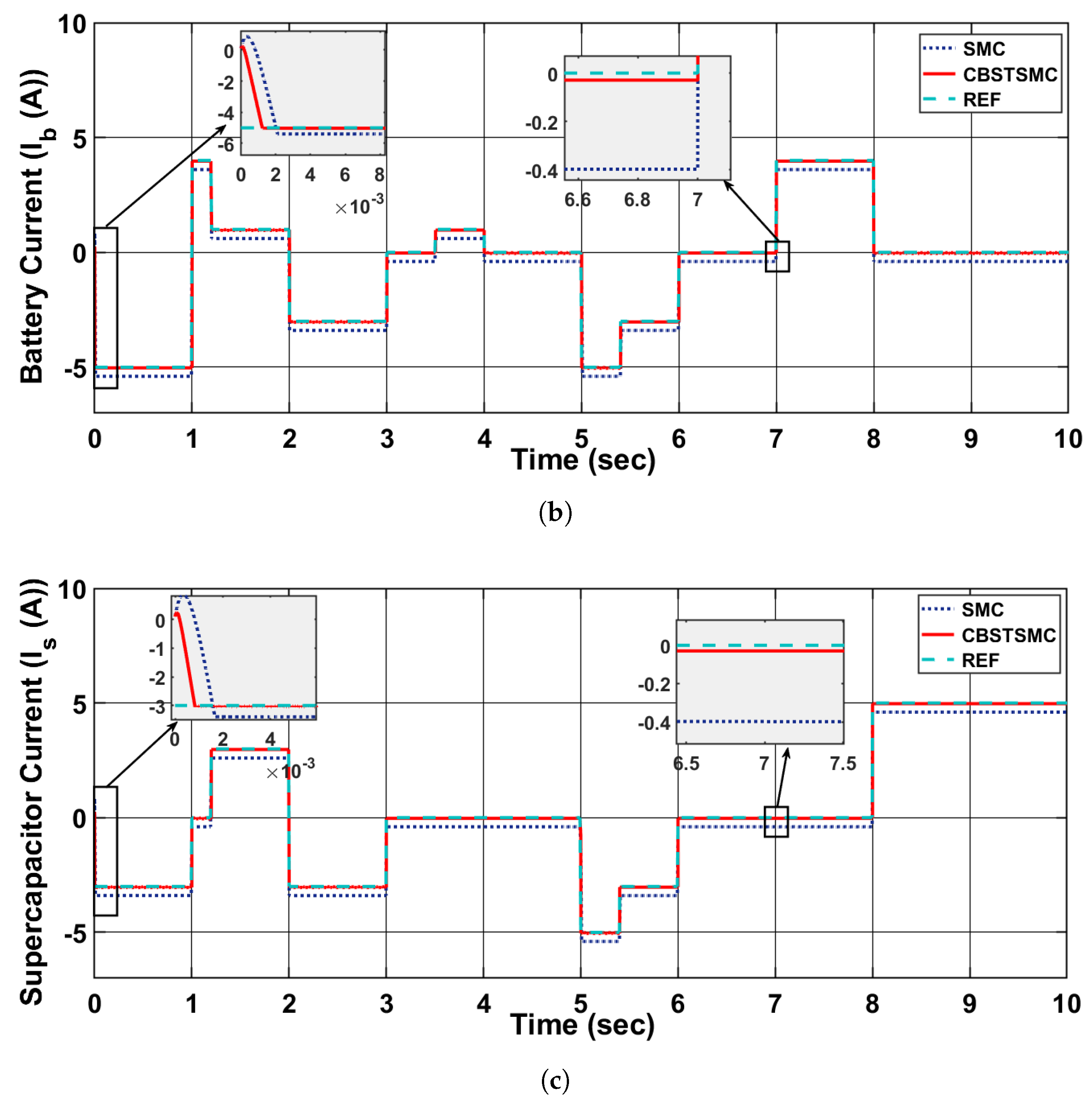
Figure 7b illustrates the battery current
, highlighting the system’s charging and discharging behavior. Negative current values indicate charging, while positive values represent discharging. The CBSTSMC closely tracks the reference signal with high accuracy and minimal overshoot, even during abrupt load changes. Compared to the traditional Sliding Mode Controller (SMC), the CBSTSMC significantly reduces chattering and enhances convergence speed. Zoomed-in sections emphasize the superior dynamic response and smoothness of CBSTSMC during switching events.
Figure 7c illustrates the supercapacitor current
, where both charging (negative current) and discharging (positive current) states are well managed. The CBSTSMC tracks the reference profile accurately, with rapid current reversal and minimal overshoot during mode transitions. As shown in the zoomed areas, CBSTSMC significantly reduces the chattering effect compared to SMC and maintains better stability during both transients and steady-state periods.
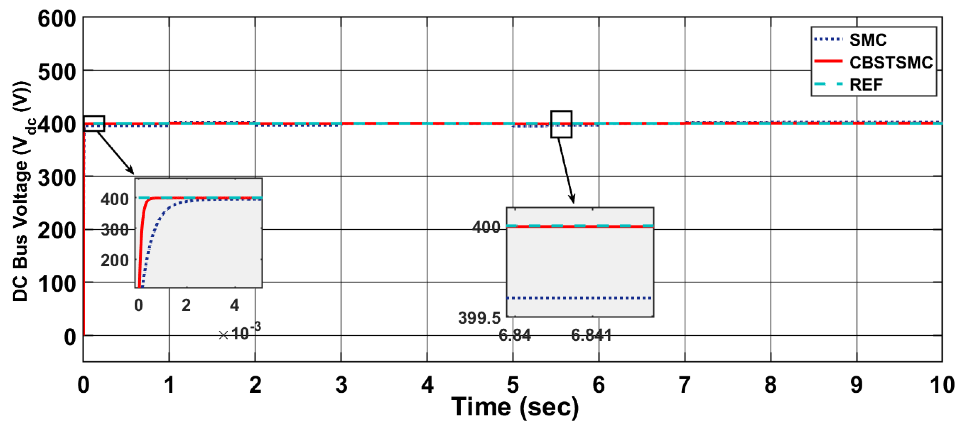
Figure 8 shows the DC bus voltage of the system. In
Figure 9, the three-phase grid current
demonstrates stable sinusoidal waveforms under varying operating scenarios. The system successfully maintains current symmetry and waveform quality, confirming that CBSTSMC provides effective current regulation even during grid fluctuations and power exchange transitions. The magnified views further verify the preservation of waveform integrity and synchronization across phases.
Figure 9a presents the grid active current
, which is critical for evaluating power exchange efficiency with the grid. The CBSTSMC accurately follows the reference trajectory, exhibiting minimal steady-state error and significantly reduced oscillations compared to conventional SMC. The controller effectively rejects external disturbances and achieves smoother tracking with improved robustness. This improvement is particularly visible in the zoomed sections where SMC fails to suppress fluctuations.
The reactive current from the grid
, shown in
Figure 9c, is maintained close to zero under CBSTSMC, ensuring unity power factor and efficient energy exchange. The proposed control strategy suppresses oscillations effectively, as evident in the highlighted regions, while SMC introduces higher-frequency disturbances and a less-stable current profile. These results affirm the capability of CBSTSMC to regulate reactive power and enhance grid compliance in a hybrid AC/DC microgrid environment.
The following tables present the evaluation of error performance metrics and the comparative analysis of transient response characteristics for all systems under consideration.
Table 7 provides the error performance metrics, including MAPE, RMSE, ISE, IAE, and ITAE, for different control systems such as wind, battery, SC, DC, and grid active current. These metrics are used to assess the effectiveness of the controllers.
Table 8 presents the transient response characteristics, including Rise Time, Peak Time, Transient Time, Settling Time, and Overshoot, for the same systems. These characteristics are crucial for understanding the dynamic behavior of the systems during operation.
Advantages of the Proposed CBSTSMC over Traditional SMC and STSMC
Conventional Sliding Mode Control (SMC) and its second-order variant, the Super-Twisting Sliding Mode Control (STSMC), are widely used for their robustness against model uncertainties and external disturbances. While STSMC effectively mitigates chattering compared to first-order SMC, both approaches suffer performance degradation under actuator saturation, discontinuous switching signals, and high-frequency disturbances typical in hybrid microgrids. To address these limitations, this paper proposes a novel Condition-Based Super-Twisting Sliding Mode Controller (CBSTSMC), which introduces key enhancements over both traditional SMC and STSMC.
Saturation-Aware Switching: Unlike conventional SMC or STSMC, the CBSTSMC employs a condition-based logic that dynamically adjusts the control law based on the real-time status of actuator limits. This prevents integral wind-up and ensures smooth convergence even in the presence of saturation constraints.
Chattering Suppression: By integrating a conditional control layer, the CBSTSMC significantly reduces high-frequency switching, which causes chattering—particularly during steady-state operations or near-equilibrium points.
Mode-Dependent Behavior: Under nominal conditions, CBSTSMC behaves identically to STSMC, offering fast and robust convergence. However, when disturbance levels exceed a certain threshold or actuator saturation is detected, the control law is conditionally modified to a softened response, improving system reliability.
Overall, the CBSTSMC unifies the robustness of conventional SMC and the finite-time convergence of STSMC with intelligent logic-based switching to ensure chatter-free, saturation-resilient control. These improvements are crucial for emerging renewable-integrated microgrids, where reliability, smooth control, and fast adaptability are essential.
5. Controller-in-the-Loop
As a crucial real-time validation methodology in control systems engineering, Controller-in-the-Loop (CIL) testing offers a high-fidelity hybrid platform where the control logic is executed on actual embedded hardware, while the plant dynamics are simulated in real time. This approach enables rigorous verification of control performance under real-world constraints, such as sampling delays, communication jitter, and hardware interfacing challenges [
33].
In this study, a CIL framework was developed to evaluate the real-time performance of the proposed Condition-Based Super-Twisting Sliding Mode Control (CBSTSMC) algorithm. The controller logic was designed in MATLAB R2024b/Simulink using a combination of Stateflow blocks and embedded MATLAB functions. This high-level model was then translated into embedded C code via Simulink Coder and Embedded Coder toolboxes and deployed onto the Texas Instruments Delfino TMS320F28379D dual-core microcontroller, a high-performance real-time DSP widely used for power electronics and motor control applications.
The plant-side model, comprising wind turbine dynamics, energy storage converters (battery and supercapacitor), and inverter–grid interactions—was developed in Simulink and executed in real time using a fixed-step solver with a sampling time of 100 ms. Bidirectional communication between the controller hardware and simulated plant was established using SCI (Serial Communication Interface) and DAC (Digital-to-Analog Converter) channels. Sensor feedback (e.g., DC-link voltage and inductor currents) was read via SCI, and the computed control actions (gate signals and PWM values) were transmitted back to the virtual plant model in a closed-loop structure.
The test bench was configured to simulate closed-loop power stage behavior under realistic conditions, including fast DC-link voltage variations and sudden load changes. Key parameters monitored during the HIL experiments included converter output voltages, inductor currents, sliding surface trajectories, PWM gate signals, and actuator saturation states.
To provide a visual representation of this process,
Figure 10 presents a block diagram of the implemented CIL setup. The diagram highlights the real-time interaction between the MATLAB/Simulink simulation environment and the physical controller, capturing the closed-loop communication path and key interfacing components involved in the validation framework.
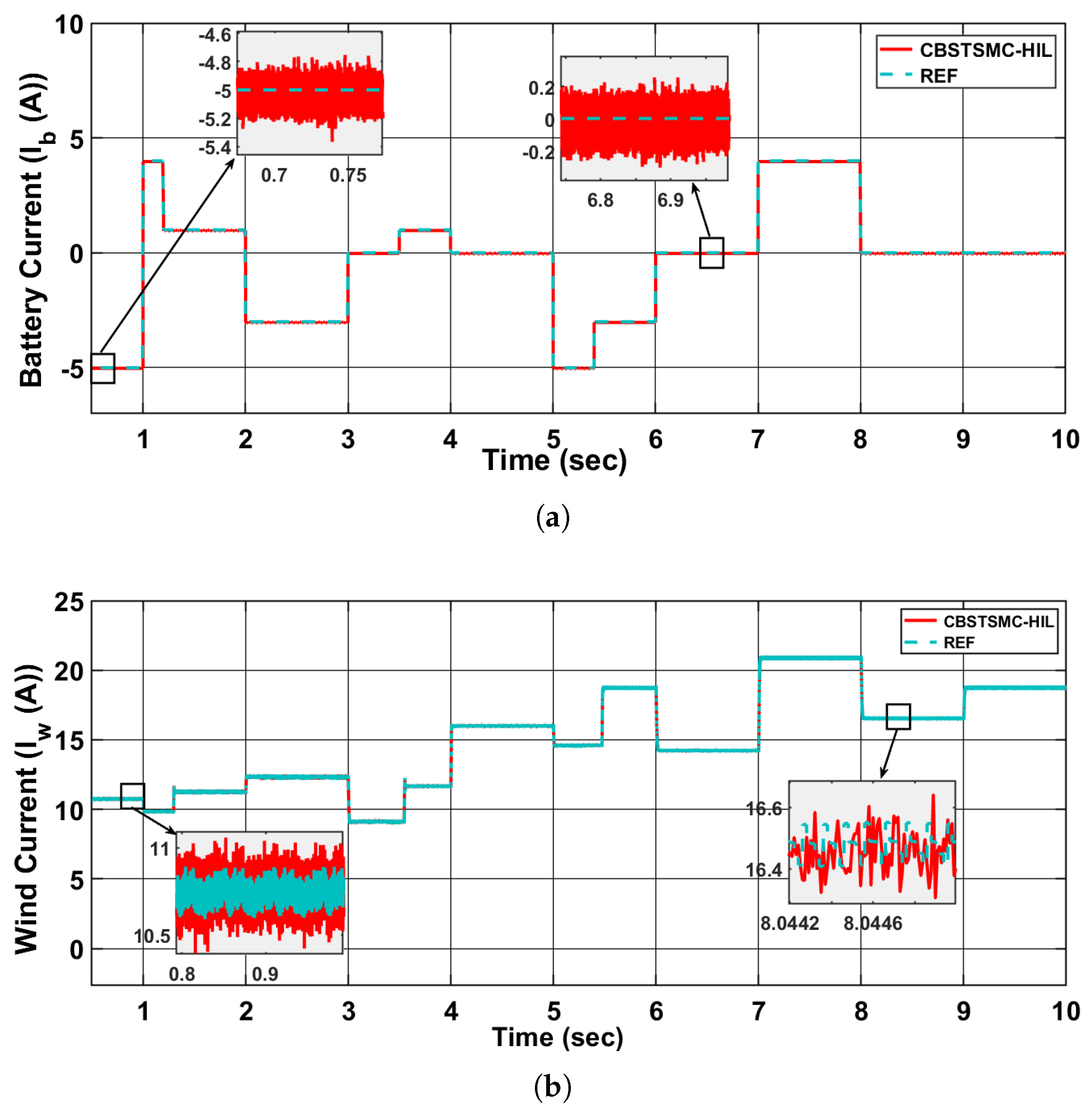
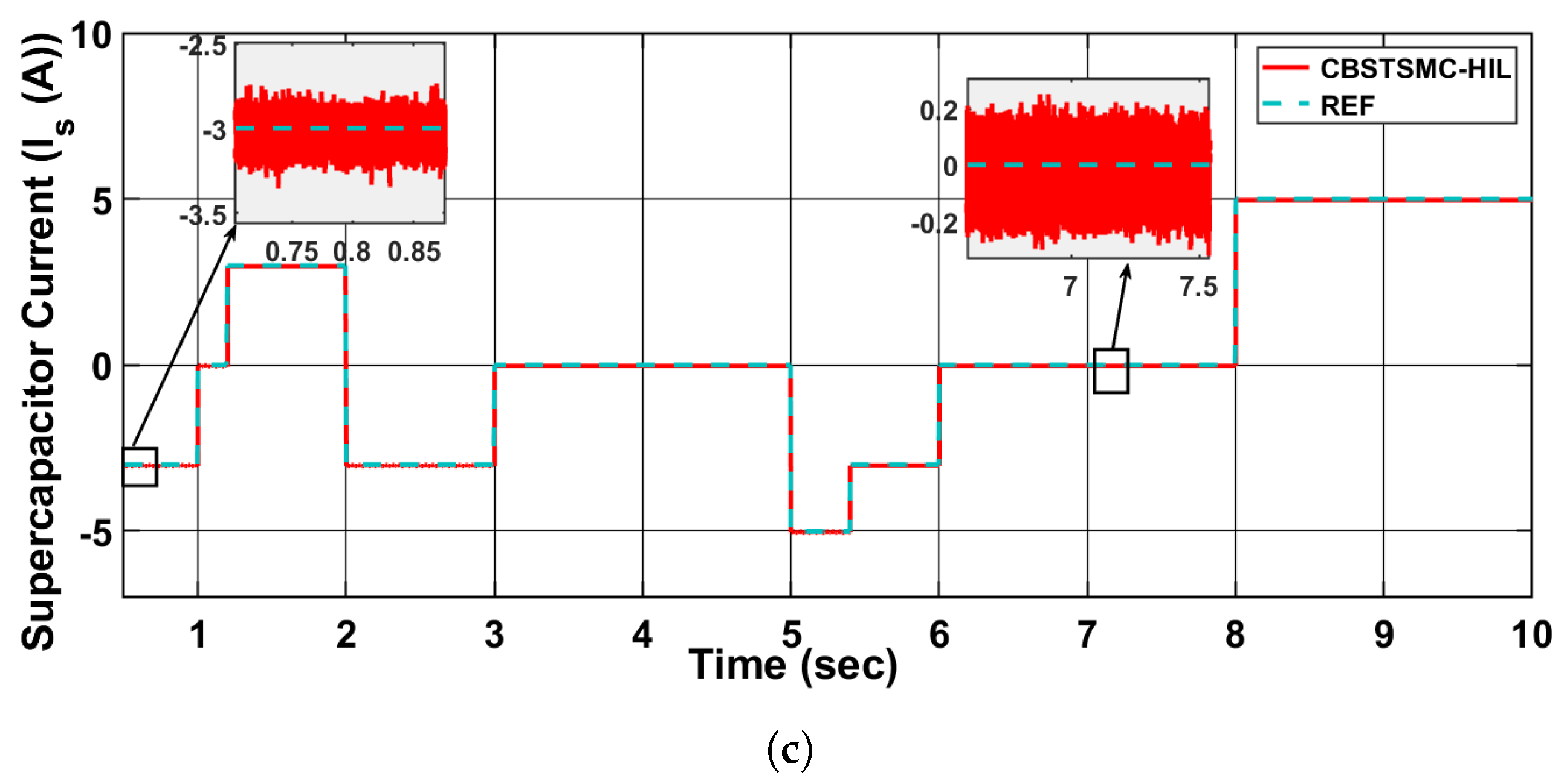
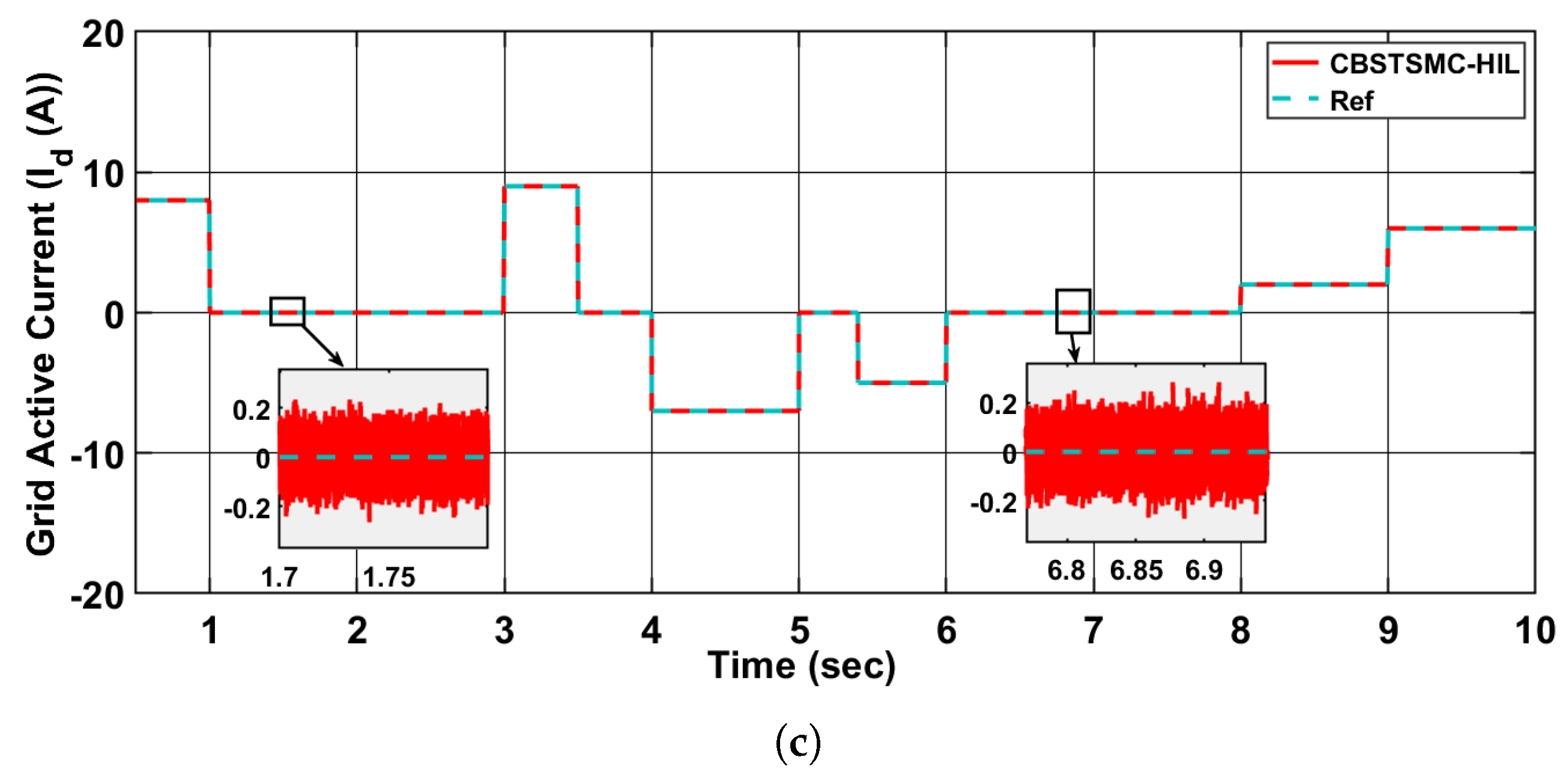
The experimental validation confirms that the CBSTSMC controller achieves fast tracking, strong robustness, and reliable dynamic performance under load transients and renewable generation variations, thereby ensuring its real-time feasibility.
Figure 11 and
Figure 12 exhibit the CIL results.
6. Conclusions
The proposed AC/DC hybrid microgrid system integrates renewable energy sources, including wind, with energy storage components such as batteries and supercapacitors. The system is designed to operate both in islanded and grid-connected modes, providing stable AC and DC bus voltages, managing power flow efficiently, and minimizing grid dependency. The system incorporates a wind energy source, battery storage, and a supercapacitor bank, all controlled using a dynamic control strategy. The CBSTSMC was employed to regulate the system’s operation. The controller’s primary objective was to improve dynamic performance, disturbance rejection, and voltage regulation. The system’s performance was validated through detailed simulations, and key metrics such as current waveforms from the battery, grid, and active components were analyzed. For instance, the grid active current showed a steady-state error of only 0.0531 A, while the wind current tracking was highly accurate with minimal fluctuations, ensuring efficient energy conversion. A significant feature of the system was the gain tuning of the CBSTSMC controller using the Improved Grey Wolf Optimizer (IGWO). IGWO was applied to find the optimal controller gains, which enhanced the controller’s response speed and tracking accuracy. This optimization process led to a substantial reduction in steady-state error and overshoot, achieving superior dynamic performance compared to traditional controllers. For example, the battery current was regulated with minimal overshoot, and rapid transitions between charging and discharging states were achieved, even during abrupt load changes. An Energy Management System (EMS) was implemented to control and optimize power flow in the hybrid energy setup. The EMS prioritizes renewable wind energy and coordinates battery and supercapacitor usage based on availability, ensuring minimal reliance on the grid. When wind power is insufficient, the system utilizes battery storage, and if the battery cannot meet the load, the supercapacitor is activated to handle short bursts of power demand. The grid is used as a last resort, and the system operates efficiently with minimal grid interaction. The Controller-in-the-Loop (CIL) testing was carried out using the Texas Instruments Delfino C2000 microcontroller, which validated the performance of the CBSTSMC in real-time conditions. The controller was implemented directly on the hardware, allowing for the assessment of the system’s response to dynamic conditions in a real-world setup. The CIL results confirmed the robust performance of the CBSTSMC, including its disturbance rejection capability and the accurate regulation of current and voltage. As part of future work, the proposed averaged model will be refined into a switching-level representation to incorporate PWM ripple and switching transients and enhance real-time validation fidelity.
