Review

Recent Advances in Numerical Modeling of Aqueous Redox Flow Batteries

1
School of Intelligent Manufacturing, Huzhou College, Huzhou 313000, China
2
Department of Thermal Science and Energy Engineering, University of Science and Technology of China (USTC), Hefei 230026, China
*
Author to whom correspondence should be addressed.
Energies 2025, 18(15), 4170; https://doi.org/10.3390/en18154170
Submission received: 30 June 2025 / Revised: 1 August 2025 / Accepted: 3 August 2025 / Published: 6 August 2025
(This article belongs to the Special Issue Advanced Energy Storage Technologies)

Abstract

Aqueous redox flow batteries (ARFBs) have attracted significant attention in the field of electrochemical energy storage due to their high intrinsic safety, low cost, and flexible system configuration. However, the advancement of this technology is still hindered by several critical challenges, including capacity decay, structural optimization, and the design and application of key materials as well as their performance within battery systems. Addressing these issues requires systematic theoretical foundations and scientific guidance. Numerical modeling has emerged as a powerful tool for investigating the complex physical and electrochemical processes within flow batteries across multiple spatial and temporal scales. It also enables predictive performance analysis and cost-effective optimization at both the component and system levels, thus accelerating research and development. This review provides a comprehensive overview of recent progress in the modeling of ARFBs. Taking the all-vanadium redox flow battery as a representative example, we summarize the key multiphysics phenomena involved and introduce corresponding multi-scale modeling strategies. Furthermore, specific modeling considerations are discussed for phase-change ARFBs, such as zinc-based ones involving solid–liquid phase transition, and hydrogen–bromine systems characterized by gas–liquid two-phase flow, highlighting their distinctive features compared to vanadium systems. Finally, this paper explores the major challenges and potential opportunities in the modeling of representative ARFB systems, aiming to provide theoretical guidance and technical support for the continued development and practical application of ARFB technology.

1. Introduction

The escalating global demand for sustainable energy storage solutions has intensified research into advanced battery technologies [1]. Most renewable energy sources, such as solar and wind, are inherently intermittent, creating temporal and spatial mismatches between energy generation and consumption [2]. To overcome these challenges and ensure grid stability, the development of efficient energy storage systems is essential [3]. Among these, aqueous redox flow batteries (ARFBs) have garnered significant attention for large-scale applications such as grid connection and renewable energy integration due to their inherent advantages, including flexible design, long operational life, fast response times, and enhanced safety [4,5,6,7]. Meanwhile, unlike conventional static batteries, flow batteries store energy in external electrolyte tanks, allowing for independent scaling of power and energy capacities [8]. Despite their promising features, the widespread market penetration of ARFBs is currently impeded by several critical issues [9,10]. Key challenges include electroactive species crossover through the ion-exchange membrane, leading to capacity loss and coulombic efficiency degradation [11]. Undesirable side reactions, such as hydrogen evolution at the negative electrode and oxygen evolution at the positive electrode [12], also contribute to performance degradation and electrolyte imbalance [13]. Furthermore, the optimization of structural geometries at various scales and the identification of optimal battery operating conditions remain significant hurdles [14,15,16]. These complexities necessitate a profound understanding of the intricate interplay between structural design parameters and multi-variable operational factors within the battery system.
Numerical modeling have emerged as indispensable tools for addressing these challenges, offering a cost-effective and efficient approach to comprehending the underlying mechanisms across different spatial and time scales, and for optimizing reaction interfaces, battery components, and the entire system [17]. For instance, in the context of the widely studied all-vanadium redox flow battery (VRFB), prior studies have extensively utilized numerical modeling to investigate various aspects of VRFBs. For instance, dynamic lumped parameter models have been developed to understand the effects of electrolyte flow rate, concentration, electrode porosity, temperature, and applied current on unit cell performance [18]. Comprehensive models incorporating mass, charge, energy, and momentum transport have provided insights into hydrogen and oxygen evolution effects, temperature distribution, and their impact on charge–discharge characteristics [19,20]. Moreover, modeling efforts have focused on optimizing cell structure, exploring flow field designs (e.g., interdigitated and serpentine), and analyzing the influence of electrode compression and surface properties on battery performance [21,22] The Donnan effect (uneven distribution of ions across the membrane) and its influence on vanadium crossover have also been investigated through transient electrochemical models [23].
Existing literature typically classifies aqueous redox flow batteries based on battery chemistries. For example, some reviews focus on zinc-based systems [24,25] but do not highlight the modeling challenges arising from phase transition phenomena. In contrast, this work starts from the perspective of phase transformation mechanisms and emphasizes their impact on model construction, proposing a more mechanism-oriented modeling framework. A systematic discussion of microscale and cross-scale modeling approaches, which are rarely covered in existing reviews [26,27], is also included. These additions serve to better highlight the uniqueness and significance of the study.
In response to the evolving landscape of ARFB technology, this review summarizes recent advances in numerical modeling by building upon foundational studies and introducing new insights. The paper begins by using VRFBs as a representative system to introduce their fundamental configuration and electrochemical reaction mechanisms. This is followed by a systematic discussion of key physicochemical processes relevant to modeling, including electrode reaction kinetics, mass transport within porous electrodes and ion-exchange membranes, and thermal effects during operation. The review then provides a comprehensive overview of commonly used modeling approaches, ranging from zero-dimensional and multi-dimensional porous media models to microscale and multi-scale coupled frameworks. The strengths and limitations of each method are critically evaluated. Subsequently, the discussion extends to other representative aqueous systems involving phase changes, such as zinc-based and hydrogen–bromine flow batteries, highlighting their distinctive modeling challenges. The final part of the paper identifies current limitations and unresolved issues in ARFB modeling and outlines future research directions. This structured review provides a timely and comprehensive perspective to support the continued advancement and practical application of ARFB modeling in the context of renewable energy integration.
In response to the evolving landscape of aqueous flow battery technology, this paper reviews recent advancements in numerical modeling, building upon foundational research and extending it with new insights. First, the VRFB is taken as a representative example to introduce its fundamental structure and electrochemical reaction principles. Key physicochemical processes, including electrode reaction kinetics, mass transport mechanisms within porous electrodes and ion-exchange membranes, and thermal effects during operation, are systematically discussed to lay a theoretical foundation for model development. Based on this, mainstream modeling strategies and methodologies are comprehensively summarized, ranging from zero-dimensional lumped parameter models and one- to multi-dimensional porous media models to microscale and multi-scale coupled modeling frameworks. The applicability, advantages, and limitations of each approach are critically analyzed. Subsequently, other representative aqueous flow battery systems that feature different modeling methods due to phase change involvement, such as zinc-based and hydrogen–bromine flow batteries, are introduced and compared in detail. Finally, this work outlines the current limitations and unresolved challenges in aqueous flow battery modeling, highlighting key areas for future research and development. By consolidating these insights, this work provides a timely and comprehensive perspective on modeling strategies, thereby promoting the development of ARFBs to better support the integration of renewable energy sources.

2. Key Processes and Physicochemical Phenomena in ARFBs

2.1. Flow Battery Structure

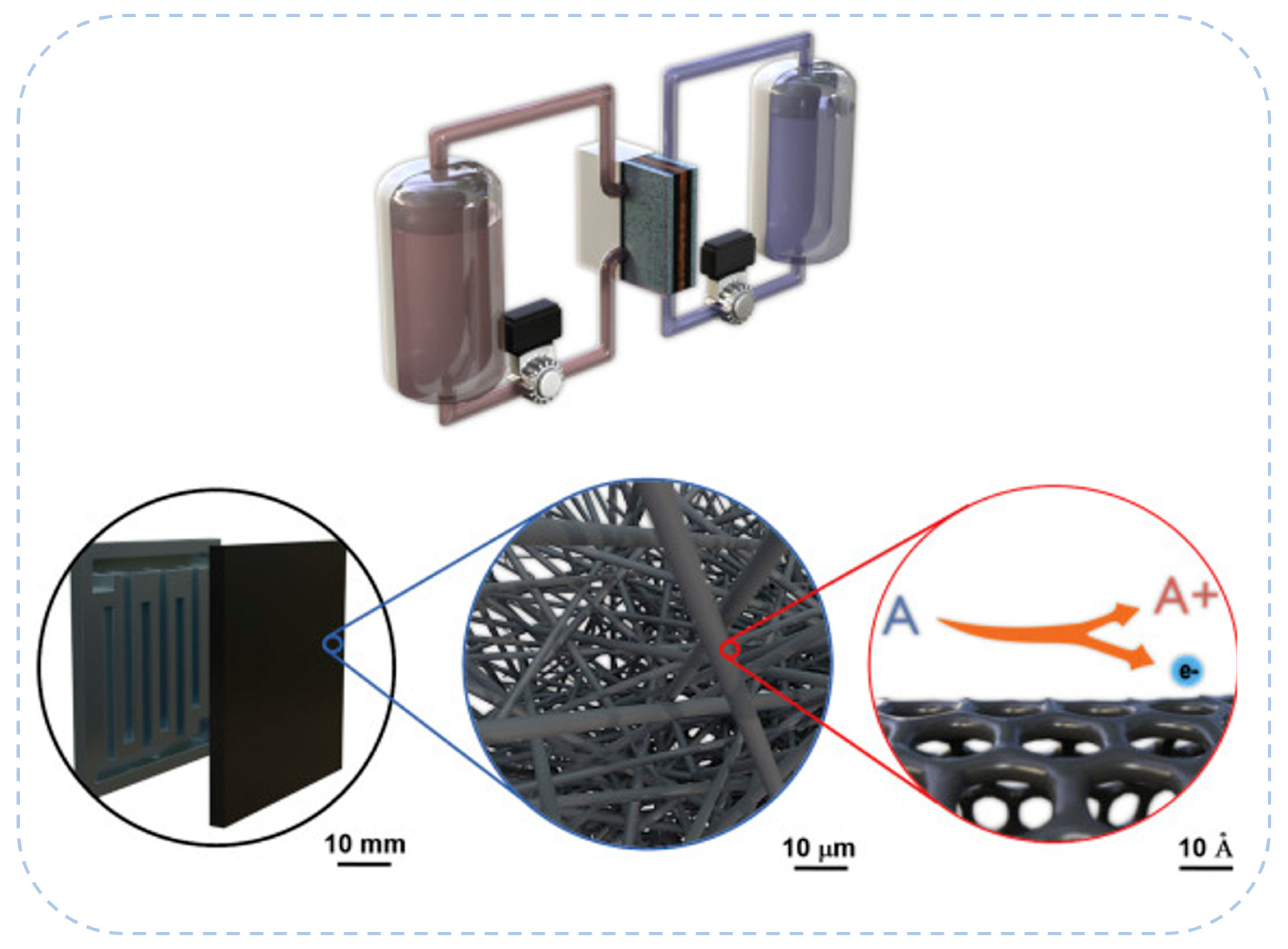
A typical redox flow battery, taking a VRFB as an example, as depicted in Figure 1, comprises two external electrolyte tanks that store solutions containing soluble redox-active species. These electrolytes are continuously circulated by pumps through the electrochemical cell stack, where energy conversion takes place. The battery stack consists of multiple identical unit cells, each featuring a pair of porous carbon electrodes that function as the positive and negative electrodes, where oxidation and reduction reactions take place. Positioned between the electrodes is an ion exchange membrane that selectively permits the transport of specific ions (e.g., protons), thereby maintaining charge neutrality while suppressing the crossover of active species, which is essential for reducing capacity decay and improving coulombic efficiency [28].
Flow field plates, typically fabricated from graphite or composite materials, surround the electrode–membrane assembly [29,30]. These plates are engineered with serpentine or interdigitated channels to ensure uniform electrolyte distribution and enhance convective mass transport, thus mitigating concentration polarization [31,32]. Embedded current collectors facilitate electron transfer between the electrodes and the external circuit, minimizing interfacial resistance and supporting efficient power delivery. The system also incorporates a power management and control unit to monitor and regulate critical operational parameters, including voltage, current, temperature, and electrolyte flow rate, thereby ensuring stable and safe operation. In high-power applications, thermal management components need be integrated to dissipate excess heat generated during intense charge–discharge cycles [33]. A key advantage of RFBs lies in their inherently modular architecture, which allows the decoupled scaling of energy and power: energy capacity is governed by the volume and concentration of electrolytes in the tanks, while power output depends on the number and size of cells in the stack [34]. This design flexibility, combined with the use of non-flammable aqueous electrolytes, offers high operational safety, extended service life, and scalability, making RFBs particularly attractive for large-scale, long-duration energy storage.
Among the various chemistries developed, the VRFB represents the most mature and extensively studied system. By employing vanadium ions in multiple oxidation states on both sides of the cell, VRFBs eliminate the issue of cross-contamination between electrolytes, thus improving long-term cycling performance and system durability. Specifically, the redox reactions involved in VRFB operation are as follows [35]:
Negative electrode: V2+ ⇌ V3+ + e (E = −0.26 V vs. SHE)
Positive electrode: VO2+ + 2H+ + e ⇌ VO2+ + H2O (E+ = +1.00 V vs. SHE)
Overall cell reaction: VO2+ + V2+ + 2H+ ⇌ VO2+ + V3+ + H2O (E0 = 1.26 V)
The VRFB enables reversible energy storage and release by utilizing vanadium ions in different oxidation states at the negative (V2+/V3+, −0.26 V) and positive (VO2+/VO2+, +1.00 V) electrodes thus offering a theoretical voltage of 1.26 V. The electrode potentials given in the above reactions (E = –0.26 V vs. SHE and E+ = +1.00 V vs. SHE) are referenced against the standard hydrogen electrode (SHE). These values are measured under standard conditions, i.e., 1 M concentrations of all species, a temperature of 25 °C, and a pressure of 1 atm.

2.2. Porous Electrode Structure and Performance

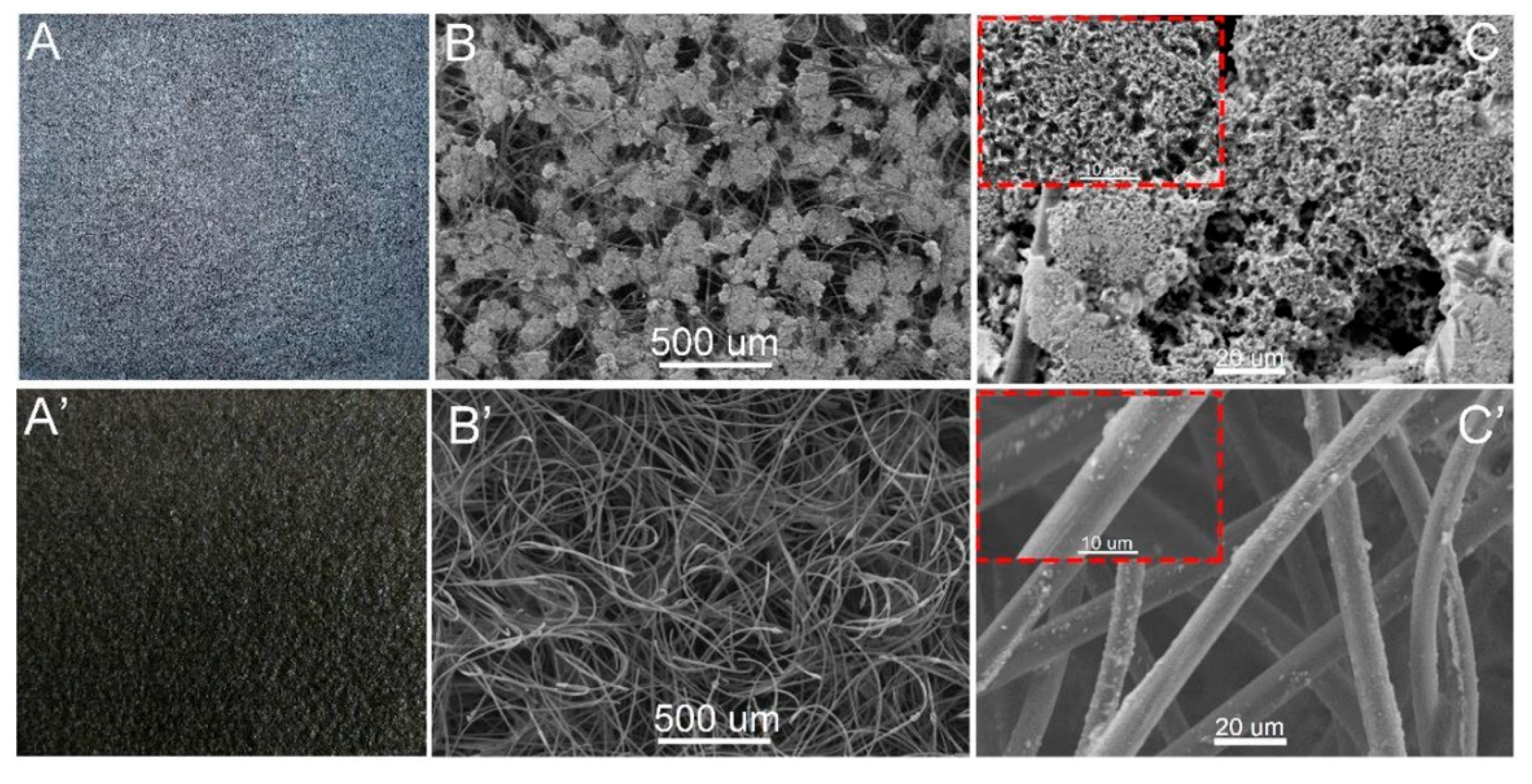
The porous electrode in ARFBs not only serves as the primary site for electrochemical reactions but also directly influences electrolyte transport, charge transfer efficiency, and the occurrence of side reactions, as illustrated in Figure 2. Therefore, a deep understanding and optimization of the electrode’s structural parameters and material properties are crucial for enhancing the energy efficiency, power density, and lifespan of ARFB systems.
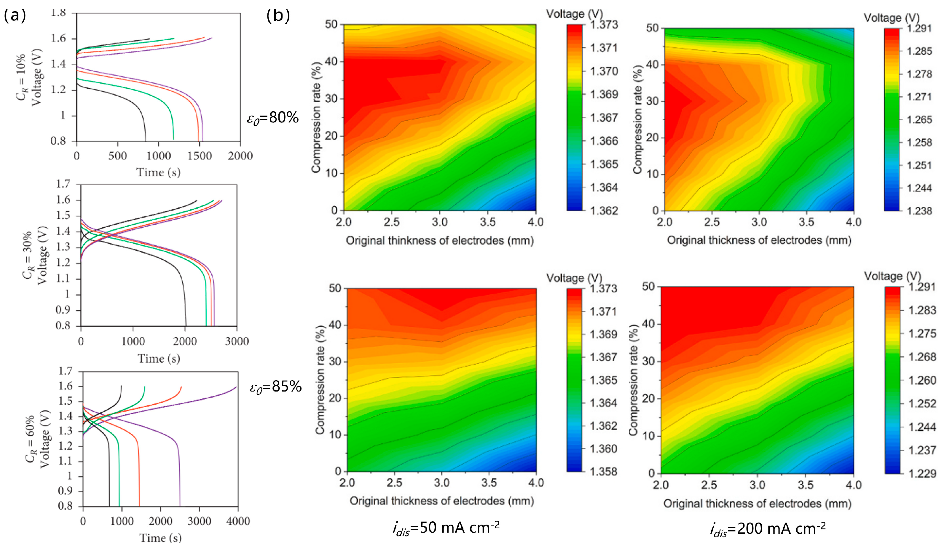
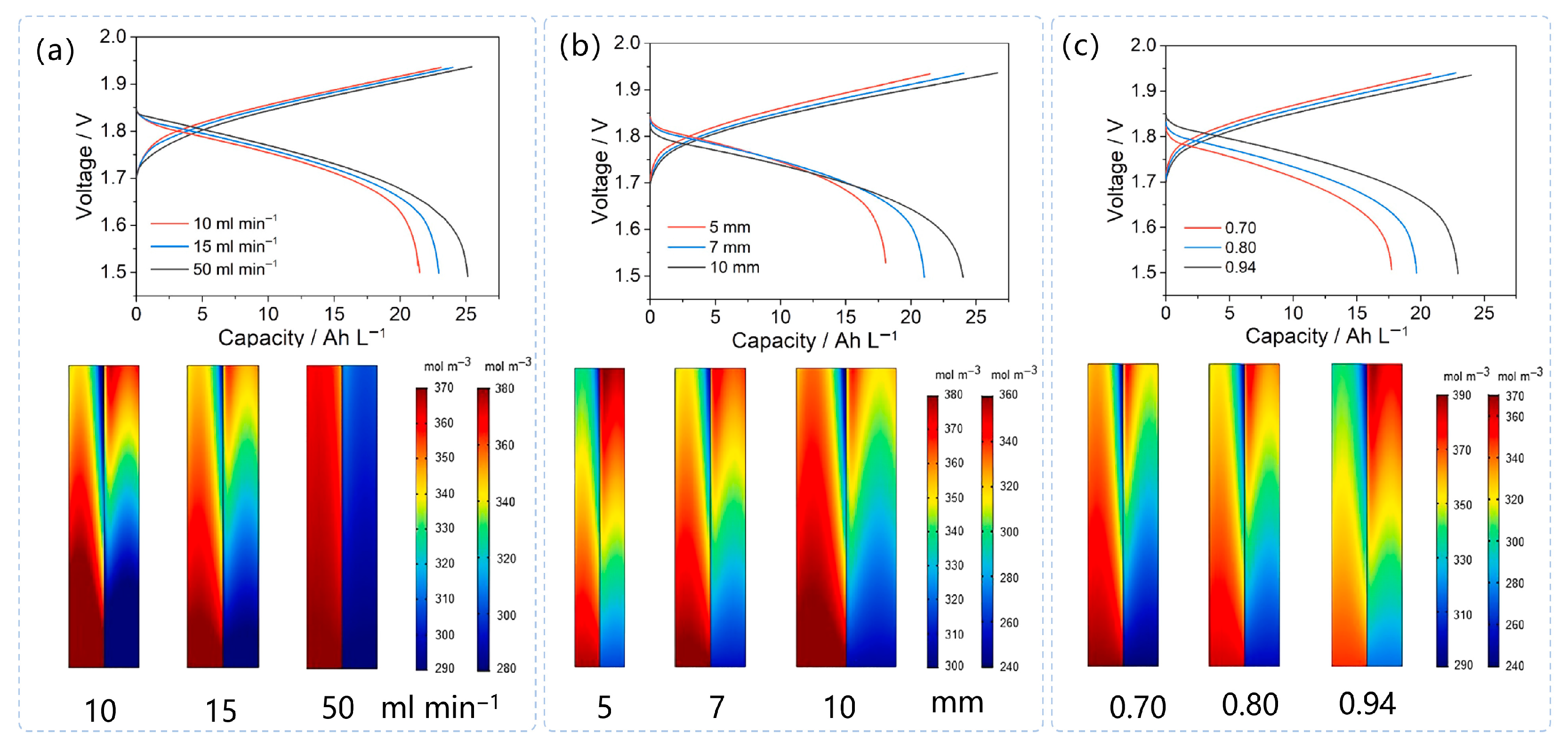
Among the various parameters affecting the performance of redox flow batteries, porosity is one of the key factors governing electrochemical reaction efficiency and mass transport within the electrode [37,38]. A suitably high porosity can significantly increase the electrochemically active surface area, thereby enhancing reaction kinetics and reducing activation overpotential, ultimately improving overall battery performance [39]. For example, Tai et al. demonstrated that changes in porosity, achieved by adjusting the compression ratio of carbon fiber electrodes and the electrolyte flow rate, have a pronounced effect on the charge–discharge behavior of the battery, as shown in Figure 3a [40]. An appropriate porous structure also facilitates efficient electrolyte transport and reduces mass transfer resistance. However, excessive porosity may compromise the mechanical strength of the electrode and increase ohmic losses due to discontinuous conductive pathways. To accurately capture the influence of pore structure on fluid and species transport in modeling, porosity is typically incorporated as a critical parameter into transport equations for porous media. As illustrated in Figure 3b, for electrodes with high initial porosity (≥85%), discharge voltage increases with compression ratio, with more pronounced improvements observed under higher current densities [41]. In contrast, for electrodes with low initial porosity (<80%), discharge voltage peaks at a compression ratio of approximately 40%, beyond which further compression leads to performance degradation. As both electrode thickness and current density increase, the optimal compression window narrows, indicating that excessive compression should be avoided under high current densities. To further optimize the porosity distribution, topology optimization was employed to reconstruct the spatial porosity profile in regions downstream of the flow field inlet. It was shown that introducing a moderately reduced porosity in these regions effectively enhances the active surface area and improves product transport [42].
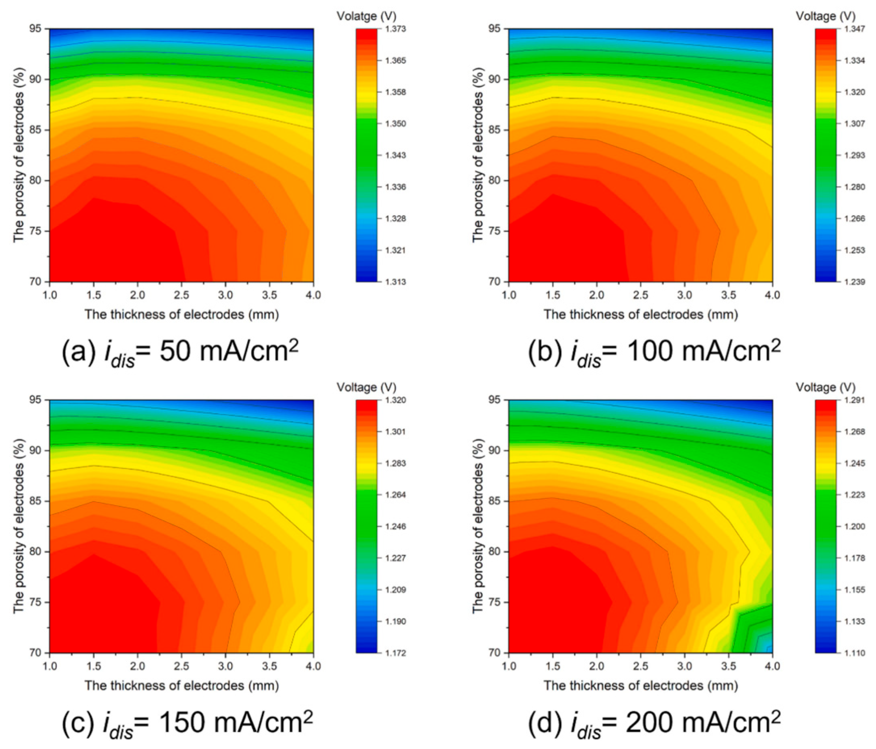
Electrode thickness has a dual effect on the performance of ARFBs. On one hand, increasing the thickness provides a larger reactive volume, thereby enhancing the battery’s capacity and energy density [43]. On the other hand, thicker electrodes increase the diffusion path for electrolyte species, potentially resulting in higher concentration overpotentials, especially at high current densities. He et al. [44] developed an integrated model to investigate the combined effects of electrode structure and surface properties, and reported that a modified carbon fiber electrode with a thickness of 0.5 mm and a porosity of 0.9 exhibited superior electrochemical performance (Figure 4a). As illustrated in Figure 4b, the energy storage capacity increases significantly when the electrode thickness increases from 2 mm to 6 mm [45]. However, a further increase to 8 mm results in a decline in capacity, indicating a performance optimum at moderate thickness. Furthermore, electrode thickness is strongly coupled with compression ratio, this coupling also affects porosity, which in turn influences overall battery performance. The combined effects of electrode thickness and porosity are further depicted in Figure 5. When the electrode thickness is within 1.0–3.0 mm and the porosity ranges from 70% to 85%, the battery achieves relatively high discharge voltages. However, this high-voltage operating window narrows with increasing current density. For electrodes with porosity exceeding 90%, increasing thickness has little impact on discharge voltage at low current densities (<100 mA cm−2). In contrast, at higher current densities, thicker electrodes lead to a decline in discharge voltage. This is because, although increased thickness provides more reaction sites and reduces electrochemical overpotentials, it simultaneously hampers mass transport and increases concentration overpotentials. This effect is especially pronounced near the membrane on the outlet side, where the concentrations of active species (VO2+ and V2+) drop significantly. Ultimately, the growing concentration overpotential outweighs the benefit of reduced electrochemical overpotential, resulting in decreased discharge performance.
In addition to structural properties, surface characteristics and modifications of electrode materials are also critical to enhancing performance of ARFBs. Carbon felt is a commonly used electrode material in ARFBs, and its surface modification can significantly improve electrochemical kinetics. For example, Kim et al. [46] reported that the addition of W6+ catalysts to the electrolyte led to tungsten deposition on the electrode surface, which enhanced the reaction activity and improved battery efficiency by 2–3%. Similarly, Devi et al. demonstrated that modifying carbon felt with carbon nanotubes (CNTs) greatly enhanced battery performance [47]. CNTs provide more active sites and better electron conduction pathways, effectively reducing charge transfer resistance. In numerical simulations, such modifications are usually represented by increased exchange current density or reaction rate constants, reflecting improvements in reaction kinetics.
Flow field design is closely coupled with the structure of the porous electrode and plays a critical role in governing electrolyte transport and distribution within the electrode [48,49]. Achieving a uniform distribution of electrolyte is essential for maximizing electrode utilization and minimizing mass transport losses [50]. As shown in Figure 6, previous studies have shown that interdigitated flow fields offer superior flow uniformity and lower pressure drops, while serpentine flow fields can enhance electrochemical performance, albeit at the expense of higher auxiliary energy consumption [51]. This highlights the inherent trade-off between performance improvement and system energy efficiency [52]. Building upon this, recent research has increasingly focused on the coordinated optimization of flow field and electrode design. For example, Ma et al. employed a three-dimensional model to investigate the impact of flow field configurations on reaction distribution within the negative half-cell of a VRFB, underscoring the importance of coupling flow channel architecture with electrode structure to enhance overall system performance [31].
The porosity, thickness, surface properties, and modification methods of the electrodes, along with the synergistic design of the flow field structure, collectively determine the reaction efficiency and energy performance of ARFBs at multiple levels. Integrating experimental and modeling approaches to systematically optimize these factors is a key pathway toward achieving high-performance and high-stability ARFB systems.

2.3. Mass Transport Processes

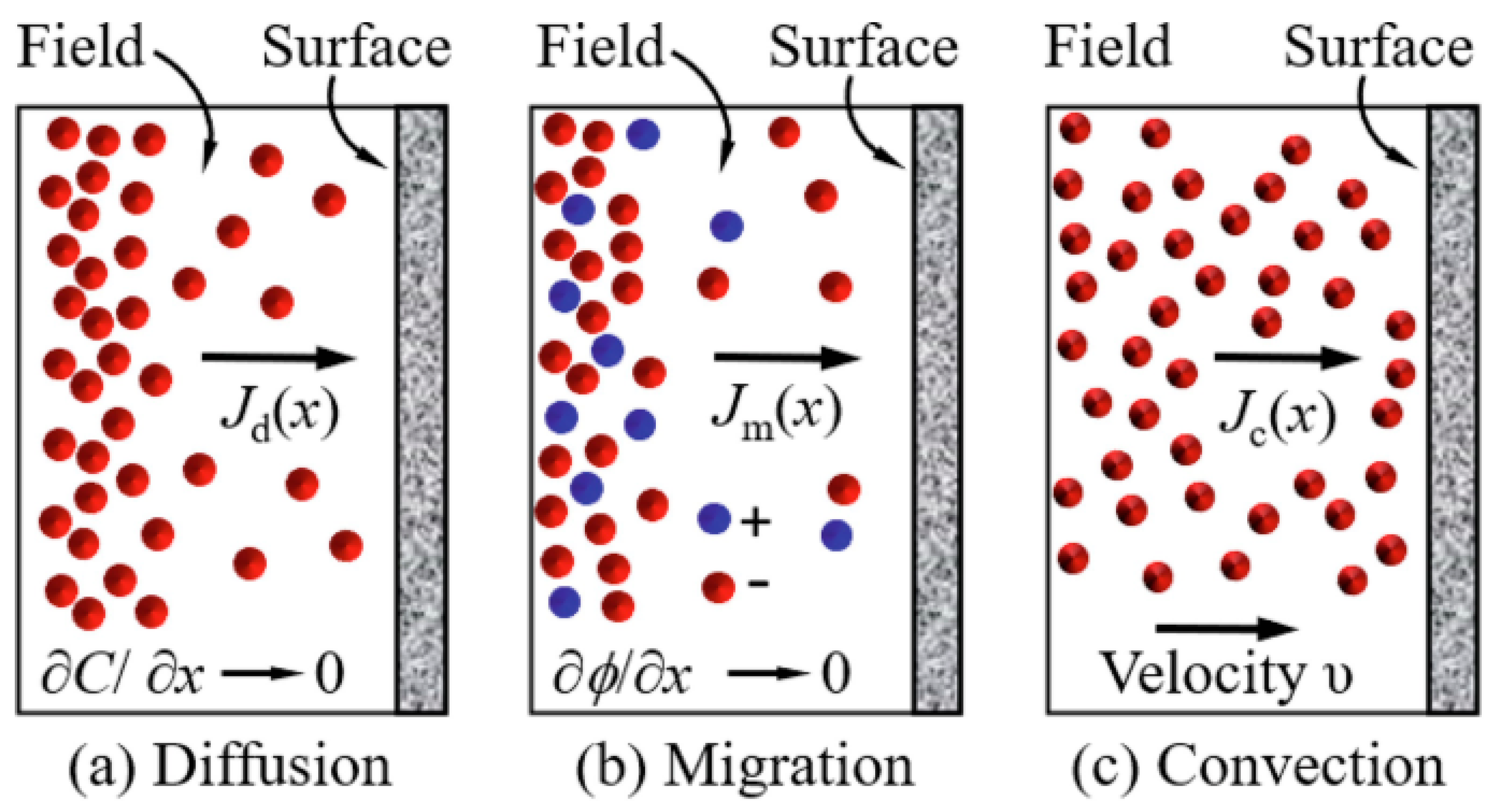
Mass transport within the porous electrode is one of the key limiting factors affecting the performance of ARFBs. As shown in Figure 7, ions are transported via convection, diffusion, and migration within the porous structure [53]. At high current densities, transport limitations can lead to a significant increase in concentration overpotential, thereby reducing the efficiency and power density of the battery [54]. Consequently, optimizing electrode architecture to enhance convective transport and shorten ionic diffusion pathways is a crucial strategy for performance improvement. For instance, incorporating layered structures or graded porosity within the electrode has been shown to facilitate electrolyte infiltration and distribution, effectively alleviating mass transport limitations [42].
In the numerical modeling of porous electrodes, the transport of active species within the electrolyte is typically described by the mass conservation equation. For a given species i, this equation takes the following form [24]:
t ( ε c i ) + N i = S i
where ci denotes the concentration of species i, ε is the electrode porosity, t is time, N i represents the flux of species i, and Si is a source or sink term accounting for the rate of production or consumption due to electrochemical reactions. This formulation captures both the temporal evolution and spatial distribution of active species within the porous matrix, providing a fundamental framework for analyzing mass transport behavior and performance limitations in ARFBs.
To accurately characterize the transport behavior of active species within the porous structure of electrodes, the extended Nernst–Planck equation is commonly employed. This formulation accounts for three principal mass transport mechanisms: convection, diffusion, and migration. The species flux N i can be mathematically expressed as [54]:
N i = D i e f f c i z i c i D i e f f F R T ϕ l + v c i
where D i e f f is the effective diffusion coefficient, which incorporates the influence of electrode porosity and tortuosity on the diffusion pathway; zi is the ionic charge, F is the Faraday constant, R is the universal gas constant, T is the absolute temperature, ϕl is the liquid-phase potential, and v is the convective velocity of the electrolyte. This extended equation comprehensively describes the transport behavior of charged species in porous electrodes by combining the effects of diffusion driven by concentration gradients, migration driven by electric potential gradients, and convection driven by fluid flow. It is particularly well-suited for multiphysics coupled systems such as VRFBs.
At high current densities, transport limitations can lead to a significant increase in concentration overpotential, thereby reducing the efficiency and power density of the battery [54]. Consequently, optimizing electrode structures to shorten diffusion paths and enhance convective transport is a critical strategy for performance improvement. For instance, introducing layered architectures or graded porosity within the electrode has been shown to improve electrolyte permeability and distribution, effectively mitigating transport-induced polarization [42]. Moreover, to accurately characterize the actual flow behavior of the electrolyte in high-porosity electrodes (e.g., ε > 0.6), the classical Darcy’s law is often insufficient in terms of predictive accuracy. In such cases, the Brinkman equation can be employed by introducing a shear term to capture the transition effects between porous and free-flow regions. The equation is given as follows [55]:
μ K v = p + μ [ v + ( v ) T ]
where μ is the dynamic viscosity of the electrolyte, p is the pressure, K is the permeability closely related to the porous structure, which can be estimated using the Kozeny–Carman equation [56]:
K = d p 2 ε 3 180 ( 1 ε ) 2
where dp denotes the diameter of the carbon fiber. This equation maintains the continuity of the velocity field and more accurately depicts flow characteristics within high-porosity electrodes, making it particularly suitable for modeling internal flow and mass transport in high-porosity materials such as carbon felt used in ARFBs.
Meanwhile, the charge conservation equations in both the liquid and solid phases are fundamental for describing the potential distribution within porous electrodes:
i e + i s = 0
The subscripts e and s represent the electrolyte phase and the electrode phase, respectively.

2.4. Electrode Reaction Kinetics

The Butler–Volmer equation is widely used to describe the reversible electrochemical reactions occurring within the porous electrodes of ARFBs. This equation characterizes the relationship between the electrochemical reaction’s transfer current density (j+/j) and the activation overpotential (η+) on the surfaces of the positive and negative porous electrodes [57,58,59].
The transfer current density in porous electrodes is controlled by the Bulter-Volmer equations as expressed as:
j + = a F k + ( c v 4 + s ) α 1 , c ( c v 5 + s ) α 1 , a [ exp ( α 1 , c F η + R T ) exp ( α 1 , a F η + R T ) ]
j = a F k ( c v 2 + s ) α 1 , c ( c v 3 + s ) α 1 , a [ exp ( α 1 , c F η R T ) exp ( α 1 , a F η R T ) ]
The exchange current density is
j 0 + = a F k + ( c v 4 + s ) α 1 , c ( c v 5 + s ) α 1 , a
j 0 = a F k ( c v 2 + s ) α 1 , c ( c v 3 + s ) α 1 , a
The activation overpotential is
η + = ϕ s ϕ l E +
η = ϕ s ϕ l E
where a is the specific surface area of the porous electrode, α1,c and α1,a are the charge transfer coefficients for the cathode and anode, respectively, k+ and k are the reaction rate constants for the positive and negative electrodes, ϕ s and ϕ l represent the potentials of the electrode and the electrolyte, respectively, and E is the standard electrode potential.
At present, the electrochemical reaction kinetics of ARFBs have been relatively well established, providing a solid foundation for structural optimization, operational strategy development, and cycle performance evaluation under various working conditions [17]. Based on this, validated modeling approaches have been employed to effectively explore the optimal operating parameters for the commercial application of ARFBs. Furthermore, by integrating numerical simulations with experimental investigations, the long-term performance degradation behavior of ARFBs has been systematically assessed, offering valuable theoretical support and practical guidance for improving stability and optimizing performance in real-world engineering applications.

2.5. Transport Theory in Membranes

Permselectivity and ionic conductivity are the core functions of the membrane in ARFBs. The primary role of the membrane is to separate the positive and negative electrolytes, preventing direct mixing of active species while allowing charge carriers (typically protons or OH) to pass through, thereby maintaining electro-neutrality during the battery’s cycling process. An ideal membrane should possess high ion selectivity, permitting the transport of desired ions while effectively preventing the crossover of redox ions such as V2+, V3+, VO2+, and VO2+, thereby minimizing capacity loss and undesirable side reactions. Additionally, it should exhibit excellent ionic conductivity to reduce internal resistance and improve the overall energy efficiency of the battery [60].
However, high ionic conductivity and low vanadium ion permeability are often mutually constraining factors. Improving ionic conductivity typically involves increasing membrane porosity or reducing membrane thickness, both of which can facilitate vanadium ion crossover and increase cross-contamination. For example, the Nafion series of perfluorosulfonic acid membranes are widely used in ARFBs due to their excellent proton conductivity and chemical stability, yet their selectivity toward vanadium ions remains a limitation [61].
The transport of species through the membrane is primarily driven by a combination of diffusion, migration, and convection. These mechanisms can be collectively described by the Nernst–Planck equation, which is used to represent the crossover flux of electroactive species within the membrane [62,63].
N i = D i e f f c i z i c i D i e f f R T F ϕ + v c i
where the first term is driven by the concentration gradient of the substance, the second term is determined by the electric field, and the third term is driven by the pressure difference across the membrane.
In ARFB modeling, a narrow interfacial region exists between the electrolyte and the ion-exchange membrane. This region is characterized by discontinuities in ion concentration and electrical potential, a phenomenon known as the Donnan effect [64]. Although electroactive species and current flux are continuous at the interface, the membrane’s super-selectivity leads to jumps in both concentration and potential. Early ARFB models did not account for this effect. Subsequently, researchers incorporated it into their modeling frameworks to more accurately describe the transport processes and ion selectivity mechanisms. Nowadays, considering the Donnan effect at the membrane-electrolyte (M-E) interface has become an indispensable and important factor in the numerical simulation of flow batteries [65].
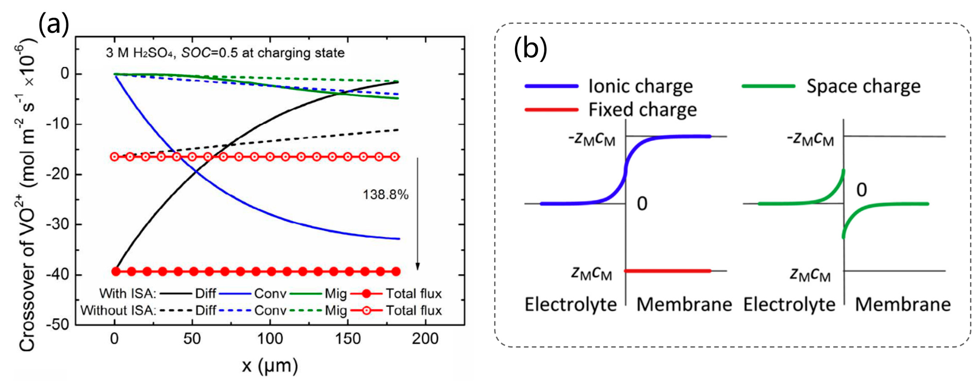
To investigate the transmembrane transport behavior of vanadium ions in VRFBs, a numerical model incorporating the Donnan effect was developed by introducing an interfacial sub-model based on electrochemical potential equilibrium at the M-E interface [64]. As shown in Figure 8, under a discharge current density of 50 mA cm−2 and a state of charge (SOC) of 0.5, significant concentration discontinuities of H+, HSO4, and vanadium ions are observed across both cation- and anion-exchange membranes, highlighting the presence of the Donnan effect at the M-E interfaces. To further improve modeling accuracy, Y. Lei et al. proposed a novel ion-selective adsorption model that considers only mobile ions distributed within membrane pores, while incorporating the Donnan effect [65]. As illustrated in Figure 9a, this model enables more accurate prediction of VO2+ crossover behavior, including diffusive, migrative, and convective flux components. Moreover, Y. Lei et al. developed a continuous Donnan-effect model by coupling the Poisson equation with the Nernst–Planck equation to capture the continuous distribution of variables at the M-E interfaces [23]. As shown in Figure 9b, the simulation results reveal a gradual transition in ionic charge from zero in the electrolyte to -ZMCM within the membrane due to the presence of fixed charges, forming a typical diffusion double layer structure.
Beyond the crossover of vanadium ions, the migration of water across the membrane between the positive and negative electrolytes is also a common and challenging issue in flow batteries [66]. Typically, the transport of vanadium ions is accompanied by the cross-membrane transport of water. This not only leads to the precipitation of electrolyte on one side but also dilutes the solution on the other side [67]. However, the cross-membrane migration of water can also promote proton migration, which aids in charge balance. Therefore, it’s essential to thoroughly analyze and investigate the phenomenon of water cross-membrane transport in flow batteries. Currently, the three main mechanisms identified for water crossover are the migration of vanadium ions, osmotic pressure gradient, and electro-osmotic drag. To characterize water transport across the membrane, a new water balance equation is introduced into the model [68]:
( ε C w ) c i m t + ( D w e f f C w + v C w ) = S W
D w e f f = ε τ D w
where τ is the electrode tortuosity, which describes the convoluted path of pore channels within the porous electrode. Dw is the diffusion coefficient of water. To calculate the transport properties within the membrane, the water content of the membrane, λ, is expressed in terms of its water activity, a, as follows:
a = C w g R T P sat
λ = λ g = 0.043 + 17.81 a 39.85 a 2 + 36 a 3 ( 0 < a 1 ) λ l = 22
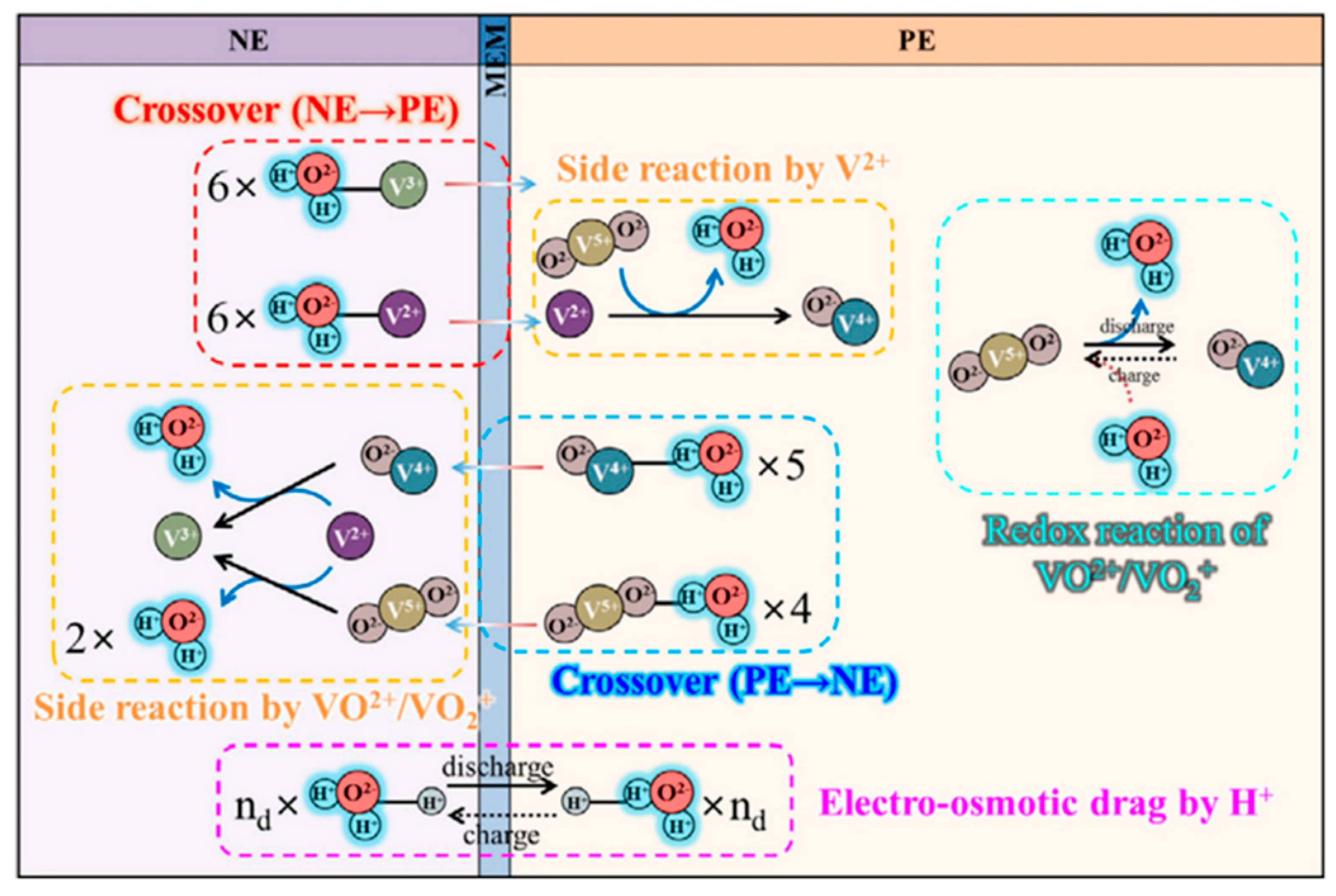
As illustrated in Figure 10, the water source term Sw comprehensively accounts for several key processes: it reflects the consumption and generation of water during redox reactions at the positive electrode, as well as water transport associated with vanadium ion crossover through the membrane [69]. In addition, Sw includes water produced from side reactions at both the positive and negative electrodes, electro-osmotic drag effects, and water diffusion driven by concentration gradients.

3. Modeling Approaches and Scales for Aqueous Redox Flow Batteries

The scale division of redox flow batteries typically includes the pore scale, electrode scale, and system scale. The pore scale (micron level) describes local mass transport and electrochemical reaction behaviors within the porous electrode structure. The electrode scale (millimeter level) focuses on the overall concentration and potential distribution, as well as the uniformity of reactions within the electrode. The system scale (from centimeters to meters) involves macroscopic performance aspects such as fluid distribution, current density fields, and thermal management across the entire battery or stack.
Corresponding to these spatial scales, various modeling approaches have been developed to investigate the complex transport and electrochemical processes within ARFBs. Modeling approaches for ARFBs cover a wide range of spatial and temporal scales, from the macroscopic system level to the microscopic electrode and electrolyte interface. Each modeling framework offers a specific balance between computational efficiency and predictive accuracy, tailored to address different research objectives [70,71]. In the previous section, a macroscopic continuum model was employed to simulate the internal states and electrochemical processes within the battery. This was achieved by solving a set of governing equations, including conservation of mass, momentum, charge, and energy [70]. The model effectively captures key transport phenomena and electrochemical reaction kinetics, such as the valence transitions between VO2+ and VO2+ at the positive electrode, and between V3+ and V2+ at the negative electrode [72,73,74]. It also provides insights into how the flow field distribution influences mass transport behavior [49,75]. In addition to the continuum approach, other commonly used modeling methods include zero-dimensional lumped parameter models, microscale models, and multi-scale frameworks, each offering complementary perspectives for analyzing different aspects of battery performance.

3.1. Lumped Parameter Models

The zero-dimensional (0D) model, also known as the lumped parameter model, treats the battery as one or more integrated reaction units, assuming that key variables such as concentration, potential, and temperature are uniformly distributed in space and vary only with time. By neglecting spatial gradients, this modeling approach significantly simplifies the computational complexity. Lumped parameter models are widely employed in system-level simulations, parameter identification [76], rapid performance evaluation [77], and battery management systems, particularly during the early design phase or for the development of real-time control strategies.
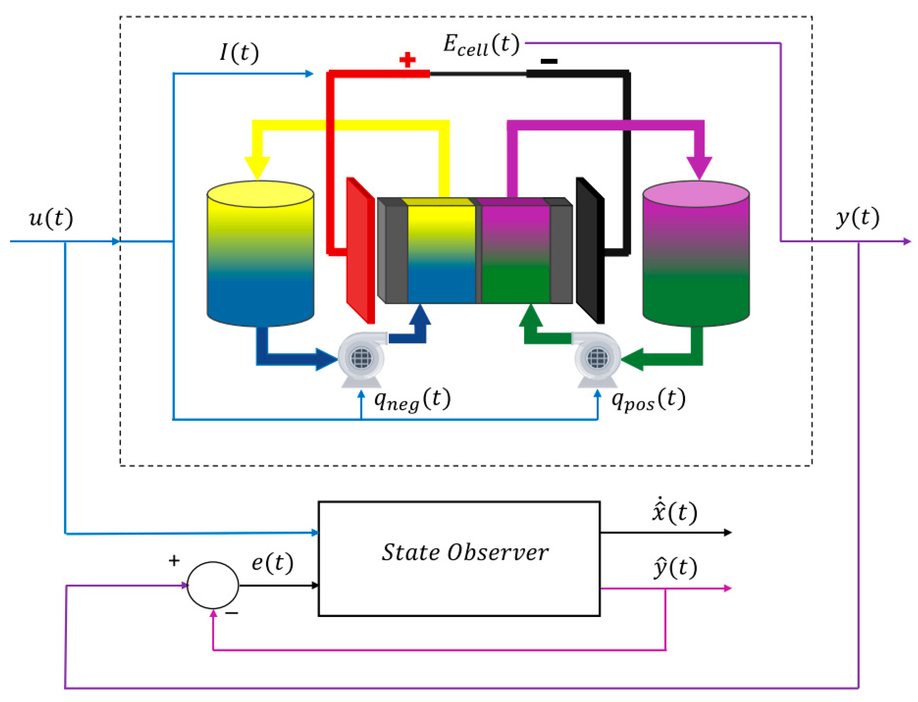
Compared to one-dimensional, two-dimensional, or even three-dimensional multiphysics models, 0D models do not resolve hydrodynamic details or local concentration and potential variations, as illustrated in Figure 11 [78]. However, by incorporating suitably averaged transport and reaction terms, they can effectively capture the essential electrochemical behavior of VRFBs. This allows for a practical trade-off between computational efficiency and engineering applicability. For example, Puleston et al. demonstrated the effectiveness of lumped parameter models in the modeling and estimation of VRFBs for rapid prediction of battery behavior [79]. As shown in Figure 12, their method employed an observer-based strategy to estimate internal system states such as state of charge (SOC) and state of health (SOH). The observer performed state estimation by processing the system’s input and output signals, using a dynamic copy of the model to generate estimated values. A correction term was introduced, which was typically proportional to the difference between the measured output and the estimated output, thereby enhancing the accuracy of the state estimation process. Recently, to enhance the accuracy of SOC predictions, nonlinear lumped concentration models have been developed [80], which differentiate species concentrations across various system components while accounting for associated overpotentials. Building upon these advances, lumped models have been further coupled with higher-dimensional models to more accurately capture membrane crossover phenomena and their impacts on cell voltage, capacity and energy decay, membrane concentration distribution, and electrolyte imbalance. Alejandro Clemente et al., based on the electrochemical assumptions proposed by Skyllas-Kazacos, introduced a hybrid analytical-numerical model integrating a two-dimensional analytical solution for active species concentration, a one-dimensional crossover migration model, and a zero-dimensional numerical model for reactant outlet concentrations [81]. This model was validated against experimental data over 41 charge–discharge cycles (~144 h), demonstrating excellent agreement in voltage, capacity, and energy predictions with an average voltage deviation of only 0.0089 V, and maximum relative errors of 1.34% and 1.63% in capacity and energy, respectively. Moreover, the model successfully reproduces electrolyte imbalance behavior and elucidates the effects of membrane crossover, self-discharge, and side reactions on such imbalance. Subsequent studies have further simplified three-dimensional distributed models into one-dimensional forms, from which lumped model expressions were analytically derived, resulting in lumped parameter models reduced across spatial dimensions. Validation against high-dimensional distributed models under varying current densities confirmed the accuracy of these models. The results indicate that the lumped parameter models can accurately replicate the dynamic behavior of higher-dimensional models while preserving essential physical mechanisms, achieving high predictive consistency [78].

3.2. Microscale Modeling

Microscale modeling focuses on the fundamental physical and electrochemical processes occurring at the electrode–electrolyte interface and within the pore structure of porous electrodes [27,82]. At this scale, models typically consider the coupling of mass transport, charge transfer, electric double-layer structure, and reaction kinetics to elucidate how the microstructure affects overall battery performance [83]. Common approaches include pore-scale and molecular-scale modeling. The former investigates transport and reaction phenomena within porous electrodes by solving the governing equations of charge conservation, mass transport, and reaction kinetics using methods such as the finite element method, finite volume method, or lattice Boltzmann method (LBM), aiming to describe electrolyte diffusion in pore channels and reactant utilization at the solid–liquid interface [26,84]. The latter targets atomic or molecular-level interactions, including vanadium ion diffusion, solvation structures, charge transfer mechanisms, and interfacial reaction pathways, and typically employs molecular dynamics to simulate ion diffusion and solvation shells, density functional theory to evaluate interfacial reaction energy barriers, and Monte Carlo methods for statistical analysis of adsorption behaviors [85]. These microscale modeling techniques offer valuable insights into material-level performance limitations and provide theoretical guidance for optimizing electrode architecture and electrolyte formulation.
In the microscale modeling of VRFBs, the LBM has been widely employed as a powerful simulation approach. As a mesoscopic numerical method, LBM is capable of directly simulating fluid flow and mass transport in complex geometries, such as porous media [83]. As illustrated in Figure 13a, to gain deeper insights into the coupled electrochemical reactions and transport phenomena occurring at the electrode–electrolyte interface and within the porous structure, researchers commonly integrate LBM with electrochemical reaction models at the pore scale. This allows for the investigation of how fiber diameter and porosity influence electrolyte flow, vanadium ion transport, and electrochemical reaction efficiency at the fiber–electrolyte interface [71]. However, traditional porous electrode models typically consist of a limited number of carbon fibers arranged in regular patterns, which significantly deviates from the complex and irregular architecture of actual electrode materials. To overcome this limitation, a pore network modeling (PNM) framework has been developed. PNM abstracts the intricate porous structure into a network composed of pores (nodes) and throats (connections), effectively enabling the simulation of fluid flow and mass transport [86]. As shown in Figure 13b, fiber structures are constructed using image-based generation algorithms, from which pore networks are extracted to capture the fiber arrangement and porosity distribution [87]. This approach facilitates detailed investigations into how multilayer electrode structures affect VRFB performance.
In addition to fiber arrangement and pore distribution, the structural deformation of electrodes under compression is another critical factor influencing battery performance. Microscale modeling serves as an effective tool to explore how compression alters the porous structure and associated transport properties. Commonly, finite element method, pore-scale modeling, and LBM are employed to reconstruct three-dimensional structures of carbon felt electrodes based on XCT scans, followed by meshing to generate realistic geometric models (see Figure 13c). By incorporating fiber–fiber interactions such as contact, friction, compression, and bending, these models allow the simulation of structural deformation under varying compression ratios, thereby establishing quantitative relationships between compression ratios and effective transport properties [88]. For instance, when the compression ratio increases from 0% to 30%, the effective diffusivity of vanadium ions decreases by 15.4% and 24.2% in the in-plane and through-plane directions, respectively; concurrently, electrical conductivity increases by 102.1% and 72.7% in these respective directions. Notably, through-plane diffusivity exhibits higher sensitivity to compression. Additionally, increasing the compression ratios from 0% to 10%, 20%, and 30% results in reductions in liquid permeability in the in-plane direction by 15.7%, 38%, and 47.8%, respectively. To reduce the computational cost associated with microscale simulations, various optimization algorithms and modeling strategies have been proposed. For instance, a general PNM framework independent of specific microstructures and chemical systems has been developed [89]. This model iteratively solves the transport equations within the two half-cells and adopts a network-in-series approach to simulate localized transport phenomena in porous electrodes at reduced computational expense, providing an efficient tool for electrode structure optimization and performance enhancement.

3.3. Multi-Scale Modeling

Multi-scale modeling has emerged as a powerful approach to comprehensively understand and accurately predict battery behavior by coupling models across different spatial and temporal scales. It is designed to overcome the limitations of single-scale models in representing complex multiphysics phenomena. This approach effectively incorporates microscale features, such as electrode pore structure and material transport properties, into macroscale battery models, thereby improving the overall accuracy and applicability of the modeling framework [90]. For example, pore-scale models such as PNM or the LBM are often coupled with two- or three-dimensional continuum models to facilitate information transfer from the pore level to the cell level. In these coupled models, effective transport parameters obtained from the microscale, including diffusion coefficients, specific surface area, and permeability, are embedded into the macroscale models [88,91]. Conversely, boundary conditions and operating parameters at the macroscale, such as current density and flow distribution, influence the microscale reaction behaviors, forming a dynamic and reciprocal feedback loop [27,84].
Yuxin Zuo et al. developed a hierarchical multi-scale model to predict the performance of all-vanadium microfluidic fuel cells. The model establishes an effective linkage across different temporal and spatial scales using the diffusion coefficient as a bridging parameter, while integrating multiple computational methods [92]. At the microscale, molecular dynamics simulations were employed to calculate the diffusion coefficient of vanadium ions in sulfuric acid solution. This microscale result was then used as an input parameter for mesoscale modeling, representing the effective diffusion coefficient in porous carbon electrodes. The obtained values showed strong consistency with the Bruggemann correction. At the macroscale, a two-dimensional steady-state model incorporating an H-shaped flow channel was constructed to simulate the polarization and power density curves of the microfluidic fuel cells, based on parameters derived from lower scales. The simulation results exhibited excellent agreement with experimental data, validating the accuracy and reliability of the proposed multi-scale model. In addition, Md Abdul Hamid et al. proposed a bottom-up multi-scale theoretical framework to investigate the transient mass transport behavior of redox-active species in porous electrodes under time-dependent current conditions [91]. This approach integrates pore-scale transport phenomena into macroscale modeling through the introduction of frequency-dependent transfer functions. Among these, the spectral Sherwood number serves as a generalized extension of the classical film law of mass transfer to transient regimes, enabling the estimation of average interfacial flux driven by local concentration differences. Another transfer function characterizes the acceleration or suppression of solute advection resulting from velocity and concentration gradients at the pore scale. Numerical simulations, based on an idealized porous structure composed of solid cylinders in transverse flow, reveal a frequency-dependent transition in system response from lag-free behavior to a semi-infinite Warburg-type regime. These transfer functions are further incorporated into an upscaled model via volume averaging, allowing accurate prediction of polarization behavior without the need for fitting parameters. The proposed model demonstrates superior performance compared to conventional film law of mass transfer-based approaches in capturing transient electrochemical responses.
In recent years, with the rapid advancement of data-driven methodologies, machine learning has been increasingly integrated into multi-scale modeling frameworks to enhance both predictive accuracy and computational efficiency. In this context, Bao et al. proposed a multi-scale modeling framework that couples deep neural networks with the lattice Boltzmann equation. Based on 128 sets of pore-scale data obtained via quantum Monte Carlo sampling, the framework establishes quantitative correlations between operating parameters (inlet velocity, current density, inlet concentration) and the uniformity of pore-scale surface reactions, characterized by standard deviation and cumulative distribution function [93]. The results demonstrate that this approach improves the prediction accuracy of reaction uniformity by approximately four times compared to traditional multivariate adaptive regression splines models and effectively captures the evolving characteristics of cumulative distribution function. Under the target uniformity condition of σr ≤ 10%, the optimized time-varying inlet velocity strategy ensures that 93% of the discharging period operates at flow rates ≤ 10 mL/min, reducing pump power consumption to 26% of that required by a constant 20 mL/min scheme. Consequently, the overall system efficiency increases to 82%, representing a 6% improvement over conventional strategies. This flexible framework is applicable to a wide range of flow battery chemistries and electrode structure designs, highlighting the great potential of integrating deep neural networks with partial differential equation solvers in multi-scale modeling. Furthermore, to address the prediction of local polarization phenomena, Luo et al. developed a more comprehensive multi-scale modeling framework by integrating deep neural networks, PNM, and three-dimensional continuum models, as illustrated in Figure 14 [94]. Within this framework, the PNM quantitatively evaluates the impact of electrode microstructure on performance, while the cell-scale continuum model focuses on fluid flow and mass transport, independent of microstructural details. The deep neural network serves as a bridging mechanism between the two scales by being trained on local polarization data generated from the pore-scale model and incorporating outputs from the continuum model. This approach not only enhances physical consistency and scalability but also significantly reduces computational complexity.
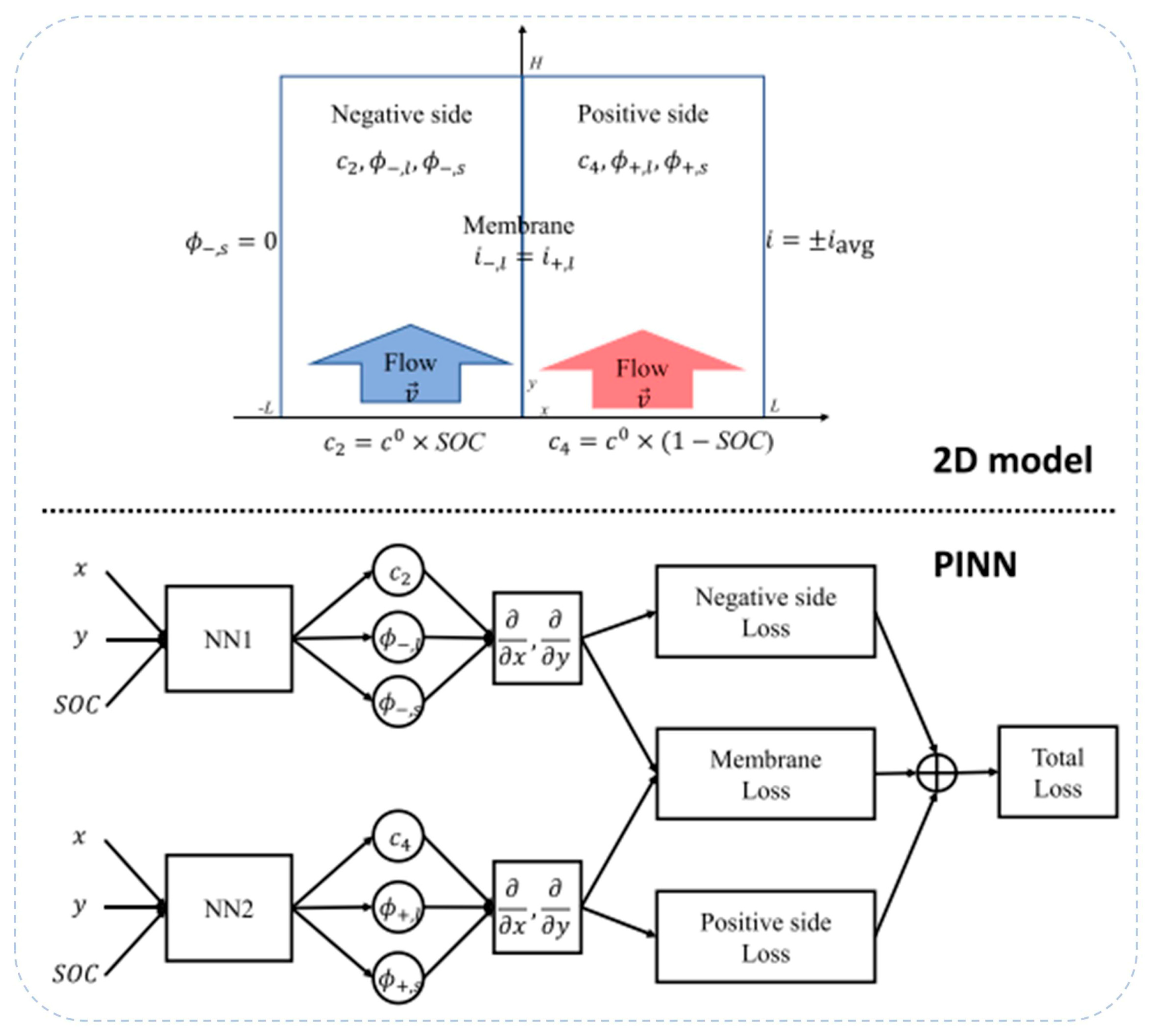
Recent studies have demonstrated the significant potential of physics-informed neural networks (PINNs) in simulating multiphysics processes in redox flow batteries. As illustrated in Figure 15, Chen et al. proposed a fully physics-constrained PINN framework that incorporates six coupled partial differential equations and multiple boundary conditions to capture the electrochemical reactions, mass transport, and fluid dynamics within a vanadium redox flow battery [95]. By employing a self-adaptive weighted loss function, the model effectively balances the governing physical laws with limited observational data. Upon incorporating a small amount of labeled data, the model successfully corrected a persistent bias in the predicted electric potential and accurately reconstructed the battery voltage profile, highlighting the capability of PINNs to dynamically compensate for modeling errors in coupled field simulations. Moreover, in the context of multi-scale fibrous structures, PINNs have been integrated into the Darcy equation framework to infer spatially varying permeability within porous electrodes [96]. Compared to conventional upward-scaling methods, this approach reduces prediction error by over 30% while maintaining good scalability. However, the training of PINNs is susceptible to overfitting, particularly when the loss weights are improperly configured, potentially resulting in excessive data fitting at the expense of partial differential equation residuals or boundary condition accuracy, thereby compromising the model’s long-term extrapolation capability. This limitation is further exacerbated in data-scarce scenarios, where the generalization ability of the model becomes increasingly constrained.

4. Modeling of Other Typical Aqueous Redox Flow Batteries

Over the past five decades, continuous iteration and technological innovation have driven remarkable progress in the development of flow battery systems. Notably, breakthroughs have been achieved in three critical areas: ion-exchange membrane materials, electrolyte formulation optimization, and flow field design within the battery stack [97,98,99,100]. These advancements have collectively propelled the coordinated evolution of multiple flow battery chemistries, including vanadium-based, organic molecule-based, zinc-based, iron-chromium, and hydrogen–bromine systems [101,102,103,104,105,106,107]. With the continued maturation of these chemistries and ongoing breakthroughs in key technologies, a diversified and mutually supportive industrial ecosystem for flow batteries has gradually taken shape. This has not only laid a solid foundation for broader application scenarios but also significantly accelerated the large-scale commercialization of flow battery technologies.
Among these various chemistries, the iron-chromium redox flow battery and the aqueous organic redox flow battery, although they employ different redox couples, share fundamental electrochemical mechanisms and modeling approaches with the VRFB [108,109]. Nevertheless, the modeling of aqueous organic redox flow batteries requires additional considerations, such as adjusting the solution conductivity based on the specific properties of the organic electrolyte, which distinguishes them from VRFBs [110]. In contrast, zinc-based and hydrogen–bromine flow batteries exhibit distinct reaction mechanisms and operational characteristics compared to the conventional VRFB due to phase change. In zinc-based flow batteries, the electrochemical processes involve a solid–liquid phase transition at the negative electrode, where zinc is reversibly deposited and dissolved during charging and discharging [111,112]. This is fundamentally different from the liquid–liquid redox reactions observed in VRFBs. Similarly, hydrogen–bromine flow batteries involve multiphase reactions, including the evolution of gaseous hydrogen and the formation of solid bromine, introducing additional complexity in system behavior and modeling [113,114]. Given these mechanistic distinctions, the modeling strategies for these systems must be adapted to capture the unique physical and electrochemical processes involved. In the following sections, we focus on the reaction principles and recent modeling advances of zinc-based and hydrogen–bromine flow batteries, highlighting the key differences from traditional VRFB systems and discussing the implications for system design and performance optimization.

4.1. Zinc-Based Flow Batteries

Zinc-based flow batteries (ZFBs) are a class of rechargeable electrochemical energy storage systems that employ metallic zinc as the active material at the negative electrode. Based on the redox species used at the positive electrode, ZFBs are commonly classified into several representative systems, including zinc iron (Zn-Fe), zinc nickel (Zn-Ni), and zinc bromine (Zn-Br) flow batteries [115,116,117,118]. Although all these systems share the same fundamental mechanism of zinc deposition and dissolution at the anode, the variation in cathodic redox couples leads to distinct differences in electrochemical behavior, stability, and potential applications. Given the methodological similarities in modeling approaches among the three zinc-based flow battery systems, this work primarily focuses on the zinc–iron flow battery (ZIFB) as a representative case for illustrating the modeling strategies of zinc-based flow batteries.
Among the various ZFBs, the ZIFB has received considerable attention due to its abundant and low-cost materials, environmental friendliness, and system simplicity. Depending on the electrolyte composition, ZIFBs can be divided into acidic and alkaline systems [119,120]. Although the acidic system offers a relatively high theoretical cell voltage, the ferric ions in acidic media are prone to hydrolysis and precipitation, resulting in poor electrolyte stability and limited cycle life [121,122] Consequently, most recent studies and initial commercialization efforts have concentrated on alkaline ZIFB systems.
In addition to the aforementioned advantages, ZIFBs also benefit from the excellent electrochemical properties of zinc, such as fast reaction kinetics and a high overpotential for the hydrogen evolution reaction. Furthermore, the high solubility of zinc salts enables the system to achieve potentially high energy densities. However, the formation of zinc dendrites remains a critical technical challenge. These dendrites can penetrate the ion exchange membrane, resulting in internal short circuits and compromising the overall safety and operational stability of the system.
The typical electrochemical reactions in an alkaline ZIFB are as follows:
Negative electrode: Zn(OH)42− + 2e ⇌ Zn + 4OH (E0 = −1.26 V vs. SHE)
Positive electrode: Fe(CN)64− ⇌ Fe(CN)63− + e (E0 = +0.36 V vs. SHE)
Overall reaction: Zn(OH)42− + 2Fe(CN)64− ⇌ Zn + 2Fe(CN)63− (E0 = 1.62 V)
The electrode potentials involved in the equations are measured under standard conditions, namely, 1 M concentrations of all species, a temperature of 25 °C, and a pressure of 1 atm.
As illustrated in Figure 16, the ZIFB system is configured with an ion exchange membrane that separates the anodic and cathodic compartments. In the alkaline electrolyte at the negative side, zinc exists in the form of Zn(OH)42− and undergoes reversible electrochemical deposition and dissolution during charge and discharge processes. On the positive side, a hexacyanoferrate redox couple (Fe(CN)63−/Fe(CN)64−) serves as the active species, exhibiting excellent electrochemical reversibility and chemical stability. This configuration not only provides a moderate and practical cell voltage, but also eliminates the issue of electrolyte cross-contamination commonly encountered in vanadium redox flow batteries. As a result, the system offers superior safety characteristics and significant cost advantages.
In the numerical modeling of zinc electrodes coupled with three-dimensional porous structures, the electrochemical deposition of metallic zinc within the porous matrix during cycling significantly alters the morphology of the electrode–electrolyte interface and the associated reaction kinetics. As shown in Figure 17, during the charging process, zinc progressively deposits within the pore network, leading to pore blockage and a continuous decrease in local porosity [25,124]. This evolution in microstructure adversely affects mass transport processes and reduces the effective reaction surface area, thereby imposing considerable limitations on the electrode reaction rate and overall battery performance. Therefore, it is essential for any accurate and predictive model to incorporate the time-dependent variation of electrode porosity and structural parameters. Such dynamic considerations are critical for capturing the coupled interactions between electrode morphology, species transport, and electrochemical kinetics throughout the charge–discharge cycles.
During the charging process of the battery, metallic zinc is gradually deposited within the porous electrode, leading to a continuous increase in the solid volume fraction. This process significantly alters the electrode’s microstructure, resulting in a time-dependent evolution of the local porosity. Therefore, to accurately capture the structural changes of the porous electrode during cycling, it is necessary to incorporate a time-dependent porosity function into the model. This relationship can be expressed as [123]
ε t = 1 2 F M W Z n ρ Z n a ( ) I ( )
where, MW and ρ represent the molar mass and density of zinc, respectively. The right-hand side of the equation accounts for the change in electrode volume resulting from the electrochemical transformation of Zn(OH)42− into metallic zinc. In the expression, a(−) denotes the specific surface area of the negative electrode, and I(-) refers to the local reaction current density at the negative electrode.
a a 0 = 1 ( ε p ε ) p
where, a0 represents the initial specific electrochemical surface area, εₚ denotes the volume fraction of the solid zinc product, and p is a geometric factor that characterizes the spatial distribution and surface coverage of zinc deposits within the porous electrode. This factor is typically obtained through experimental measurements or data fitting, and it reflects the impact of different deposition morphologies, such as compact layers or dendritic structures, on the effective electrochemical reaction interface.
This model enables effective simulation and analysis of the ZIFB system. As illustrated in Figure 18, the effects of flow rate, electrode thickness, and electrode porosity within a three-dimensional porous structure were systematically investigated in relation to electrochemical performance. The results indicate that increasing the flow rate, electrode thickness, and porosity all contribute positively to the improvement of battery performance [123]. Based on these findings, an optimized ZIFB configuration was developed, incorporating a high flow rate of 50 mL min−1, an asymmetric electrode design with a negative electrode thickness of 7 mm and a positive electrode thickness of 10 mm, as well as highly porous electrodes with a porosity of 0.98. Under the optimal operating and structural conditions, the electrolyte utilization, coulombic efficiency, and energy efficiency reached 98.62%, 99.18%, and 92.84%, respectively, representing a significant enhancement compared to the unoptimized baseline configuration.
For electrochemically driven solid–liquid phase transitions such as zinc deposition, a widely adopted approach is to embed the Butler–Volmer kinetics into the Allen–Cahn equation, thereby forming a non-equilibrium reaction phase-field model [126]:
ϕ t = L ( f ( ϕ ) ϕ κ 2 ϕ ) + R ( η , ϕ )
The reaction kinetics term is given by:
R ( η , ϕ ) = k 0 h ( ϕ ) [ exp ( α F η R T ) exp ( ( 1 α ) F η R T ) ]
in this model, ϕ denotes the phase-field variable, representing the local phase state, with ϕ = 0 corresponding to the liquid phase and ϕ = 1 to the solid phase. F represents the total free energy of the system, and L is the kinetic mobility coefficient that governs the rate of interface evolution. The term h(ϕ) is an interfacial enhancement function. The local overpotential η serves as the electrochemical driving force for phase transformation, f(ϕ) is the local free energy density that determines the thermodynamic stability of each phase, and κ is the gradient energy coefficient associated with the interfacial energy between different phases.
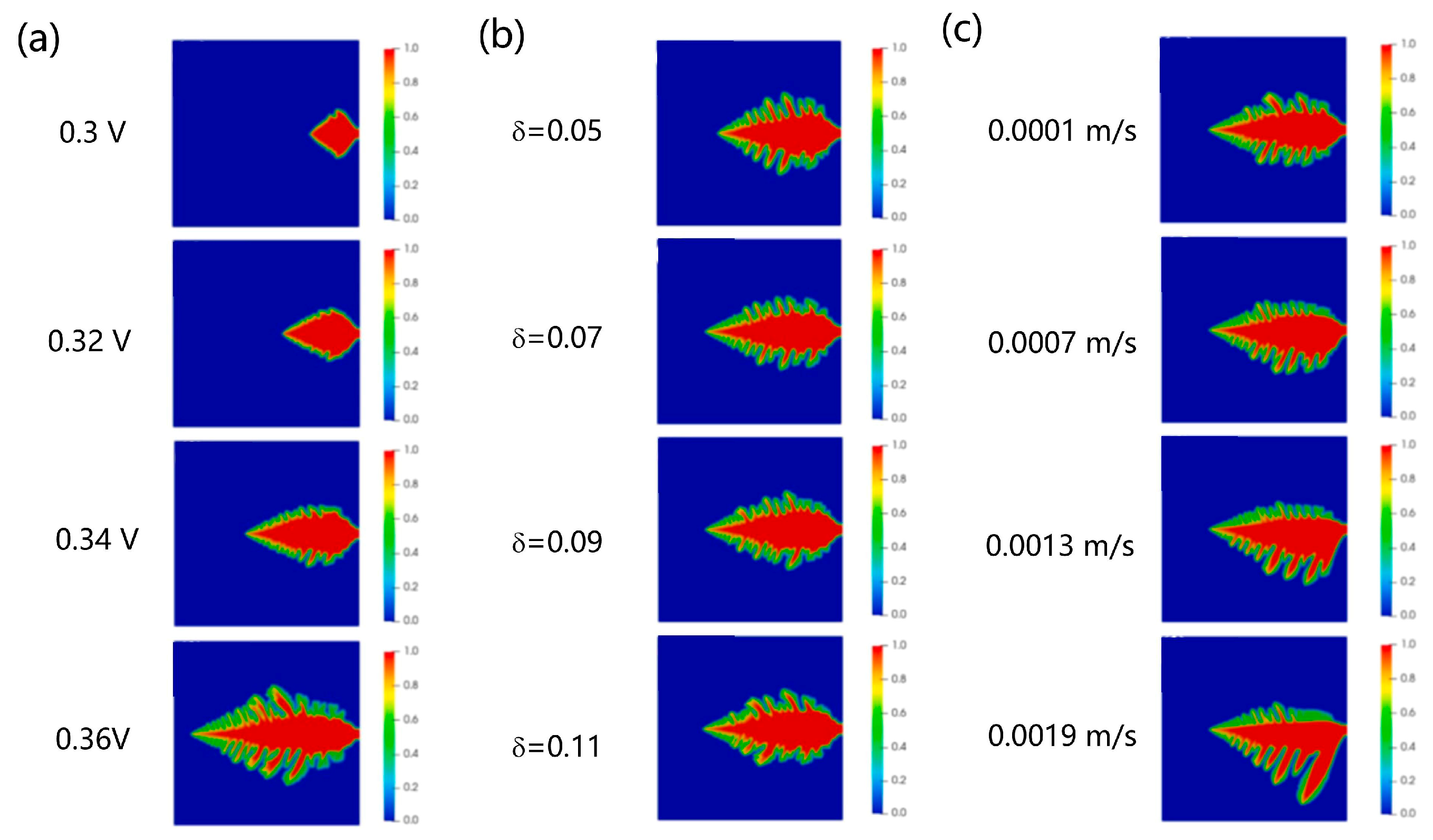
During the zinc deposition process, the formation and evolution of dendrites are influenced by a variety of factors (as illustrated in Figure 19), including electric field distribution, local concentration gradients, nucleation sites, and interfacial perturbations, all of which exhibit significant stochasticity at the microscale [127,128]. Conventional phase-field models, which operate within a deterministic framework, often fail to capture the impact of these subtle disturbances on the evolution of the macroscopic morphology. As a result, neglecting the inherent randomness in dendrite growth may lead to overly smoothed predictions, underestimation of morphological complexity, or the absence of branched structures, thereby compromising the model’s ability to accurately predict extreme scenarios such as dendrite penetration through the separator or sudden short-circuit events.
To enhance the robustness and physical reliability of the model, appropriate stochastic perturbation terms ξ(r,t) should be introduced to capture the uncertainty of initial nucleation sites and the amplification effects of local interfacial disturbances on the growth direction:
ϕ t = L ( f ( ϕ ) ϕ κ 2 ϕ ) + R ( η , ϕ ) + ξ ( r , t )
The introduction of stochasticity not only enhances the diversity of dendritic morphologies in simulations but also promotes the formation of nucleation sites and disordered dendrites, particularly under the influence of higher noise amplitudes [129].
In addition to enhancing performance through modeling, simulation, and structural optimization to meet the demands of commercial applications, ZIFBs continue to face a fundamental limitation in energy density. Their typical energy density remains below 40 Wh L−1, which poses a significant obstacle to their widespread and rapid deployment. As a result, enhancing the energy density has become a major research priority. To address this issue, researchers have proposed a low-cost, high-capacity electrolyte system based on the ferricyanide/ferrocyanide redox couple ([Fe(CN)6]4−/[Fe(CN)6]3−), utilizing a targeted redox reaction with Prussian blue (Fe4[Fe(CN)6]3, PB) for energy storage [130]. This [Fe(CN)6]4−/[Fe(CN)6]3−-PB electrolyte exhibits exceptional capacity retention, with a per-cycle capacity retention rate as high as 99.991%, and delivers an unprecedentedly high volumetric capacity of up to 61.6 Wh L−1.
At present, ZFBs continue to face a range of critical technical challenges, many of which are also common in conventional zinc-based systems. These include the growth of zinc dendrites that may penetrate ion exchange membranes [21,131], zinc passivation in alkaline electrolytes [132,133], and side reactions such as hydrogen evolution [134,135]. These issues significantly compromise the electrochemical stability, coulombic efficiency, and cycle life of the battery, thereby limiting the large-scale deployment and commercialization of zinc-based flow battery technology. Although experimental studies have provided valuable insights into these degradation mechanisms [136,137,138], current numerical modeling efforts remain limited in both scope and sophistication. To advance zinc-based flow battery technologies, developing sophisticated and accurate modeling frameworks remains a pressing priority. These frameworks should enable detailed characterization of the complex interfacial evolution between the electrode and electrolyte, facilitate the prediction of potential failure mechanisms, and support the rational design and operational optimization of high-performance and durable battery systems.

4.2. Hydrogen Bromide Flow Battery

The hydrogen–bromine redox flow battery (HBRFB) employs aqueous HBr solution as the electrolyte carrier for active species [139,140]. At a concentration of 5 mol/L HBr, the theoretical gravimetric energy density of the electrolyte can reach up to 430 Wh L−1. Compared to conventional VRFBs (typically > USD 100/kWh), HBRFBs offer a disruptive cost advantage, with the raw material cost of the electrolyte estimated to be below USD 20/kWh [141].
In this system, gaseous hydrogen and aqueous Br2/HBr solution serve as the active species for the negative and positive electrodes, respectively. The redox reactions during discharge are described as follows:
Negative electrode: 2H+ + 2e ⇌ H2↑ (E = 0 V vs. SHE)
Positive electrode: 2HBr ⇌ Br2 + 2H+ + 2e (E+ = 1.09 V vs. SHE)
Overall reaction: 2HBr ⇌ H2↑ + Br2 (E0 = 1.09 V)
The electrode potentials involved in the equations are measured under standard conditions, namely, 1 M concentrations of all species, a temperature of 25 °C, and a pressure of 1 atm.
The cell structure is shown in Figure 20, the negative electrode involves the redox reaction between H+ and H2, while the positive electrode undergoes the redox conversion between Br and Br2. Compared to conventional VRFBs, this system generates hydrogen gas as a product at the negative electrode, where a phase transition from liquid to gas occurs [142]. As a result, gas–liquid two-phase flow is introduced, leading to significant differences in modeling strategy and operational behavior.
During the modeling process, although the general framework remains similar to that of VRFBs and is governed by mass conservation, species conservation, and charge conservation equations, the presence of two-phase flow at the hydrogen electrode requires that all related physical quantities be evaluated using multiphase flow theory. For example, the density ρ of the gas–liquid mixture is calculated as
ρ = ρ l s + ρ g ( 1 s )
here, l and g denote the liquid and gas phases, respectively, while s represents the volume fraction of liquid occupying the porous space. The velocity of the gas–liquid mixture, v , is given by
v = 1 ρ ( ρ l v l + ρ g v g )
the mass fraction mi of a specific component in the ga-liquid mixture is defined as
m i = 1 ρ [ ρ s m i l + ρ g ( 1 - s ) m i g ]
the relative permeability can be expressed as
k r = k r l = s 4 k r g = ( 1 s ) 4
kinematic viscosity:
υ = ( k r l υ l + k r g υ g ) 1 ,   υ g = μ g ρ g
relative mobility:
λ = λ l = k r l ν l ν λ g = 1 λ l
for the gas–liquid two-phase system at the hydrogen electrode, the species conservation equation can be expressed as:
( γ i ρ m i v ) = ρ g D i g , e f f m i g + m i g m i l j l + S i
γ i = ρ ( λ l m i l + λ g m i g ) s ρ l m i l + ( 1 s ) ρ g m i g
effective diffusion coefficient D i g , e f f of a binary mixture in a porous electrode:
D i g , e f f = ε ( 1 s ) τ ( 1 D i g + 1 D i K ) 1
D i K = 2 3 r p ( 8 R T π M i )
here, M denotes the molar mass, τ is the tortuosity of the porous electrode, rp represents the fiber diameter of the porous structure, R is the universal gas constant, and T is the temperature. Using the standard Butler–Volmer equation, the current density jh of the hydrogen electrode is expressed as follows:
j h = ( 1 s ) 1.5 a h i 0 , h r e f ( C H 2 C H 2 r e f ) 1 / 2 ( e α a , h F R T η h e α c , h F R T η h )
To compare the accuracy between the traditional single-phase model, which ignores gas and liquid two phase transport on the hydrogen electrode side, and the two -phase flow model. As shown in Figure 21a, a comparison of the polarization performance during charge and discharge reveals that the single-phase model predicts superior cell performance [142]. This discrepancy arises because the single-phase model fails to capture the water flooding behavior in the hydrogen catalyst layer and significantly underestimates the electrolyte dehydration effect caused by HBr accumulation, resulting in inaccurate simulation outcomes. Moreover, as illustrated in Figure 21b, the contour plots of HBr concentration in the middle of the hydrogen catalyst layer during discharge further emphasize the divergence between the two models. In particular, the HBr concentration predicted by the single-phase model is approximately 2–3 orders of magnitude lower than that of the two-phase simulation shown in Figure 21c. These findings clearly demonstrate that for HBRFBs involving gas–liquid interactions, the use of a two-phase flow model is both accurate and essential.
Given the superior accuracy of two-phase flow models, they have been widely adopted in the structural optimization of flow batteries. For example, in the modeling of a three-dimensional HBRFB, two electrolyte flow configurations, namely the flow-by and flow-through modes, were investigated through numerical simulation. The model was applied to a full scale cell geometry and successfully validated using experimentally measured polarization curves under both flow configurations [139]. Furthermore, the model accurately reproduced the voltage evolution observed during the discharge process, effectively capturing the transient behavior of the HBRFB system influenced by the bromate and bromide redox reaction. This provides a solid theoretical foundation for understanding performance degradation mechanisms and optimizing the electrochemical reaction pathways [143].
At present, the development of HBRFB still faces several critical challenges [144]. Among them, the high volatility of bromine and its permeability through ion-exchange membranes are recognized as major bottlenecks limiting the widespread application of this technology. The crossover of bromine molecules not only results in the loss of active species but also induces capacity fade and self-discharge, significantly compromising the cycle life and energy efficiency of the battery [145]. To mitigate these issues, current research has largely focused on the optimization of membrane materials to suppress bromine crossover [146,147,148]. A commonly employed strategy is the use of complexing agents to stabilize bromine in the form of complexes, thereby reducing its free-state concentration and lowering its diffusion rate through the membrane [141,149]. However, this approach has certain limitations. For instance, the addition of complexing agents may reduce the conductivity of the electrolyte and negatively affect electrode reaction kinetics. Moreover, residual free bromine in the electrolyte can still diffuse across the membrane, leading to further performance degradation and exacerbated self-discharge. In this context, the development of multiphysics coupled models plays a crucial role in elucidating the complex interactions of mass, momentum, and charge transport within the cell. Through multi-scale modeling, the transport behavior of bromine and its impact on battery performance can be deeply understood [150], while also enabling the optimization of membrane materials, electrode configurations, and operational parameters without relying on extensive experimental efforts. This approach provides a strong theoretical foundation for advancing the practical implementation and commercialization of HBRFB technology.

5. Key Challenges and Future Opportunities

In summary, the key reaction characteristics and modeling approaches of the major flow battery systems discussed in this work under the macroscopic continuum modeling framework are summarized in Table 1. Although various models have been developed to describe the electrochemical reactions and mass transport phenomena involved, significant challenges still remain in the modeling of aqueous flow batteries.
In aqueous redox flow batteries, although various hydrogen evolution reaction suppressants have been developed to mitigate the impact of hydrogen generation [13,151,152], the formation of hydrogen gas remains nearly unavoidable. However, current modeling studies often adopt simplified treatments of related multiphase flow phenomena, making it difficult to accurately capture the effects of HER on reaction kinetics and mass transport processes. To enhance the physical fidelity of these models, future research should focus on the detailed modeling of bubble behavior, particularly by incorporating the dynamic evolution of gas bubbles under realistic operating conditions, thereby enabling a more accurate depiction of the HER-related performance degradation mechanisms. In addition, optimization of existing multiphysics-coupled models still largely relies on single-variable tuning. There is an urgent need to establish multi-factor synergistic optimization frameworks to improve both the predictive accuracy and the engineering relevance of these models.
In addition, the methodologies for assessing ARFB lifespan are still immature. The commonly used charge balance method provides only a coarse estimate of the SOH [10,153], failing to accurately capture the long-term degradation of critical components and the cumulative effects of parasitic reactions. Currently, there is a lack of systematic models and mechanistic understanding that can predict the aging behavior of electrolytes, electrodes, and membranes. Developing comprehensive and fine-grained lifetime prediction frameworks is urgently needed to improve the reliability of ARFBs under extended operation.
Microscale simulations and multi-scale modeling techniques provide powerful tools for gaining an in-depth understanding of the complex transport and reaction mechanisms within flow batteries. The relevant microscale models discussed in this work are summarized in Table 2. Although significant progress has been made in related research, many models still incorporate considerable simplifications during their development, such as neglecting surface adsorption kinetics at the electrode and electrolyte interface and the nonlinear response of electrolyte viscosity to concentration changes. These simplifications, to some extent, limit the models’ ability to accurately represent the real behavior of batteries.
In addition to these general issues, specific flow battery chemistries pose unique modeling and design challenges. In zinc-based flow batteries, the presence of solid–liquid phase change in the negative electrode makes the three-dimensional porosity and its dynamic evolution key focuses for modeling efforts. Meanwhile, the formation mechanism of zinc dendrites urgently requires detailed investigation via microscale and multi-scale models to advance battery performance and longevity. For hydrogen–bromine redox flow batteries, accurate modeling of the gas–liquid two-phase flow in the hydrogen electrode is critical to realistically capture the negative electrode reaction processes. The diffusion and membrane crossover mechanisms of bromine as well as the impact of complexing agents on battery performance are anticipated to be major future research directions. Through comprehensive transport simulations and modeling, it is expected to provide theoretical insights for addressing capacity decay and stability issues thereby promoting performance optimization and practical deployment of hydrogen–bromine redox flow batteries.
In conclusion, while aqueous redox flow battery modeling has made considerable progress in recent years, significant gaps remain in capturing complex multiphase phenomena, accurately predicting battery degradation, and integrating microscale features into system-level simulations. Addressing these challenges through comprehensive, data-driven, and physically realistic modeling approaches will be key to accelerating the practical deployment of ARFBs for large-scale, long-duration energy storage applications.

6. Summary

Flow batteries have established a significant role in the field of electrochemical energy storage due to their inherent safety and flexible system configuration capabilities. Beyond experimental advancements in materials, numerical modeling has increasingly become an essential tool supporting flow battery research. Modeling approaches not only enable in-depth understanding of the complex physical and chemical processes within the battery but also effectively guide structural optimization and performance enhancement, thereby providing a solid theoretical foundation and parameter basis for experimental studies. This review systematically summarizes the recent progress in modeling and simulation of aqueous flow batteries, with a focus on typical systems including vanadium redox flow batteries, zinc-based flow batteries, and hydrogen–bromine redox flow batteries. It comprehensively covers the structural characteristics and reaction mechanisms of these systems and presents a detailed overview of the multiphysics coupling processes involved, such as electrochemical reactions, mass and energy transport mechanisms. Moreover, it systematically categorizes relevant multi-scale modeling strategies and methodologies.
This review systematically summarizes recent advances in the modeling and simulation of aqueous flow batteries, with a focus on representative systems including vanadium redox flow batteries, zinc-based flow batteries, and hydrogen–bromine flow batteries. It provides a comprehensive overview of the structural characteristics and electrochemical mechanisms of these systems, and elaborates on the coupled multiphysics processes involved, including electrochemical reactions, mass transport, and energy transfer. Furthermore, various multi-scale modeling strategies and methodologies are systematically categorized and discussed in detail. Significant progress has been made in the numerical modeling of vanadium redox flow batteries, particularly in capturing electrode reaction kinetics, mass transport behavior, and ion migration through the membrane. In contrast, modeling zinc-based flow batteries necessitates accounting for solid–liquid phase transitions at the anode and the dynamic evolution of the three-dimensional porous structure. For hydrogen–bromine flow batteries, accurately resolving the gas–liquid two-phase flow within the hydrogen electrode is crucial for reliably representing the electrochemical reaction mechanisms. This review also highlights several key challenges in aqueous flow battery modeling, including hydrogen evolution and the difficulty of lifetime prediction. While microscale and multi-scale models offer great promise in revealing the complex internal mechanisms of flow batteries, many still rely on simplifying assumptions that limit their ability to accurately reflect real-world behavior. Looking ahead, future research should focus on improving model formulations to simultaneously enhance computational efficiency and physical accuracy. Moreover, stronger integration between modeling and experimental validation is needed to improve model reliability and broaden the practical applicability of modeling approaches in system design, optimization, and control of flow batteries.

Author Contributions

Conceptualization, Y.L. and Y.H.; methodology, Y.L. and Y.H.; investigation, Y.L. and Y.H.; writing—original draft preparation, Y.L.; writing—review and editing, Y.H. All authors have read and agreed to the published version of the manuscript.

Funding

This research received no external funding.

Conflicts of Interest

The authors declare that they have no known competing financial interests or personal relationships that could have appeared to influence the work reported in this paper.

Abbreviations

The following abbreviations are used in this manuscript:
ARFBaqueous redox flow battery
HBRFBhydrogen–bromine redox flow battery
LBMlattice Boltzmann methods
PNMpore network modeling
PINNsphysics-informed neural networks
SOCstate of charge
SOHstate of health
VRFBall-vanadium redox flow battery
ZFBzinc-based flow battery
ZIFBzinc–iron flow battery

References

  1. Hou, Z.; Chen, X.; Liu, J.; Huang, Z.; Chen, Y.; Zhou, M.; Liu, W.; Zhou, H. Towards a High Efficiency and Low-Cost Aqueous Redox Flow Battery: A Short Review. J. Power Sources 2024, 601, 234242. [Google Scholar] [CrossRef]
  2. Ahmad, A.; Aldawood, T.A.; Mansha, M.; Ali, S.; Tahir, M.N.; Khan, M.; Khan, I.A.; Khan, S.A. Optimized and Cost-Effective Elemental-Sulfur Sodium Polysulfide/Sodium Bromide Aqueous Electrolytes for Redox Flow Batteries. J. Power Sources 2024, 614, 235013. [Google Scholar] [CrossRef]
  3. Park, G.; Jeong, H.; Lee, W.; Han, J.W.; Chang, D.R.; Kwon, Y. Scaled-up Aqueous Redox Flow Battery Using Anthraquinone Negalyte and Vanadium Posilyte with Inorganic Additive. Appl. Energy 2024, 353, 122171. [Google Scholar] [CrossRef]
  4. Xi, D.; Alfaraidi, A.M.; Gao, J.; Cochard, T.; Faria, L.C.I.; Yang, Z.; George, T.Y.; Wang, T.; Gordon, R.G.; Liu, R.Y.; et al. Mild PH-Decoupling Aqueous Flow Battery with Practical PH Recovery. Nat. Energy 2024, 9, 479–490. [Google Scholar] [CrossRef]
  5. Belongia, S.; Wang, X.; Zhang, X. Progresses and Perspectives of All-Iron Aqueous Redox Flow Batteries. Adv. Funct. Mater. 2024, 34, 2302077. [Google Scholar] [CrossRef]
  6. Wu, J.; Nie, R.; Yu, L.; Nie, Y.; Zhao, Y.; Liu, L.; Xi, J. Next-Generation Ultrathin Lightweight Electrode for PH-Universal Aqueous Flow Batteries. Small 2024, 20, e2405643. [Google Scholar] [CrossRef] [PubMed]
  7. Zhang, M.; Xiao, J.; Tang, W.; He, Y.; Tan, P.; Haranczyk, M.; Wang, D.Y. A Novel Benchmarking Approach to Assess Fire Safety of Liquid Electrolytes in Lithium-Ion Batteries. Adv. Energy Mater. 2024, 14, 2401241. [Google Scholar] [CrossRef]
  8. He, Y.; Cui, Y.; Yu, J.; Shang, W.; Tan, P. Advancing Flow Batteries: High Energy Density and Ultra-Fast Charging via Room-Temperature Liquid Metal. Adv. Energy Mater. 2024, 15, 2405066. [Google Scholar] [CrossRef]
  9. Yuan, X.Z.; Song, C.; Platt, A.; Zhao, N.; Wang, H.; Li, H.; Fatih, K.; Jang, D. A Review of All-Vanadium Redox Flow Battery Durability: Degradation Mechanisms and Mitigation Strategies. Int. J. Energy Res. 2019, 43, 6599–6638. [Google Scholar] [CrossRef]
  10. Wang, Y.; Mu, A.; Wang, W.; Yang, B.; Wang, J. A Review of Capacity Decay Studies of All-Vanadium Redox Flow Batteries: Mechanism and State Estimation. ChemSusChem 2024, 17, e202301787. [Google Scholar] [CrossRef]
  11. Michel Myures, X.; Suresh, S.; Arthanareeswaran, G. Construction of Thermal, Chemical and Mechanically Stable Ion Exchange Membranes with Improved Ion Selectivity for Vanadium Redox Flow Batteries Applications. J. Power Sources 2024, 591, 233818. [Google Scholar] [CrossRef]
  12. He, Y.; Shang, W.; Ni, M.; Huang, Y.; Zhao, H.; Tan, P. In-Situ Observation of the Gas Evolution Process on the Air Electrode of Zn-Air Batteries during Charging. Chem. Eng. J. 2022, 427, 130862. [Google Scholar] [CrossRef]
  13. Muralidharan, V.; Jayasubramaniyan, S.; Lee, H.W. Surpassing Water-Splitting Potential in Aqueous Redox Flow Batteries: Insights from Kinetics and Thermodynamics. EES Catal. 2024, 2, 522–544. [Google Scholar] [CrossRef]
  14. Chace, W.S.; Tiano, S.M.; Arruda, T.M.; Lawton, J.S. Effects of State of Charge on the Physical Characteristics of V(IV)/V(V) Electrolytes and Membrane for the All Vanadium Flow Battery. Batteries 2020, 6, 49. [Google Scholar] [CrossRef]
  15. Jing, M.; Wei, Z.; Su, W.; He, H.; Fan, X.; Qin, Y.; Liu, J.; Yan, C. Improved Electrochemical Performance for Vanadium Flow Battery by Optimizing the Concentration of the Electrolyte. J. Power Sources 2016, 324, 215–223. [Google Scholar] [CrossRef]
  16. Wei, Z.; Qu, G.; Huang, Z.; Wang, Y.; Li, D.; Yang, X.; Zhang, S.; Chen, A.; Wang, Y.; Hong, H.; et al. Gradient Distribution of Zincophilic Sites for Stable Aqueous Zinc-Based Flow Batteries with High Capacity. Adv. Mater. 2024, 36, e2414388. [Google Scholar] [CrossRef]
  17. Zou, W.; Jung, H.; Jung, S. Modeling and Performance Optimization of Vanadium Redox Flow Batteries. J. Energy Storage 2025, 121, 116601. [Google Scholar] [CrossRef]
  18. Seepana, M.M.; Samudrala, S.; Suresh, P.V.; Vooradi, R. Unit Cell Modelling and Simulation of All Vanadium Redox Flow Battery. Chem. Prod. Process Model. 2018, 13, 1–11. [Google Scholar] [CrossRef]
  19. Al-Fetlawi, H.; Shah, A.A.; Walsh, F.C. Non-Isothermal Modelling of the All-Vanadium Redox Flow Battery. Electrochim. Acta 2009, 55, 78–89. [Google Scholar] [CrossRef]
  20. Al-Fetlawi, H.; Shah, A.A.; Walsh, F.C. Modelling the Effects of Oxygen Evolution in the All-Vanadium Redox Flow Battery. Electrochim. Acta 2010, 55, 3192–3205. [Google Scholar] [CrossRef]
  21. Jiang, H.J.; Underwood, T.C.; Bell, J.G.; Ranjan, S.; Sasselov, D.; Whitesides, G.M. Mimicking Lighting-Induced Electrochemistry on the Early Earth. Proc. Natl. Acad. Sci. USA 2024, 121, e2400819121. [Google Scholar] [CrossRef] [PubMed]
  22. Sun, Z.W.; Duan, Z.N.; Bai, J.Q.; Wang, Y. Numerical Study of the Performance of All Vanadium Redox Flow Battery by Changing the Cell Structure. J. Energy Storage 2020, 29, 101370. [Google Scholar] [CrossRef]
  23. Lei, Y.; Zhang, B.W.; Bai, B.F.; Zhao, T.S. A Transient Electrochemical Model Incorporating the Donnan Effect for All-Vanadium Redox Flow Batteries. J. Power Sources 2015, 299, 202–211. [Google Scholar] [CrossRef]
  24. Esan, O.C.; Shi, X.; Pan, Z.; Huo, X.; An, L.; Zhao, T.S. Modeling and Simulation of Flow Batteries. Adv. Energy Mater. 2020, 10, 2000758. [Google Scholar] [CrossRef]
  25. Yuan, Z.; Yin, Y.; Xie, C.; Zhang, H.; Yao, Y.; Li, X. Advanced Materials for Zinc-Based Flow Battery: Development and Challenge. Adv. Mater. 2019, 31, e1902025. [Google Scholar] [CrossRef]
  26. Shi, X.; Wu, Q. Recent Understanding on Pore Scale Mass Transfer Phenomena of Flow Batteries: Theoretical Simulation and Experimental Visualization. Curr. Opin. Electrochem. 2025, 49, 101603. [Google Scholar] [CrossRef]
  27. Chakrabarti, B.K.; Kalamaras, E.; Singh, A.K.; Bertei, A.; Rubio-Garcia, J.; Yufit, V.; Tenny, K.M.; Wu, B.; Tariq, F.; Hajimolana, Y.S.; et al. Modelling of Redox Flow Battery Electrode Processes at a Range of Length Scales: A Review. Sustain. Energy Fuels 2020, 4, 5433–5468. [Google Scholar] [CrossRef]
  28. Prifti, H.; Parasuraman, A.; Winardi, S.; Lim, T.M.; Skyllas-Kazacos, M. Membranes for Redox Flow Battery Applications. Membranes 2012, 2, 275–306. [Google Scholar] [CrossRef]
  29. Yang, T.F.; Chen, Y.K.; Lin, C.Y.; Yan, W.M.; Rashidi, S. Effects of Flow Field Designs on Performance Characteristics of Vanadium Redox Flow Battery. J. Taiwan Inst. Chem. Eng. 2025, 171, 106043. [Google Scholar] [CrossRef]
  30. Xie, X.; Liu, Y.; Huang, Z.; He, Z.; Liu, Y.; Huang, Q.; Guo, Z. Numerical Analysis of the Design Optimization Obstruction to Guide Electrolyte Flow in Vanadium Flow Batteries. J. Energy Storage 2024, 101, 113802. [Google Scholar] [CrossRef]
  31. Sun, P.; Zhang, R.; Zhou, H.; Ma, Q.; Zhang, W.; Su, H.; Yang, W.; Xu, Q. Effect of Ultrasonic Field on the Performance of an Iron-Vanadium Flow Battery with Non-Aqueous Deep Eutectic Solvent Electrolyte. Int. J. Energy Res. 2022, 46, 17616–17629. [Google Scholar] [CrossRef]
  32. Duan, Z.N.; Zhang, G.B.; Zhang, J.F.; Qu, Z.G. Experimental Investigation on the Performance Characteristics of Flow Fields in Redox Flow Batteries Under Various Electrode Parameters. Front. Therm. Eng. 2022, 2, 931160. [Google Scholar] [CrossRef]
  33. Shao, M.; Zhang, B. A 2D Thermal Model of Stacked Vanadium Redox Flow Batteries for Efficient Thermal Management. Energy Technol. 2024, 12, 2300873. [Google Scholar] [CrossRef]
  34. Yu, Z.; Jia, X.; Cai, Y.; Su, R.; Zhu, Q.; Zhao, T.; Jiang, H. Electrolyte Engineering for Efficient and Stable Vanadium Redox Flow Batteries. Energy Storage Mater. 2024, 69, 103404. [Google Scholar] [CrossRef]
  35. Puleston, T.; Trovò, A.; Marini, G.; Serra, M.; Costa-Castelló, R.; Guarnieri, M. Design and Experimental Validation of an Optimal Remixing Procedure for Vanadium Flow Batteries Affected by Faradaic Imbalance. J. Power Sources 2024, 624, 235487. [Google Scholar] [CrossRef]
  36. Forner-Cuenca, A.; Brushett, F.R. Engineering Porous Electrodes for Next-Generation Redox Flow Batteries: Recent Progress and Opportunities. Curr. Opin. Electrochem. 2019, 18, 113–122. [Google Scholar] [CrossRef]
  37. Hu, H.; Han, M.; Liu, J.; Zheng, K.; Zou, Z.; Mu, Y.; Yu, F.; Li, W.; Wei, L.; Zeng, L.; et al. Strategies for Improving the Design of Porous Fiber Felt Electrodes for All-Vanadium Redox Flow Batteries from Macro and Micro Perspectives. Energy Environ. Sci. 2025, 18, 3085–3119. [Google Scholar] [CrossRef]
  38. Wang, L.; Zhao, Y.; Lin, D.; Wang, Q.; Liu, C.; Chu, P.; Leung, P. Electrospun Carbon Nanofiber Composite Electrode with Gradient Porous Structure for Rapid Ion Transport in an All-Vanadium Redox Flow Battery. Energy Technol. 2024, 12, 2400825. [Google Scholar] [CrossRef]
  39. Wang, P.; Zhao, Y.; Ban, Y.; Zheng, M. A Review of Porous Electrode Structural Parameters and Optimization for Redox Flow Batteries. J. Energy Storage 2024, 97, 112859. [Google Scholar] [CrossRef]
  40. Tai, Z.; Hanawa, K.; Ju, D.; Luo, W.; Lyu, R.; Ishikawa, K.; Sato, S. Effects of Carbon Fiber Compression Ratio and Electrolyte Flow Rate on the Electrochemical Performance of Vanadium Redox Batteries. J. Chem. 2021, 1, 6646256. [Google Scholar] [CrossRef]
  41. Zheng, Y.; Qu, D.; Yang, F.; Chen, D. Study on Performance Improvement of Vanadium Redox Flow Batteries Focused on Electrode Fabrication Parameters and Compression Strategies. J. Energy Storage 2025, 109, 115142. [Google Scholar] [CrossRef]
  42. Wolf, A.; Noack, J.; Krause, M.J.; Nirschl, H. Enhancing Flow Batteries: Topology Optimization of Electrode Porosity and Shape Optimization of Cell Design. Energy Technol. 2024, 12, 2400244. [Google Scholar] [CrossRef]
  43. Muñoz-Perales, V.; van der Heijden, M.; de Haas, V.; Olinga, J.; Vera, M.; Forner-Cuenca, A. Understanding the Role of Electrode Thickness on Redox Flow Cell Performance. ChemElectroChem 2024, 11, e202300380. [Google Scholar] [CrossRef]
  44. He, Q.; Li, Z.; Bello, I.T.; Xu, Q.; Xia, L.; Wang, C.; Zhao, S.; Zhao, T.; Ni, M. A Comprehensive Modelling Study of All Vanadium Redox Flow Battery: Revealing the Combined Effects of Electrode Structure and Surface Property. J. Energy Storage 2023, 66, 107427. [Google Scholar] [CrossRef]
  45. Gundlapalli, R.; Jayanti, S. Effect of Electrode Compression and Operating Parameters on the Performance of Large Vanadium Redox Flow Battery Cells. J. Power Sources 2019, 427, 231–242. [Google Scholar] [CrossRef]
  46. Kim, M.; Yoo, H.; Lee, G.; Choi, J. Enhanced VRB Electrochemical Performance Using Tungsten as an Electrolyte Additive. Electrochim. Acta 2017, 246, 190–196. [Google Scholar] [CrossRef]
  47. Devi, N.; Singh, P.; Chen, Y.S. Binder-Free CNT-Modified Excellent Electrodes for All-Vanadium Redox Flow Batteries. Nanomaterials 2024, 14, 767. [Google Scholar] [CrossRef]
  48. Zhang, B.W.; Lei, Y.; Bai, B.F.; Zhao, T.S. A Two-Dimensional Model for the Design of Flow Fields in Vanadium Redox Flow Batteries. Int. J. Heat Mass Transf. 2019, 135, 460–469. [Google Scholar] [CrossRef]
  49. Kumar, S.; Jayanti, S. Effect of Flow Field on the Performance of an All-Vanadium Redox Flow Battery. J. Power Sources 2016, 307, 782–787. [Google Scholar] [CrossRef]
  50. Li, J.; Li, X.; El Sawy, E.; Maslovara, S.; Yasri, N.; Birss, V.; Roberts, E.P.L. Investigation of the Impact of the Flow Mode in All-Vanadium-Redox-Flow Battery Using Macroporous and Mesoporous Carbon Electrodes. Mater. Today Commun. 2024, 40, 109773. [Google Scholar] [CrossRef]
  51. Wang, Y.; Li, M.; Hao, L. Three-Dimensional Modeling Study of All-Vanadium Redox Flow Batteries with the Serpentine and Interdigitated Flow Fields. J. Electroanal. Chem. 2022, 918, 116460. [Google Scholar] [CrossRef]
  52. Messaggi, M.; Canzi, P.; Mereu, R.; Baricci, A.; Inzoli, F.; Casalegno, A.; Zago, M. Analysis of Flow Field Design on Vanadium Redox Flow Battery Performance: Development of 3D Computational Fluid Dynamic Model and Experimental Validation. Appl. Energy 2018, 228, 1057–1070. [Google Scholar] [CrossRef]
  53. Perez, N. Mass Transport. In Materials Science: Theory and Engineering; Springer Nature: Cham, Switzerland, 2024; pp. 265–301. ISBN 978-3-031-57152-7. [Google Scholar]
  54. Zago, M.; Casalegno, A. Physically-Based Impedance Modeling of the Negative Electrode in All-Vanadium Redox Flow Batteries: Insight into Mass Transport Issues. Electrochim. Acta 2017, 248, 505–517. [Google Scholar] [CrossRef]
  55. Yin, C.; Gao, Y.; Guo, S.; Tang, H. A Coupled Three Dimensional Model of Vanadium Redox Flow Battery for Flow Field Designs. Energy 2014, 74, 886–895. [Google Scholar] [CrossRef]
  56. Lala, A.M.S.; El-Sayed, N.A.A. Controls of Pore Throat Radius Distribution on Permeability. J. Pet. Sci. Eng. 2017, 157, 941–950. [Google Scholar] [CrossRef]
  57. Khazaeli, A.; Vatani, A.; Tahouni, N.; Panjeshahi, M.H. Numerical Investigation and Thermodynamic Analysis of the Effect of Electrolyte Flow Rate on Performance of All Vanadium Redox Flow Batteries. J. Power Sources 2015, 293, 599–612. [Google Scholar] [CrossRef]
  58. You, D.; Zhang, H.; Chen, J. A Simple Model for the Vanadium Redox Battery. Electrochim. Acta 2009, 54, 6827–6836. [Google Scholar] [CrossRef]
  59. Krowne, C.M. Nernst Equations and Concentration Chemical Reaction Overpotentials for VRFB Operation. J. Electrochem. Soc. 2023, 170, 100534. [Google Scholar] [CrossRef]
  60. Mai, Z.; Zhang, H.; Zhang, H.; Xu, W.; Wei, W.; Na, H.; Li, X. Anion-Conductive Membranes with Ultralow Vanadium Permeability and Excellent Performance in Vanadium Flow Batteries. ChemSusChem 2013, 6, 328–335. [Google Scholar] [CrossRef] [PubMed]
  61. Monteiro, R.; Leirós, J.; Boaventura, M.; Mendes, A. Insights into All-Vanadium Redox Flow Battery: A Case Study on Components and Operational Conditions. Electrochim. Acta 2018, 267, 80–93. [Google Scholar] [CrossRef]
  62. Yang, X.G.; Ye, Q.; Cheng, P.; Zhao, T.S. Effects of the Electric Field on Ion Crossover in Vanadium Redox Flow Batteries. Appl. Energy 2015, 145, 306–319. [Google Scholar] [CrossRef]
  63. Knehr, K.W.; Kumbur, E.C. Role of Convection and Related Effects on Species Crossover and Capacity Loss in Vanadium Redox Flow Batteries. Electrochem. Commun. 2012, 23, 76–79. [Google Scholar] [CrossRef]
  64. Hao, L.; Wang, Y.; He, Y. Modeling of Ion Crossover in an All-Vanadium Redox Flow Battery with the Interfacial Effect at Membrane/Electrode Interfaces. J. Electrochem. Soc. 2019, 166, A1310–A1322. [Google Scholar] [CrossRef]
  65. Lei, Y.; Zhang, B.W.; Zhang, Z.H.; Bai, B.F.; Zhao, T.S. An Improved Model of Ion Selective Adsorption in Membrane and Its Application in Vanadium Redox Flow Batteries. Appl. Energy 2018, 215, 591–601. [Google Scholar] [CrossRef]
  66. Xiong, R.; Xiong, B.; Zhang, Q.; Shi, S.; Su, Y.; Zhang, D. Capacity Fading Model of Vanadium Redox Flow Battery Considering Water Molecules Migration. Int. J. Green Energy 2022, 19, 1613–1622. [Google Scholar] [CrossRef]
  67. Sukkar, T.; Skyllas-Kazacos, M. Water Transfer Behaviour across Cation Exchange Membranes in the Vanadium Redox Battery. J. Memb. Sci. 2003, 222, 235–247. [Google Scholar] [CrossRef]
  68. Shin, J.; Jeong, B.; Chinannai, M.F.; Ju, H. Mitigation of Water and Electrolyte Imbalance in All-Vanadium Redox Flow Batteries. Electrochim. Acta 2021, 390, 138858. [Google Scholar] [CrossRef]
  69. Oh, K.; Moazzam, M.; Gwak, G.; Ju, H. Water Crossover Phenomena in All-Vanadium Redox Flow Batteries. Electrochim. Acta 2019, 297, 101–111. [Google Scholar] [CrossRef]
  70. Bromberger, K.; Kaunert, J.; Smolinka, T. A Model for All-Vanadium Redox Flow Batteries: Introducing Electrode-Compression Effects on Voltage Losses and Hydraulics. Energy Technol. 2014, 2, 64–76. [Google Scholar] [CrossRef]
  71. Chen, L.; He, Y.L.; Tao, W.Q.; Zelenay, P.; Mukundan, R.; Kang, Q. Pore-Scale Study of Multiphase Reactive Transport in Fibrous Electrodes of Vanadium Redox Flow Batteries. Electrochim. Acta 2017, 248, 425–439. [Google Scholar] [CrossRef]
  72. Delgado, N.M.; Monteiro, R.; Abdollahzadeh, M.; Ribeirinha, P.; Bentien, A.; Mendes, A. 2D-Dynamic Phenomenological Modelling of Vanadium Redox Flow Batteries—Analysis of the Mass Transport Related Overpotentials. J. Power Sources 2020, 480, 229142. [Google Scholar] [CrossRef]
  73. Li, Y.; Sun, L.; Cao, L.; Bao, J.; Skyllas-Kazacos, M. Dynamic Model Based Membrane Permeability Estimation for Online SOC Imbalances Monitoring of Vanadium Redox Flow Batteries. J. Energy Storage 2021, 39, 102688. [Google Scholar] [CrossRef]
  74. Barton, J.L.; Brushett, F.R. A One-Dimensional Stack Model for Redox Flow Battery Analysis and Operation. Batteries 2019, 5, 25. [Google Scholar] [CrossRef]
  75. Zhong, L.; Chu, F. A Novel Biomimetic Lung-Shaped Flow Field for All-Vanadium Redox Flow Battery. Sustainability 2023, 15, 13613. [Google Scholar] [CrossRef]
  76. Lee, S.B.; Mitra, K.; Pratt, H.D.; Anderson, T.M.; Ramadesigan, V.; Chalamala, B.R.; Subramanian, V.R. Open Data, Models, and Codes for Vanadium Redox Batch Cell Systems: A Systems Approach Using Zero-Dimensional Models. J. Electrochem. Energy Convers. Storage 2019, 17, 011008. [Google Scholar] [CrossRef]
  77. Pugach, M.; Kondratenko, M.; Briola, S.; Bischi, A. Zero Dimensional Dynamic Model of Vanadium Redox Flow Battery Cell Incorporating All Modes of Vanadium Ions Crossover. Appl. Energy 2018, 226, 560–569. [Google Scholar] [CrossRef]
  78. Pathak, A.; Kumar Sharma, A.; Kumar Gupta, A. Systematic Lumped Modeling of All-Vanadium Redox Flow Batteries. J. Electrochem. Soc. 2022, 169, 100533. [Google Scholar] [CrossRef]
  79. Puleston, T.; Clemente, A.; Costa-Castelló, R.; Serra, M. Modelling and Estimation of Vanadium Redox Flow Batteries: A Review. Batteries 2022, 8, 121. [Google Scholar] [CrossRef]
  80. Clemente, A.; Montiel, M.; Barreras, F.; Lozano, A.; Costa-Castello, R. Vanadium Redox Flow Battery State of Charge Estimation Using a Concentration Model and a Sliding Mode Observer. IEEE Access 2021, 9, 72368–72376. [Google Scholar] [CrossRef]
  81. Chen, Y.; Bao, J.; Xu, Z.; Gao, P.; Yan, L.; Kim, S.; Wang, W. A Hybrid Analytical and Numerical Model for Cross-over and Performance Decay in a Unit Cell Vanadium Redox Flow Battery. J. Power Sources 2023, 578, 233210. [Google Scholar] [CrossRef]
  82. Xu, Q.; Zhao, T.S. Fundamental Models for Flow Batteries. Prog. Energy Combust. Sci. 2015, 49, 40–58. [Google Scholar] [CrossRef]
  83. Qiu, G.; Joshi, A.S.; Dennison, C.R.; Knehr, K.W.; Kumbur, E.C.; Sun, Y. 3-D Pore-Scale Resolved Model for Coupled Species/Charge/Fluid Transport in a Vanadium Redox Flow Battery. Electrochim. Acta 2012, 64, 46–64. [Google Scholar] [CrossRef]
  84. Wlodarczyk, J.K.; Schärer, R.P.; Friedrich, K.A.; Schumacher, J.O. Upscaling of Reactive Mass Transport through Porous Electrodes in Aqueous Flow Batteries. J. Electrochem. Soc. 2024, 171, 020544. [Google Scholar] [CrossRef]
  85. Guo, A.; Zhang, P.; Ma, Y.; Yuan, S. Molecular Dynamics Simulation of the Electrochemical Impact of Aminomethanesulfonic Acid on VO2+ in Vanadium Flow Batteries. Mater. Today Chem. 2025, 47, 102815. [Google Scholar] [CrossRef]
  86. Fu, Y.; Bao, J.; Zeng, C.; Chen, Y.; Xu, Z.; Kim, S.; Wang, W. A Three-Dimensional Pore-Scale Model for Redox Flow Battery Electrode Design Analysis. J. Power Sources 2023, 556, 232329. [Google Scholar] [CrossRef]
  87. Misaghian, N.; Sadeghi, M.A.; Lee, K.M.; Roberts, E.P.L.; Gostick, J.T. Utilizing Pore Network Modeling for Performance Analysis of Multi-Layer Electrodes in Vanadium Redox Flow Batteries. J. Electrochem. Soc. 2023, 170, 070520. [Google Scholar] [CrossRef]
  88. Xiao, L.; Luo, M.; Zhu, L.; Duan, K.; Bevilacqua, N.; Eifert, L.; Zeis, R.; Sui, P.-C. Pore-Scale Characterization and Simulation of Porous Electrode Material for Vanadium Redox Flow Battery: Effects of Compression on Transport Properties. J. Electrochem. Soc. 2020, 167, 110545. [Google Scholar] [CrossRef]
  89. van der Heijden, M.; van Gorp, R.; Sadeghi, M.A.; Gostick, J.; Forner-Cuenca, A. Assessing the Versatility and Robustness of Pore Network Modeling to Simulate Redox Flow Battery Electrode Performance. J. Electrochem. Soc. 2022, 169, 040505. [Google Scholar] [CrossRef]
  90. Pan, S.; Fang, W.; Yan, J.; Zhang, S.; Zhang, H. Multiscale Coupled Electron-Ion Transport in Semi-Solid Lithium Flow Batteries. Energy Environ. Sci. 2025, 18, 5868–5896. [Google Scholar] [CrossRef]
  91. Hamid, M.A.; Smith, K.C. A Bottom-up, Multi-Scale Theory for Transient Mass Transport of Redox-Active Species through Porous Electrodes beyond the Pseudo-Steady Limit. J. Power Sources 2023, 565, 232756. [Google Scholar] [CrossRef]
  92. Yu, Y.; Zuo, Y.; Zuo, C.; Liu, X.; Liu, Z. A Hierarchical Multiscale Model for Microfluidic Fuel Cells with Porous Electrodes. Electrochim. Acta 2014, 116, 237–243. [Google Scholar] [CrossRef]
  93. Bao, J.; Murugesan, V.; Kamp, C.J.; Shao, Y.; Yan, L.; Wang, W. Machine Learning Coupled Multi-Scale Modeling for Redox Flow Batteries. Adv. Theory Simul. 2020, 3, 1900167. [Google Scholar] [CrossRef]
  94. Luo, Y.; Lv, W.; Zheng, M. A Multi-Scale Model for Local Polarization Prediction in Flow Batteries Based on Deep Neural Network. J. Energy Storage 2023, 68, 107842. [Google Scholar] [CrossRef]
  95. Chen, W.; Fu, Y.; Stinis, P. Physics-Informed Machine Learning of Redox Flow Battery Based on a Two-Dimensional Unit Cell Model. J. Power Sources 2023, 584, 233548. [Google Scholar] [CrossRef]
  96. Korolev, D.; Schmidt, T.; Natarajan, D.K.; Cassola, S.; May, D.; Duhovic, M.; Hintermüller, M. Hybrid Machine Learning Based Scale Bridging Framework for Permeability Prediction of Fibrous Structures. arXiv 2025, arXiv:2502.05044. [Google Scholar]
  97. Bukola, S.; Li, Z.; Zack, J.; Antunes, C.; Korzeniewski, C.; Teeter, G.; Blackburn, J.; Pivovar, B. Single-Layer Graphene as a Highly Selective Barrier for Vanadium Crossover with High Proton Selectivity. J. Energy Chem. 2021, 59, 419–430. [Google Scholar] [CrossRef]
  98. Lutz, C.; Hampel, S.; Ke, X.; Beuermann, S.; Turek, T.; Kunz, U.; Guilherme Buzanich, A.; Radtke, M.; Fittschen, U.E.A. Evidence for Redox Reactions during Vanadium Crossover inside the Nanoscopic Water-Body of Nafion 117 Using X-Ray Absorption near Edge Structure Spectroscopy. J. Power Sources 2021, 483, 229176. [Google Scholar] [CrossRef]
  99. Prieto-Díaz, P.A.; Trovò, A.; Marini, G.; Rugna, M.; Vera, M.; Guarnieri, M. Experiment-Supported Survey of Inefficient Electrolyte Mixing and Capacity Loss in Vanadium Flow Battery Tanks. Chem. Eng. J. 2024, 492, 152137. [Google Scholar] [CrossRef]
  100. Wan, Y.H.; Sun, J.; Jiang, H.R.; Fan, X.Z.; Zhao, T.S. A Highly-Efficient Composite Polybenzimidazole Membrane for Vanadium Redox Flow Battery. J. Power Sources 2021, 489, 229502. [Google Scholar] [CrossRef]
  101. Mans, N.; Krieg, H.M.; van der Westhuizen, D.J. The Effect of Electrolyte Composition on the Performance of a Single-Cell Iron–Chromium Flow Battery. Adv. Energy Sustain. Res. 2024, 5, 2300238. [Google Scholar] [CrossRef]
  102. Zeng, Y.K.; Zhou, X.L.; An, L.; Wei, L.; Zhao, T.S. A High-Performance Flow-Field Structured Iron-Chromium Redox Flow Battery. J. Power Sources 2016, 324, 738–744. [Google Scholar] [CrossRef]
  103. Bai, E.; Sun, C.; Zhu, H.; Liu, Z.; Xu, C.; Xie, X.; Wu, S. Amino–Functionalized Multi–Walled Carbon Nanotube/SPEEK Hybrid Proton Exchange Membrane for Iron–Chromium Redox Flow Battery. Batter. Supercaps 2024, 7, e202400007. [Google Scholar] [CrossRef]
  104. Yuan, Z.; Liu, X.; Xu, W.; Duan, Y.; Zhang, H.; Li, X. Negatively Charged Nanoporous Membrane for a Dendrite-Free Alkaline Zinc-Based Flow Battery with Long Cycle Life. Nat. Commun. 2018, 9, 3731. [Google Scholar] [CrossRef] [PubMed]
  105. Yang, J.; Yan, H.; Hao, H.; Song, Y.; Li, Y.; Liu, Q.; Tang, A. Synergetic Modulation on Solvation Structure and Electrode Interface Enables a Highly Reversible Zinc Anode for Zinc-Iron Flow Batteries. ACS Energy Lett. 2022, 7, 2331–2339. [Google Scholar] [CrossRef]
  106. Saadi, K.; Kuettinger, M.; Fischer, P.; Zitoun, D. Hydrogen-Bromine Redox-Flow Battery Cycling with Bromine Complexing Agent: On the Benefits of Nanoporous Separator Versus Proton Exchange Membrane. Energy Technol. 2021, 9, 2000978. [Google Scholar] [CrossRef]
  107. Fajardo, D.A.O.; Mul, G.; Lammertink, R.G.H. Effect of Hydrogen Pressure on The Mass Transfer Characteristics of Hydrogen-Bromine Flow Battery Electrodes Effect of Hydrogen Pressure on The Mass Transfer Characteristics of Hydrogen-Bromine Flow Battery Electrodes. J. Electrochem. Soc. 2024, 171, 090525. [Google Scholar] [CrossRef]
  108. Wu, M.; Nan, M.; Liu, S.; Zhong, C.; Qiao, L.; Zhang, H.; Ma, X. Multi-Dimensional Bi@C Electrocatalyst for Cr3+/Cr2+ Redox Reaction Boosting High-Performance Iron-Chromium Flow Batteries. Sci. China Chem. 2025, 68, 2735–2743. [Google Scholar] [CrossRef]
  109. Niu, Y.; Heydari, A.; Qiu, W.; Guo, C.; Liu, Y.; Xu, C.; Zhou, T.; Xu, Q. Machine Learning-Enabled Performance Prediction and Optimization for Iron-Chromium Redox Flow Batteries. Nanoscale 2024, 16, 3994–4003. [Google Scholar] [CrossRef]
  110. Mansha, M.; Ayub, A.; Khan, I.A.; Ali, S.; Alzahrani, A.S.; Khan, M.; Arshad, M.; Rauf, A.; Akram Khan, S. Recent Development of Electrolytes for Aqueous Organic Redox Flow Batteries (Aorfbs): Current Status, Challenges, and Prospects. Chem. Rec. 2024, 24, e202300284. [Google Scholar] [CrossRef]
  111. Lim, Y.; Shin, M.; Lee, J.J.; Kim, C.; Kwon, Y. High Performance Alkaline Zinc-Iron Flow Battery Achieved by Adoption of Advanced Organic Additive. Chem. Eng. J. 2025, 508, 161090. [Google Scholar] [CrossRef]
  112. Xie, C.; Duan, Y.; Xu, W.; Zhang, H.; Li, X. A Low-Cost Neutral Zinc–Iron Flow Battery with High Energy Density for Stationary Energy Storage. Angew. Chem.-Int. Ed. 2017, 56, 14953–14957. [Google Scholar] [CrossRef]
  113. Karaeyvaz, M.C.; Duman, B.; Fıçıcılar, B. An Alternative HCMS Carbon Catalyst in Bromine Reduction Reaction for Hydrogen-Bromine Flow Batteries. Int. J. Hydrogen Energy 2021, 46, 29512–29522. [Google Scholar] [CrossRef]
  114. Küttinger, M.; Brunetaud, R.; Włodarczyk, J.K.; Fischer, P.; Tübke, J. Cycle Behaviour of Hydrogen Bromine Redox Flow Battery Cells with Bromine Complexing Agents. J. Power Sources 2021, 495, 229820. [Google Scholar] [CrossRef]
  115. Liu, X.; Zhang, H.; Duan, Y.; Yuan, Z.; Li, X. Effect of Electrolyte Additives on the Water Transfer Behavior for Alkaline Zinc-Iron Flow Batteries. ACS Appl. Mater. Interfaces 2020, 12, 51573–51580. [Google Scholar] [CrossRef] [PubMed]
  116. Song, C.; Zhang, K.; Li, N. Modeling and Simulation of Single Flow Zinc–Nickel Redox Battery Coupled with Multi-Physics Fields. Batteries 2024, 10, 166. [Google Scholar] [CrossRef]
  117. Zhang, Y.; Hu, Y.; Dong, C.; Xiao, F.; Huang, J.; Chen, J.; Liang, G.; Cheng, H.M. A Zn-Dendrite Dissolving Membrane to Increase the Cycling Life of Zinc Bromine Flow Batteries. Adv. Funct. Mater. 2025, 2500909, 1–6. [Google Scholar] [CrossRef]
  118. Xiong, Q.; Huang, M.; Ren, T.; Wu, S.; Wang, W.; Xiang, Z.; Wan, K.; Fu, Z.; Liang, Z. Homogeneous Complexation Strategy to Manage Bromine for High-Capacity Zinc–Bromine Flow Battery. Adv. Energy Mater. 2024, 15, 2403347. [Google Scholar] [CrossRef]
  119. Chen, Z.; Liu, Y.; Yu, W.; He, Q.; Ni, M.; Yang, S.; Zhang, S.; Tan, P. Cost Evaluation and Sensitivity Analysis of the Alkaline Zinc-Iron Flow Battery System for Large-Scale Energy Storage Applications. J. Energy Storage 2021, 44, 103327. [Google Scholar] [CrossRef]
  120. Gong, K.; Ma, X.; Conforti, K.M.; Kuttler, K.J.; Grunewald, J.B.; Yeager, K.L.; Bazant, M.Z.; Gu, S.; Yan, Y. A Zinc-Iron Redox-Flow Battery under $100 per KW h of System Capital Cost. Energy Environ. Sci. 2015, 8, 2941–2945. [Google Scholar] [CrossRef]
  121. Kim, Y.; Yun, D.; Jeon, J. Performance Improvement of Aqueous Zinc-Iron Flow Batteries through Organic Ligand Complexation of Fe(II)/Fe(III). Electrochim. Acta 2020, 354, 136691. [Google Scholar] [CrossRef]
  122. Zhang, Y.; Henkensmeier, D.; Kim, S.; Hempelmann, R.; Chen, R. Enhanced Reaction Kinetics of an Aqueous Zn–Fe Hybrid Flow Battery by Optimizing the Supporting Electrolytes. J. Energy Storage 2019, 25, 100883. [Google Scholar] [CrossRef]
  123. Chen, Z.; Yu, W.; Liu, Y.; Zeng, Y.; He, Q.; Tan, P.; Ni, M. Mathematical Modeling and Numerical Analysis of Alkaline Zinc-Iron Flow Batteries for Energy Storage Applications. Chem. Eng. J. 2021, 405, 126684. [Google Scholar] [CrossRef]
  124. Chang, N.; Yin, Y.; Yue, M.; Yuan, Z.; Zhang, H.; Lai, Q.; Li, X. A Cost-Effective Mixed Matrix Polyethylene Porous Membrane for Long-Cycle High Power Density Alkaline Zinc-Based Flow Batteries. Adv. Funct. Mater. 2019, 29, 1901674. [Google Scholar] [CrossRef]
  125. Yuan, Z.; Duan, Y.; Liu, T.; Zhang, H.; Li, X. Toward a Low-Cost Alkaline Zinc-Iron Flow Battery with a Polybenzimidazole Custom Membrane for Stationary Energy Storage. iScience 2018, 3, 40–49. [Google Scholar] [CrossRef]
  126. Jian, Q.; Sun, J.; Li, H.; Guo, Z.; Zhao, T. Phase-Field Modeling of Zinc Dendrites Growth in Aqueous Zinc Batteries. Int. J. Heat Mass Transf. 2024, 223, 125252. [Google Scholar] [CrossRef]
  127. Wang, L.; Yao, S.; Ying, C.; Yao, H.; Yang, J. Numerical Simulation of Factors in Charge of Dendrite Growth in Zinc-Nickel Single Flow Batteries. Electrochim. Acta 2024, 475, 143622. [Google Scholar] [CrossRef]
  128. Society, E. Phase Field Simulation for Dendrite Growth in Energy Storage Batteries Phase Field Simulation for Dendrite Growth in Energy Storage Batteries. J. Electrochem. Soc. 2025, 172, 070515. [Google Scholar]
  129. Gao, L.; Guo, Z. Phase-Field Simulation of Li Dendrites with Multiple Parameters Influence. Comput. Mater. Sci. 2020, 183, 109919. [Google Scholar] [CrossRef]
  130. Chen, Y.; Zhou, M.; Xia, Y.; Wang, X.; Liu, Y.; Yao, Y.; Zhang, H.; Li, Y.; Lu, S.; Qin, W.; et al. A Stable and High-Capacity Redox Targeting-Based Electrolyte for Aqueous Flow Batteries. Joule 2019, 3, 2255–2267. [Google Scholar] [CrossRef]
  131. Guo, L.; Guo, H.; Huang, H.; Tao, S.; Cheng, Y. Inhibition of Zinc Dendrites in Zinc-Based Flow Batteries. Front. Chem. 2020, 8, 557. [Google Scholar] [CrossRef]
  132. Wittman, R.M.; Sacci, R.L.; Zawodzinski, T.A. Alkaline Zinc Passivation Mechanism Is Controlled by Hydroxide Concentration Alkaline Zinc Passivation Mechanism Is Controlled by Hydroxide Concentration. J. Electrochem. Soc. 2025, 172, 040514. [Google Scholar] [CrossRef]
  133. Xie, W.; Zhu, K.; Yang, H.; Yang, W. Advancements in Achieving High Reversibility of Zinc Anode for Alkaline Zinc-Based Batteries. Adv. Mater. 2024, 36, 2306154. [Google Scholar] [CrossRef]
  134. Rana, A.; Roy, K.; Heil, J.N.; Nguyen, J.H.; Renault, C.; Tackett, B.M.; Dick, J.E. Realizing the Kinetic Origin of Hydrogen Evolution for Aqueous Zinc Metal Batteries. Adv. Energy Mater. 2024, 14, 2402521. [Google Scholar] [CrossRef]
  135. Subramaniam, T.; Idris, M.B. Mitigating Hydrogen Evolution Reaction and Corrosion of Zinc in Electrically Rechargeable Zinc-Air Batteries Using Nanofluid Electrolytes. J. Energy Storage 2024, 81, 110457. [Google Scholar] [CrossRef]
  136. Wang, P.; Peng, T.; Ban, Y.; Zheng, M. Hierarchical Pore Structure Composite Electrode by Electrospinning for Dendrite-Free Zinc-Based Flow Battery. Adv. Funct. Mater. 2024, 34, 2409036. [Google Scholar] [CrossRef]
  137. Yang, J.; Zhao, R.; Hu, Z.; Wang, Y.; Zhang, K.; Wang, Y.; Han, X.; Zhang, A.; Wu, C.; Bai, Y. Blocking the Passivation Reaction via Localized Acidification and Cation Selective Interface towards Highly Stable Zinc Anode. Energy Storage Mater. 2024, 70, 103449. [Google Scholar] [CrossRef]
  138. Yu, X.; Chen, M.; Li, Z.; Tan, X.; Zhang, H.; Wang, J.; Tang, Y.; Xu, J.; Yin, W.; Yang, Y.; et al. Unlocking Dynamic Solvation Chemistry and Hydrogen Evolution Mechanism in Aqueous Zinc Batteries. J. Am. Chem. Soc. 2024, 146, 17103–17113. [Google Scholar] [CrossRef]
  139. Oh, K.; Kang, T.J.; Park, S.; Tucker, M.C.; Weber, A.Z.; Ju, H. Effect of Flow-Field Structure on Discharging and Charging Behavior of Hydrogen/Bromine Redox Flow Batteries. Electrochim. Acta 2017, 230, 160–173. [Google Scholar] [CrossRef]
  140. Wlodarczyk, J.K.; Baltes, N.; Friedrich, K.A.; Schumacher, J.O. Mass Transport Limitations in Concentrated Aqueous Electrolyte Solutions: Theoretical and Experimental Study of the Hydrogen–Bromine Flow Battery Electrolyte. Electrochim. Acta 2023, 461, 142640. [Google Scholar] [CrossRef]
  141. Küttinger, M.; Riasse, R.; Wlodarczyk, J.; Fischer, P.; Tübke, J. Improvement of Safe Bromine Electrolytes and Their Cell Performance in H2/Br2 Flow Batteries Caused by Tuning the Bromine Complexation Equilibrium. J. Power Sources 2022, 520, 230804. [Google Scholar] [CrossRef]
  142. Chinannai, M.F.; Ju, H. Effects of Water Transport on Performance Behaviors of Hydrogen Bromine Redox Flow Batteries. J. Energy Storage 2022, 49, 104151. [Google Scholar] [CrossRef]
  143. Chinannai, M.F.; Ju, H. Analysis of Performance Improvement of Hydrogen/Bromine Flow Batteries by Using Bromate Electrolyte. Int. J. Hydrogen Energy 2021, 46, 13760–13774. [Google Scholar] [CrossRef]
  144. Küttinger, M.; Wlodarczyk, J.K.; Daubner, D.; Fischer, P.; Tübke, J. High Energy Density Electrolytes for H2/Br2redox Flow Batteries, Their Polybromide Composition and Influence on Battery Cycling Limits. RSC Adv. 2021, 11, 5218–5229. [Google Scholar] [CrossRef]
  145. Saadi, K.; Hardisty, S.S.; Tatus-Portnoy, Z.; Zitoun, D. Influence of Loading, Metallic Surface State and Surface Protection in Precious Group Metal Hydrogen Electrocatalyst for H2/Br2 Redox-Flow Batteries. J. Power Sources 2022, 536, 231494. [Google Scholar] [CrossRef]
  146. Braff, W.A.; Bazant, M.Z.; Buie, C.R. Membrane-Less Hydrogen Bromine Flow Battery. Nat. Commun. 2013, 4, 2346. [Google Scholar] [CrossRef]
  147. Hua, L.; Lu, W.; Li, T.; Xu, P.; Zhang, H.; Li, X. A Highly Selective Porous Composite Membrane with Bromine Capturing Ability for a Bromine-Based Flow Battery. Mater. Today Energy 2021, 21, 100763. [Google Scholar] [CrossRef]
  148. Hugo, Y.A.; Kout, W.; Sikkema, F.; Borneman, Z.; Nijmeijer, K. In Situ Long-Term Membrane Performance Evaluation of Hydrogen-Bromine Flow Batteries. J. Energy Storage 2020, 27, 101068. [Google Scholar] [CrossRef]
  149. Küttinger, M.; Saadi, K.; Faverge, T.; Samala, N.R.; Grinberg, I.; Zitoun, D.; Fischer, P. Influence of Strong Bromine Binding Complexing Agent in Electrolytes on the Performance of Hydrogen/Bromine Redox Flow Batteries. J. Energy Storage 2023, 70, 107890. [Google Scholar] [CrossRef]
  150. Cantu, B.B.M.; Fischer, P.; Zitoun, D.; Tübke, J.; Pinkwart, K. In Situ Measurement of Localized Current Distribution in H2-br2 Redox Flow Batteries. Energies 2021, 14, 4945. [Google Scholar] [CrossRef]
  151. Zhang, Y.; Ye, Q.; Ma, Z. Effects of Trace Amount of Copper, Nickel and Bismuth on Hydrogen Evolution Reaction of the Carbon Felt Electrode in a Hydrochloride-Based Flow Battery. J. Energy Storage 2024, 103, 114329. [Google Scholar] [CrossRef]
  152. Deng, Y.; Li, Z.; Tan, H.; Zheng, S.; Fan, B.; Zhang, Y. Suppression of the Hydrogen Evolution Reaction of Iron–Chromium Flow Batteries by Organic Compounds Containing the Imidazole Group. J. Electroanal. Chem. 2025, 978, 118874. [Google Scholar] [CrossRef]
  153. AbdelMessih, Y.; El-Deib, A.; Elkaramany, E. An Electrochemical Thermal Model for Vanadium Redox Flow Battery Lifetime Estimation under Dynamic Loading Conditions. Mater. Renew. Sustain. Energy 2025, 14, 41. [Google Scholar] [CrossRef]
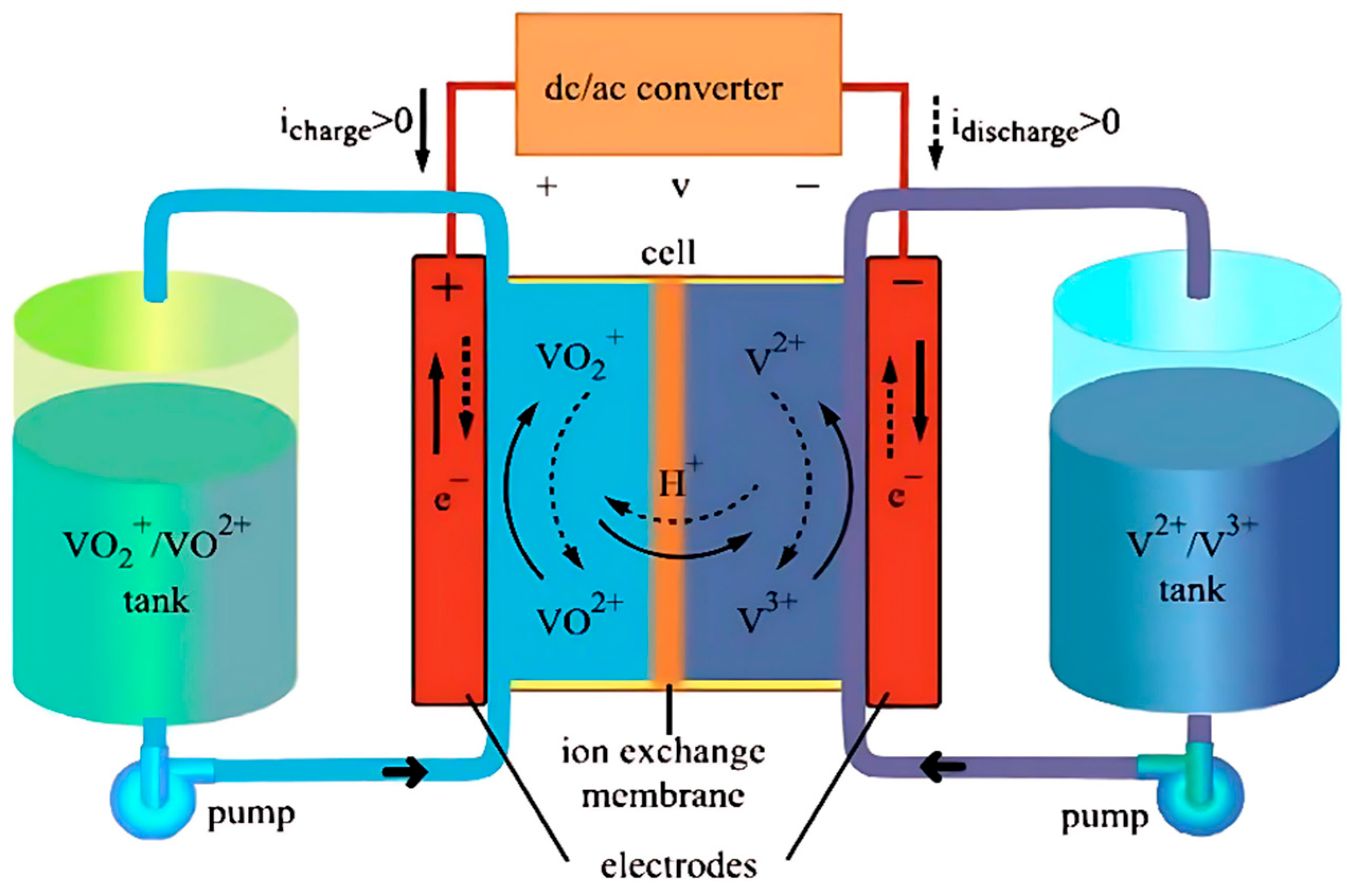
Figure 1. Schematic diagram of the geometric structure of a flow battery, illustrating the main components including electrolyte tanks and the battery stack. Reprinted with permission from Ref. [9] 2019, Wiley.
Energies 18 04170 g001
Figure 2. Schematic of a redox flow battery structure and internal porous electrode reactions, illustrating the redox reactions occurring at the electrode–electrolyte interface. Reprinted with permission from Ref. [36], 2019, Elsevier.
Energies 18 04170 g002
Figure 3. Effect of electrode compression ratio on battery performance. (a) Charge–discharge curves of the battery under different compression ratios. Reprinted with permission from Ref. [40], 2019, Hindawi; (b) Discharge voltage of the VRFB with electrodes subjected to various compression ratios. Reprinted with permission from Ref. [41], 2025, Elsevier.
Energies 18 04170 g003
Figure 4. Influence of electrode thickness on battery performance. (a) Polarization curves of VRFBs with varying electrode thicknesses. Reprinted with permission from Ref. [44], 2023, Elsevier; (b) Charge–discharge curves of the battery under different electrode thicknesses. Reprinted with permission from Ref. [45], 2019, Elsevier.
Energies 18 04170 g004
Figure 5. Coupled effects of electrode thickness and porosity on cell voltage at different current densities. Reprinted with permission from Ref. [41], 2025, Elsevier.
Energies 18 04170 g005
Figure 6. Different flow field structures and reactant concentration distributions. Reprinted with permission from Ref. [51], 2022, Elsevier. (a) Schematic diagram and concentration contour of the serpentine flow field structure. (b) Schematic diagram and concentration contour of the interdigitated flow field structure.
Energies 18 04170 g006
Figure 7. Schematic diagrams of ionic convection, diffusion, and migration. (a) Diffusion; (b) migration; (c) convection. Reprinted with permission from Ref. [53], 2024, Springer Nature.
Energies 18 04170 g007
Figure 8. Concentration distribution of different ions in the negative electrode, membrane, and positive electrode of the battery. (a) H+ and HSO4− concentrations in cation-exchange membrane, (b) H+ and HSO4− concentrations in anion-exchange membrane, (c) vanadium ions concentrations in cation-exchange membrane, (d) vanadium ions concentrations in anion-exchange membrane. Reprinted with permission from Ref. [64], 2019, IOP Science.
Energies 18 04170 g008
Figure 9. Simulation results of the ion-selective adsorption model and description of the continuous Donnan-effect model. (a) Crossover of VO2+ in the VRFB with and without ion selective adsorption considered, including diffusion (Diff), convection (Conv) and migration (Mig) terms. Reprinted with permission from Ref. [65], 2018, Elsevier. (b) Charge schematic at the M-E interfacial region. Reprinted with permission from Ref. [23], 2015, Elsevier.
Energies 18 04170 g009
Figure 10. Illustration of water source/sink terms representing various reactions and transport mechanisms during charging and discharging. Reprinted with permission from Ref. [69], 2019, Elsevier.
Energies 18 04170 g010
Figure 11. A schematic of single cell VRFB with different spatial dimensions: (a) 3D model, (b) 2D model, (c) 1D model, and (d) 0D model. Reprinted with permission from Ref. [78], 2022, IOP Science.
Energies 18 04170 g011
Figure 12. General scheme of a state observer for a VRFB. Reprinted with permission from Ref. [79], 2022, MDPI.
Energies 18 04170 g012
Figure 13. Microscale modeling analysis. (a) Porous structures of the reconstructed fibrous electrodes with different porosity and fiber diameter. Reprinted with permission from Ref. [71], 2017, Elsevier. (b) Visualizing the electrode network of pores and channels by their diameter. Reprinted with permission from Ref. [87], 2023, IOP Science. (c) Displacement distributions of carbon felt model in Z direction at compression ratios of 10%, 20%, and 30%. Reprinted with permission from Ref. [88], 2020, IOP Science.
Energies 18 04170 g013
Figure 14. Framework of multi-scale model for local polarization prediction and flow rate optimization. Reprinted with permission from Ref. [94], 2023, Elsevier.
Energies 18 04170 g014
Figure 15. The neural network architecture and the forward propagation process for building the loss function. Reprinted with permission from Ref. [95], 2023, Elsevier.
Energies 18 04170 g015
Figure 16. Scheme of a zinc-iron flow battery. Reprinted with permission from Ref. [123], 2021, Elsevier.
Energies 18 04170 g016
Figure 17. Morphologies of the negative electrode before and after cycling test. (A) shows the optical image of the negative electrode after charging, (B and C) present the SEM and magnified SEM images of its surface morphology, respectively; (A’, B’ and C’) correspond to the optical, SEM, and magnified SEM images of the negative electrode after discharging. Reprinted with permission from Ref. [125], 2018, Cell Press.
Energies 18 04170 g017
Figure 18. Battery performance and concentration distribution of Zn(OH)42− at the negative electrode under different flow rates, electrode thicknesses, and porosities. (a) Different flow rates; (b) different electrode thicknesses; (c) different porosities. Reprinted with permission from Ref. [123], 2021, Elsevier.
Energies 18 04170 g018
Figure 19. Zinc dendrite morphology under different conditions. Reprinted with permission from Ref. [127], 2024, Elsevier. (a) At different voltages; (b) At different anisotropy strengths; (c) At different flow velocities.
Energies 18 04170 g019
Figure 20. Schematic diagram of HBRFB operation. Reprinted with permission from Ref. [142], 2022, Elsevier.
Energies 18 04170 g020
Figure 21. Comparison between the single-phase and two-phase models in the HBRFB. (a) Comparison of the simulated cell voltage profiles obtained from the single-phase and two-phase models; (b) HBr concentration distribution inside the cell during discharge predicted by the single-phase model; (c) HBr concentration distribution during discharge predicted by the two-phase model. Reprinted with permission from Ref. [142], 2022, Elsevier.
Energies 18 04170 g021
Table 1. Key characteristics and modeling features of major aqueous flow batteries.
Battery SystemReaction CharacteristicsModeling Features
VRFBLiquid–liquidMass conservation equation; Nernst–Planck equation; Charge conservation equation; Butler–Volmer equation
ZFBLiquid–liquidSimilar modeling equations as in VRFB, with additional consideration of porous electrode gap variation; For studying zinc dendrite issues involving solid–liquid phase transitions, embed Butler–Volmer kinetics into the Allen–Cahn equation to form a non-equilibrium reaction phase-field model
HBFBLiquid–gasSimilar modeling approach to VRFB, but the presence of two-phase flow at the hydrogen electrode requires all related physical quantities to be evaluated using multiphase flow theory
Table 2. Microscale and multi-scale modeling approaches.
Model TypeDescriptionModeling ScaleModeling Methods
Lumped parameter modelsTreat the battery as one or more integrated reaction units, assuming that key variables (e.g., concentration, potential, temperature) are spatially uniform and vary only with time.MacroscaleFinite element method;
Finite volume method
Microscale modelingFocuses on fundamental physical and electrochemical processes at the electrode–electrolyte interface and within the pore structure of porous electrodes.Pore scaleFinite element method;
Finite volume method;
LBM;
PNM;
Multi-scale modelingIntegrates microscale features such as electrode pore structure and transport properties into macroscale models to enhance accuracy and applicability.Pore scale + MacroscalePNM;
LBM;
PINN;
Deep neural networks
Disclaimer/Publisher’s Note: The statements, opinions and data contained in all publications are solely those of the individual author(s) and contributor(s) and not of MDPI and/or the editor(s). MDPI and/or the editor(s) disclaim responsibility for any injury to people or property resulting from any ideas, methods, instructions or products referred to in the content.