1. Introduction
The global energy transition has accelerated the search for sustainable solutions capable of addressing the increasing global demand for electricity while mitigating environmental impacts. Among key objectives are decarbonization of the energy sector, reduction in greenhouse gas (GHG) emissions, and increase in the share of renewable energy sources in the global energy matrix [
1,
2,
3].
In this context, hydrogen has emerged as a promising and versatile energy vector, primarily due to its ability to store large amounts of energy over extended periods and its potential for sectoral coupling, integrating the power, transport, and industrial sectors [
4,
5]. When powered by renewable energy, its production through water electrolysis is essential to achieving the deep decarbonization targets aligned with the Paris Agreement [
6,
7].
However, efficient hydrogen production through electrolysis requires optimized energy management, especially when embedded within microgrids supplied by variable renewable energy sources, such as solar and wind power. These resources introduce intermittency and uncertainty into power systems, challenging the stability and efficiency of hydrogen production [
8].
Microgrids are localized and controllable energy systems that combine distributed generation, energy storage systems, controllable loads, and often combined heat and power (CHP) units, operating in both grid-connected and islanded modes [
9,
10,
11]. They offer multiple benefits, including increased resilience, energy autonomy, and operational flexibility. Recent developments in smart microgrids emphasize the role of advanced control systems and real-time optimization to dynamically balance energy supply and demand, addressing the complexity introduced by high shares of renewable energy [
12,
13,
14,
15,
16].
Regarding the integration of hydrogen systems into microgrids, a growing body of research has explored the synergistic role of electrolyzers as controllable loads that provide both energy storage and grid-balancing services [
17,
18]. García-Triviño et al. [
19] developed a supervisory control system for a grid-connected medium-voltage direct current microgrid that integrates photovoltaic (PV) generation, battery storage, a hydrogen production system, and electric vehicle charging infrastructure. Similarly, Shen et al. [
20] proposed a real-time energy scheduling strategy using meta-reinforcement learning, improving both energy utilization efficiency and operational cost-effectiveness in the early stages of microgrid deployment.
The core research objective of this study is to implement and experimentally validate a modular microgrid system for hydrogen production, capable of integrating multiple energy sources—photovoltaic, cogeneration, battery storage, and grid connection—within a real-world application environment. Rather than testing a specific hypothesis or comparing alternative methodologies, the primary goal is to confirm the system’s technical feasibility, stability, and interoperability under realistic operating conditions. This provides a robust foundation for future research focused on intelligent control strategies, system scalability, and techno-economic optimization.
The novelty of the proposed system lies in its unique combination of modularity, hybrid energy integration, and application-oriented design, distinguishing it from conventional hydrogen production setups. The system adopts a modular and compartmentalized architecture, where each physical skid is dedicated to a specific function—generation, conversion, storage, or control—enabling greater flexibility, reconfigurability, and scalability. Furthermore, the integration of photovoltaic generation, battery storage, cogeneration, and grid connection allow for multiple coordinated operating modes, including islanded operation, with seamless energy balancing.
The system is specifically designed for deployment in a thermoelectric power plant environment, incorporating a liquefied petroleum gas generator to emulate combined heat and power conditions and assess the potential for waste heat recovery—an aspect rarely considered in compact hydrogen production setups. It also features a battery inverter configured to manage both energy flow and power quality, offering services such as harmonic compensation and reactive power injection to mitigate disturbances from high-power electrolyzers. Although the current implementation uses basic supervisory logic, the system serves as a testbed for advanced energy management strategies, including a patented control approach (BR102023015567-7) [
21] based on random forests optimized by genetic algorithms. This strategy aims to enable real-time decision-making based on dynamic parameters, including energy prices, load forecasting, and total harmonic distortion. Additionally, a blockchain infrastructure is integrated to ensure the traceability and certification of green hydrogen, addressing the growing demand for transparency and supporting future participation in carbon credit schemes.
The remainder of this paper is structured as follows:
Section 2 presents the structure and equipment of the modular skid.
Section 3 discusses the experimental results related to skid operation. Finally,
Section 4 summarizes the key findings and provides directions for future research.
2. Modular and Smart Microgrid Architecture for Hydrogen Production
The skid developed is based on a modular microgrid designed to optimize the use of multiple energy sources for hydrogen production. Its modular architecture allows for easy replication and adaptation to various industrial contexts, promoting scalability and flexibility.
All equipment and procedures follow international technical standards, such as ATEX regulations applicable to potentially explosive atmospheres, and NFPA (National Fire Protection Association) standards, aimed at fire safety.
A supervisory module provides critical operational indicators related to energy performance, consumption, and efficiency in real time. This module ensures communication through industrial protocols such as Modbus-RTU and Modbus-TCP/IP, enabling integration with power plant supervisory systems and enhancing operational predictability.
Figure 1 presents the schematic of the skid installation, highlighting the compartmental organization and integration of the key subsystems involved in the project.
The skid is divided into six compartments:
Control and power supply system: The first compartment centralizes the control, monitoring, and safety systems, ensuring the real-time management of the microgrid and the operational integrity of the electrolyzer.
Battery storage: The second compartment houses the battery system, ensuring energy storage and operational continuity for the microgrid.
Photovoltaic and Battery storage interface: The third compartment manages solar energy conversion and battery interfacing, ensuring the efficient integration of photovoltaic generation into the microgrid through advanced inverters, converters, and power quality controls.
LPG generator: The fourth compartment houses the LPG generator (emulating a cogeneration system) and its inverter, providing backup power, grid stabilization, and optimized energy support for hydrogen production.
PEM electrolyzer: The fifth compartment houses the PEM electrolyzer, enabling high-purity hydrogen production.
Booster, sensors, valves, and pressure regulators: The final compartment ensures system safety and integrity through advanced monitoring, ventilation controls, and temporary hydrogen storage before the booster sends it to high-pressure cylinder storage.
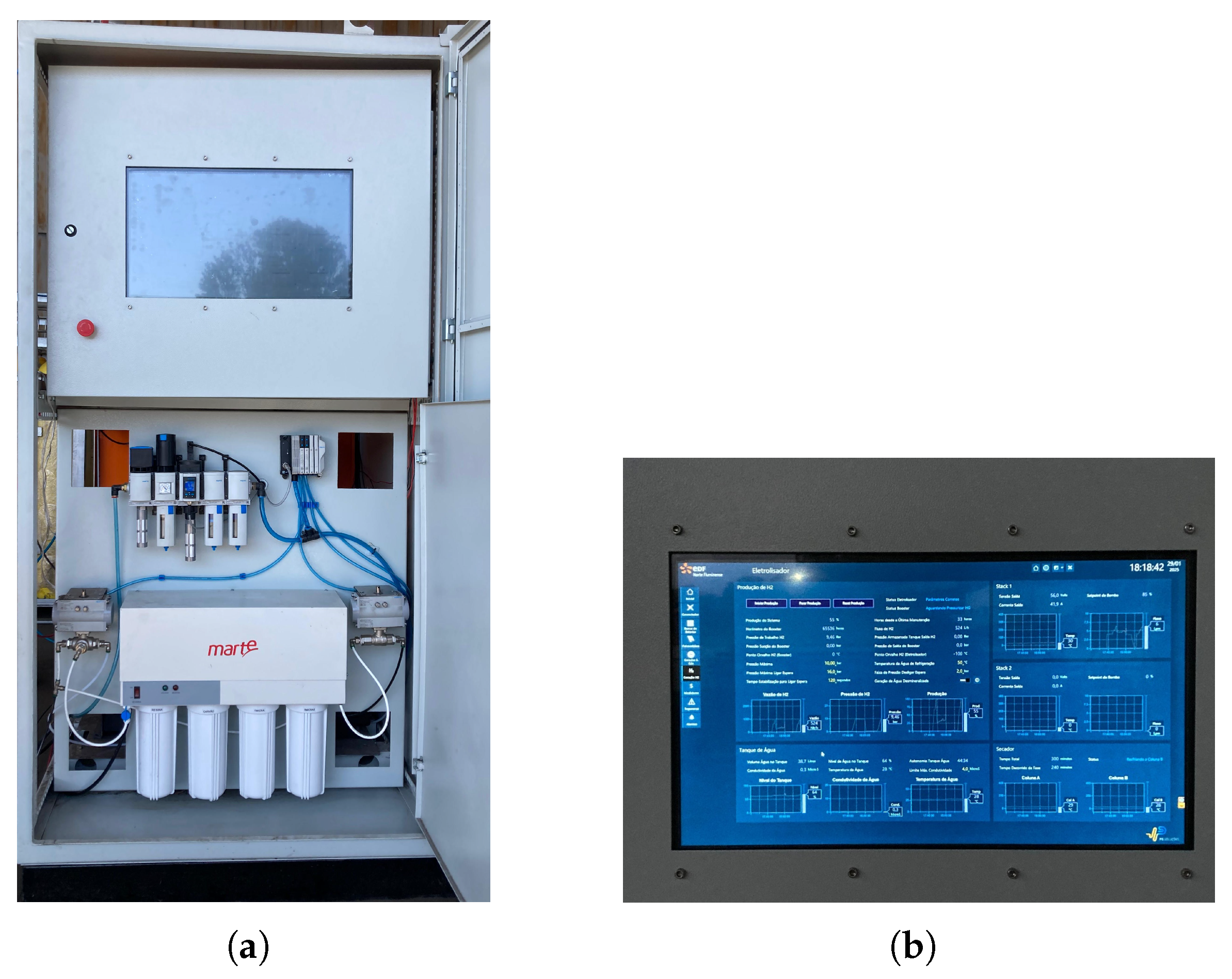
2.1. Control and Power Supply System
The first compartment of the skid plays a strategic role in the centralized management of the microgrid. It houses the control and monitoring system, which includes a computer and a touchscreen display designed to facilitate real-time tracking of key parameters such as battery state of charge, solar energy generation, and electrolyzer status. This setup also allows for precise adjustments and control over the operation and shutdown of all system components.
The selection of this subsystem followed a power-level-based design approach, where all internal components—such as control electronics, instrumentation, and auxiliary systems—were dimensioned according to the nominal energy flows within the modular skid. In addition, integration compatibility with the SCADA system guided the choice of devices supporting Modbus TCP/IP communication.
Additionally, the compartment is equipped with fire protection equipment, a CO2 suppression system, and an uninterruptible power supply (UPS) to ensure operational continuity during power failures. It also contains meters for photovoltaic generation and electrolyzer consumption, which are essential for the blockchain-based certification of green hydrogen production.
At the bottom of this compartment is the demineralized water treatment system, which employs multi-stage filters (including activated carbon, reverse osmosis membranes, and ion exchange resins) to deliver water with conductivity below 1 S/cm, which is essential for the operation of the electrolyzer. Pressurized air supplied by the plant is regulated to approximately 6 bar through an integrated conditioning system that also removes particles and moisture, ensuring the protection of internal components.
Figure 2 shows images of the control and power supply system compartment. In
Figure 2a, the internal components are displayed, and in
Figure 2b, the human–machine interface (HMI), responsible for the real-time monitoring of operational variables and control of the skid’s functions, is shown.
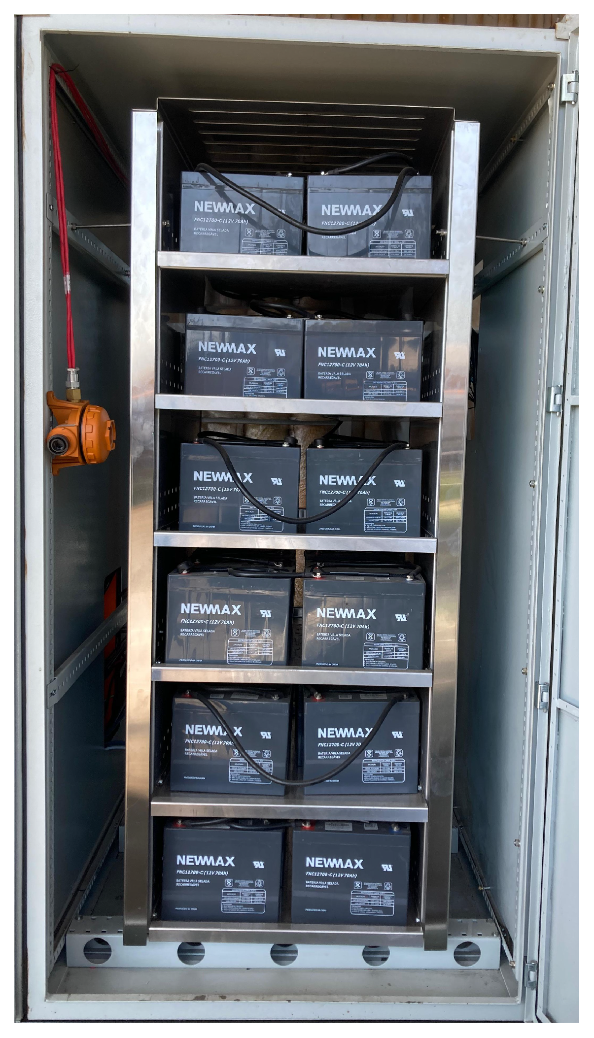
2.2. Battery Storage
The second compartment of the skid is dedicated to energy storage and houses 36 sealed lead–acid batteries with a nominal capacity of 70 Ah. This battery bank was selected based on lead–acid technology due to its lower cost compared to lithium-ion alternatives, as well as its operational robustness and ease of maintenance—characteristics particularly suitable for field-deployable modular systems. Designed to provide energy support for the microgrid, battery banks ensure continuity of operations even during periods of low renewable generation, thus contributing to overall system stability. As in the first compartment, this section is also equipped with a CO2-based fire suppression system. Battery discharge was managed to avoid deep cycling, with the state of charge (SoC) maintained above a minimum threshold of 20%, preserving battery health and extending system life.
Figure 3 shows the energy storage compartment installed in the skid, highlighting the battery layout and internal organization of the system.
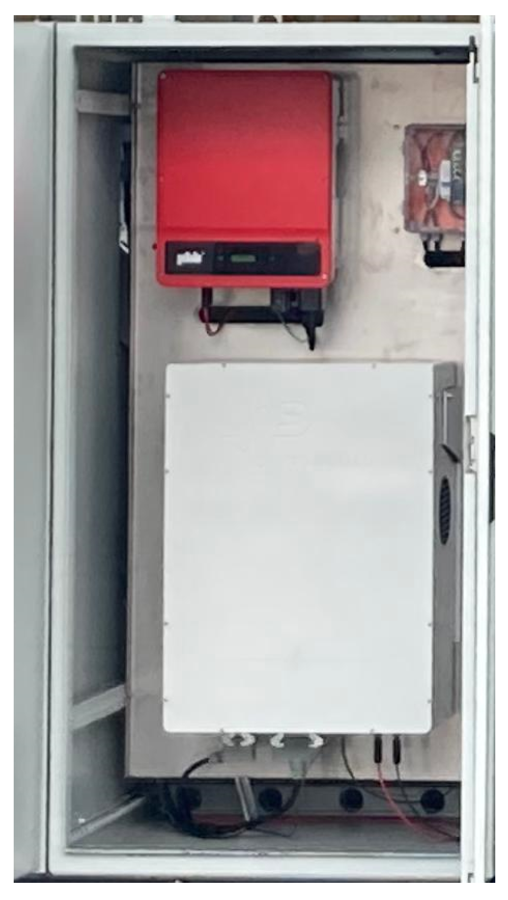
2.3. Photovoltaic and Battery Storage Interface
The third compartment of the skid is dedicated to managing the energy generated by the photovoltaic panels and to communicating with the battery storage system. It houses the PHB12KF-DT photovoltaic inverter, manufactured by PHB Solar (Sao Paulo, Brazil), which converts the direct current produced by 22 solar modules into alternating current compatible with the microgrid. With a nominal output power of 12 kW and a maximum efficiency of 98.4%, the inverter features maximum power point tracking (MPPT) technology to ensure optimal solar energy harvesting, even under fluctuating irradiation or partial shading conditions.
The photovoltaic modules were selected from commercially available options that provided a good cost–benefit ratio and supported Modbus communication, ensuring compatibility with the supervisory system. The inverter was dimensioned based on the total installed PV capacity and designed to match the power requirements of the electrolyzer and other critical loads.
To support functionalities such as islanded operation, battery control, harmonic compensation, and reactive power support, the battery inverter was custom-developed by the project team. This approach allowed for the implementation of tailor-made control logic and ensured seamless integration with the SCADA platform.
The compartment also includes a three-phase converter developed during this project for regulating battery charging and discharging. Although physically located in the third compartment, it operates in conjunction with the second compartment, which houses the battery storage. This converter incorporates an LCL filter that mitigates high-frequency noise generated during switching operations, thereby ensuring efficient performance and minimizing electromagnetic interference. Its control system is based on a TMS28379D microcontroller, which continuously monitors the battery’s state of charge, adjusts the current, and implements protective actions to preserve component integrity. As with the other compartments, this one is also equipped with a CO2-based fire suppression system.
Figure 4 shows the compartment responsible for photovoltaic management, highlighting the arrangement of the inverters and converters used to integrate solar energy into the system. The image highlights the placement of the PHB12KF-DT photovoltaic inverter (top), responsible for converting solar energy into alternating current, and the three-phase converter (bottom), which manages battery charging, discharging, island mode, reactive power, and harmonic compensation.
Reactive power compensation reduces system losses by supplying part of the reactive power demanded by the load via the battery converter. Additionally, it improves the microgrid’s voltage profile. Harmonic current compensation, in turn, prevents the overheating and degradation of critical microgrid components such as transformers and capacitors. These functionalities become even more relevant in higher-power systems and configurations employing thyristor-based electrolyzers, which are inherently more susceptible to issues related to reactive power and harmonic distortion. In such scenarios, effective compensation can significantly enhance system stability, efficiency, and component longevity.
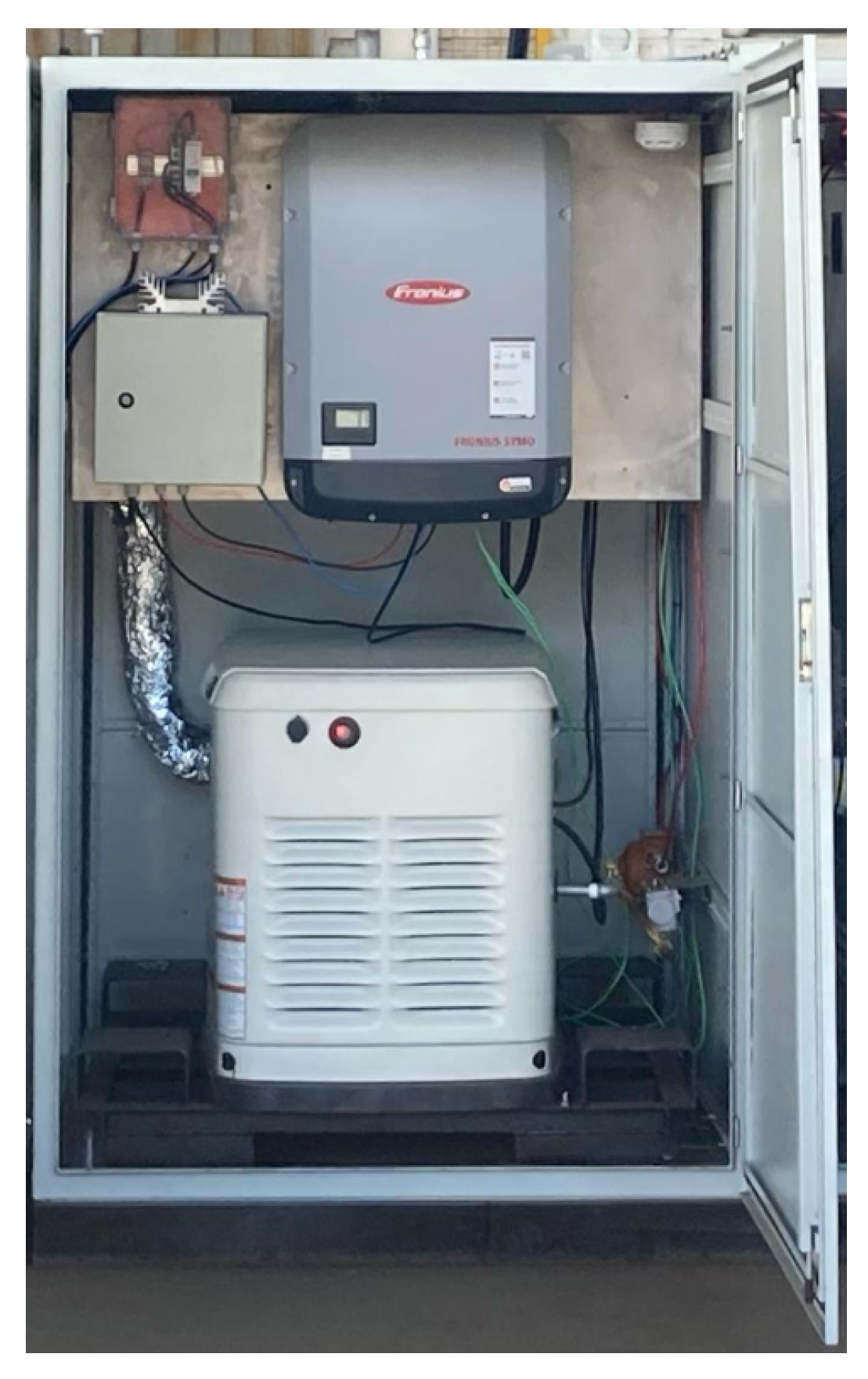
2.4. LPG Generator
The fourth compartment of the skid houses an LPG generator, employed to emulate a cogeneration system. In thermoelectric power plants, significant energy losses commonly occur, primarily in the form of heat. Cogeneration offers an effective strategy to recover this otherwise wasted thermal energy for additional power generation.
At the EDF plant, it was identified that a cogeneration system could recover approximately 1.5 MW of mechanical energy per gas turbine, which can be converted into electrical energy. Since the plant operates three gas turbines, the total potential for energy recovery is about 4.5 MW, which could be harnessed for power generation and indirectly mitigate the plant’s environmental footprint. Anticipating the need to address this opportunity in the full-scale model, a dedicated compartment was designed for this function. Consequently, an LPG generator was selected to simulate cogeneration and demonstrate how recovered energy can be effectively utilized, also serving development and research purposes. However, in the current scale, the cogeneration method has not yet been integrated due to the significant power disparity between the skid and the EDF plant.
The generator was dimensioned to meet the power demand of the skid’s components, ensuring that it could reliably support system operation when needed. The decision to use gas as a fuel was motivated by its high availability at the plant site, which simplifies logistics and facilitates experimental operation during test campaigns.
The generator, a Generac Guardian model with a nominal capacity of 20 kW, was adapted to operate in synchronization with the plant’s electrical grid, overcoming its initial limitation of standalone operation. This adaptation was made possible through the integration of an inverter specifically configured to synchronize the generator with the grid. The energy produced can be either injected into the grid or stored in the battery bank, with intelligent control directing its use to the PEM electrolyzer for hydrogen production as needed.
The inverter plays a key role in generator management, enabling precise control over dispatched power and ensuring operational flexibility. It also facilitates dynamic balancing of the microgrid by automatically adjusting the generator’s output according to load variations and the availability of renewable energy sources.
The compartment is also equipped with advanced safety sensors for LPG leak detection. These sensors are integrated into the supervisory system and provide real-time alerts, allowing for prompt and effective responses to any anomalies. The fire protection system is complemented by smoke detectors and a CO2 suppression system.
Figure 5 illustrates the compartment responsible for the operation of the LPG generator, highlighting the integration of the equipment with the inverter and control systems. The image shows the Generac Guardian generator connected to the inverter responsible for grid synchronization. This setup enables microgrid stabilization and optimized energy utilization for hydrogen production. Additionally, the presence of safety sensors ensures continuous monitoring, supporting safe and efficient operation.
2.5. PEM Electrolyzer
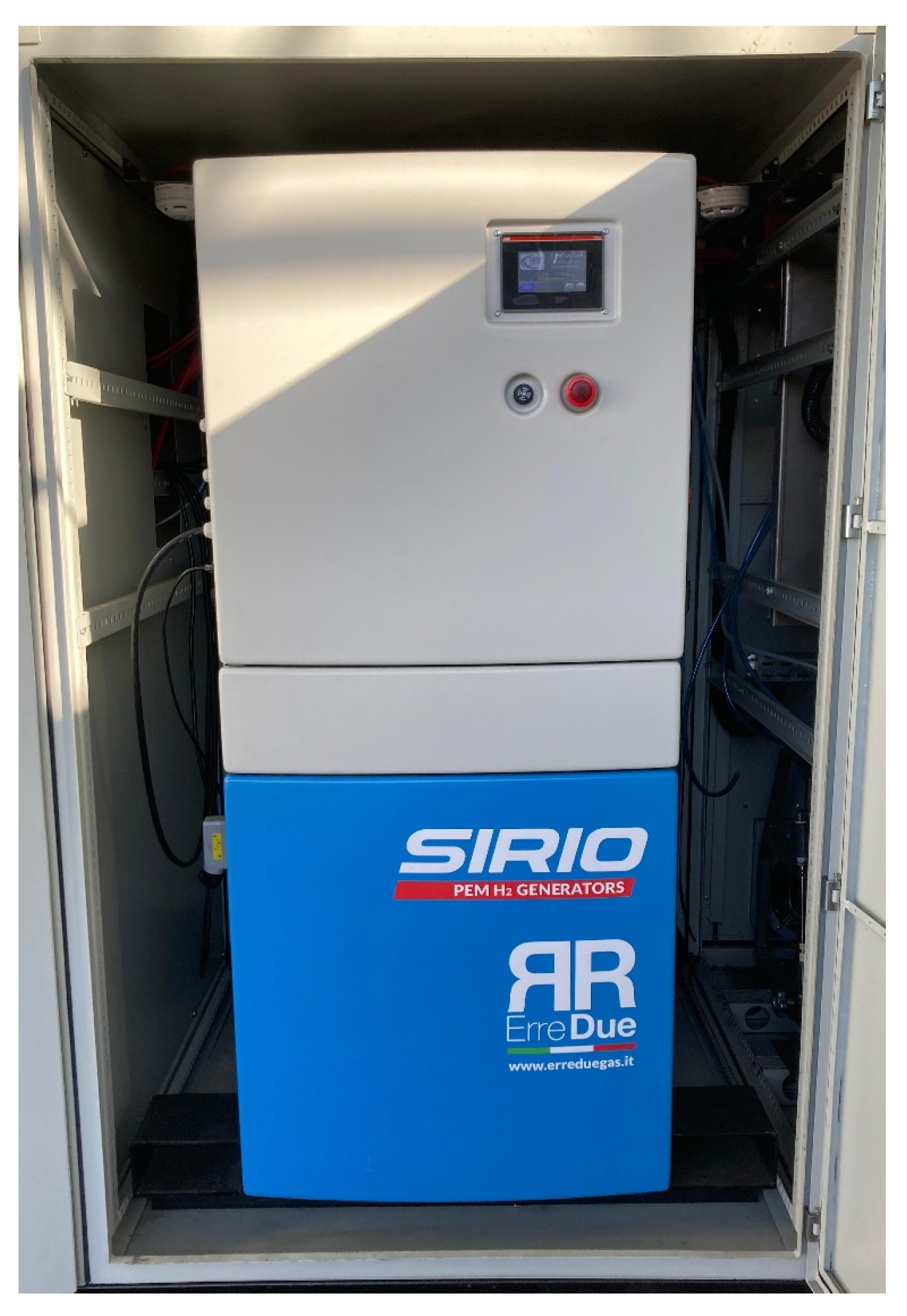
The fifth compartment of the skid is dedicated to the PEM electrolyzer, model Sirio 75, manufactured by Erre Due (Livorno, Italy)—a device designed for the production of high-purity hydrogen. This electrolyzer operates using electrical energy sourced from renewable generation and recovered waste heat from the thermoelectric plant (LPG generator), ensuring a sustainable solution for hydrogen production.
The selection of this electrolyzer was based on two primary criteria: its relatively low power demand and its ability to produce hydrogen with a purity level of 99.999%, which is required for the thermal insulation of generator windings in the thermoelectric plant. A PEM-type electrolyzer was favored over alkaline alternatives, which would require additional purification stages to reach the same purity, increasing system complexity and cost.
The Sirio 75 meets the highest quality standards. The electrolyzer can produce H2 at a nominal capacity of 0.75 Nm3/h. a specific energy consumption of 4.6 kWh per Nm3 of hydrogen, resulting in roughly 51.2 kWh per kilogram considering the density of hydrogen at standard conditions (1 kg ≈ 11.2 Nm3); a hydrogen purity equal to or greater than 99.999%, achieved without the need for additional gas purification stages; an operating pressure set at 15 bar; and an estimated electrical efficiency of approximately 65%, based on the hydrogen lower heating value (LHV ≈ 33.3 kWh/kg).
The system is equipped with an advanced control panel that enables the real-time monitoring of operational variables such as flow rate, pressure, and hydrogen quality. For integration with the microgrid, the electrolyzer is configured with Ethernet connectivity and the Modbus TCP/IP protocol.
To mitigate risks associated with hydrogen, the compartment is equipped with an H2 gas analyzer that continuously detects hydrogen levels and emits visual and audible alerts when critical concentrations are reached. Furthermore, the fire suppression system uses CO2 in a total flooding configuration, triggered by a logic system based on two detection zones with two smoke detectors.
Figure 6 shows the compartment housing the Sirio 75 PEM electrolyzer, manufactured by Erre Due, which is responsible for producing high-purity hydrogen.
2.6. Booster, Sensors, Valves, and Pressure Regulators
This final compartment of the skid plays a crucial role in maintaining the integrity and safety of the entire system. It is equipped with sensors designed to continuously monitor critical variables such as hydrogen leaks, internal temperature, and the presence of smoke. These sensors are integrated into a safety system that, upon detecting any irregularities, triggers audiovisual alarms and, if necessary, an automatic CO2 suppression system. This system is activated only upon cross-verification between two sensors located within the same compartment.
In addition, the compartment includes valves and control systems that manage ventilation and isolate other compartments, preventing the spread of gases or flames. It is also equipped with remote control interfaces, which enable the continuous supervision of all systems through the first compartment, where operational data are centralized.
Finally, this compartment also houses a 20-liter tank used as a hydrogen buffer before delivery to the booster, which raises the pressure from 15 bar to 200 bar before transferring the gas to the high-pressure storage cylinders.
To meet the pressure requirements of the plant’s hydrogen distribution infrastructure (200 bar), a pneumatically driven booster was selected. This decision leveraged the availability of an existing compressed air line at the facility, reducing electrical integration complexity and operational costs while ensuring compatibility with the existing hydrogen handling protocols.
Figure 7 illustrates the internal configuration of the final compartment.
Figure 7a shows an overview of the compartment, including the 20-liter tank for temporary hydrogen storage before it is sent to the booster and, subsequently, to the high-pressure cylinders.
Figure 7b highlights the booster—responsible for increasing hydrogen pressure before permanent storage—alongside sensors, valves, and pressure regulators that ensure safe system operation.
Figure 7c shows the cylinder basket used for hydrogen storage.
2.7. Blockchain for Green Hydrogen Certification
With the regulatory framework for hydrogen still in its early stages, several aspects related to the classification of hydrogen by color and its potential commercialization pathways remain under debate. In the case of green hydrogen—specifically produced via electrolysis powered by renewable energy sources—energy traceability emerges as a fundamental concern.
According to the guidelines issued by the Electric Energy Trading Chamber (CCEE), energy traceability can be classified in two ways. First, the hydrogen producer is connected to the national interconnected system and purchases energy from renewable generators through a power purchase agreement (PPA). Second, the hydrogen producer operates its renewable generation sources on-site. In both scenarios, the amount of green hydrogen produced is proportional to the volume of renewable energy either contracted (scenario 1) or self-generated (scenario 2) by the producer.
Moreover, the green hydrogen value chain facilitates the generation of carbon credits by renewable energy producers, which can be traded in voluntary markets due to the current lack of binding regulations on this matter in Brazil. However, this regulatory gap makes carbon credit transactions vulnerable to fraudulent practices by market participants, such as the double-selling of the same credit to multiple buyers. At the EDF plant, the implementation of a full-scale skid would enable the blending of green hydrogen with natural gas. This substitution would lead to fuel savings and, consequently, the generation of additional carbon credits for the plant.
To address the challenges of ensuring reliable traceability of renewable energy used in green hydrogen production—as well as the associated carbon credits—a blockchain-based system has been adopted. These systems function as shared and immutable ledgers that facilitate the recording of transactions and the tracking of assets within a business network [
22]. Blockchain networks are decentralized and leverage transparency to reduce the need for trust among participants. Their immutability prevents the alteration of recorded transactions. Additionally, blockchain systems incorporate consensus mechanisms to regulate how participants validate and record data.
These features offer several advantages, including enhanced trust among stakeholders, improved transaction security, and increased operational efficiency. Specifically, through the use of smart contracts, blockchain eliminates the need for time-consuming reconciliation processes, thereby streamlining transactions within the green hydrogen and carbon credit markets.
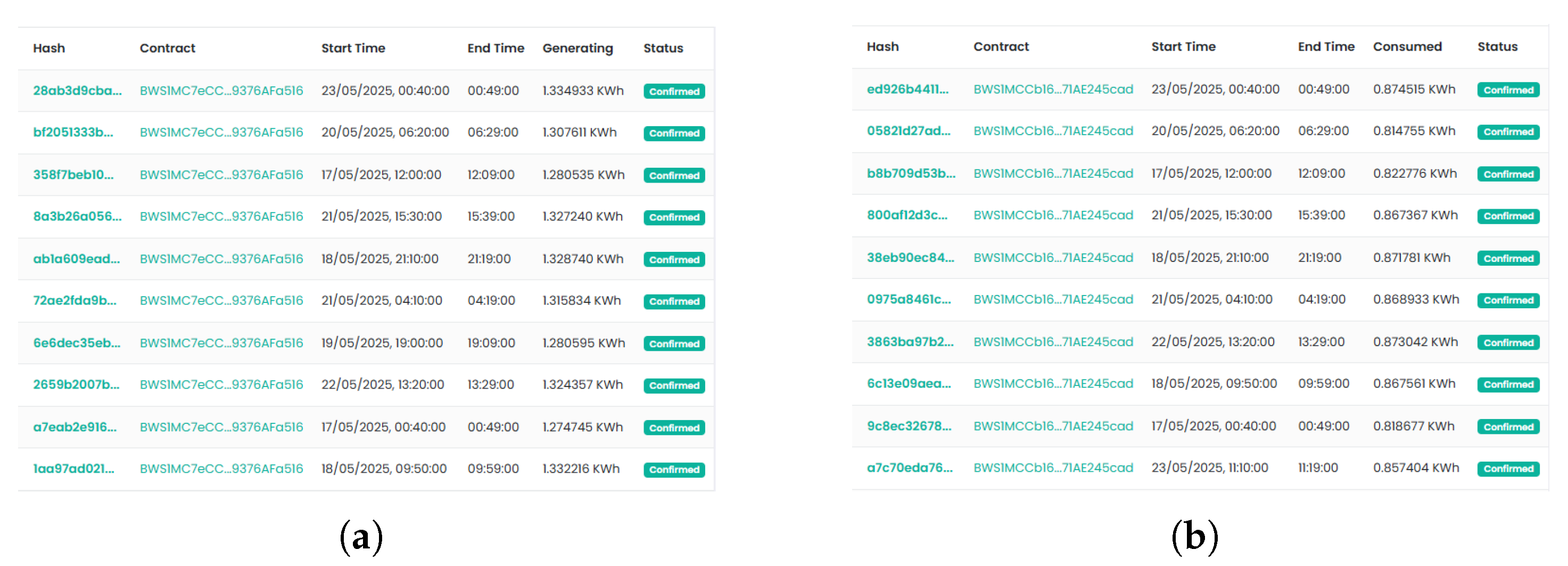
To this end, accurate and reliable meters were installed in the first compartment. These meters perform readings every 10 min and record photovoltaic generation and electrolyzer consumption data on the blockchain. These data enable verification of the proportion of green hydrogen produced by the microgrid.
Figure 8 presents the platform that records the meter data that are available for verification.
3. Results and Discussion
The experimental tests conducted at this stage complement the development phase described by Guimarães et al. [
23], which presented the design and modeling of the main components comprising the microgrid. While the previous study focused on hardware design and the architecture of the control algorithms, the present work advances toward the practical validation of these components, demonstrating the system’s feasibility under real operating conditions.
The experimental setup was deployed outdoors, exposed to the natural environmental conditions of the city of Macaé, Brazil. The tests were conducted over a continuous period of two months, with daily sessions lasting approximately eight hours. During the testing period, ambient temperatures ranged between 21 °C and 34 °C, with an average relative humidity of around 70%, including occasional rainfall. These conditions enabled the assessment of system behavior under realistic and variable operating scenarios, contributing to a robust performance evaluation.
During the tests, each subsystem was initially operated in isolation and subsequently tested in an integrated configuration. Monitoring and control instrumentation were implemented using the Elipse E3 platform, which serves as the supervisory interface for the modular skid system. Data acquisition was carried out using the built-in sensors of the equipment integrated into each compartment of the microgrid, including inverters, battery management systems, the electrolyzer, and gas conditioning units. These sensors measured key operational parameters such as electrical variables, hydrogen production rate, internal temperatures, and system states.
All sensor data were transmitted in real time to the Elipse E3 SCADA system via TCP/IP communication and stored in a structured local database. This architecture enabled high-resolution monitoring, reliable data logging, and full traceability of the system’s dynamic behavior throughout the testing campaign, ensuring consistency and reproducibility of the experimental results.
3.1. Battery Storage Results
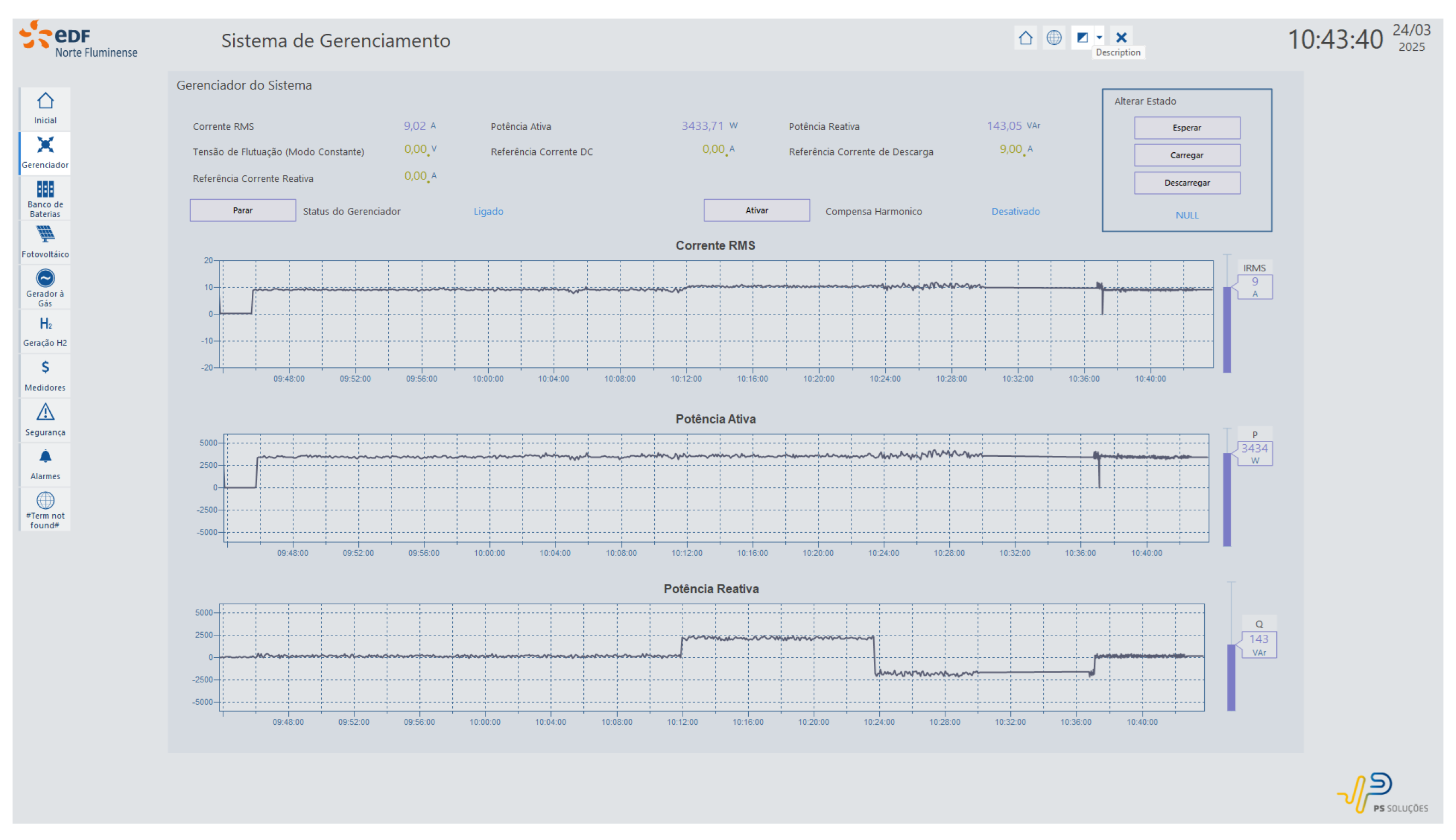
In the first stage, the battery storage system was operated in all available modes. As illustrated in
Figure 9, which shows the supervisory interface with real-time recorded operating parameters, during discharge mode, an injection of up to 3.5 kW of active power was observed, followed by variations in reactive power with both capacitive and inductive profiles. The converter was initially configured to perform a discharge with 9 A of active current, maintaining the reactive reference at zero. It then proceeded to inject 5 A of inductive current (1.905 Var) and subsequently switched to a capacitive profile with the same magnitude. The system operated stably throughout, with accurate recording of the electrical quantities involved in the process.
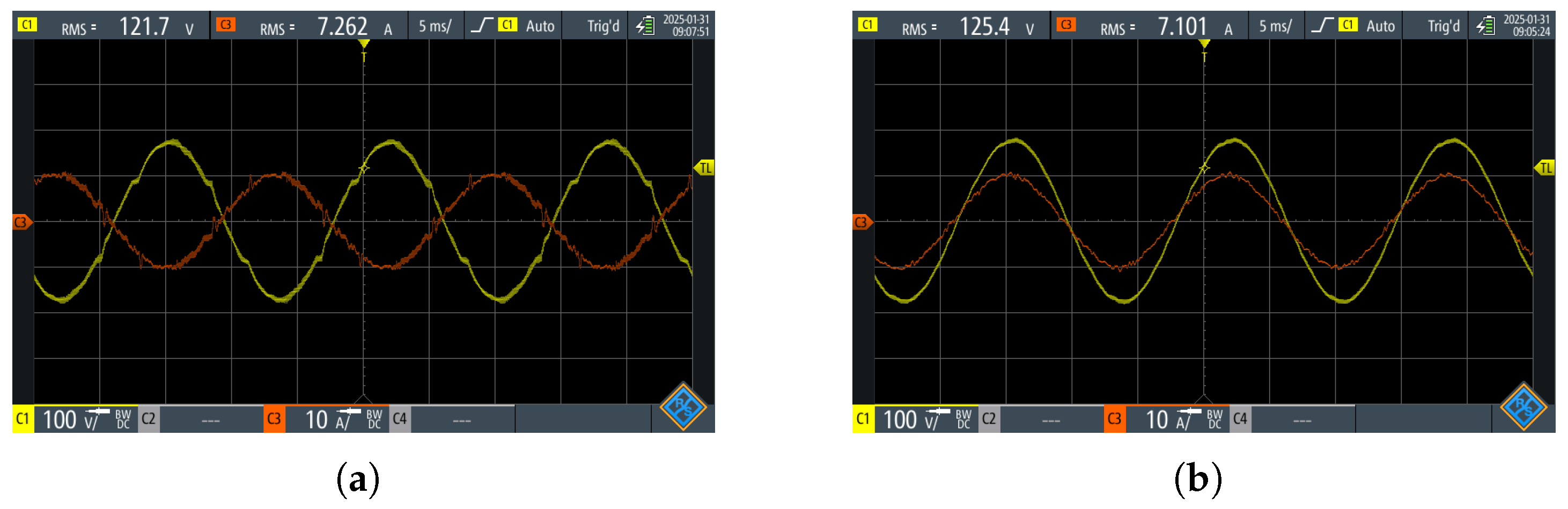
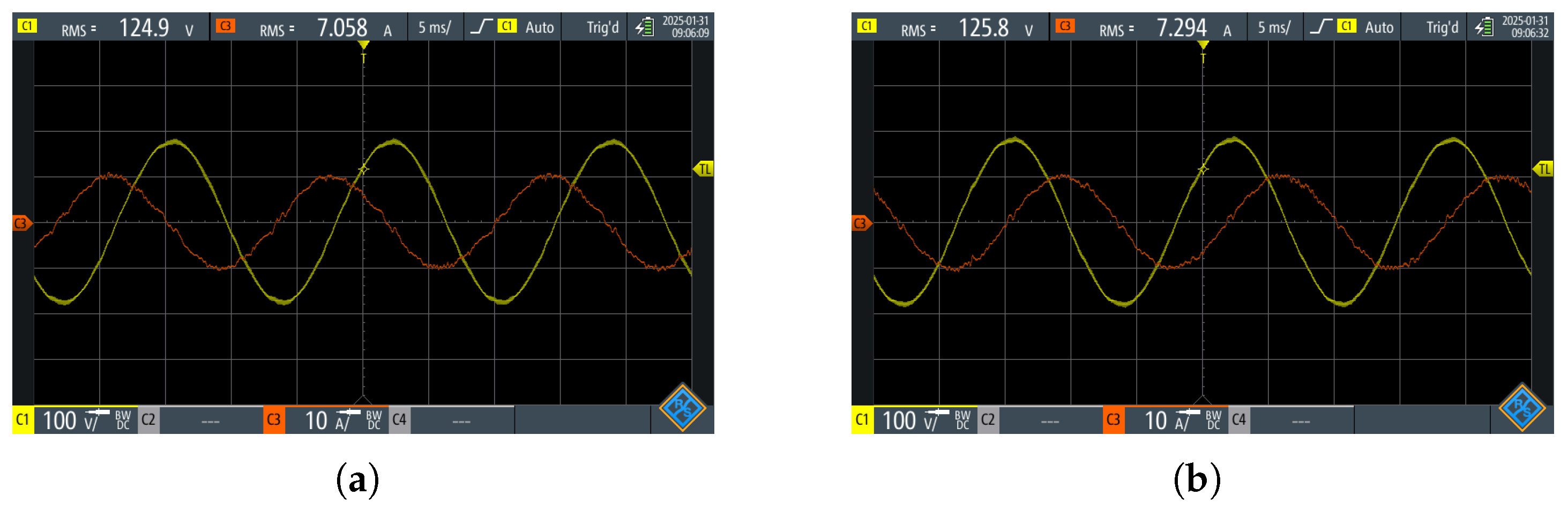
The behavior of the converter during active power handling was verified through the current and voltage waveforms measured at the grid.
Figure 10 presents two distinct situations. In
Figure 10a, the system operates in discharge mode, with the injected current in phase with the grid voltage, characterizing positive active power. In
Figure 10b, the converter operates in charge mode, drawing current from the grid in anti-phase with the voltage, resulting in negative active power. These tests confirmed the converter’s stable and predictable performance during bidirectional power control, validating its role as a dispatchable element within the microgrid.
In addition to active power operation, the converter was tested in reactive power injection modes, with equally satisfactory results. As illustrated in
Figure 11, the waveform behavior confirms precise control of the phase shift between current and voltage. In
Figure 11a, capacitive reactive power injection is observed, with the current leading the grid voltage by 90°. In
Figure 11b, the converter injects inductive reactive power, with the current lagging 90° behind the voltage. These tests demonstrate the system’s capability to provide reactive power compensation within the microgrid, adding further functionality to its operation.
3.2. Harmonic Compensation
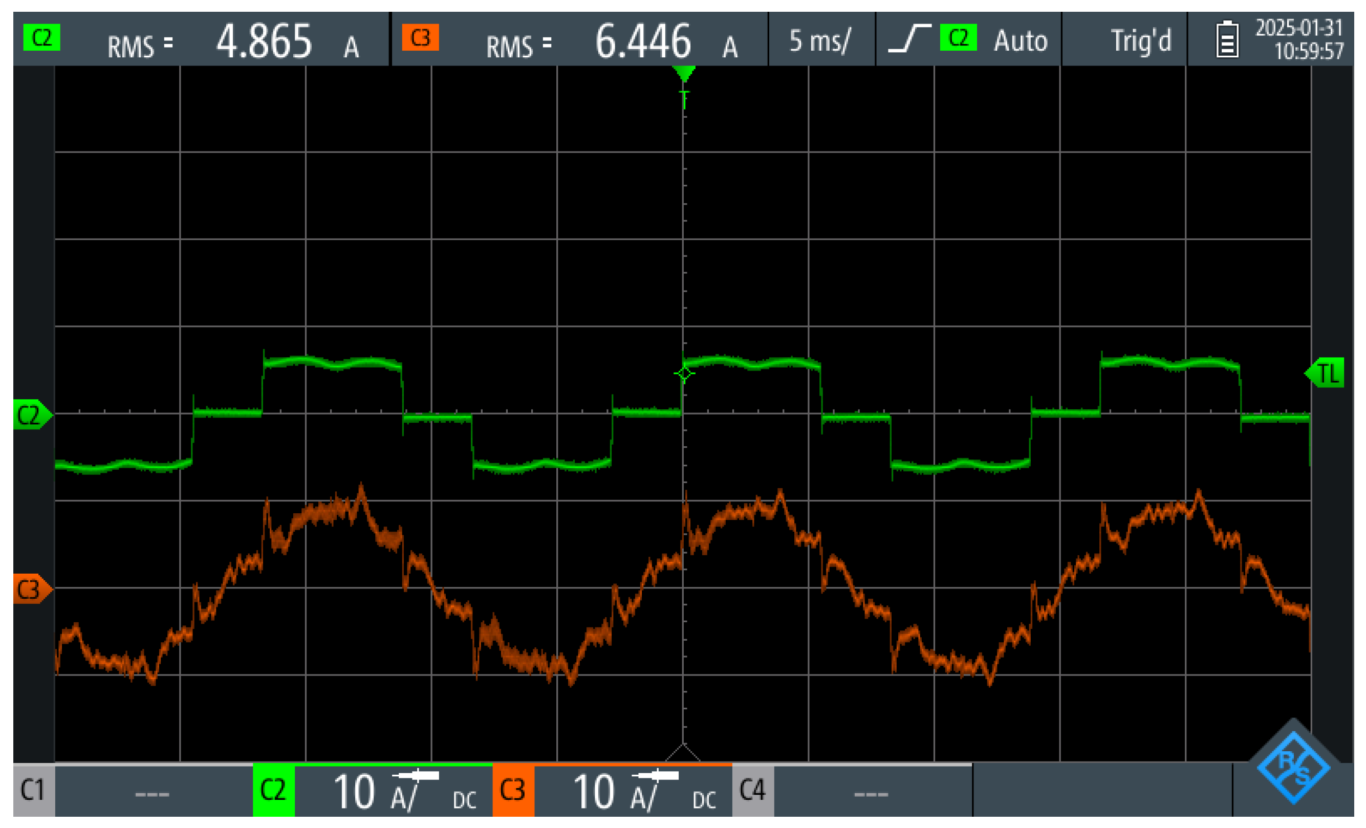
The system’s robustness was also validated through the harmonic compensation mode. For this test, a nonlinear load was connected to the skid bus, introducing significant distortions in the input current.
Figure 12 shows the current signal measured at the skid input after the activation of the compensation mode. It can be observed that, even with the nonlinear load in operation (green signal), the current delivered by the utility to the skid exhibits a waveform significantly closer to an ideal sine wave (red signal). The converter effectively eliminated the harmonic components at 300 Hz and 420 Hz, contributing to power quality and the stability of the microgrid.
3.3. Island Mode Operation
During the tests, the converter was also evaluated in islanded mode to verify its ability to maintain power supply to the load in the event of a main grid outage. A 2 kW resistive load was connected to the microgrid bus and was initially powered by the utility. Upon the occurrence of the simulated outage, the system detected the interruption and autonomously took over the load supply, maintaining the bus voltage within normal operating parameters (127 V).
Figure 13 presents the recorded oscillography, highlighting the transition from grid-connected to islanded mode, with system stability and rapid response.
3.4. Photovoltaic System
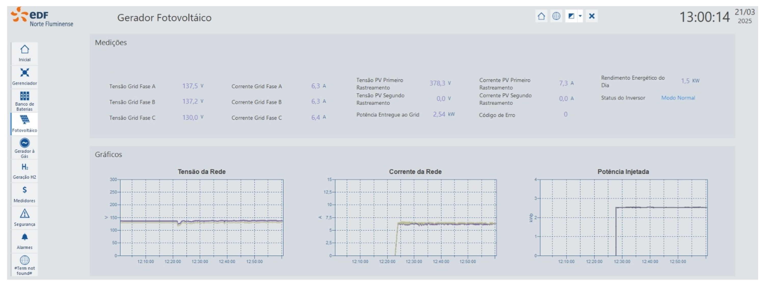
The photovoltaic panels installed at the thermoelectric plant supply power directly to the microgrid.
Figure 14 shows the supervisory interface during system operation, highlighting the proper functioning of the photovoltaic system and its effective communication with the supervisory module.
At the moment shown in the figure, the photovoltaic array delivered approximately 2.6 kW—a value consistent with the system’s design specifications and prevailing environmental conditions. The reliable communication between the inverter and the supervisory system ensures efficient energy integration and continuous monitoring of the photovoltaic subsystem.
3.5. LPG Generator Evaluation
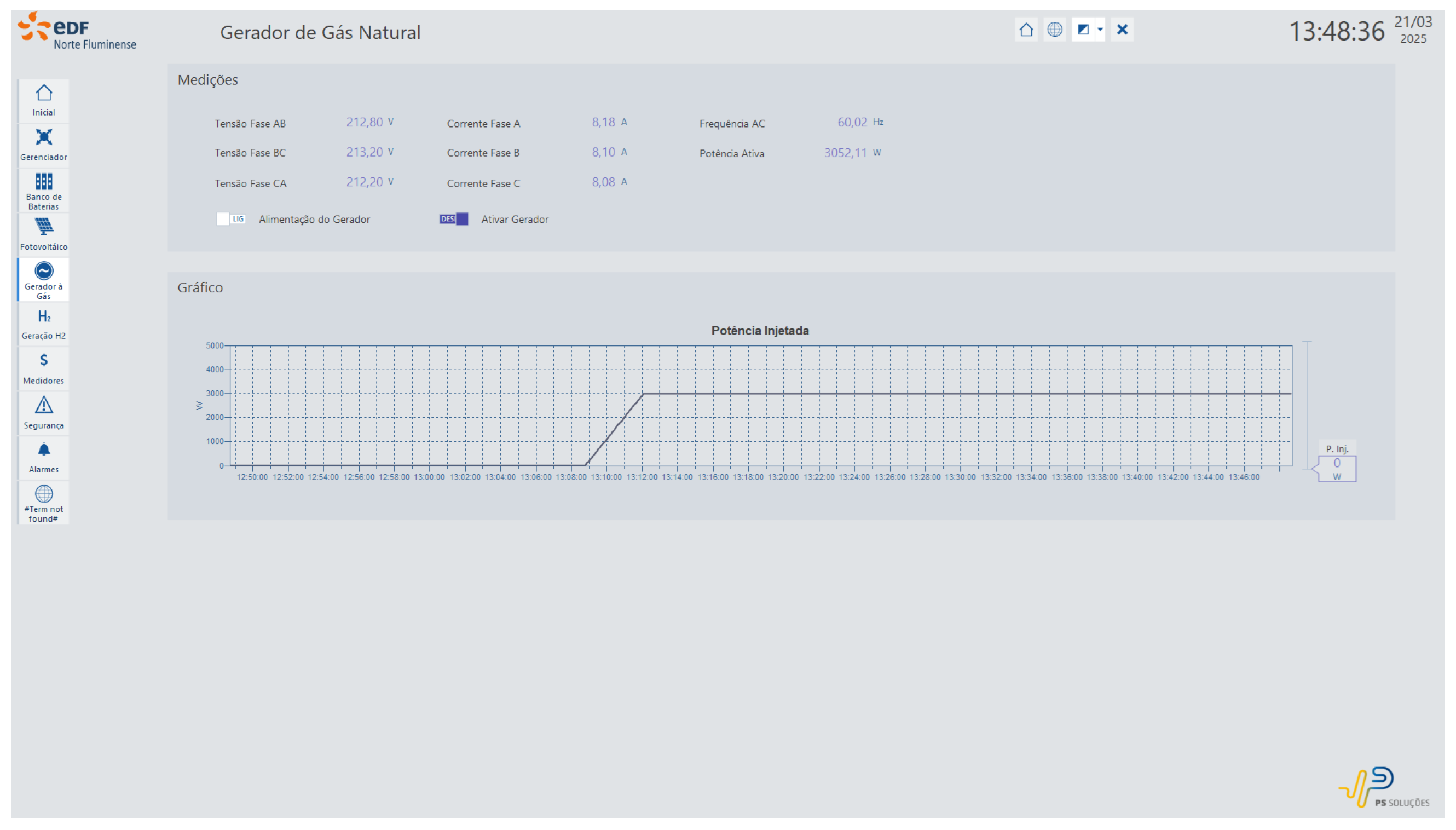
The LPG generator, adapted with a rectifier and inverter to operate in parallel with the grid, was tested with power limited to 3 kW. During operation, it was possible to gradually reduce power consumption from the utility as the generator’s output increased. The gas line and exhaust system operated normally and were monitored by safety sensors integrated into the supervisory system.
Figure 15 shows the supervisory interface during the generator’s operation period, highlighting the progressive increase in injected power up to the configured 3 kW limit. Also displayed are the current, voltage, and active power values delivered to the microgrid bus.
3.6. PEM Electrolyzer Operation
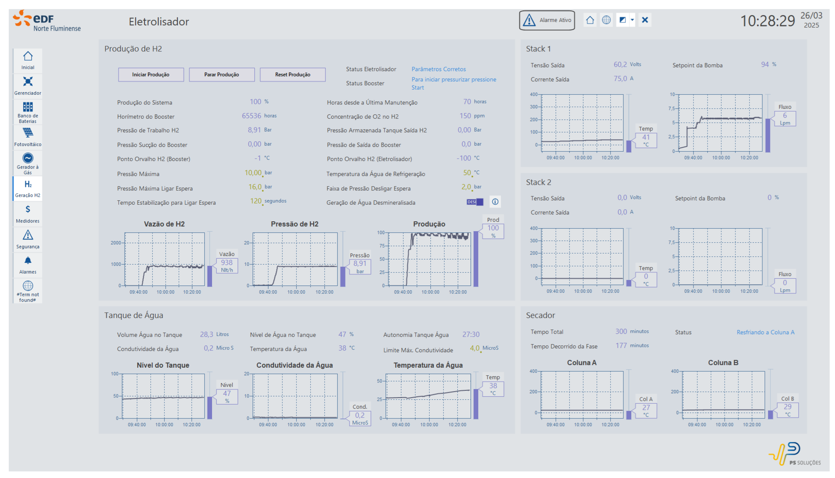
The PEM electrolyzer operated for 50 min under nominal conditions, with all parameters remotely controlled and monitored via the Elipse E3 supervisory system interface.
Figure 16 displays the dedicated electrolyzer screen within the supervisory system, where essential process variables for electrolysis operation can be observed and controlled. Among the monitored data are the stack voltage and current, hydrogen outlet pressure, H
2 production flow rate, and O
2 concentration level. Additionally, parameters associated with auxiliary systems were recorded, such as water conductivity, tank level and temperature, outlet pressure at the booster, and the activation status of the demineralization process. The system demonstrated stable performance throughout the operation, with values remaining within the design specifications, confirming the reliability of the integration between the equipment and the control platform.
3.7. Integrated Operation Validation
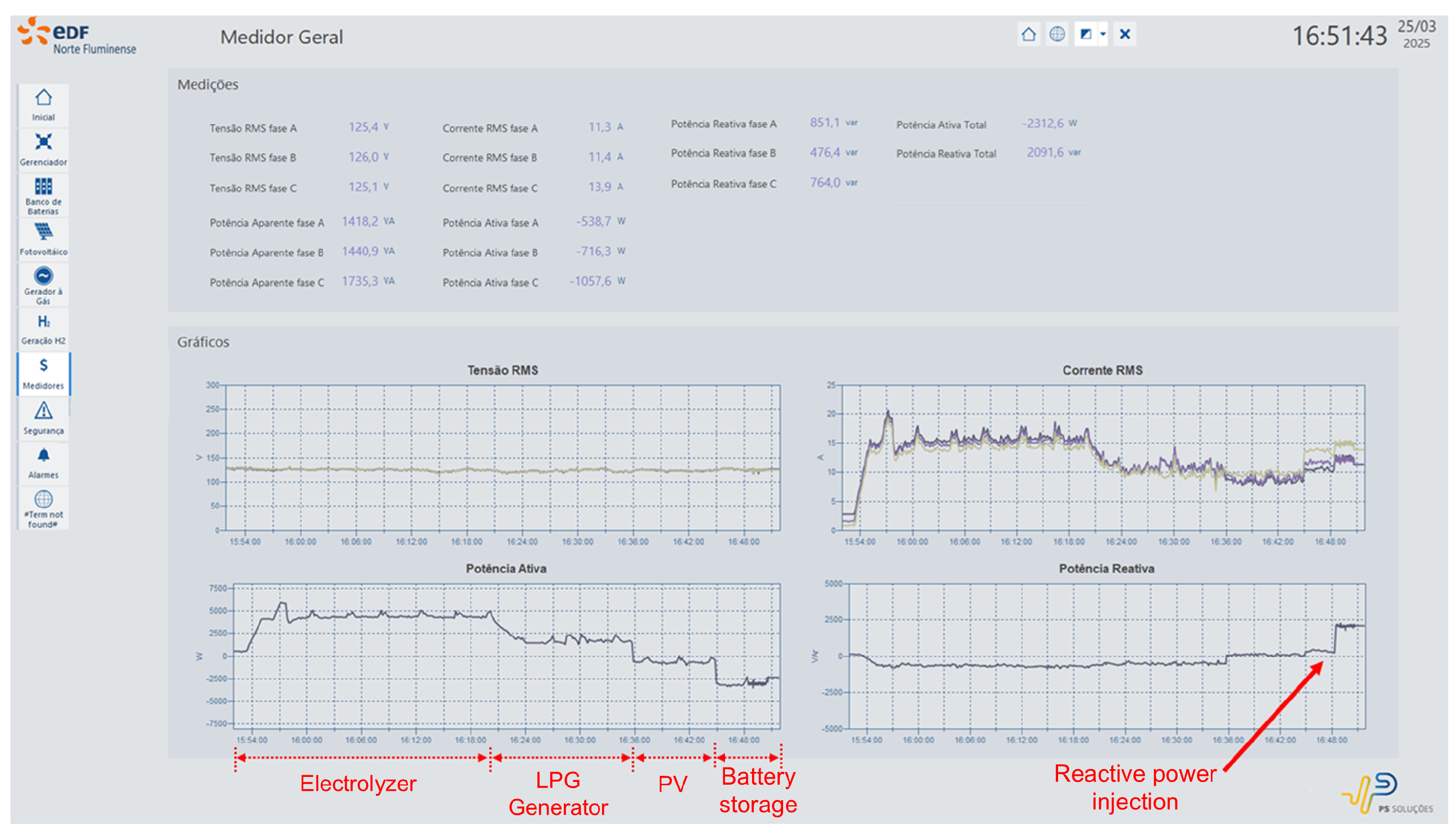
The integrated operation stage confirmed the coordinated performance of the subsystems, validating both the hybrid architecture and the supervisory system’s functionality under dynamic generation and demand scenarios. Initially, only the electrolyzer was activated, operating at approximately 67% of its capacity, which corresponds to a consumption of around 4.7 kW, fully supplied by the utility. After 28 min, the gas generator was started and its output was progressively increased until it reached 3 kW. Consequently, the power drawn from the utility was reduced to approximately 1.7 kW.
Figure 17 shows the supervisory system screen associated with the multimeter at the point of common coupling with the utility, enabling real-time visualization of the skid’s energy exchanges.
Subsequently, the photovoltaic system began injecting 2.5 kW, making the skid self-sufficient for the electrolyzer’s load. As a result, the energy surplus began to be exported to the grid, as evidenced by the inversion of the active power signal, with approximately 800 W being fed back to the utility. Finally, the battery storage system was activated in discharge mode, injecting about 2.6 kW into the microgrid. With this additional contribution, the exported surplus reached approximately 2.3 kW. In the final minutes of the test, the system also began injecting inductive reactive power, with measurements of approximately 1.9 kVar, demonstrating its capability for dynamic reactive power control.
These results not only demonstrate the functional integration of generation, storage, and conversion assets but also highlight the benefits of the system’s modular architecture. Modularity is a core design principle of the proposed skid, enabling scalability, flexible integration, and customization for different deployment contexts.
Each compartment operates as an independent unit equipped with its own sensing, control, and communication infrastructure. This decoupling allows for straightforward expansion or reconfiguration of the system, as components can be added or replaced according to application-specific needs. Standardized communication protocols such as TCP/IP and Modbus further simplify integration and support interoperability across the different subsystems.
In the current deployment at a thermoelectric power plant, modularity has enabled the incorporation of a cogeneration source—an LPG generator used to simulate thermal energy recovery. Future expansions may include additional assets such as fuel cells, allowing stored hydrogen to be converted back into electricity during periods of low renewable generation or peak demand.
Beyond technical benefits, modularity also enhances commercial viability by allowing the system to be delivered in predefined power blocks. Multiple skids can be connected in parallel or cascade to scale the system according to a client’s energy production capacity or hydrogen demand, without requiring full redesign.
Nevertheless, as the number of modules increases, especially in large-scale deployments, system-level coordination becomes more complex. While local control ensures fault isolation and rapid responsiveness, global energy management requires hierarchical architectures capable of balancing loads, managing distributed resources, and synchronizing operations across heterogeneous assets.
3.8. Cost Analysis
A preliminary cost analysis was conducted to estimate the production cost of green hydrogen, assuming that all electricity would be supplied by the photovoltaic (PV) system integrated into the skid. The calculation considered the levelized cost of electricity (LCOE) based on local resource and system parameters, as well as the levelized cost of hydrogen (LCOH) over the system’s lifetime. The adopted parameters are summarized in
Table 1. The resulting LCOE was estimated at USD 0.067 per kWh. Incorporating this value into the hydrogen production scenario, the levelized cost of hydrogen (LCOH) was determined to be approximately USD 23.10 per kg of H
2. This estimate includes capital costs, operational expenditures, and financial factors over a 25-year project horizon. The breakdown of the LCOH revealed that CAPEX depreciation contributed around USD 6.59 per kg H
2, electricity costs accounted for USD 3.69 per kg H
2, OPEX contributed USD 4.95 per kg H
2, and the cost of capital added USD 8.68 per kg H
2. These results provide a preliminary benchmark for future techno-economic assessments and indicate that further optimization of the system design and operating strategy could reduce the production cost in subsequent phases of the project. It is important to note that the current estimate does not include tax reductions or public incentives commonly available for green hydrogen projects, which could substantially lower the final production cost if applied.
3.9. CO2 Emissions Avoided
The environmental benefits of implementing on-site green hydrogen production were estimated by evaluating two main impact categories: the reduction in hydrogen transportation-related emissions and the partial substitution of natural gas in thermoelectric processes.
First, the local production of hydrogen eliminates the need for truck-based deliveries. In 2024 alone, four hydrogen delivery trips were made, each covering a round-trip distance of 1386 km, totaling 5544 km traveled. This transportation resulted in an estimated diesel consumption of 1630.58 L. By producing hydrogen locally, these deliveries are avoided, leading to an estimated reduction of approximately 3.78 tCO2e of greenhouse gas emissions, along with 0.52 tCO2 of biogenic CO2, corresponding to a total of around 27.86 tCO2 of CO2 emissions avoided annually.
Second, in terms of fuel displacement, the thermoelectric plant currently consumes about 3,000,000 m3 of natural gas per day under standard operating conditions. Scaling the hydrogen production system to allow for a 15% energy substitution through hydrogen blending would reduce natural gas consumption by 450,000 m3 per day, based on lower heating value equivalence. Considering an emission factor of approximately 1.9 kg CO2 per m3 of natural gas, this would result in a reduction of 855 tons of CO2 per day, equivalent to roughly 312,000 tons of CO2 avoided annually.
These demonstrate the substantial environmental benefits achievable through green hydrogen integration, both by displacing fossil fuel use within thermoelectric processes and by avoiding emissions associated with conventional hydrogen distribution logistics.
4. Conclusions
The experimental results obtained in this study confirm the technical feasibility of the modular microgrid developed for hydrogen production, validating both the individual and integrated operation of its subsystems within a controlled industrial environment. The integration of battery storage, cogeneration, electrolysis, and photovoltaic generation, coordinated by an autonomous supervisory system, demonstrated robust and reliable performance.
The proposed architecture enabled the stable production of high-purity hydrogen while ensuring efficient control of key electrical parameters such as active and reactive power and harmonic distortion, thereby enhancing the microgrid’s overall functionality. The system’s ability to operate in islanded mode, export surplus energy to the utility grid, and respond in real time to economic variables further underscores its technological maturity and readiness for broader deployment.
The hydrogen produced meets purity standards and can be used directly in plant operations, such as in the hydrogen-cooled generators, thereby reducing reliance on external suppliers. Moreover, a relevant long-term strategy identified in this study involves blending hydrogen with natural gas in the thermoelectric combustion process. This approach would reduce fossil fuel dependency while preserving operational continuity, resulting in significant greenhouse gas emission reductions. Based on emission factor projections, such integration could mitigate up to 312,000 tons of CO2 annually when applied at scale.
To quantify the economic viability of hydrogen production, a preliminary levelized cost analysis was performed. Assuming full photovoltaic supply, the resulting levelized cost of hydrogen (LCOH) was estimated at USD 23.10/kg H2, accounting for capital expenditures, operational costs, electricity input, and financial parameters over 25 years. While not yet competitive with conventional hydrogen sources, this figure provides a reference for future optimization and scale-up strategies.
Complementing the technical and environmental contributions, a blockchain-based data logging system was also integrated into the microgrid’s supervisory platform. This digital layer enables the traceability of renewable electricity usage during electrolysis, ensuring transparency and credibility for the generation of green hydrogen certificates and potential carbon credit markets. This innovation supports emerging regulatory frameworks and reinforces the project’s alignment with sustainable and decentralized energy paradigms.
Beyond achieving technical and regulatory goals, the project offers a replicable platform for other industrial facilities seeking to integrate hydrogen production, smart microgrids, and advanced control technologies. The results reinforce hydrogen’s strategic role as an energy vector in the transition toward a cleaner energy matrix and position the proposed solution as a promising model of applied innovation for the energy sector.
Although promising, some limitations must be acknowledged. The current system was implemented as a pilot-scale demonstrator, and its scalability to multi-skid or high-demand scenarios will require adaptations in control architecture, communication infrastructure, and system resilience. Furthermore, long-term economic assessments—including maintenance costs, stack durability, and return on investment—remain to be explored under real operating cycles.
In summary, this work provides experimental evidence of a flexible and replicable platform for green hydrogen production, integrating renewable generation, storage, and digital control technologies. The modular, scalable, and traceable nature of the proposed system positions it as a viable solution for industrial decarbonization, contributing to the broader transition toward a clean, resilient, and data-driven energy future.
Limitations and Future Perspectives
While the results confirm the technical and operational feasibility of the proposed system, certain limitations must be acknowledged to contextualize the findings and guide future research and implementation efforts.
A key limitation concerns the scalability of the system. In its current configuration, the skid was designed as a small-scale pilot. Replicating this solution in medium- or large-scale projects—incorporating multiple energy sources, diversified load profiles, and additional electrolyzers—will require technological adaptations, infrastructure reinforcement, and further research to address challenges related to system stability, safety, and distributed control.
Additionally, although the system met the defined technical performance criteria, medium- and long-term economic factors—such as maintenance costs, component longevity, and return on investment (ROI)—remain open questions that should be systematically evaluated in future work.
These limitations do not diminish the relevance or innovative nature of the present study. On the contrary, they highlight essential areas for future investigation, supporting the continued maturation of the technology and its application in more complex industrial environments.
Furthermore, there is significant potential to optimize the skid through the implementation of advanced energy management algorithms and the integration of machine learning techniques. These approaches could improve the system’s ability to predict load variations, optimize the dispatch of energy resources, and enhance the overall efficiency and reliability of microgrid operations. By enabling adaptive control strategies based on real-time data and historical performance patterns, such innovations would further increase the system’s scalability and economic viability, reinforcing its relevance in more demanding industrial scenarios.


 ,
, 


