

A Review of Recent Research on Flow and Heat Transfer Analysis in Additively Manufactured Transpiration Cooling for Gas Turbines


Abstract
1. Introduction
1.1. Importance of Advanced Cooling Technology for Gas Turbines
1.2. Evolution from Traditional to Transpiration Cooling

1.3. Framework and Objectives
2. Literature Review of Transpiration Cooling
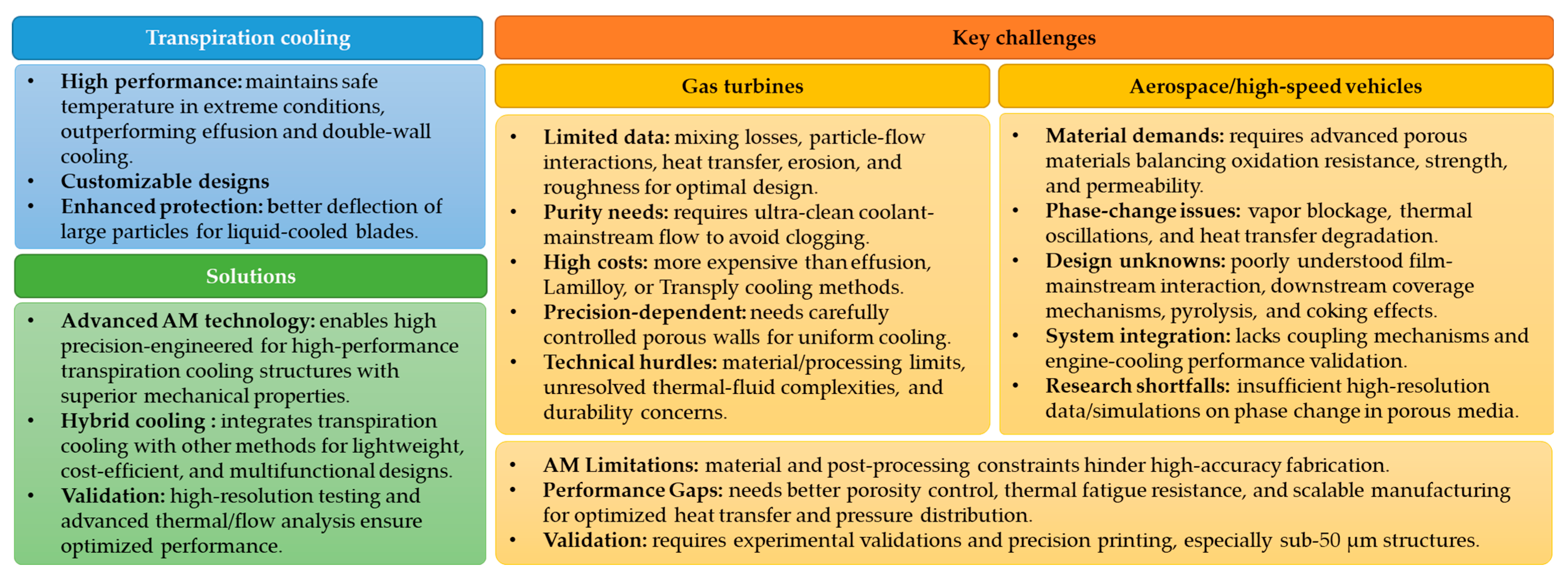
2.1. Research Progress and Challenges of Transpiration Cooling
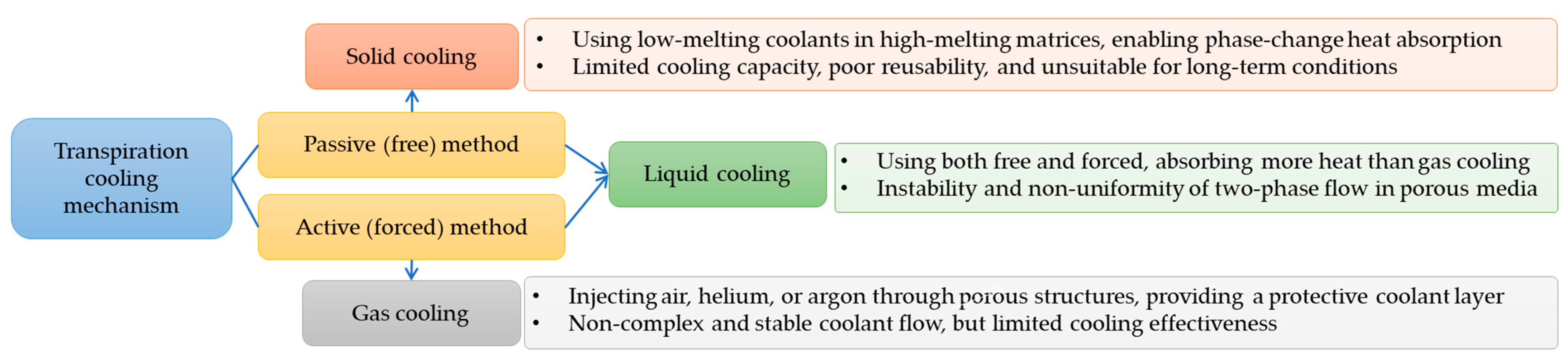
2.2. Classification of Transpiration Cooling
3. Additive Manufacturing for Transpiration Cooling
3.1. Traditional Manufacturing for Transpiration Cooling
3.2. Additive Manufacturing Techniques for Transpiration Cooling
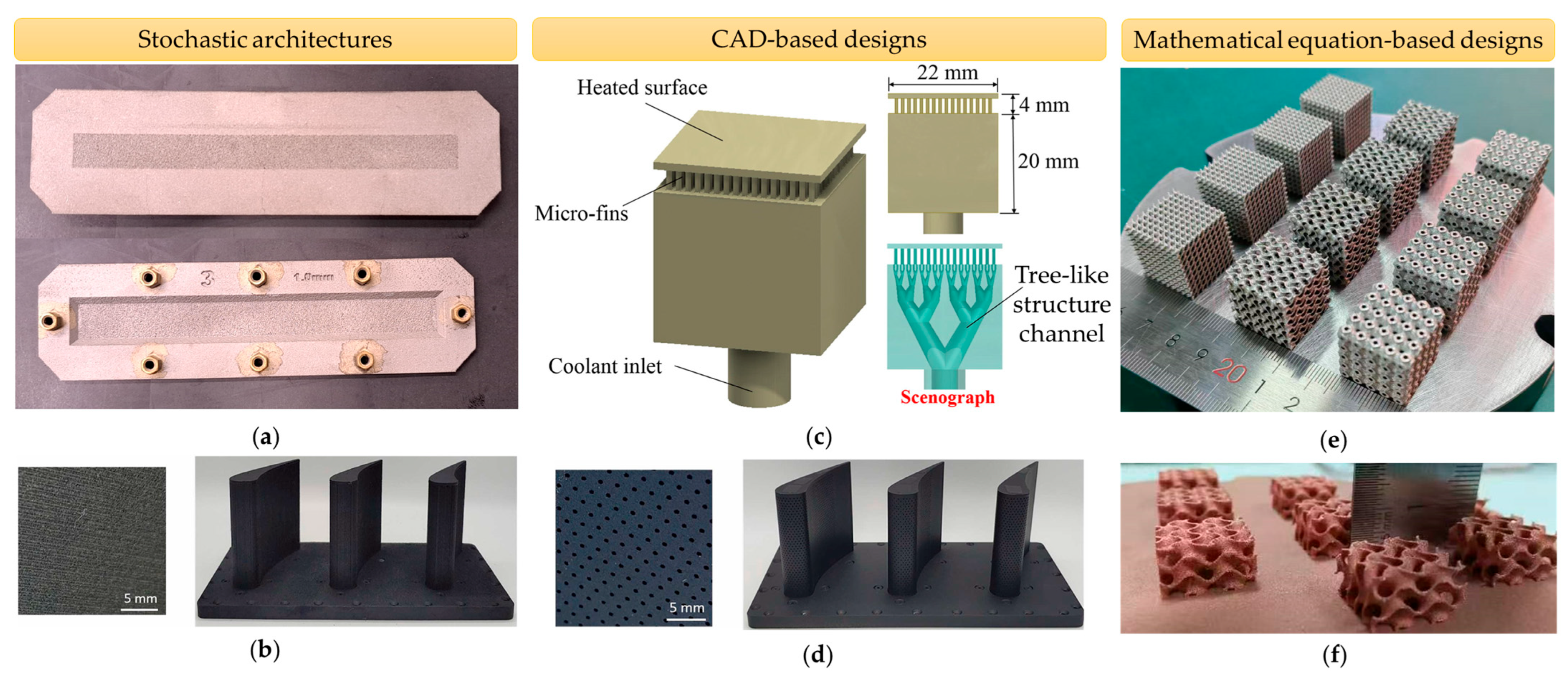
3.3. Additive Manufacturing-Fabricated Advanced Transpiration Cooling Structures
4. Flow and Heat Transfer Analysis
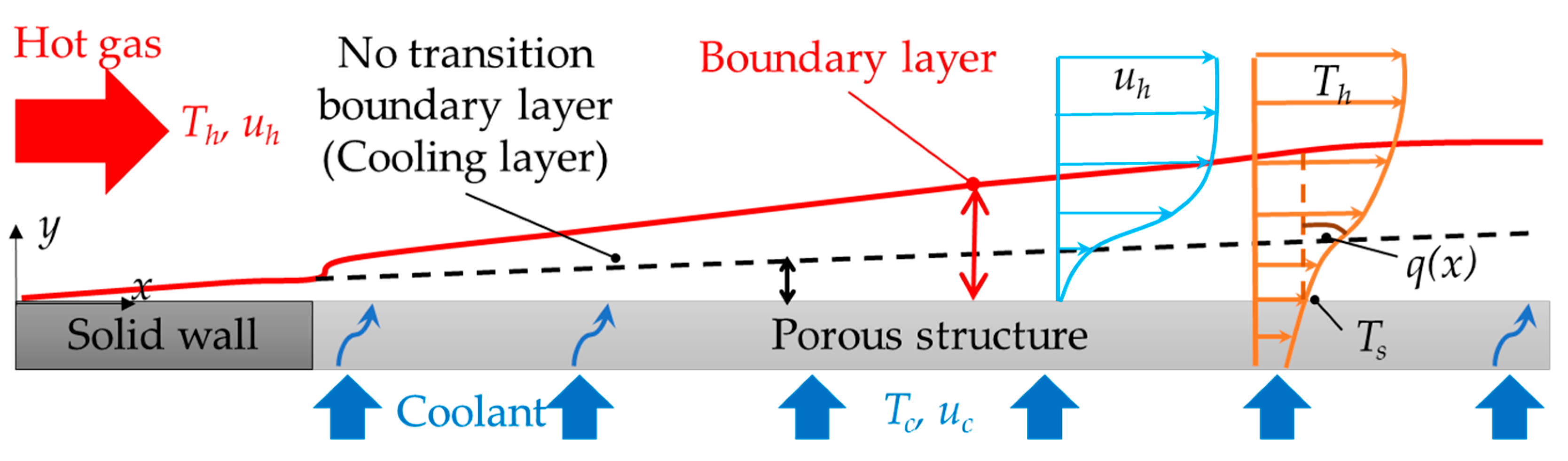
4.1. Heat Transfer Mechanism
4.2. Related Parameters
4.3. Experimental Research
4.3.1. Experimental Setup and Measurement Method
4.3.2. Experimental Studies on AM-Fabricated Random-Pore Porous Structures
4.3.3. Experimental Investigations on AM-Fabricated Non-Stochastic Structures
4.4. Numerical Simulations
4.5. Effect of Studied Conditions
4.6. Effect of Structural Designs
4.6.1. Influence of Porosity
4.6.2. Influence of Topology
4.7. Optimization Studies
4.7.1. Topology Optimization with Lattices
4.7.2. Machine Learning and Convolution-Based Modeling
4.7.3. Surrogate Modeling and Evolutionary Algorithms
4.7.4. Gradient Porosity and Response Surface Methods
5. Challenges and Future Directions
5.1. Additive Manufacturing Challenges and Innovations
5.2. Pore Blockage and Mitigation Strategies
5.3. Mechanical Integrity and Enhanced Design Approaches
5.4. Experimental and Simulation Challenges with Future Methodologies
5.5. Integrated Optimization Approaches
6. Conclusions
- AM-fabricated perforated transpiration-cooled plates achieve 10–100% higher cooling effectiveness than traditional film cooling, though dimensional inaccuracies around 4–77% porosity shrinkage in 0.06–0.5 mm holes and 10% ultimate tensile strength reductions in AM models present reliability concerns. While the integration of CAD-based lattice structures with transpiration cooling slightly reduces cooling performance, it mitigates pore blockage effects and provides superior structural support, overcoming the mechanical limitations of pure transpiration cooling.
- Advanced AM techniques allow the precise fabrication of complex and deterministic structures, such as TPMS and biomimetic designs. These cooling models enhance adiabatic cooling effectiveness by up to five times compared to conventional film cooling. Gradient porosity/thickness of such structures balances thermal-mechanical properties, mitigates jet lift-off, and provides flow uniformity, improving temperature distributions on the surface.
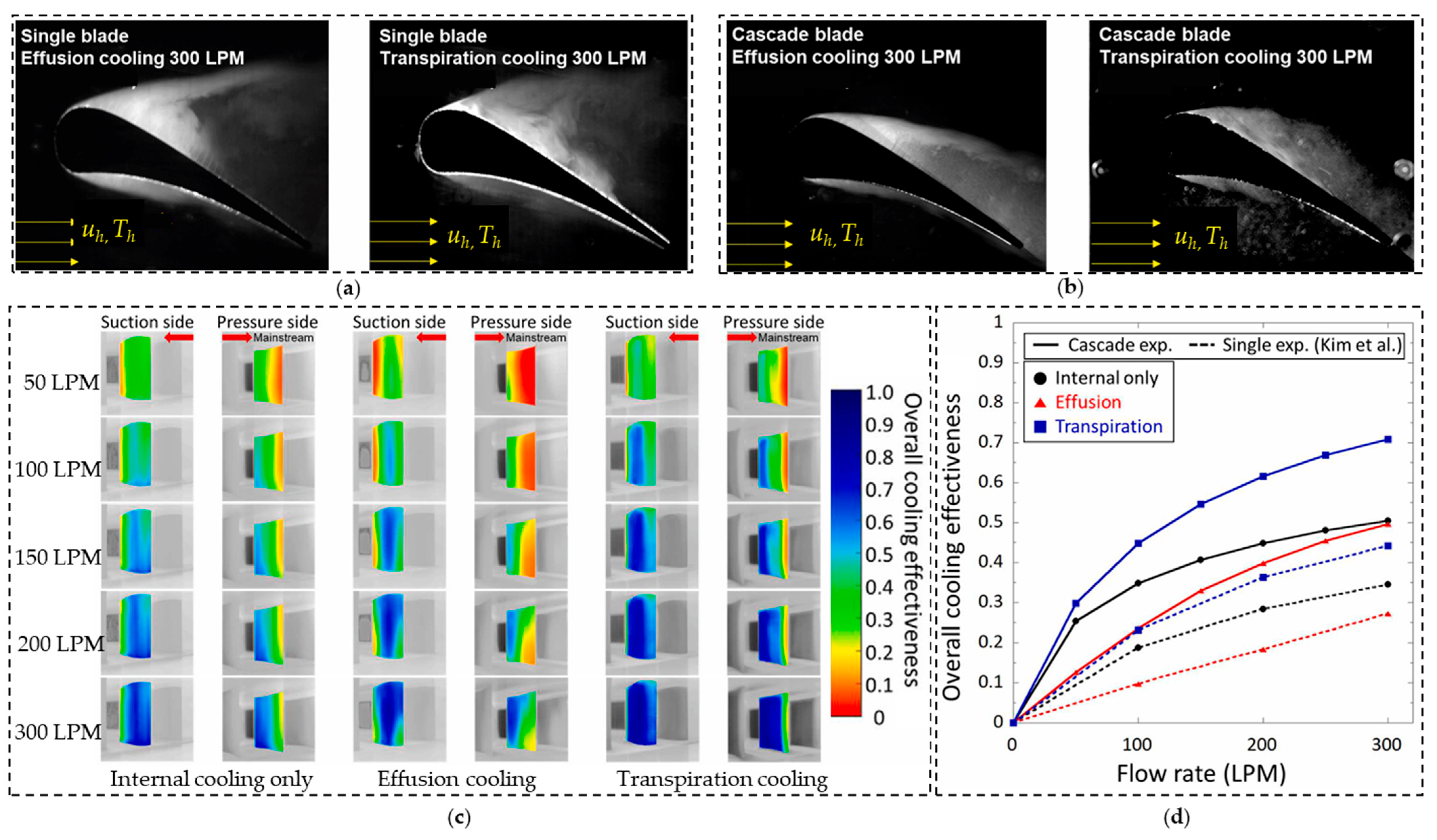
- Transpiration cooling forms a more stable boundary layer on the hot wall than effusion cooling, particularly on the blade surface, but excessive coolant supply can degrade performance due to hot gas entrainment. Precise control of the porosity and coolant supply is therefore required to avoid coolant leakages, non-uniform coolant distributions, and uneven temperature/pressure patterns.
- Current AM technology introduces 15% hole size reductions from surface roughness and around 15% permeability deviations from CAD models, compounded by unresolved high-temperature material limitations, with only direct metal laser sintering (DMLS)-fabricated oxide coatings demonstrating reliable stability.
- AI-driven optimization, such as artificial neural networks (ANNs) combined with multi-objective genetic algorithms (MOGAs), topology optimization, and hybrid cooling, such as discrete film holes with transpiration cooling, also offer balanced thermal-structural solutions. Nonetheless, their implementation requires advanced experimental diagnostics and high-fidelity multiphysics modeling to fully validate these innovative cooling systems for practical implementation.
Author Contributions
Funding
Data Availability Statement
Acknowledgments
Conflicts of Interest
Nomenclature
| Aeff | Coolant covered area on the hot-side surface (m2) |
| Ah | Cross-sectional area of the mainstream channel (m2) |
| Aint | Internal area of the solid–fluid interface inside the specimens (m2) |
| Aout | Outlet area of the coolant at the outer surface (m2) |
| Apore | Total cross-sectional area of transpiration cooling topology (m2) |
| Bi | Biot number (-) |
| BR | Blowing ratio (-) |
| CD, CF | Discharge and skin-friction coefficients (-) |
| CF | Inertial resistance coefficient (1/m) |
| Ch | Circumference of the mainstream channel (m) |
| cp | Heat capacity of the fluid (J/(kg·K)) |
| dc, dh | Hydraulic diameter of coolant and mainstream channels (m) |
| d, dpore | Diameter of micro hole and porous-media pore (m) |
| F | Injection ratio (-) |
| F | External force in Navier–Stokes equation (N/m3) |
| h | Convective heat transfer coefficient (W/(m2K)) |
| k | Turbulence kinetic energy in turbulence model (m2/s2) |
| K | Permeability (m2) |
| keff | Effectiveness thermal conductivity of porous media (W/(m·K)) |
| kf, ks | Thermal conductivity of fluid and solid (W/(m·K)) |
| L | Unit cell size (m) |
| Lc | Characteristic length of the transpiration cooling design (m) |
| Mass flow rate of coolant and mainstream (kg/s) | |
| Ma | Mach number (-) |
| MFR | Mass flow ratio of coolant to mainstream (-) |
| Nu | Nusselt number (-) |
| Nu/Nu0 | Normalized Nusselt number for heat transfer enhancement evaluation (-) |
| p | Pressure field (Pa) |
| pt,in, pt,out | Total pressure of the coolant inlet and outlet (Pa) |
| q(x) | Heat flux (W/m2) |
| Qtot | Total heat transfer (W) |
| Rint, Rout | Internal and outlet area ratios (-) |
| Rec, Reh | Reynolds number of coolant and mainstream (-) |
| Sm | Mass source term (N/m3) |
| Sv | Specific surface area (1/m) |
| t | Thickness (m) |
| T* | Non-dimensional temperature (-) |
| Tc, Th, Ts | Coolant, mainstream and surface temperatures (K) |
| Tflu, Tsol | Temperature of fluid and solid (K) |
| u | Velocity vector (m/s) |
| uc, uh, uD | Coolant, mainstream and Darcy velocities (m/s) |
| Volumetric flow rate Volumetric flow rate (liters per minute: LPM) | |
| Vdes | Design volume from CAD models (m3) |
| Vsol | Volume of solid domain with identical dimension (m3) |
| vc | Average velocity of coolant flow in the film hole or pore (m/s) |
| x, y, z | Cartesian coordinate (-) |
| Greek letters | |
| γ | Plugging probability (-) |
| ε | Turbulent dissipation rate (m2/s3) |
| ζPt | Total pressure loss coefficient (-) |
| ηa, ηo | Adiabatic and overall cooling effectiveness (-) |
| μ | Dynamic viscosity of fluid (kg/(m·s) |
| ρc, ρh | Fluid density of coolant and mainstream (kg/s) |
| Shear stress (Pa) | |
| φ | Porosity (%) |
| φdes, φact | Design and actual porosities (%) |
| ω | Specific dissipation rate in turbulence model (1/s) |
| Abbreviations | |
| ANN | Artificial neural network |
| AM | Additive manufacturing |
| CAD | Computer-aided design |
| CCD | Charged-coupled device |
| CFD | Computational fluid dynamics |
| CMC | Ceramic matrix composite |
| CRVP | Counter-rotating vortex |
| CT | Computed tomography |
| DLD | Direct laser deposition |
| DMLS | Direct metal laser sintering |
| EOS | Electro Optical Systems |
| FDM | Fused deposit modeling |
| GA | Genetic algorithm |
| IR | Infrared thermography |
| IWP | I-graph and wrapped package |
| LES | Large eddy simulation |
| LBM | Lattice Boltzmann method |
| LTNE | Local thermal non-equilibrium |
| MIM | Metal powder injection molding |
| MOGA | Multi-objective genetic algorithms |
| NASA | National Aeronautics and Space Administration |
| NS | Navier-Stokes |
| NSGA-II | Non-dominated sorting genetic algorithm-II |
| OH-PLIF | Hydroxyl radical |
| PVD | Physical vapor deposit |
| PIV | Particle image velocimetry |
| PS | Pressure side of turbine blades |
| PSP | Pressure-sensitive paint |
| RANS | Reynolds-averaged Navier–Stokes |
| SLA | Stereolithography |
| SLM | Selective laser melting |
| SS | Suction side of turbine blades |
| TE | Trailing edge |
| TBC | Thermal barrier coating |
| TIT | Turbine inlet temperature |
| TKE | Turbulence kinetic energy |
| TLC | Transient liquid crystal thermography |
| TPMS | Triply periodic minimal surface |
| UTS | Ultimate tensile strength (Pa) |
References
- Perepezko, J.H. The Hotter the Engine, the Better. Science 2009, 326, 1068–1069. [Google Scholar] [CrossRef]
- Dutta, S.; Kaur, I.; Singh, P. Review of Film Cooling in Gas Turbines with an Emphasis on Additive Manufacturing-Based Design Evolutions. Energies 2022, 15, 6968. [Google Scholar] [CrossRef]
- Ishikawa, M.; Komori, T.; Terauchi, M.; Yasuraoka, J. Development of High Efficiency Gas Turbine Combined Cycle. Tech. Rev. Mitsubishi Heavy Ind. 2008, 45, 15–17. [Google Scholar]
- Hada, S.; Tsukagoshi, K.; Masada, J.; Ito, E. Test Results of the World’s First 1600 °C J-Series Gas Turbine. Mitsubishi Heavy Ind. Tech. Rev. 2012, 49, 18–23. [Google Scholar]
- Wang, W.; Yan, Y.; Zhou, Y.; Cui, J. Review of Advanced Effusive Cooling for Gas Turbine Blades. Energies 2022, 15, 8568. [Google Scholar] [CrossRef]
- Han, J.-C.; Dutta, S.; Ekkad, S. Gas Turbine Heat Transfer and Cooling Technology, 2nd ed.; CRC Press: Boca Raton, FL, USA, 2012; ISBN 9780429107115. [Google Scholar]
- Clarke, D.R.; Oechsner, M.; Padture, N.P. Thermal-Barrier Coatings for More Efficient Gas-Turbine Engines. MRS Bull. 2012, 37, 891–898. [Google Scholar] [CrossRef]
- Li, Y.; Rao, Y.; Wang, D.; Zhang, P.; Wu, X. Heat Transfer and Pressure Loss of Turbulent Flow in Channels with Miniature Structured Ribs on One Wall. Int. J. Heat Mass Transf. 2019, 131, 584–593. [Google Scholar] [CrossRef]
- Liang, C.; Rao, Y. Computational Analysis of Rotating Effects on Heat Transfer and Pressure Loss of Turbulent Flow in Detached Pin Fin Arrays with Various Clearances. ASME J. Heat Transf. 2020, 142, 121803. [Google Scholar] [CrossRef]
- Rao, Y.; Feng, Y.; Li, B.; Weigand, B. Experimental and Numerical Study of Heat Transfer and Flow Friction in Channels With Dimples of Different Shapes. J. Heat Transfer 2015, 137, 031901. [Google Scholar] [CrossRef]
- YERANEE, K.; RAO, Y. A Review of Recent Studies on Rotating Internal Cooling for Gas Turbine Blades. Chinese J. Aeronaut. 2021, 34, 85–113. [Google Scholar] [CrossRef]
- Babji, G.; Pujari, A.K. Flow and Heat Transfer Studies of Multijet Impingement Cooling for Different Configurations: A Review. Heat Transf. 2022, 52, 1604–1672. [Google Scholar] [CrossRef]
- Ahn, J. Large Eddy Simulation of Film Cooling: A Review. Energies 2022, 15, 8876. [Google Scholar] [CrossRef]
- Nealy, D.A.; Reider, S.B. Evaluation of Laminated Porous Wall Materials for Combustor Liner Cooling. J. Eng. Gas Turbines Power 1980, 102, 268–276. [Google Scholar] [CrossRef]
- Wassell, A.B.; Bhangu, J.K. The Development and Application of Improved Combustor Wall Cooling Techniques. In Turbo Expo: Power for Land, Sea, and Air; American Society of Mechanical Engineers: New York, NY, USA, 1980; pp. 1–10. [Google Scholar]
- Murray, A.V.; Ireland, P.T.; Romero, E. Experimental and Computational Methods for the Evaluation of Double-Wall, Effusion Cooling Systems. J. Turbomach. 2020, 142, 111003. [Google Scholar] [CrossRef]
- Li, W.; Lu, X.; Li, X.; Ren, J.; Jiang, H. On Improving Full-Coverage Effusion Cooling Efficiency by Varying Cooling Arrangements and Wall Thickness in Double Wall Cooling Application. J. Heat Transfer 2019, 141, 042201. [Google Scholar] [CrossRef]
- Yeranee, K.; Rao, Y.; Xu, C.; Xie, J.; Zhang, Y. Conjugate Heat Transfer and Fluid Flow Analysis on Printable Double-Wall Effusion Cooling with Internal Topology-Optimized TPMS Structures. Therm. Sci. Eng. Prog. 2024, 55, 102939. [Google Scholar] [CrossRef]
- Rao, Y.; Liu, Y.; Wan, C. Multiple-Jet Impingement Heat Transfer in Double-Wall Cooling Structures with Pin Fins and Effusion Holes. Int. J. Therm. Sci. 2018, 133, 106–119. [Google Scholar] [CrossRef]
- Skamniotis, C.; Cocks, A.C.F. Minimising Stresses in Double Wall Transpiration Cooled Components for High Temperature Applications. Int. J. Mech. Sci. 2021, 189, 105983. [Google Scholar] [CrossRef]
- Skamniotis, C.; Courtis, M.; Cocks, A.C.F. Multiscale Analysis of Thermomechanical Stresses in Double Wall Transpiration Cooling Systems for Gas Turbine Blades. Int. J. Mech. Sci. 2021, 207, 106657. [Google Scholar] [CrossRef]
- Skamniotis, C.; Cocks, A.C.F. Designing against Severe Stresses at Compound Cooling Holes of Double Wall Transpiration Cooled Engine Components. Aerosp. Sci. Technol. 2021, 116, 106856. [Google Scholar] [CrossRef]
- Courtis, M.; Skamniotis, C.; Cocks, A.; Ireland, P. Coupled Aerothermal-Mechanical Analysis in Single Crystal Double Wall Transpiration Cooled Gas Turbine Blades with a Large Film Hole Density. Appl. Therm. Eng. 2023, 219, 119329. [Google Scholar] [CrossRef]
- Liang, C.; Rao, Y.; Luo, J.; Luo, X. Experimental and Numerical Study of Turbulent Flow and Heat Transfer in a Wedge-Shaped Channel with Guiding Pin Fins for Turbine Blade Trailing Edge Cooling. Int. J. Heat Mass Transf. 2021, 178, 121590. [Google Scholar] [CrossRef]
- Ma, H.; Sun, H.; Fu, H.; Luan, Y.; Sun, T.; Zunino, P. Numerical Investigation on Transpiration Cooling Performance of Turbine Blades with Non-Uniform Porosity. Appl. Therm. Eng. 2023, 235, 121394. [Google Scholar] [CrossRef]
- Jiang, P.X.; Huang, G.; Zhu, Y.; Liao, Z.; Huang, Z. Experimental Investigation of Combined Transpiration and Film Cooling for Sintered Metal Porous Struts. Int. J. Heat Mass Transf. 2017, 108, 232–243. [Google Scholar] [CrossRef]
- Lv, Y.; Liu, T.; Huang, X.; He, F.; Tang, L.; Zhou, J.; Wang, J. Numerical Investigation and Optimization of Flat Plate Transpiration-Film Combined Cooling Structure. Int. J. Therm. Sci. 2022, 179, 107673. [Google Scholar] [CrossRef]
- Munk, D.J.; Selzer, M.; Seiler, H.; Ortelt, M.; Vio, G.A. Analysis of a Transpiration Cooled LOX/CH4 Rocket Thrust Chamber. Int. J. Heat Mass Transf. 2022, 182, 121986. [Google Scholar] [CrossRef]
- Steingrimsson, A.; Marsell, B.; Mankbadi, R.; Kapat, J. Towards Prediction of Transpiration Cooling. In Proceedings of the 48th AIAA Aerospace Sciences Meeting Including the New Horizons Forum and Aerospace Exposition, Orlando, FL, USA, 4–7 January 2010. [Google Scholar] [CrossRef]
- Kim, M.; Shin, D.H.; Lee, B.J.; Lee, J. Experimental and Numerical Investigation of Micro-Scale Effusion and Transpiration Air Cooling on Cascaded Turbine Blades. Case Stud. Therm. Eng. 2022, 32, 101892. [Google Scholar] [CrossRef]
- Song, K.D.; Choi, S.H.; Scotti, S.J. Transpiration Cooling Experiment for Scramjet Engine Combustion Chamber by High Heat Fluxes. J. Propuls. Power 2006, 22, 96–102. [Google Scholar] [CrossRef]
- Elnady, T.; Hassan, I.; Kadem, L.; Lucas, T. Cooling Effectiveness of Shaped Film Holes for Leading Edge. Exp. Therm. Fluid Sci. 2013, 44, 649–661. [Google Scholar] [CrossRef]
- Reimer, T.; Kuhn, M.; Gülhan, A.; Esser, B.; Sippel, M.; Foreest, A. Van Transpiration Cooling Tests of Porous Cmc in Hypersonic Flow. In Proceedings of the 17th AIAA International Space Planes and Hypersonic Systems and Technologies Conference, San Francisco, CA, USA, 11–14 April 2011; pp. 1–13. [Google Scholar] [CrossRef]
- Langener, T.; Von Wolfersdorf, J.; Steelant, J. Experimental Investigations on Transpiration Cooling for Scramjet Applications Using Different Coolants. AIAA J. 2011, 49, 1409–1419. [Google Scholar] [CrossRef]
- Kumar, C.S.; Pattamatta, A. Assessment of Heat Transfer Enhancement Using Metallic Porous Foam Configurations in Laminar Slot Jet Impingement: An Experimental Study. J. Heat Transfer 2018, 140, 022202. [Google Scholar] [CrossRef]
- Andrews, G.E.; Asere, A.A.; Mkpadi, M.C.; Tirmahi, A. Asme 1986 International Gas Turbine Conference Transpiration Cooling: Contribution of Film Cooling To the Overall Cooling Effectiveness. In Proceedings of the American Society of Mechanical Engineers (Paper), Dusseldorf, Germany, 8–12 June 1986; American Society of Mechanical Engineers: New York, NY, USA, 1986. [Google Scholar]
- Polezhaev, J. The Transpiration Cooling for Blades of High Temperatures Gas Turbine. Energy Convers. Manag. 1997, 38, 1123–1133. [Google Scholar] [CrossRef]
- Wang, Y.; Wang, L.; Zhou, Y.; Luo, Z.; Xie, W.; Liu, Q.; Peng, W.; Du, M. Research Progress on Transpiration Cooling Technology in Force-Thermal Concentrated Environments. Int. J. Heat Mass Transf. 2025, 236, 126262. [Google Scholar] [CrossRef]
- Raj, R.; Moskowitz, S. Transpiration Air Protected Turbine Blades—An Effective Concept To Achieve High Temperature and Erosion Resistance for Gas Turbines Operating in an Aggressive Environment; American Society of Mechanical Engineers: New York, NY, USA, 1978; pp. 1–11. [Google Scholar]
- Wadia, A.R. Advanced Combustor Linear Cooling Technology for Gas Turbines. Def. Sci. J. 1988, 38, 363–380. [Google Scholar] [CrossRef]
- Bunker, R.S. Gas Turbine Cooling: Moving from Macro to Micro Cooling; American Society of Mechanical Engineers: New York, NY, USA, 2013; Volume 3C, pp. 1–17. [Google Scholar] [CrossRef]
- Bunker, R.S. Evolution of Turbine Cooling; American Society of Mechanical Engineers: New York, NY, USA, 2017; Volume 1, pp. 1–26. [Google Scholar] [CrossRef]
- Xu, L.; Sun, Z.; Ruan, Q.; Xi, L.; Gao, J.; Li, Y. Development Trend of Cooling Technology for Turbine Blades at Super-High Temperature of above 2000 K. Energies 2023, 16, 668. [Google Scholar] [CrossRef]
- Mi, Q.; Yi, S.H.; Gang, D.D.; Lu, X.G.; Liu, X.L. Research Progress of Transpiration Cooling for Aircraft Thermal Protection. Appl. Therm. Eng. 2024, 236, 121360. [Google Scholar] [CrossRef]
- Zhang, S.; Li, X.; Zuo, J.; Qin, J.; Cheng, K.; Feng, Y.; Bao, W. Research Progress on Active Thermal Protection for Hypersonic Vehicles. Prog. Aerosp. Sci. 2020, 119, 100646. [Google Scholar] [CrossRef]
- Xu, R.; Cheng, Z.; Jiang, P. Fundamentals and Recent Progress of Additive Manufacturing-Assisted Porous Materials on Transpiration Cooling. J. Glob. Power Propuls. Soc. 2023, 2023, 19–48. [Google Scholar] [CrossRef]
- Weinbaum, S.; Wheeler, H.L. Heat Transfer in Sweat-Cooled Porous Metals. J. Appl. Phys. 1949, 20, 113–122. [Google Scholar] [CrossRef]
- Hald, H.; Ortelt, M.; Fischer, I.; Greuel, D. CMC Rocket Combustion Chamber with Effusion Cooling. In Proceedings of the 54th International Astronautical Congress of the International Astronautical Federation, the International Academy of Astronautics, and the International Institute of Space Law, Bremen, Germany, 29 September–3 October 2003; Volume 3, pp. 657–667. [Google Scholar] [CrossRef]
- Huang, Z.; Xiong, Y.B.; Liu, Y.Q.; Jiang, P.X.; Zhu, Y.H. Experimental Investigation of Full-Coverage Effusion Cooling through Perforated Flat Plates. Appl. Therm. Eng. 2015, 76, 76–85. [Google Scholar] [CrossRef]
- Wang, F.; Song, N.; Xia, X.; Chen, X. Experimental Investigation on Transpiration Cooling of Ammonium Carbonate in Porous Composite Structure at High-Temperature. Appl. Therm. Eng. 2024, 249, 123292. [Google Scholar] [CrossRef]
- Huang, G.; Min, Z.; Yang, L.; Jiang, P.X.; Chyu, M. Transpiration Cooling for Additive Manufactured Porous Plates with Partition Walls. Int. J. Heat Mass Transf. 2018, 124, 1076–1087. [Google Scholar] [CrossRef]
- Van Foreest, A.; Sippel, M.; Gülhan, A.; Esser, B.; Ambrosius, B.A.C.; Sudmeijer, K. Transpiration Cooling Using Liquid Water. J. Thermophys. Heat Transf. 2009, 23, 693–702. [Google Scholar] [CrossRef]
- Liu, Y.; Liu, T.; Ding, R.; He, F.; Wang, J. Experimental and Numerical Investigation of Transpiration Cooling with Gradient Porosity Layout for the Thermal Protection of Nose Cone. Aerosp. Sci. Technol. 2024, 149, 109140. [Google Scholar] [CrossRef]
- Huang, G.; Zhu, Y.; Liao, Z.; Ouyang, X.L.; Jiang, P.X. Experimental Investigation of Transpiration Cooling with Phase Change for Sintered Porous Plates. Int. J. Heat Mass Transf. 2017, 114, 1201–1213. [Google Scholar] [CrossRef]
- Glass, D.E. Ceramic Matrix Composite (CMC) Thermal Protection Systems (TPS) and Hot Structures for Hypersonic Vehicles. In Proceedings of the 15th AIAA International Space Planes and Hypersonic Systems and Technologies Conference, Dayton, Ohio, 28 April–1 May 2008; pp. 1–36. [Google Scholar] [CrossRef]
- Xu, G.; Liu, Y.; Luo, X.; Ma, J.; Li, H. Experimental Investigation of Transpiration Cooling for Sintered Woven Wire Mesh Structures. Int. J. Heat Mass Transf. 2015, 91, 898–907. [Google Scholar] [CrossRef]
- Gavalda Diaz, O.; Garcia Luna, G.; Liao, Z.; Axinte, D. The New Challenges of Machining Ceramic Matrix Composites (CMCs): Review of Surface Integrity. Int. J. Mach. Tools Manuf. 2019, 139, 24–36. [Google Scholar] [CrossRef]
- Ekkad, S.V.; Zapata, D.; Han, J.C. Film Effectiveness over a Flat Surface with Air and CO2 Injection through Compound Angle Holes Using a Transient Liquid Crystal Image Method. In Proceedings of the ASME 1995 International Gas Turbine and Aeroengine Congress and Exposition, Houston, TX, USA, 5–8 June 1995; p. 4. [Google Scholar] [CrossRef]
- Blakey-Milner, B.; Gradl, P.; Snedden, G.; Brooks, M.; Pitot, J.; Lopez, E.; Leary, M.; Berto, F.; du Plessis, A. Metal Additive Manufacturing in Aerospace: A Review. Mater. Des. 2021, 209, 110008. [Google Scholar] [CrossRef]
- Kamal, M.; Rizza, G. Design for Metal Additive Manufacturing for Aerospace Applications. In Additive Manufacturing for the Aerospace Industry; Elsevier Inc.: Amsterdam, The Netherlands, 2019; pp. 67–86. ISBN 9780128140635. [Google Scholar]
- Najmon, J.C.; Raeisi, S.; Tovar, A. Review of Additive Manufacturing Technologies and Applications in the Aerospace Industry. In Additive Manufacturing for the Aerospace Industry; Elsevier Inc.: Amsterdam, The Netherlands, 2019; pp. 7–31. ISBN 9780128140635. [Google Scholar]
- Tian, X.; Ye, W.; Xu, L.; Yang, A.; Huang, L.; Jin, S. Optimization Research on Laminated Cooling Structure for Gas Turbines: A Review. AIMS Energy 2025, 13, 354–401. [Google Scholar] [CrossRef]
- Li, R.; Liu, J.; Shi, Y.; Du, M.; Xie, Z. 316L Stainless Steel with Gradient Porosity Fabricated by Selective Laser Melting. J. Mater. Eng. Perform. 2010, 19, 666–671. [Google Scholar] [CrossRef]
- Cheng, Z.; Xu, R.; Jiang, P. Transpiration Cooling with Phase Change by Functionally Graded Porous Media. Int. J. Heat Mass Transf. 2023, 205, 123862. [Google Scholar] [CrossRef]
- Nguyentat, T.; Hayes, W.A.; Meland, T.O.; Veith, E.M.; Ellis, D.L. Fabrication of a Liquid Rocket Combustion Chamber Liner of Advanced Copper Alloy GRCop-84 via Formed Platelet Liner Technology. In Proceedings of the 42nd AIAA/ASME/SAE/ASEE Joint Propulsion Conference & Exhibit, Sacramento, CA, USA, 9–12 July 2006; Volume 10, pp. 8335–8344. [Google Scholar] [CrossRef]
- Traub, H.; Kube, J.; Jose, S.; Prasannakumar, A.; Hühne, C. Structural and Aerodynamic Characteristics of Micro-Perforated Porous Sheets for Laminar Flow Control. In Proceedings of the ASME 2024 Aerospace Structures, Structural Dynamics, and Materials Conference, SSDM 2024, Renton, WA, USA, 29 April–1 May 2024; American Society of Mechanical Engineers: New York, NY, USA, 2024; pp. 1–10. [Google Scholar]
- Yeranee, K.; Rao, Y.; Zuo, Q.; Xie, J. Thermal Performance Enhancement for Gas Turbine Blade Trailing Edge Cooling with Topology-Optimized Printable Diamond TPMS Lattice. Int. J. Heat Fluid Flow 2024, 110, 109649. [Google Scholar] [CrossRef]
- Sinha, A.; Swain, B.; Behera, A.; Mallick, P.; Samal, S.K.; Vishwanatha, H.M.; Behera, A. A Review on the Processing of Aero-Turbine Blade Using 3D Print Techniques. J. Manuf. Mater. Process. 2022, 6, 16. [Google Scholar] [CrossRef]
- Kaur, I.; Aider, Y.; Nithyanandam, K.; Singh, P. Thermal-Hydraulic Performance of Additively Manufactured Lattices for Gas Turbine Blade Trailing Edge Cooling. Appl. Therm. Eng. 2022, 211, 118461. [Google Scholar] [CrossRef]
- Wilson, J.M.; Piya, C.; Shin, Y.C.; Zhao, F.; Ramani, K. Remanufacturing of Turbine Blades by Laser Direct Deposition with Its Energy and Environmental Impact Analysis. J. Clean. Prod. 2014, 80, 170–178. [Google Scholar] [CrossRef]
- Kaplanskii, Y.Y.; Levashov, E.A.; Korotitskiy, A.V.; Loginov, P.A.; Sentyurina, Z.A.; Mazalov, A.B. Influence of Aging and HIP Treatment on the Structure and Properties of NiAl-Based Turbine Blades Manufactured by Laser Powder Bed Fusion. Addit. Manuf. 2020, 31, 100999. [Google Scholar] [CrossRef]
- Yang, T.; Mazumder, S.; Jin, Y.; Squires, B.; Sofield, M.; Pantawane, M.V.; Dahotre, N.B.; Neogi, A. A Review of Diagnostics Methodologies for Metal Additive Manufacturing Processes and Products. Materials 2021, 14, 4929. [Google Scholar] [CrossRef]
- Kim, M.; Shin, D.H.; Kim, J.S.; Lee, B.J.; Lee, J. Experimental Investigation of Effusion and Transpiration Air Cooling for Single Turbine Blade. Appl. Therm. Eng. 2021, 182, 116156. [Google Scholar] [CrossRef]
- Poupinha, C.; Kozlowska, S.; Lluch, J.S.; Altimare, D.; Kinell, M. Experimental Study on Transpiration Cooling through Additively Manufactured Porous Structures. Int. J. Heat Mass Transf. 2024, 227, 125532. [Google Scholar] [CrossRef]
- Fantozzi, G.; Kinell, M.; Carrera, S.R.; Nilsson, J.; Kuesters, Y. Experimental Study on Pressure Losses in Porous Materials. In Proceedings of the ASME Turbo Expo, Oslo, Norway, 11–15 June 2018; American Society of Mechanical Engineers: New York, NY, USA, 2018; Volume 5B-2018, p. V05BT21A001. [Google Scholar]
- Min, Z.; Huang, G.; Parbat, S.N.; Yang, L.; Chyu, M.K. Experimental Investigation on Additively Manufactured Transpiration and Film Cooling Structures. J. Turbomach. 2019, 141, 1–10. [Google Scholar] [CrossRef]
- Min, Z.; Parbat, S.N.; Yang, L.; Chyu, M.K. Thermal-Fluid and Mechanical Investigations of Additively Manufactured Geometries for Transpiration Cooling. In Proceedings of the ASME Turbo Expo 2019: Turbomachinery Technical Conference and Exposition, Phoenix, AZ, USA, 17–21 June 2019; Volume 5B-2019, pp. 1–13. [Google Scholar] [CrossRef]
- Chyu, M.; Kang, B.; Parbat, S. Integrated Transpiration and Lattice Cooling Systems Developed by Additive Manufacturing with Oxide-Dispersion-Strengthened (ODS) Alloys; National Energy Technology Laboratory: Pittsburgh, PA, USA, 2022. [Google Scholar]
- Ealy, B.; Calderon, L.; Wang, W.; Valentin, R.; Mingareev, I.; Richardson, M.; Kapat, J. Characterization of Laser Additive Manufacturing-Fabricated Porous Superalloys for Turbine Components. J. Eng. Gas Turbines Power 2017, 139, 102102. [Google Scholar] [CrossRef]
- Zhang, K.; Hickey, J.P.; Vlasea, M. An Analysis Framework of Additively Manufactured Deterministic Porous Structures for Transpiration Cooling. J. Mater. Eng. Perform. 2023, 32, 9253–9262. [Google Scholar] [CrossRef]
- Son, J.; Broumand, M.; Pyo, Y.; Richer, P.; Jodoin, B.; Hong, Z. Effects of Lattice Orientation Angle on Tpms-Based Transpiration Cooling. In Proceedings of the ASME Turbo Expo 2024: Turbomachinery Technical Conference and Exposition, London, UK, 24–28 June 2024; Volume 13, pp. 1–13. [Google Scholar] [CrossRef]
- Zhou, Z.; Lv, Y.; He, F.; Liu, T.; Wang, J. Pore-Scale Investigation of Transpiration Cooling Based on Triply Periodic Minimal Surface. Int. J. Therm. Sci. 2024, 201, 109019. [Google Scholar] [CrossRef]
- Huang, G.; Zhu, Y.; Liao, Z.; Xu, R.; Jiang, P.X. Biomimetic Self-Pumping Transpiration Cooling for Additive Manufactured Porous Module with Tree-like Micro-Channel. Int. J. Heat Mass Transf. 2019, 131, 403–410. [Google Scholar] [CrossRef]
- Yeranee, K.; Rao, Y. A Review of Recent Investigations on Flow and Heat Transfer Enhancement in Cooling Channels Embedded with Triply Periodic Minimal Surfaces (TPMS). Energies 2022, 15, 8994. [Google Scholar] [CrossRef]
- Nield, D.A.; Bejan, A. Convection in Porous Media; Springer: Cham, Switzerland, 2017; Volume 165, ISBN 978-3-319-49561-3. [Google Scholar]
- Wolf, J.; Moskowitz, S. Development of the Transpiration Air-Cooled Turbine for High-Temperature Dirty Gas Streams. J. Eng. Power 1983, 105, 821–825. [Google Scholar] [CrossRef]
- Cheng, Z.; Xu, R.; Jiang, P.X. Morphology, Flow and Heat Transfer in Triply Periodic Minimal Surface Based Porous Structures. Int. J. Heat Mass Transf. 2021, 170, 120902. [Google Scholar] [CrossRef]
- Cheng, Z.; Li, X.; Xu, R.; Jiang, P. Investigations on Porous Media Customized by Triply Periodic Minimal Surface: Heat Transfer Correlations and Strength Performance. Int. Commun. Heat Mass Transf. 2021, 129, 105713. [Google Scholar] [CrossRef]
- Sun, H.; Ma, H.; Yan, L.; Fu, H.; Luan, Y.; Zunino, P. Numerical Simulations on the Performance of Transpiration Cooling Implemented with Perforated Flat Plates. Appl. Therm. Eng. 2024, 238, 121943. [Google Scholar] [CrossRef]
- Liu, T.; He, F.; Wu, X.; Zhou, Z.; He, Y.; Wang, J. Numerical Investigation and Multi-Objective Structure Optimization of Transpiration Cooling on the Leading Edge of Turbine Blade. In Proceedings of the ASME Turbo Expo 2024: Turbomachinery Technical Conference and Exposition, London, UK, 24–28 June 2024; Volume 7, pp. 1–11. [Google Scholar] [CrossRef]
- Zheng, J.; Liu, X.; Zhou, W.; Bian, Y. Numerical Investigation on Directional Transpiration Cooling Performance Coupled with Regenerative Cooling. Int. Commun. Heat Mass Transf. 2024, 159, 108223. [Google Scholar] [CrossRef]
- Broumand, M.; Son, J.; Pyo, Y.; Yun, S.; Hong, Z. TPMS-Based Transpiration Cooling for Film Cooling Enhancement. Int. J. Heat Mass Transf. 2024, 231, 125824. [Google Scholar] [CrossRef]
- Kumar, S.; Singh, O. Thermodynamic Performance Evaluation of Gas Turbine Cycle with Transpiration Cooling of Blades Using Air Vis-à-Vis Steam. Proc. Inst. Mech. Eng. Part A J. Power Energy 2010, 224, 1039–1047. [Google Scholar] [CrossRef]
- Shukla, A.K.; Sharma, M.; Singh, O. Thermodynamic Investigation of Transpiration Cooled Gas Turbine Blade. In Ergonomics for Improved Productivity; Springer: Singapore, 2022; Volume 2, pp. 59–69. ISBN 9789380043487. [Google Scholar]
- Kim, M.; Shin, D.H.; Lee, B.J.; Lee, J. Flow Characterization of Microscale Effusion and Transpiration Air Cooling on Single Blade. Case Stud. Therm. Eng. 2022, 31, 101863. [Google Scholar] [CrossRef]
- Calderon, L.; Curbelo, A.; Gupta, G.; Kapat, J.S. Adiabatic Film Cooling Effectiveness of a Lam Fabricated Porous Leading Edge Segment of a Turbine Blade. In Proceedings of the ASME Turbo Expo 2018: Turbomachinery Technical Conference and Exposition, Oslo, Norway, 11–15 June 2018; Volume 5B-2018, pp. 1–9. [Google Scholar] [CrossRef]
- Wambersie, A.; Wong, H.; Ireland, P.; Mayo, I. Experiments of Transpiration Cooling Inspired Panel Cooling on a Turbine Blade Yielding Film Effectiveness Levels over 95%. Int. J. Turbomachinery, Propuls. Power 2021, 6, 16. [Google Scholar] [CrossRef]
- Aly, O.D.; Wright, L.M.; Hassan, I. Effect of Blowing Ratio on the Film Cooling Effectiveness on a Flat Plate with Various Blockage Ratios. In Proceedings of the ASME 2024 Heat Transfer Summer Conference; American Society of Mechanical Engineers, Anaheim, CA, USA, 15 July 2024; pp. 1–11. [Google Scholar]
- Min, Z.; Parbat, S.; Wang, Q.M.; Chyu, M.K. Surface Heater Fabrication Using Micro-Lithography for Transpiration Cooling Heat Transfer Coefficient Measurements. J. Turbomach. 2022, 144, 071003. [Google Scholar] [CrossRef]
- Fier, N.D.; Bogard, D.G. Additively Manufactured Porous Geometries for Hybrid Turbine Cooling. In Proceedings of the ASME Turbo Expo 2021: Turbomachinery Technical Conference and Exposition, Virtual, 7–11 June 2021; Volume 5A-2021, pp. 1–10. [Google Scholar] [CrossRef]
- Brimacombe, B.J.; Scobie, J.A.; Flynn, J.M.; Sangan, C.M.; Pountney, O.J. Effect of Porosity and Injection Ratio on the Performance of Transpiration Cooling through Gyroids. Int. J. Turbomachinery, Propuls. Power 2023, 8, 50. [Google Scholar] [CrossRef]
- Son, J.; Pyo, Y.; Richer, P.; Jodoin, B.; Hong, Z. Impact of TPMS Structure Unit Cell Size on Transpiration Cooling. In Proceedings of the AIAA Science and Technology Forum and Exposition, AIAA SciTech Forum 2025, Orlando, FL, USA, 10 October 2024–6 January 2025; pp. 1–17. [Google Scholar]
- Zhang, L.; Zhang, Y.; Sun, J.; Xu, G.; Wen, J. Model and Simulation of Two-Phase Transpiration Cooling Process for Aero-Engine Thermal Protection. In Asia-Pacific International Symposium on Aerospace Technology; Lecture Notes in Electrical Engineering; Springer: Singapore, 2024; Volume 1051 LNEE, pp. 1047–1062. ISBN 9789819740093. [Google Scholar]
- Ngetich, G.C.; Ireland, P.T.; Romero, E. Study of Film Cooling Effectiveness on a Double-Walled Effusion-Cooled Turbine Blade in a High-Speed Flow Using Pressure Sensitive Paint. In Proceedings of the ASME Turbo Expo 2019: Turbomachinery Technical Conference and Exposition, Phoenix, AZ, USA, 17–21 June 2019; Volume 5B-2019, pp. 1–14. [Google Scholar] [CrossRef]
- Meng, T.; Zhu, H.; Liu, C.; Yu, Q.; Wei, J. Accuracy of Superposition Predictions of Film Cooling Effectiveness on a Flat Plate with Double Rows of Holes. In Proceedings of the Volume 5C: Heat Transfer; American Society of Mechanical Engineers, Seoul, Republic of Korea, 13 June 2016; Volume 56865, pp. 1–10. [Google Scholar]
- Son, J.; Pyo, Y.; Broumand, M.; Hong, Z.; Sarafan, S.; Wanjara, P. Advanced Transpiration Cooling Method Using Additive Manufactured TPMS Structure. In Proceedings of the 62nd Conference of Metallurgists, COM 2023; Springer: Cham, Switzerland, 2023; pp. 449–451. ISBN 9783031381409. [Google Scholar]
- Chao-Yang, W.; Beckermann, C. A Two-Phase Mixture Model of Liquid-Gas Flow and Heat Transfer in Capillary Porous Media-I. Formulation. Int. J. Heat Mass Transf. 1993, 36, 2747–2758. [Google Scholar] [CrossRef]
- Ergun, S.; Orning, A.A. Fluid Flow through Randomly Packed Columns and Fluidized Beds. Ind. Eng. Chem. 1949, 41, 1179–1184. [Google Scholar] [CrossRef]
- Shen, B.X.; Liu, W.Q. Effect of Hot Fuel Gas on a Combinational Opposing Jet and Platelet Transpiration Thermal Protection System. Appl. Therm. Eng. 2020, 164, 114513. [Google Scholar] [CrossRef]
- Wang, X.; Fan, X.; Xiong, B. Numerical Study of Transpiration Cooling at Different Outlet Angles and Hole Pattern. Int. J. Heat Fluid Flow 2024, 109, 109551. [Google Scholar] [CrossRef]
- Yang, L.; Min, Z.; Parbat, S.N.; Chyu, M.K. Effect of Pore Blockage on Transpiration Cooling with Additive Manufacturable Perforate Holes. In Proceedings of the ASME Turbo Expo 2018: Turbomachinery Technical Conference and Exposition, Oslo, Norway, 11–15 June 2018; Volume 2D-2018, pp. 1–9. [Google Scholar] [CrossRef]
- Yang, L.; Chen, W.; Chyu, M.K. A Convolution Modeling Method for Pore Plugging Impact on Transpiration Cooling Configurations Perforated by Straight Holes. Int. J. Heat Mass Transf. 2018, 126, 1057–1066. [Google Scholar] [CrossRef]
- Sun, H.; Ma, H.; Yan, L.; Fu, H.; Luan, Y.; Magagnato, F. Effect of Pore Blockage on Transpiration Cooling of Marine Turbine Blades. In International Conference on Marine Equipment & Technology and Sustainable Development; Lecture Notes in Civil Engineering; Springer: Singapore, 2023; Volume 375 LNCE, pp. 631–649. ISBN 9789819942909. [Google Scholar]
- Yang, Y.; Zhang, B.; Fan, X.; Zhao, R. Numerical Investigation on Transpiration Cooling Performance of Oriented Porous Structure Under Local Block Conditions. J. Thermophys. Heat Transf. 2024, 38, 311–320. [Google Scholar] [CrossRef]
- Huang, G.; He, L. Influence of Inhomogeneous Porosity on Effusion Cooling. Int. J. Heat Mass Transf. 2019, 144, 118675. [Google Scholar] [CrossRef]
- Yang, Y.; Mao, J.; Chen, P.; Zhang, H.; Tang, H. Numerical Investigation on Transpiration Cooling Performance with Different Porosities and Mainstream Pressure Gradients. Int. J. Therm. Sci. 2023, 184, 107991. [Google Scholar] [CrossRef]
- Li, H.; Xie, F.; Zhuang, Y.; Wang, Y.; Yan, Y.; Xu, G.; Cui, J. Numerical Investigation of Cooling Performance of 3D-Printable Cooling Structure for Aero-Engine Combustor. Appl. Therm. Eng. 2024, 238, 122196. [Google Scholar] [CrossRef]
- Purnadiana, F.R.; Prabowo; Sasongko, H. The Performance Comparison Between Modelled and Fully Simulated Porous Media in Turbine Blade Cooling. In International Conference on Mechanical Engineering; Springer: Singapore, 2025; pp. 31–38. ISBN 9789819781966. [Google Scholar]
- Nisar, F.; Rojek, J.; Nosewicz, S.; Kaszyca, K.; Chmielewski, M. Evaluation of Effective Thermal Conductivity of Sintered Porous Materials Using an Improved Discrete Element Model. Powder Technol. 2024, 437, 119546. [Google Scholar] [CrossRef]
- Yang, L.; Min, Z.; Yue, T.; Rao, Y.; Chyu, M.K. High Resolution Cooling Effectiveness Reconstruction of Transpiration Cooling Using Convolution Modeling Method. Int. J. Heat Mass Transf. 2019, 133, 1134–1144. [Google Scholar] [CrossRef]
- Yang, L.; Dai, W.; Rao, Y.; Chyu, M.K. A Machine Learning Approach to Quantify the Film Cooling Superposition Effect for Effusion Cooling Structures. Int. J. Therm. Sci. 2021, 162, 106774. [Google Scholar] [CrossRef]
- Wang, W.; Tao, G.; Ke, D.; Luo, J.; Cui, J. Transpiration Cooling of High Pressure Turbine Vane with Optimized Porosity Distribution. Appl. Therm. Eng. 2023, 223, 119831. [Google Scholar] [CrossRef]
- Wang, W.; Tao, G.; Ke, D.; Ruan, Z.; Liu, J.; Luo, J.; Cui, J. Multi-Objective Optimization of Transpiration Cooling for High Pressure Turbine Vane. Appl. Therm. Eng. 2024, 246, 122926. [Google Scholar] [CrossRef]
- Chen, W.; Wang, K.; Wang, Y.; Tu, S.; Liu, Z.; Su, H. Numerical Investigation and Optimal Design of Transpiration Cooling Plate Structure for Gradient Porosity. Int. J. Therm. Sci. 2024, 197, 108755. [Google Scholar] [CrossRef]
- Min, Z.; Wu, Y.; Yang, K.; Xu, J.; Parbat, S.N.; Chyu, M.K. Dimensional Characterizations Using Scanning Electron Microscope and Surface Improvement with Electrochemical Polishing of Additively Manufactured Microchannels. J. Eng. Gas Turbines Power 2021, 143, 041020. [Google Scholar] [CrossRef]
- Carneiro, V.H.; Rawson, S.D.; Puga, H.; Meireles, J.; Withers, P.J. Additive Manufacturing Assisted Investment Casting: A Low-Cost Method to Fabricate Periodic Metallic Cellular Lattices. Addit. Manuf. 2020, 33, 101085. [Google Scholar] [CrossRef]
- Al-Ketan, O.; Singh, A.; Karathanasopoulos, N. Strut and Sheet Metal Lattices Produced via AM-Assisted Casting and Powder Bed Fusion: A Comparative Study. Addit. Manuf. Lett. 2023, 4, 100118. [Google Scholar] [CrossRef]
- Zocca, A.; Colombo, P.; Gomes, C.M.; Günster, J. Additive Manufacturing of Ceramics: Issues, Potentialities, and Opportunities. J. Am. Ceram. Soc. 2015, 98, 1983–2001. [Google Scholar] [CrossRef]
- Li, H.; Liu, Y.; Liu, Y.; Zeng, Q.; Wang, J.; Hu, K.; Lu, Z.; Liang, J. Evolution of the Microstructure and Mechanical Properties of Stereolithography Formed Alumina Cores Sintered in Vacuum. J. Eur. Ceram. Soc. 2020, 40, 4825–4836. [Google Scholar] [CrossRef]
- An, X.; Mu, Y.; Liang, J.; Li, J.; Zhou, Y.; Sun, X. Stereolithography 3D Printing of Ceramic Cores for Hollow Aeroengine Turbine Blades. J. Mater. Sci. Technol. 2022, 127, 177–182. [Google Scholar] [CrossRef]
- Min, Z.; Parbat, S.N.; Yang, L.; Kang, B.; Chyu, M.K. Fabrication and Characterization of Additive Manufactured Nickel-Based Oxide Dispersion Strengthened Coating Layer for High-Temperature Application. J. Eng. Gas Turbines Power 2018, 140, 062101. [Google Scholar] [CrossRef]
- Ding, R.; Wang, J.; He, F.; Dong, G.; Tang, L. Numerical Investigation on the Performances of Porous Matrix with Transpiration and Film Cooling. Appl. Therm. Eng. 2019, 146, 422–431. [Google Scholar] [CrossRef]
- Natsui, G.; Johnson, P.L.; Torrance, M.C.; Ricklick, M.A.; Kapat, J.S. The Effect of Transpiration on Discrete Injection for Film Cooling. In Proceedings of the ASME Turbo Expo, ASMEDC, Vancouver, BC, Canada, 1 January 2011; Volume 5, pp. 509–520. [Google Scholar]
- Lv, Y.; Liu, L.; Ma, Y.; Dou, Y.; He, F.; Wang, J. Experimental Investigation on Cooling Characteristic of Transpiration-Film Combined Cooling Structure Using Liquid Coolant. Int. Commun. Heat Mass Transf. 2024, 158, 107964. [Google Scholar] [CrossRef]
- Supar, K.; Ahmad, H. Stress Distribution Study on Multi-Holes Configurations in Woven Fabric Kenaf Composite Plates. IOP Conf. Ser. Mater. Sci. Eng. 2017, 271, 012005. [Google Scholar] [CrossRef]
- Ligrani, P.M.; Bueschges, C.; Tatge, M.; Weigand, B.; Subramanian, C.; Collopy, H.L.; Taylor, Z.; Sheth, J.; Gradl, P. Heat Transfer and Aerodynamic Losses of Additively Manufactured Turbine Alloy Blades with Different Surface Enhancement Post-Processing. Int. J. Therm. Sci. 2025, 214, 109914. [Google Scholar] [CrossRef]
- Arai, M.; Suidzu, T. Porous Ceramic Coating for Transpiration Cooling of Gas Turbine Blade. J. Therm. Spray Technol. 2013, 22, 690–698. [Google Scholar] [CrossRef]
- Xiao, X.; Zhao, G.; Zhou, W.; Martynenko, S. Large-Eddy Simulation of Transpiration Cooling in Turbulent Channel with Porous Wall. Appl. Therm. Eng. 2018, 145, 618–629. [Google Scholar] [CrossRef]
- You, R.; Liu, Z.; Wang, Q.; Li, H. Study on the Flow and Heat Transfer Characteristics of a Double-Wall Structure with Multiple-Jet Impingement Cooling under Rotating Conditions. Int. Commun. Heat Mass Transf. 2025, 161, 108299. [Google Scholar] [CrossRef]
- Zhang, W.; Yi, Y.; Bai, X.; Nakayama, A. A Local Thermal Non-Equilibrium Analysis for Convective and Radiative Heat Transfer in Gaseous Transpiration Cooling through a Porous Wall. Int. J. Heat Mass Transf. 2020, 162, 120389. [Google Scholar] [CrossRef]
- Munk, D.J.; Selzer, M.; Steven, G.P.; Vio, G.A. Topology Optimization Applied to Transpiration Cooling. AIAA J. 2019, 57, 297–312. [Google Scholar] [CrossRef]
- Jiang, Y.; Hu, J.; Wang, S.; Lei, N.; Luo, Z.; Liu, L. Meshless Optimization of Triply Periodic Minimal Surface Based Two-Fluid Heat Exchanger. CAD Comput. Aided Des. 2023, 162, 103554. [Google Scholar] [CrossRef]


| Ref. | Material | Key Design/Feature | Significance |
|---|---|---|---|
| [73] [30] | Stainless steel | Porous media on a C3X single-turbine blade and cascade turbine blades | Pioneering transpiration cooling for validating the feasibility of turbine blades |
| [66] | 0.24 mm perforated holes | Achieving a tight tolerance with only a 4% φ deviation compared to the design | |
| [74] | Hastelloy-X | Porous-media transpiration cooling | Verifying the high-temperature material compatibility |
| [75] | Inconel 718 | Optimized LPBF parameters for porous media | Obtaining controlled pores and accurate φ for various transpiration-cooled plates |
| [76] | Innovative hole topology designs | Paving the way for new research on AM-hole topology to improve cooling effectiveness and uniformity | |
| [77] | 0.2 mm perforated holes | Capable of fabricating ultra-fine holes, providing high cooling efficiencies, and desired tensile strength | |
| [78] | Perforated holes with internal lattices | Groundbreaking research on minimizing crossflow effects in AM transpiration-cooled plates | |
| [51] | Reinforcement for transpiration cooling | Improving mechanical integrity with a minor loss in cooling performance | |
| [79] | Double-cavity leading edge (LE) cooling | Demonstrating advanced, complex internal and external cooling structures | |
| [80] | Inconel 625 | Gyroid TPMS-based transpiration cooling | Novel lattice design with high temperature and corrosion resistance |
| Ref. | Studied Models | Measurement Techniques (Evaluated Metric) | Studied Conditions | Significant Results |
|---|---|---|---|---|
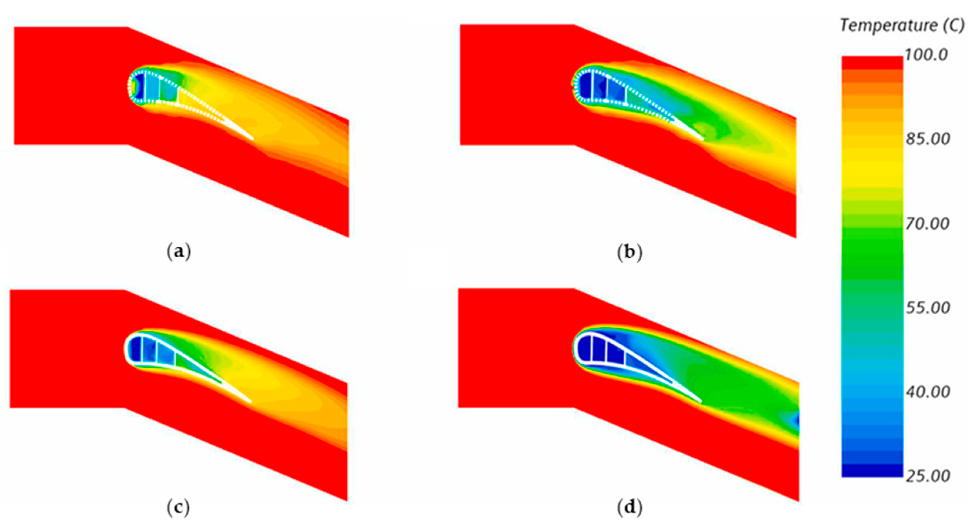
| [73] | A C3X single-turbine blade with different cooling methods | IR thermography (ηo) | ) = 100–400 LPM | The maximum area-averaged ηo of the transpiration-cooled single turbine blade was 0.58. |
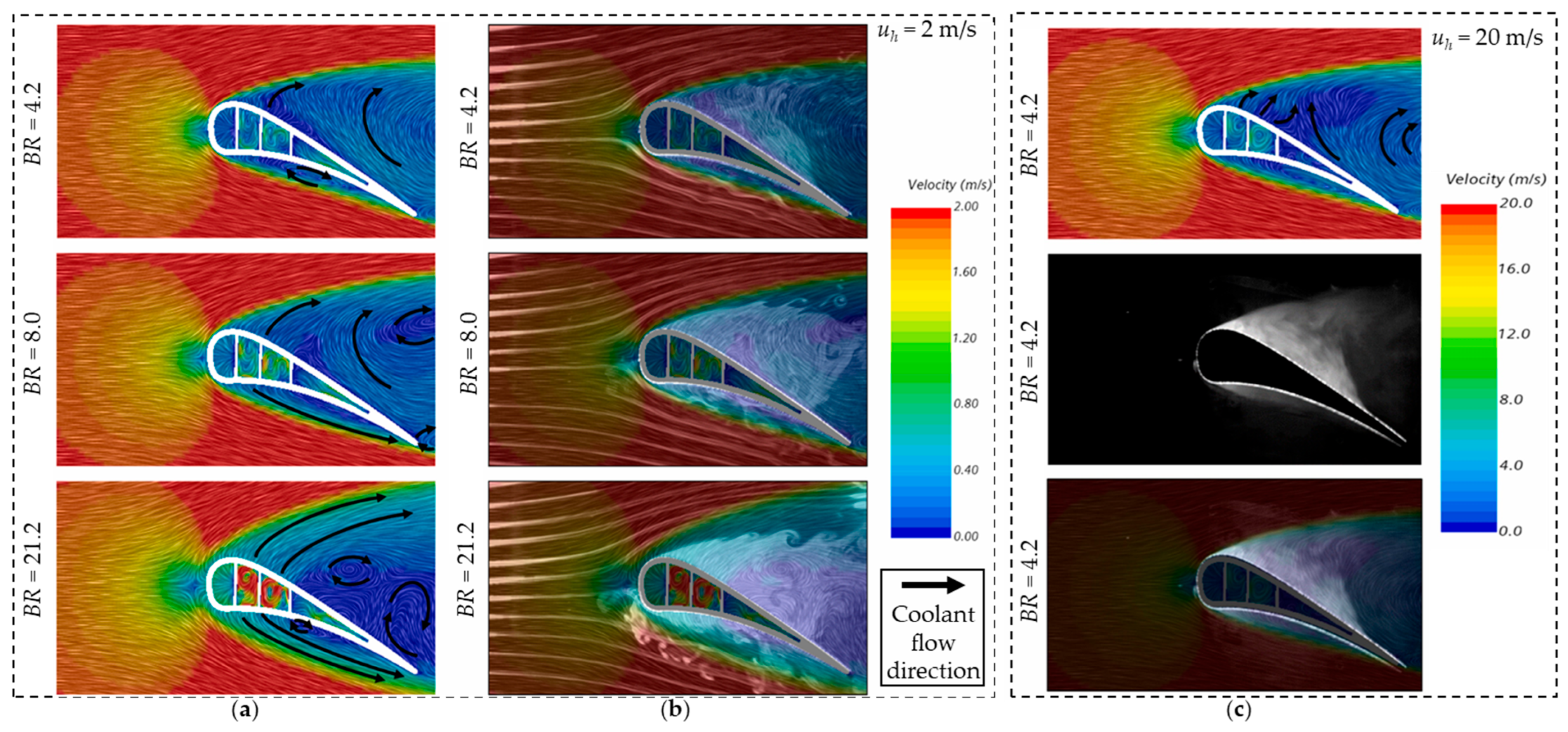
| [95] | Smoke-laser with a high-speed camera (u) | = 0–200 LPM; BR = 4.2–21.2 | The coolant film on the transpiration-cooled blade was more stable. | |
| [30] | A C3X cascade-turbine blade with different cooling strategies | IR thermography (ηo) Smoke-laser with a high-speed camera (u) | = 50–300 LPM | The maximum area-averaged ηo of the transpiration-cooled cascade turbine blade was 0.7. |
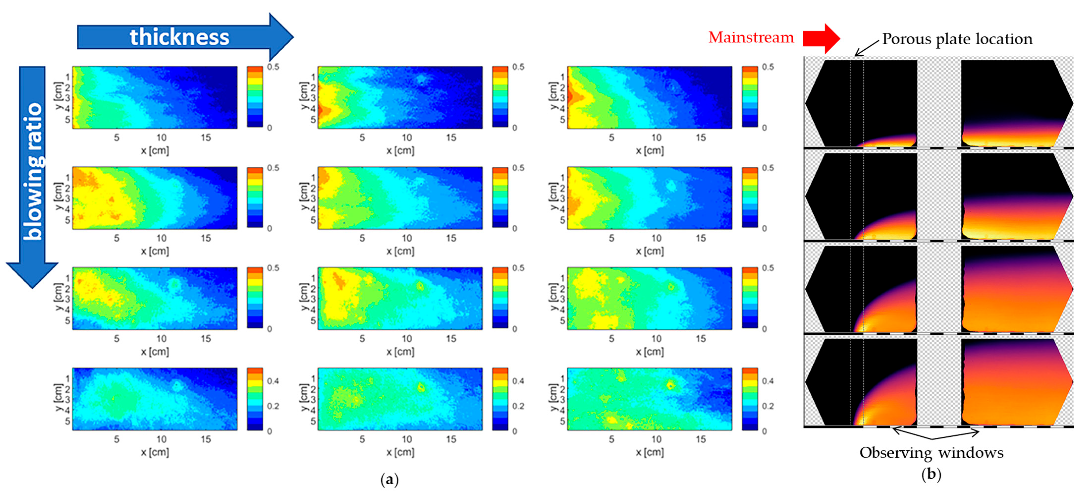
| [74] | Porous-media transpiration-cooled plates | TLC (h, ηo) IR flow visualization (u) | Th = 70 °C; Tc = Ambient temperature (TAmb); Reh = 25,000 (uh = 3.4 m/s); BR ≈ 0.4–2.0 | The highest area-averaged ηa of the transpiration-cooled plates was less than 0.4. |
| [75] | Porous-media transpiration-cooled specimens | Static pressure taps (CD) | The ratio of plenum stagnation and atmospheric pressures (PR) = 1.02–1.7. | The CD of the 90° laser direction was 0.02–0.07, lower than that of the 67° model. |
| [64] | Uniform and graded IWP TPMS plates | IR thermography (T) | Th = 420–480 K; Mach number of mainstream (Mah) = 2.8; F = 0.1–0.6%. | The graded IWP reduced the maximum local temperature by around 20% compared to a uniform one. |
| [79] | Transpiration cooling combined with lattice structures on a leading edge | Static pressure taps (CD) | PR = 1–1.3. | The highest CD was 0.17 in the impingement sleeve. |
| [96] | PSP (ηa) | Tc = Tamb; Reh = 825,313; BR = 0.03–0.15. | The area-averaged ηa was 0.11–0.34, and the maximum pressure loss was about 4.4 kPa. | |
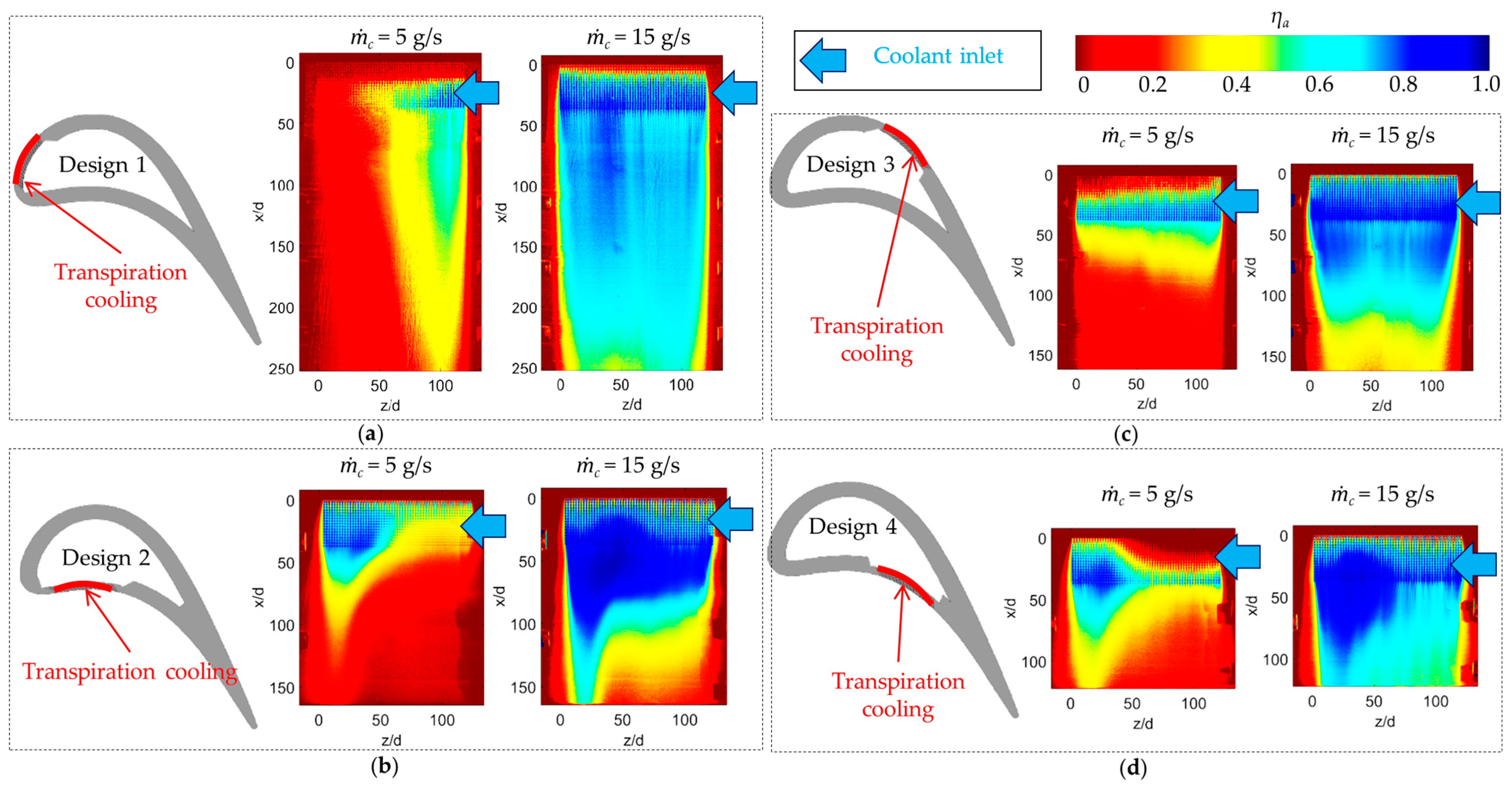
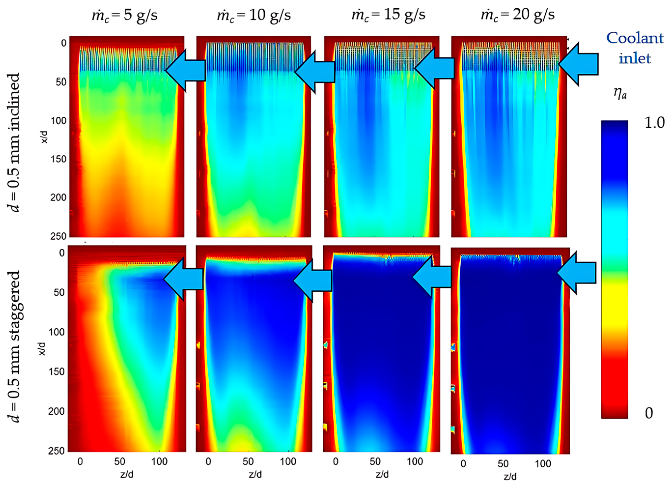
| [97] | Perforated transpiration-cooled turbine blade | PSP (ηa) | = 5–20 g/s (BR ≈ 0.1–0.5). | The staggered arrangement on the SS turbine blade showed the highest area-averaged ηa of 0.95. |
| [51] | Partitional walls in transpiration-cooled plates | IR thermography (ηo) | Th = 340 K; Tc = 296 K; uh = 11 m/s; F = 1–3% | The maximum area-averaged ηo of the sintered and AM models was 0.74 and 0.71. |
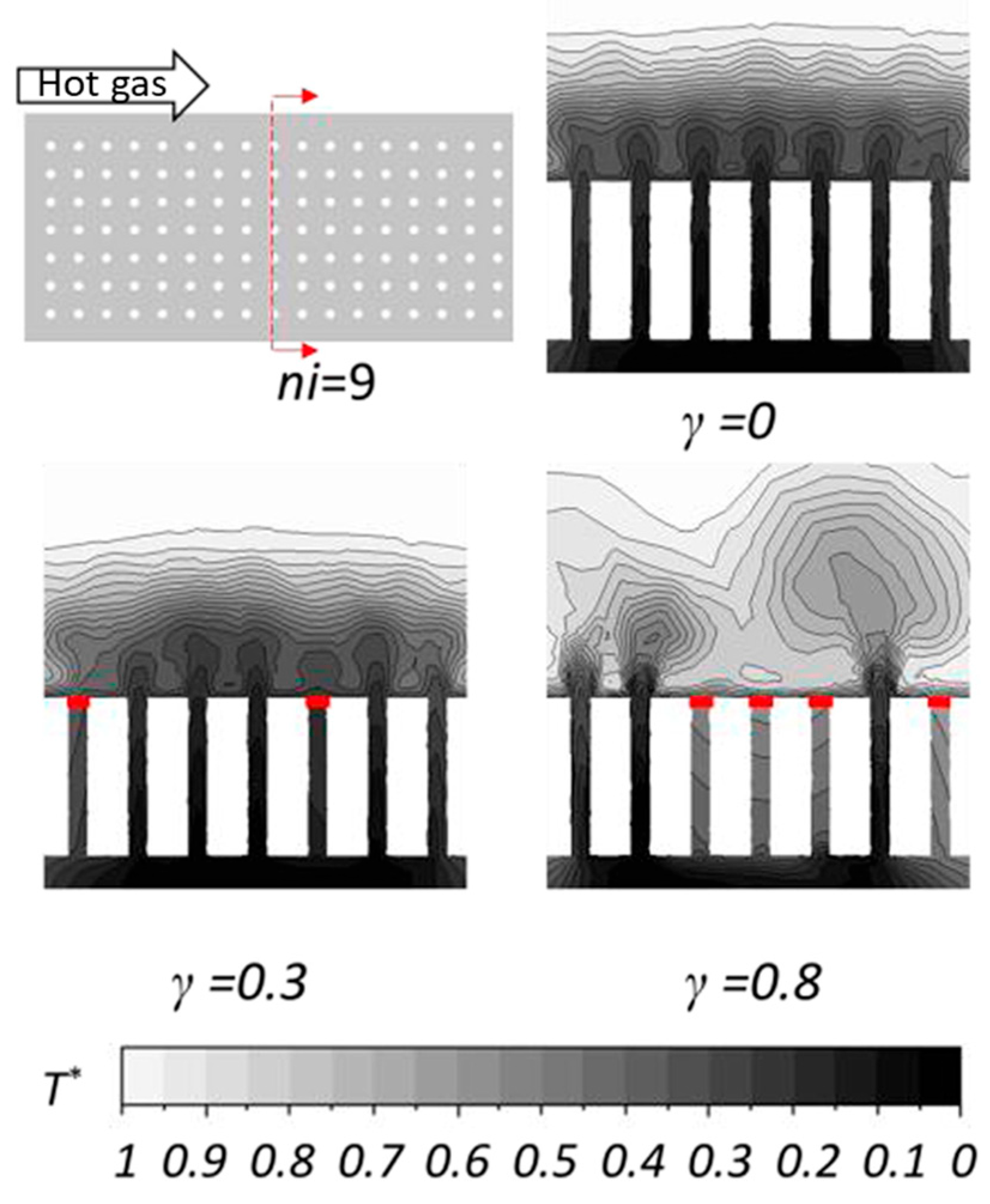
| [98] | PSP (ηa) | Reh = 395,000 (uh = 21.6 m/s); BR = 0.1–0.7. | The highest area-averaged ηa values of the 0% and 60% blockage models were about 0.68 and 0.4. | |
| [76] | Different transpiration topology designs | IR thermography (ηo) | Th = 45–60 °C; Tc = 21 °C; Reh = 98,000 (uh = 11 m/s); BR = 1–3; F = 1.2–3.6% | The blood vessel-shaped designs showed ηo of 0.35–0.57. |
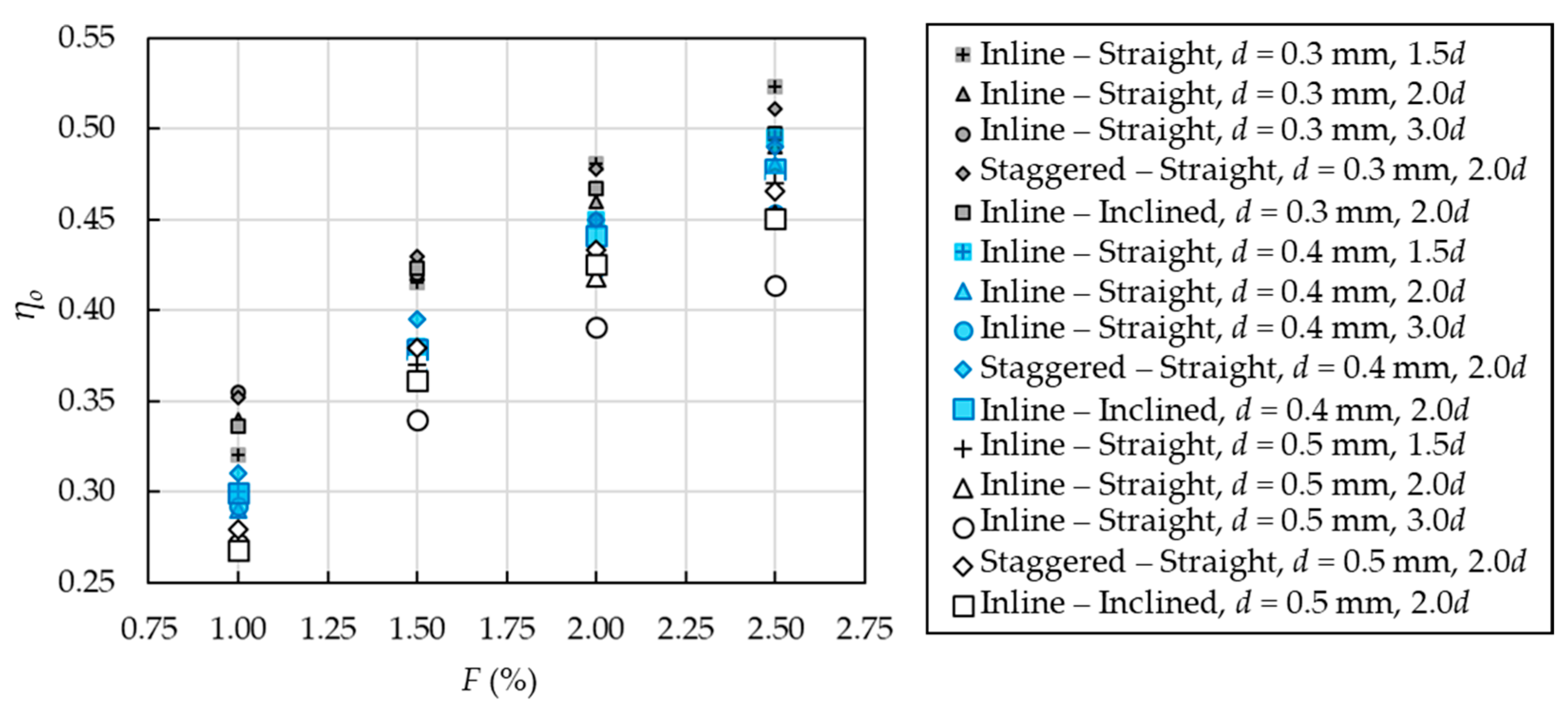
| [77] | Different perforated transpiration designs | Th = 50–60 °C; Tc = 21 °C; Reh = 98,000 (uh = 11 m/s); F = 1.0–2.5%. | The optimal design was the 3d-pitch (d = 0.3 mm) with ηo of 0.48 and a relative UTS of 0.74. | |
| [78] | Integrated lattice transpiration cooling structures | The area-averaged ηo was reduced by 12% when inserting a lattice in the transpiration-cooled plate. The highest area-averaged ηo was 0.67 in the pure transpiration cooling model. | ||
| [99] | Different perforated transpiration designs | IR thermography (ηa) | Th = 50 °C; Tc = 21 °C; BR = 0.125–0.5 | The spanwise-averaged ηo increased from 0.44 to 0.73 in the 2.5d-pitch (d = 0.5 mm) at BR = 0.5, higher than various multirow film hole studies. |
| [100] | Wire mesh porous transpiration-cooled plate | IR thermography (ηa) | Th = 295 K; Tc = 21 °C; uh = 18.8 m/s; F = 0.4–5.2%. | The area-averaged ηa values were within 0.05–0.36. |
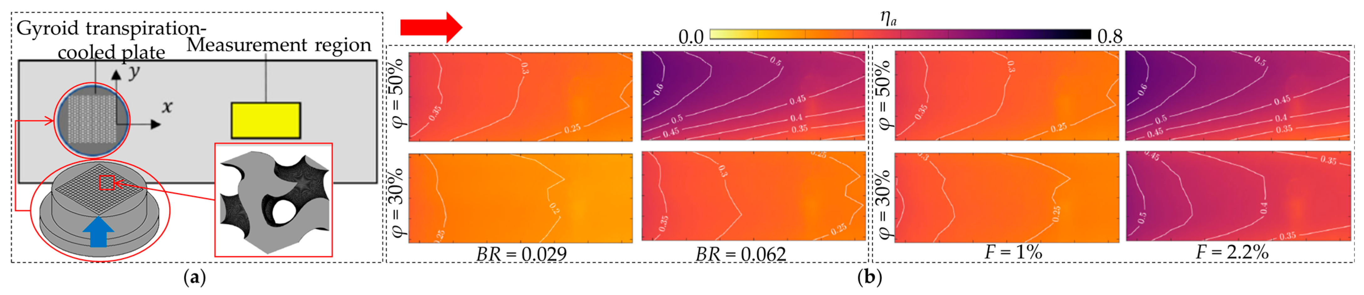
| [101] | Different porosities and injection ratios of the Gyroid TPMS model | IR thermography (ηa) | Tc = 80 °C; Mah ≈ 0.27 (uh = 87.5 m/s); ρh/ρc = 0.83; F = 1.4–3.1%. | The area-averaged ηa values were around 0.3–0.5. |
| [92] | Different porosities of Diamond TPMS plates | PSP (ηa) | Th = 50–60 °C; Reh = 256,000 (uh = 33 m/s); F = 0.68–1.60%. | The model with the φ of 30%, 40%, and 50% showed the highest area-averaged ηa by 0.49, 0.69, and 0.75. |
| [81] | Different TPMS transpiration cooling designs | The Diamond, Gyroid, and Koch models demonstrated the maximum area-averaged ηa by 0.76, 0.71, and 0.79. | ||
| [102] | Different unit cell sizes of Diamond TPMS plates | The model with the unit cell size (L) of 1.9, 2.5, and 3.1 mm provided the highest area-averaged ηa by 0.75, 0.71, and 0.66. |
| Equation | Non-Stochastic Transpiration | Random-Pore Porous-Media Model |
|---|---|---|
| Mass conservation | ||
| Momentum | ||
| Energy (Fluid) | ||
| Energy (Solid) | (no internal heat generation) | |
| Fluid–solid interface boundary conditions | ||
| Ref. | Main Study | Tool | Method | Material | Mesh Details |
|---|---|---|---|---|---|
| [95] | Flow characteristics on a transpiration-cooled single-turbine blade | STAR-CCM+ | k-ω | Porous media with stainless steel in the transpiration model |
|
| [30] | Flow and temperature distributions on a transpiration-cooled cascade-turbine blade | STAR-CCM+ | SST k-ω |
| |
| [25] | Flow and overall cooling effectiveness of a non-uniform porosity transpiration-cooled blade | ANSYS FLUENT | SST k-ω |
| |
| [96] | Adiabatic cooling effectiveness and pressure loss of transpiration-cooled leading edge | STAR-CCM+ | SST k-ω | Adiabatic |
|
| [110] | Effects of outlet angle and pattern on transpiration-cooled plates | ANSYS FLUENT | SST k-ω | Inconel 600 |
|
| [82] | Transpiration-cooled plates with TPMS structures | ANSYS FLUENT | SST k-ω | Stainless steel |
|
| [51] | Effects of partitional walls on flow and overall cooling effectiveness in transpiration-cooled plates | ANSYS FLUENT | k-ω | Inconel 718 |
|
| [111,112] | Pore blockage effects on perforated transpiration-cooled plates | ANSYS CFX | SST k-ω | ks = 1 W/(m·K) |
|
| [113] | Pore blockage effects on tree-like transpiration-cooled plates | ANSYS FLUENT | SST k-ω | Inconel 718 |
|
| [114] | Pore blockage effects on the oriented porous structure | ANSYS FLUENT | - | Porous media with CMC (ks = 2 W/(m·K)) |
|
| [89] | Effects of hole diameter, Biot number, and coolant distribution on perforated transpiration-cooled plates | ANSYS FLUENT | SST k-ω | Inconel 718 |
|
| [115] | Effects of solid thermal conductivity, wall thickness, hole spacing, and TBC on AM transpiration cooling plates with inhomogeneous porosity | ANSYS FLUENT | k-ω | Inconel 718 and ceramic (ks = 1, 11 and 50 W/(m·K)) |
|
| [116] | Transpiration-cooled plates with varied porosity configurations and pressure gradients | ANSYS FLUENT | SST k-ω | Inconel 718 (Temperature-dependent properties) |
|
| [117] | Swirl-chamber effusion with different inclination angles and compound angles | ANSYS FLUENT | RSM | ks = 0.5 W/(m·K) |
|
| Ref. | Printed Geometry | Manufacturing Method (Surface Treatment) | Material | Design Values | Deviations from Designs |
|---|---|---|---|---|---|
| [66] | Oblique cylinder hole | Etching (Polish) | Stainless steel | d = 0.063 mm pitch = 0.063 mm φ = 91% | d ≈ −1% to −4% pitch ≈ −1% φ ≈ −1% to −7% |
| Truncated-cone hole | Laser drilling (Polish) | d = 0.06–0.24 mm pitch = 0.6–2.4 mm φ = 91% | d ≈ −8% to −30% pitch ≈ −2% to −5% φ ≈ −15% to −48% | ||
| Round hole | SLM (Laser clean) | d = 0.06–0.24 mm pitch = 0.6–2.4 mm φ = 91% | d ≈ −2% to −37% pitch ≈ −33% to 0.2% φ ≈ −4% to −77% | ||
| Quadratic-truncated-cone hole | SLA | Resin | d = 0.25 mm pitch = 2.686 mm φ = 1.0% | d ≈ −0.4% to 17.2% pitch ≈ −0.6% to −0.7% φ ≈ −29% to 9% | |
| [76] | 0.3 mm-round hole (3 d-pitch) | DLMS (Heat treatment, Supporting removal, De-powdering process) | Inconel 718 | φ = 4.13% | φ ≈ −39% |
| 0.3 mm-round hole (2 d-pitch) | φ = 8.15% | φ ≈ −12% | |||
| Sphere packing | φ = 10.73% | φ ≈ −7.2% | |||
| Wire-mesh matrix | φ = 20.89% | φ ≈ −12% | |||
| Blood vessel | φ = 13.42% | φ ≈ −15% | |||
| Film cooling | φ = 2.32% | φ ≈ −31% | |||
| [77] | Round hole (1.5 d-pitch) | DLMS (Supporting removal) | Inconel 718 | Aout = 70,685.8 μm2 d = 0.3 mm | Aout ≈ −39%, d ≈ −22% |
| Round hole (2 d-pitch) | Aout ≈ −49%, d ≈ −28% | ||||
| Round hole (3 d-pitch) | Aout ≈ −44%, d ≈ −25% | ||||
| Round hole (1.5 d-pitch) | Aout = 125,663.7 μm2 d = 0.4 mm | Aout ≈ −36%, d ≈ −20% | |||
| Round hole hole (2 d-pitch) | Aout ≈ −41%, d ≈ −17% | ||||
| Round hole (3 d-pitch) | Aout ≈ −35%, d ≈ −19% | ||||
| Round hole (1.5 d-pitch) | Aout = 196,349.5 μm2 d = 0.5 mm | Aout ≈ −29%, d ≈ −16% | |||
| Round hole (2 d-pitch) | Aout ≈ −28%, d ≈ −15% | ||||
| Round hole (3 d-pitch) | Aout ≈ −27%, d ≈ −14% | ||||
| [92] | Diamond TPMS lattice | SLA | Resin | φ = 30% | φ = −39% |
| φ = 40% | φ = −24% | ||||
| φ = 50% | φ = −15% | ||||
| [80] | Gyroid TPMS lattice | LPBF | Inconel 625 | φ = 61% | φ = −1% |
Disclaimer/Publisher’s Note: The statements, opinions and data contained in all publications are solely those of the individual author(s) and contributor(s) and not of MDPI and/or the editor(s). MDPI and/or the editor(s) disclaim responsibility for any injury to people or property resulting from any ideas, methods, instructions or products referred to in the content. |
© 2025 by the authors. Licensee MDPI, Basel, Switzerland. This article is an open access article distributed under the terms and conditions of the Creative Commons Attribution (CC BY) license (https://creativecommons.org/licenses/by/4.0/).
Share and Cite
Yeranee, K.; Rao, Y. A Review of Recent Research on Flow and Heat Transfer Analysis in Additively Manufactured Transpiration Cooling for Gas Turbines. Energies 2025, 18, 3282. https://doi.org/10.3390/en18133282
Yeranee K, Rao Y. A Review of Recent Research on Flow and Heat Transfer Analysis in Additively Manufactured Transpiration Cooling for Gas Turbines. Energies. 2025; 18(13):3282. https://doi.org/10.3390/en18133282
Chicago/Turabian StyleYeranee, Kirttayoth, and Yu Rao. 2025. "A Review of Recent Research on Flow and Heat Transfer Analysis in Additively Manufactured Transpiration Cooling for Gas Turbines" Energies 18, no. 13: 3282. https://doi.org/10.3390/en18133282
APA StyleYeranee, K., & Rao, Y. (2025). A Review of Recent Research on Flow and Heat Transfer Analysis in Additively Manufactured Transpiration Cooling for Gas Turbines. Energies, 18(13), 3282. https://doi.org/10.3390/en18133282