Abstract
Multipurpose heat pumps are devices able to provide simultaneously heating and cooling requirements. These devices concurrently provide useful thermal energy at condenser and evaporator with a single electrical energy input, potentially achieving energy savings as heat-recovery and co-generative technology. Despite their potential contribution to the energy transition goals as both renewable and energy-efficient technology, their use is not yet widespread. An application example for multipurpose heat pumps is air handlers, where cooling and reheat coils are classically fed by separate thermal generators (i.e., boiler, heat pumps, and chillers). This research aims at presenting the energy potential of multipurpose heat pumps as thermal generators of air handler units, comparing their performances with a classic separate configuration. A museum in the Mediterranean climate is selected as a reference case, as indoor temperature and relative humidity must be continuously controlled by cold and hot coils. The thermal loads at building and air handler level are evaluated through TRNSYS 17 and MATLAB 2022b, through specific dynamic models developed according to manufacturer’s data. An integrated building-HVAC simulation, on the cooling season with a one-hour timestep, demonstrates the advantages of the proposed technology. Indeed, the heating load is almost entirely provided by recovering energy at the condenser, and a 22% energy saving is obtained compared to classic separate generators. Furthermore, a sensitivity analysis confirms that the multipurpose heat pump outperforms separate generation systems across different climates and related loads, with consistently better energy performance due to its adaptability to varying heating and cooling demands.
1. Introduction
1.1. Context
A significant change in direction in world’s energy consumption is needed to reduce greenhouse gas emissions [1,2]. Within this aim, a challenging set of objectives on carbon emissions reduction has been stated by international entities for the next decades: examples are the “Green Deal” in the European Union [2], the “Inflation Reduction Act” in the United States [3], and the “Paris Agreement” for all the United Nations [4]. Also, China [5], Australia [6], the United Kingdom [7], and New Zealand [8] have developed specific plans to limit emissions.
Currently, about 40% of the global energy consumption is taken up by the building sector, specifically for heating and cooling purposes [2]. In this context, heat pumps (HPs) are increasingly considered as alternative heating generators, replacing old and inefficient boilers and furnaces and reducing the need for fossil fuels. Their environmental convenience increases when combined with renewable electrical energy systems. According to IEA [9], “heat pumps are much more energy-efficient than other renewable and conventional building technologies”. Moreover, the possibility of delivering cooling service as well, through a reversing valve, represents another advantage of HPs, which can be then used for both services. In addition, national governments have recognized HPs as strategic technologies for the integration of renewable energy sources (RESs) in buildings. In the most classic configuration, HPs use electrical energy from photovoltaic modules to provide heating and cooling services, but they can also be successfully implemented in more complex systems and microgrids (e.g., energy communities), exploiting advance controls and demand-response strategies to increase the use of RESs in building. Special subsidies and financial support are thus often provided by governments to encourage HP installation: examples include several countries in Europe [10] and the US [11]. As a consequence, in the period of 2014–2022, the annual sales of HPs more than tripled in Europe [12] while data from the last two years report a drop in sales, probably due to a variety of reasons, such as variability of electricity prices, uncertainties on national and local policies with remodulation of the aforementioned subsides, a shortage of installers, long waiting periods, higher cost of installation, a slowdown in the construction sector, and others [13,14]. However, heat pumps remain a strategic technology, with their development clearly outlined in all EU Member States’ National Energy and Climate Plans, which include ambitious deployment targets contributing to the European goal of 60 million heat pumps by 2030 [14,15].
A special typology of HP is the so-called multipurpose heat pump (MP-HP), which simultaneously provides heating and cooling loads by recovering thermal energy at both heat exchangers. MP-HPs can be considered as “combined thermal generators”, as they can work in different operative conditions, providing either heating and cooling energy, or both of them. In this latter case, MP-HPs can change the refrigerant operating points during the inverse cycle to “follow” the energy loads. Their use is particularly recommended in applications where both heating and cooling are needed, as the combined production of useful energy helps prevent waste heat from being released into the environment, generally improving energy efficiency and increasing the share of renewable energy in the heating and cooling sector.
1.2. Literature Review
Heat pumps are a proven commercially available technology used for space heating, cooling, and hot water in buildings. This technology is considered to use renewable energy from the surroundings (i.e., the external source) and electrical energy to provide the required loads. Their integration in building stock is considered central in national and international plan (e.g., [16]) to reduce carbon emissions.
HPs typically use air, water, or ground as principal heat sources and sinks. The choice of the heat source/sink depends on the geographic location, climatic conditions, and capital expenditure [17]. Generally speaking, outdoor air-sources are widely used in most applications thanks to their universal availability and low-to-moderate purchase and operation expenditure. Efficiency and capacity are, however, hugely variable with outdoor temperature. Water and ground-source HPs have instead moderate-to-high costs, and the availability of these sources depend on proximity (water) or soil condition (ground); however, performance of these HPs is higher compared to that of the air-source.
MP-HPs are a special typology of HPs as they are able to recover heat at the condenser while using the evaporator for cooling purposes, reducing the waste heat disposal at outdoor units. Despite being known in the literature and also commercially available, scientific research has not intensively focused on applications and benefits of the use of MP-HPs in the building sector. For example, a SCOPUS database search using the keywords “multipurpose heat pump” shows only three research articles [18,19,20]. Other articles were revealed by a query using other keywords (such as “multi-heat pump”, “multi-functional heat pump”, “polyvalent heat pump”, “bi-functional heat pump”, or “total recovery chiller”). For this technology, in fact, several different names are used as synonyms, even if they are not entirely correct: for example, a total recovery chiller identifies a chiller actively controlling only the thermal energy at the evaporator, recovering thermal energy at condenser, whereas a multipurpose heat pump indicates a device that can actively change operative conditions at each heat exchanger. As an additional example, “bi-functional heat pumps” as defined in [21] are “machines that provide both heating and cooling, either simultaneously or in different seasons via cycle reversing”: this definition thus does not correspond to the one here used (i.e., machines that provide both heating and cooling simultaneously).
In general, the literature appears fragmented, with most of the articles focusing on experimental tests of this device, primarily aimed at enhancing energy efficiency. For example, in the work by Agrawal et al. [22], a trans-critical CO2 MP-HP was tested during a test field where heating and cooling services were simultaneously required. The authors measured the impact of inlet temperature, water flow rate, and refrigerant charge on COP to determine the optimal operating conditions for best performance. Compressor speed and level of desuperheating were found to be optimization parameters for MP-HP performance in [23]. In [24], the authors tested a prototype MP-HP, which can realize five different operative conditions, with four types of heat source combinations at the evaporator (air only, water only, air and water in parallel, air and water in series). Standardized tests were carried out in environmental chambers. Results showed that the parallel use of both sources result in the highest and most constant performances (around 4.50, while the air only and water only have, respectively, around 4.3 and 4.2). The authors of [25] developed a prototype of a MP-HP with an innovative component to enhance energy efficiency, the suction line heat exchanger. This heat exchanger allows for an increase in performance up to 30% in some working conditions; however, the performance values were found strongly influenced by heat sources/sink temperatures. The authors concluded that more research is needed for MP-HPs, considering the interest of meet the cooling, heating and domestic hot water (DHW) needs simultaneously without local carbon emissions. In [26], a dynamic simulation of a MP-HP with an innovative control system (namely the load–reset–control method) was carried out. The control system was able to reduce the negative effects of MP-HP when providing unbalanced loads: in particular, either the cooling or heating temperature is adjusted to improve load balances and heat pump performances while maintaining acceptable comfort levels inside the building. The works by Byrne and colleagues [27,28,29] delt with the design, building, and enhancement of a MP-HP, defined by the authors as “HPS” (“heat pumps for simultaneous heating and cooling”). First, the components of the MP-HP were designed and the performances using two different refrigerants (i.e., R407C and CO2) were compared [27]. Carbon dioxide was found to allow higher performances (-27.4% of electricity required) and a high amount of recovered energy at the condenser through subcooling (about 30% of the total heat exchanged). Subsequently, a prototype was realized [28] and tested under some test field conditions. The experimental data agreed with data obtained by means of a thermo-physical model of the MP-HP. In successive research [29], the authors compared the performance results of two prototypes (using, respectively, R407C and R290 as refrigerant): the propane-based MP-HP was found to reach higher performance (+16.6% compared to a standard reversible heat pump), also because of a different design of the components. In another piece of research [30], different low-GHP (global warming potential) refrigerants were compared through simulation, estimating their energy performance and environmental sustainability. Among the several alternatives, R744 was found to be the suggested solution, being both energy-efficient and clean.
The previously analyzed literature reveals that research on MP-HPs has been developed on experimental tests, primarily in standard conditions, seeking the factors mostly influencing performances and testing different components’ design, working conditions, and refrigerants to increase efficiency. A limited number of papers focuses instead on case studies to assess the effective operation conditions of this device. As an example, in [31], the authors compared the efficiency of a CO2 trans-critical MP-HP in providing different services: heating, domestic hot water, and cooling in the first case and cooling and desalinization in the second one, investigating potentials and drawbacks of each possible configuration using different performance indexes (e.g., COP and exergy efficiency, water production). In [32], the energy required to a MP-HP to provide heating, cooling, and domestic hot water (DHW) was evaluated for 10 reference US cities. Those energy requirements were compared to the ones needed to a “classic” solution using a heat pump and an electric water heater, and savings up to 50% were found. Ghoubali et al. [33] simulated and compared the performance of a MP-HP in three different French climates and three different types of buildings (a low-energy building, an office, and a retail store). The results show that low-energy buildings are the most suitable typology of building where installing a MP-HP due to the simultaneous need for cooling and DHW for a long period of the year; the other two buildings do not represent market target for MP-HP, having limited DHW requirements. Limited variations in seasonal performances are also found varying the external climate and the employed refrigerant.
1.3. Research Aim
As pointed out by the previous literature analysis, a limited number of scientific works has compared MP-HPs and more “classic” solutions in providing specific building energy needs, then estimating the actual suitability of this generator in different indoor environments. Moreover, according to the best of the authors’ knowledge, no scientific research has been focused on MP-HP providing heating and cooling for air handlers. The use of those devices is recommended in hot and humid climates, especially in large non-residential buildings where the air should be clean, cooled, and dehumidified. In air handlers, cooling and heating are simultaneously required at two of the air handler components, i.e., cooling coils and reheat coils: thus, they represent a suggested application of MP-HPs. In current state of the art, separate generators are typically used to provide thermal energy at the two heat exchangers.
In light of this, the present research aims at estimating the potential energy benefits of MP-HPs as thermal generator in an environment where indoor temperature and relative humidity are kept constant by means of an air handling unit (AHU). A comparison with a “classic” solution, where AHU is fed by an electric heat pump and a chiller, is provided to check the effective suitability. The core concept of the present research activity is schematically represented in Figure 1.
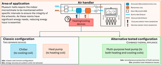
Figure 1.
Core concept of the present piece of research.
The remainder of the paper is organized as follows. In Section 2, the model of the MP-HP is discussed, alongside with the models used in the “classic” configuration, with the two separate generators. Section 3 presents the case study used for the comparison: a museum hall, where the strict range of indoor microclimate parameters is maintained by an AHU, to avoid degradation. Section 4 discusses the results and finally Section 5 summarizes the conclusions.
2. The Model
In this section, the dynamic model of the simulated integrated system, consisting of a HP and an AHU, is presented. In particular:
- Section 2.1 presents the dynamic model of a MP-HP system, where the evaporator and the condenser can be simultaneously used for the energy needs of an AHU maintaining a museum room in fixed thermal indoor conditions. Figure 2 shows that when both cooling and heating coil at AHU are operating, both water evaporator and condenser of the MP-HP are used. If one of the two AHU heat exchangers is not necessary, the corresponding MP-HP air OU is used. A control system (CS in the figure) manages the three-way diverter valves, letting the refrigerant moving towards the air- or the water-heat exchanger.
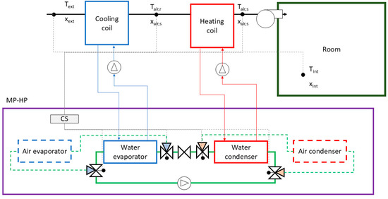 Figure 2. Configuration with MP-HP and AHU. The blue and red solid lines represent the water pipes from MP-HP heat exchangers to AHU cooling and heating coils, respectively. The grey lines represent the control-actuator system. As for the MP-HP, the green solid lines represent the circuit when the two water heat exchangers are used. The green dashed lines represent the circuit when the air source is used.
 - Section 2.2 presents a classic configuration where energy at the AHU is provided separately by two air-source generators: a heat pump (for the heating coil) and a chiller (for the cooling coil); see Figure 3.
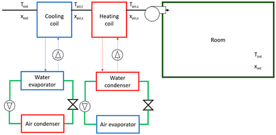 Figure 3. Configuration with heat pump, chiller, and AHU (classic configuration). The blue and red solid lines represent the water pipes from MP-HP heat exchangers to AHU cooling and heating coils, respectively. The green solid lines represent the circuit of the refrigerant inside the two devices.
2.1. Configuration Using a Multipurpose Heat Pump (MP-HP)
In this configuration, the AHU loads are met by an existing MP-HP, for which nameplate datasheets are available [34]. Additional data regarding variation of capacity and performance with capacity ratio and source temperature are provided by the manufacturers. The chosen MP-HP is charged with R410A and designed with plate heat exchangers for the IUs and finner pack copper/aluminium for the OUs. The appliance has an operating field of temperature ranging from −15 °C and 46 °C for external air up to 55 °C for working fluid production.
To meet the dynamic load of the museum room, which should be maintained at indoor conditions (, ) for artwork preservation, the AHU can require (i) heating only (); (ii) cooling only (); (iii) both heating and cooling ( and ). The time-dependent load profile at AHU depends on external conditions (ambient temperature and humidity) and indoor gains (e.g., people in the museum).
According to the manufacturer’s datasheet [34], the MP-HP can be operated in three different modes:
- Mode 1—Classic chiller: the MP-HP operates as an air-to-water chiller, rejecting thermal energy at the air-source condenser. The compressor absorbs a certain amount of electrical energy, which is function of the supply temperature at AHU () and capacity ratio () as in
- Mode 2—Classic heat pump: the MP-HP operates as an air-to-water heat pump, exchanging thermal energy at the air-source evaporator. The electrical energy absorbed by the compressor is function of the supply temperature at AHU () and capacity ratio () as in
- Mode 3—Multipurpose heat pump: in this configuration, the AHU requires both heating and cooling loads, and both the MP-HP water-source heat exchangers are used. As the loads at heat exchanger can be unbalanced, surplus energy at condenser/evaporator is considered stored in water buffers and later used. The following strategy, based on real implemented control system [23], is used:
- (a)
- The MP-HP tries following the cooling load, providing . This quantity matches the energy actually required at the AHU (). Then, the absorbed electrical energy at the compressor and the thermal energy at the condenser ( and , respectively) are evaluated. Supply temperatures to the reheat and cooling coils ( and , respectively) and partial load conditions () are
- (b)
- The thermal energy at the condenser, , is compared to the energy required at AHU reheat coils,
- (c)
- If , the MP-HP operates in “following cooling load” conditions. The surplus energy at the condenser is stored in a hot buffer. The following equations apply:
- (d)
- If , the MP-HP cannot follow cooling load, as there is not an additional heat generator that could provide the deficit energy at AHU reheat coil. Consequently, the MP-HP operates in “following heating load”, providing an amount of energy at the condenser equal to the one needed at AHU. The surplus energy at evaporator is stored in the cold thermal buffer and later used. The following equations apply:
For the assessment of the coefficient of performance of MP-HP in the various operational modes, we implemented polynomial fitting regression on the nameplate data. The following equations apply:
- For Mode 1 (Classic chiller):
- For Mode 2 (Classic heat pump):
- For Mode 3 (Multipurpose heat pump):
Table 1, Table 2, and Table 3 report the data of efficiency and delivered thermal output for the MP-HP working in Mode 1, Mode 2, and Mode 3, respectively [34].

Table 1.
Values of cooling capacity, input electrical energy, and performance (COP) of a multipurpose heat pump operating in Mode 1— “Classic chiller” (data provided by manufacturer [34]). CR means capacity ratio.
Table 2.
Values of heating capacity, input electrical energy, and performance (COP) of a multipurpose heat pump operating in Mode 2—“Classic heat pump” (data provided by manufacturer [34]). CR means capacity ratio.
Table 3.
Values of cooling capacity, input electrical energy, and performance (COP) of a multipurpose heat pump operating in Mode 3—“MP-HP” (data provided by manufacturer [34]). CR means capacity ratio. Heating capacity can be derived by summing the cooling capacity and the electrical energy.
Figure 4 reports a scheme of the control strategy adopted by the MP-HP. For simplification purposes, both the cold and hot water buffers are considered ideal devices, neglecting the effects of thermal losses and constraints in the energy transfer.
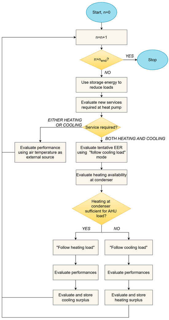
Figure 4.
The control strategy of the MP-HP.
2.2. Classic Configuration (Separate Heat Pump and Chiller)
The classic configuration, illustrated in Figure 3, includes a chiller and a heat pump, separately connected to the cooling coils and reheat coils of the AHU, respectively. The two generators’ thermal output and performances are simulated using the same regression equations discussed in Equations (6) and (7). The nameplate coefficients are those in Table 1 and Table 2, in other words, the same used for the MP-HP in the “Classic chiller” and “Classic heat pump” configurations. The performance coefficients are named and .
3. Application to a Case Study for Comparison
3.1. The Case Study
The two systems’ configurations are compared by means of an integrated dynamic simulation of a museum hall located in the center of an historic town in central Italy. The room has a floor area of 100 m2 and a volume of 500 m3, with masonry external walls (average total thickness: 0.7 m, average thermal transmittance: 0.9 Wm−2K−1). There is no glazed area.
The hall is used for temporary modern and contemporary artworks exhibitions. Depending on the exposed artworks, the indoor conditions to be maintained change. In the present study, we choose the following indoor conditions to be maintained:
- Indoor temperature: 25 °C, control dead band ±1 K;
- Indoor relative humidity: 50%, control dead band ±2%.
An AHU provides a fresh air flow rate (typically with a flow rate of about 5–6 vol/h) at specific values of temperature and humidity ratio, to maintain the desired thermal conditions inside the room. The AHU consists of a cooling coil (nominal capacity: 40.2 kW), a steam vaporizer, a reheat coil (nominal capacity: 13 kW), and a fan.
An hourly simulation of the integrated building–AHU–generation system is performed under the following conditions:
- Outdoor climate values (i.e., ambient temperature, relative humidity, horizontal solar radiation) from a typical meteorological year [35];
- Time-dependent number of visitors inside the museum hall, varying with the day of the week from 9 a.m. to 7 p.m., influencing sensible and latent internal gains [36];
- AHU activated 24/7 to ensure the maintenance of thermal conditions inside the hall.
Further details about the areas, orientation, and thermal properties of the museum opaque walls and windows can be found in [37,38].
To dynamically simulate the building–AHU–generator system, the following models are concurrently used:
- TRNSYS [39] is used to estimate the sensible and latent loads required for the museum hall;
- An AHU dynamic model [40] in MATLAB [41] is employed to assess the values of temperature and humidity ratio of the supply air at the beginning and end of each component (e.g., cooling and reheat coils, vaporizer). Mass and heat balance and ϵ-NTU equations are implemented for the simulation of each AHU section. In particular, referring to Figure 2, the values of temperature and humidity ratio exiting the cooling coils ( and ) and reheat coils ( and ) are necessary for the following simulation of the supply temperatures at the generators ( and );
- A dynamic model of the heat generators in the two configurations (MP-HP and classic configuration) is implemented in MATLAB [41], assessing the electrical energy load to guarantee the indoor conditions.
We stress that, to obtain the desired values of temperature and humidity ratio at each AHU component’ end, the water supply temperatures, and , are the same, independently from the generator; in fact, those values depend on the heat transfer efficiency of the coils, and not on the heat pump characteristics. Thus, in both the classic and the MP-HP configuration, the two temporal profiles of and correspond.
3.2. Parameters of the Dynamic Simulation and Key Performance Indicators Used for Comparison
The dynamic simulation is carried out for a two-month period (from 1st July to 31st August, 1488 hours in total). The comparison between the two configurations involves the assessment of the total electrical input (), the average coefficient of performance in the various operational modes (), and the Total Efficiency Ratio (), defined as the ratio between the sum of the provided energy (both the provided heating and cooling energy), and the total electricity input:
3.3. Sensitivity Analysis to Climate
To verify that the results obtained are not solely due to the specific climate conditions of the city of Pisa, Italy, an additional sensitivity analysis was performed. In this analysis, the characteristics of the reference building, the occupancy profiles of visitors, and the configuration of the AHU were kept constant, while the reference climate was changed, thus affecting also the sensible and latent load of the rooms and in turn the heating and cooling load at the AHU coils.
The selection of the two alternative climates was based on their significant differences from Pisa (Köppen climate classification: Csa) in terms of average summer temperatures in order to meaningfully affect the building loads and consequently the loads on the two heat exchange coils of the AHU. The selected climates were Vancouver, CA, representing a cold and humid climate (Köppen climate classification: Cfb), and Bangkok, TH, representing a hot and humid climate (Köppen climate classification: Af). Hourly climate data were obtained from the PVGIS database [42]: average values, for the July and August months, are shown in Table 4.
Table 4.
Ambient temperature and relative humidity, in TMY conditions, of the three climates. The values are averaged for the months of July and August.
4. Results
4.1. Results for the Main Case Study (Pisa)
Table 5 summarizes the results of the two dynamic simulations using the indicators defined in Equations 9. The electric energy required at the AHU is lower in the MP-HP configuration (), demonstrating the soundness of the design using a “cogeneration” solution in cases where AHU requires simultaneously both cooling and heating loads. This positive result for the MP-HP configuration is confirmed by the value of , equal to 6.32, higher than the corresponding value in the classic configuration, equal to 4.98.
Table 5.
Comparison of indicators in MP-HP vs. classic configuration.
It is interesting to note that the classic configuration shows higher average performance, and , than the MP-HP one: to provide the cooling load, the average in the classic configuration is almost 4.57, whereas it is 4.50 in the MP-HP configuration (representing the MP-HP operating in Mode 1, “Classic chiller” mode). Similar results occur also for the MP-HP working in Mode 2 (“Classic heat pump” mode): the is 5.05, lower than the corresponding value in the classic configuration (). This difference is explained by considering the temperature at condenser/evaporator in the two cases, which is represented in Figure 5. The red “x” markers and the green “o” markers represent, respectively, the working conditions of the MP-HP in “Mode 1” and of the chiller, and the working conditions of the MP-HP in “Mode 2” and of the separate heat pump. The blue diamond markers, present only in the MP-HP configuration, represent the working conditions in “Mode 3”. The two figures compared show that, in MP-HP configuration, the temperature difference at the two heat exchangers is on average higher than in the classic configuration. In the latter case,
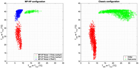
Figure 5.
Operative conditions at evaporator and condenser, in MP-HP (left) and classic configuration (right). The red markers indicate the operating conditions as a traditional air-source chiller, the green markers as an air-source heat pump, while the blue markers denote multipurpose operation.
- for the chiller, mean temperature at the water evaporator/air condenser: 8 °C/23 °C;
- for the heat pump, mean temperature at the air evaporator/water condenser: 23 °C/39 °C.
In the MP-HP configuration, instead, the temperature difference at the heat exchangers is on average higher in all the working conditions:
- in “Mode 1”, mean temperature at the water evaporator/air condenser is 7 °C/25 °C;
- in “Mode 2”, mean temperature at the air evaporator/water condenser is 15 °C/40 °C;
- in “Mode 3”, mean temperature at the water evaporator/water condenser is 8 °C/40 °C.
As the temperature lift always rises for MP-HP, the performance indexes and falls due to their definition related to a single useful effect. However, considering both useful effects produced with the same electrical input, , the MP-HP configuration is advantageous as it requires 22% less electrical energy to produce the same two useful outputs.
The results also point out that the simultaneous operation of the MP-HP for providing both heating and cooling at the AHU occurs frequently. Around 95% of the energy requirement at the reheat coil is provided by the MP-HP working in Mode 3, and only the remaining 5% is instead provided by the MP-HP working in Mode 2 (“Classic heat pump”). In fact, the MP-HP usually operates following the cooling load, storing the surplus heating load in the hot buffer and using it in the following hour. Furthermore, the MP-HP frequently works in Mode 1 (“Classic chiller”), providing about 50% of the total load using this operational mode. During that operation, heating at the reheat coil is provided by the thermal energy previously stored as surplus.
In Figure 6, the total electrical energy input is shown for a week of operation (from 1st August to 7th August) on a daily basis, highlighting the different requirements in the two configurations. The reduction in energy input ranges from 20 to 30%. Specifically, in the MP-HP configuration, “Mode 2” (the “Classic heat pump” operational mode) is rarely used, with most of the heating requirement delivered during “Mode 3” operation, i.e., recovering heat at condenser during cooling service.
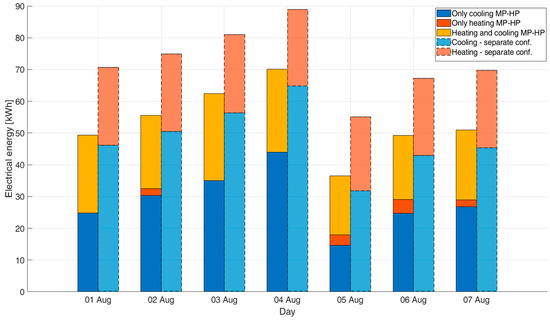
Figure 6.
Overall electrical energy inputs in the week of 1st August–7th August (daily base): comparison of the two configurations and the operational modes.
Figure 7 shows a reference day of functioning of the MP-HP, pointing out the hours where the heat generator works following either the cooling or the heating load. The AHU requirements are represented by the red (energy required at the reheat coils) and blue (energy required at the cooling coils) lines. The green and black lines represent, respectively, the energy provided at the evaporator and at the condenser of the MP-HP in “Mode 3”. In night hours, the MP-HP typically follows the heating load (the black and red lines overlap), generating a surplus of energy at the evaporator that is stored in the cold-water buffer, and used at the following hour. As an example, at “Hour 1”, the MP-HP works following the heating requirements at AHU reheat coils (), also removing a certain amount of energy at the cooling coils (). Following heating requirements, the energy removed at the water evaporator is actually higher, realizing a small cooling of the cold-water buffer (). This energy is used for the cooling of AHU cooling coils at the following hour, i.e., “Hour 2”, working then in “Mode 2” (“Classic heat pump” mode) to deliver the energy needed at the AHU reheat coils. This behavior is typical of night functioning, whereas in the daytime, the MP-HP works in “Mode 3” as well, but following instead the cooling load. This is due to the presence of visitors who increase indoor latent loads; thus, to maintain thermal conditions favorable to artwork preservation, the cooling load at AHU is increased. At “Hour 7”, the energy removed at the MP-HP evaporator is equal to the AHU requirement (), also providing at the condenser. As the AHU heating requirement is lower (), the difference of thermal energy is stored in the hot water buffer and used in the following hours.
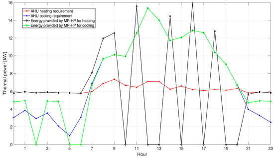
Figure 7.
AHU requirements and energy provided by the MP-HP in a reference day of functioning.
4.2. Results of the Sensitivity Analysis
Table 6 presents the results of the climate sensitivity analysis. The findings indicate that the use of a MP-HP would be beneficial even in the other climates considered, consistently showing better performance compared to the configuration with separate generation systems in all the cases. As expected, different climates affect the load demands on the AHU coils, both in terms of magnitude and in the balance between the heating and cooling coils. In all cases, however, the cooling coil is the most heavily used, primarily due to dehumidification needs. Consequently, across all three climates, the most suitable operating modes are either “Classic chiller” (Mode 1) or “Following cooling load” (Mode 3). Between these two, the distribution of usage varies depending on the climate: in Vancouver, the multipurpose mode is used more frequently, as the AHU heating coil demand is relatively high, allowing for greater energy recovery. In contrast, in Bangkok, the AHU heating demand is substantially lower than the cooling demand. As a result, the system operates more frequently in “Classic chiller” mode, since the energy discharged to the condenser during Mode 3 can later be reused via the hot coil through the TS.
Table 6.
Results for the sensitivity analysis to external climate (n.a. means “not available”).
The comparison of the performance of separate generation systems across climates is also noteworthy. These results reflect the influence of differing outdoor temperatures. In Vancouver, the relatively low ambient temperature allows for high performance levels of both the heat pump and the chiller. Accordingly, the is the highest among the three climates. Nevertheless, despite the larger temperature difference between the two heat exchangers, the MP-HP still ensures better overall system performance.
In short, drier climates benefit from higher relative electricity savings (up to −26%) due to the balanced demand between heating and cooling coils, which favors cogeneration operation (Mode 3). However, the absolute electricity savings are more significant in hot and humid climates (approximately −20 kWh/day), owing to higher latent and sensible loads in the room.
5. Conclusions
Multipurpose heat pumps are a specific type of chiller able to cogenerate both heating and cooling service thanks to the total recovery occurring at the condenser. Their installation is recommended in all those facilities and energy systems where heating and cooling requirements are simultaneously present. Air handling units represent a favorable application, as cooling coils and reheat coils are both active to provide fresh supply air at specific temperature and humidity depending on building thermal load.
Through an hourly dynamic simulation of an integrated building-HVAC system (a museum in Pisa, Italy), this paper compared the energy requirements of two HVAC configurations: a “classic” one, where an air-source chiller and a heat pump are separately used to provide energy to the AHU, and a “combined” one employing a multipurpose heat pump, to feed the two heat exchangers at the AHU simultaneously. The results showed that the “combined” configuration leads to a 22% reduction in electrical energy input compared to the “classic” one. The advantages are achieved despite the higher temperature lift (32 K vs. 18–25 K) required by the multipurpose heat pump to produce both heat and cold useful power at the same time; in fact, the total efficiency ratio increases from around 5.00 in the “classic” separate configuration to around 6.40. The climate sensitivity analysis highlights the robustness of the MP-HP approach, which proves to be advantageous even under diverse climatic conditions and related hot/cold load ratio. Although the operating mode distribution changes with climate, the MP-HP consistently achieves higher overall performance compared to systems with separate generators.
This research also hinted the importance of the presence of energy buffers to increase the amount of recovered energy, as the amount of heating and cooling requirements are typically not properly synchronized. Thus, the present research will be further developed to include a more accurate model of the buffers (e.g., sizing and operation) to achieve an optimal exploitation of the recovery potentiality of these systems depending on hot/cold load ratio. Additionally, the effective savings obtainable by means of this device in a various set of buildings and services will also be assessed.
Author Contributions
Conceptualization, P.C. and E.S.; methodology, P.C. and E.S.; software, P.C. and E.S.; validation, P.C. and E.S.; formal analysis, P.C. and E.S.; investigation, P.C. and E.S.; resources, P.C. and E.S.; data curation, P.C. and E.S.; writing—original draft preparation, P.C. and E.S.; writing—review and editing, P.C. and E.S.; visualization, P.C. and E.S.; supervision, P.C. and E.S.; project administration, P.C. and E.S. All authors have read and agreed to the published version of the manuscript.
Funding
The financial contribution received from the Italian Operative National Plan (Piano Operativo Nazionale, PON) in the framework of the Italian national project Ricerca e Innovazione 2014–2020 (PON R&I) (Azione IV.6 “Contratti di ricerca su tematiche Green”) is acknowledged.
Data Availability Statement
Data are available upon request.
Acknowledgments
We express our gratitude to AERMEC S.p.A. and in particular to Davide Cucurnia, for the sharing of datasheets and performance tables of their multipurpose heat pump. We gratefully acknowledge Daniele Testi for his suggestions and insightful comments, which greatly contributed to the development of the present research.
Conflicts of Interest
The authors declare no conflicts of interest.
Abbreviations
The following abbreviations are used in this manuscript:
| Acronyms | |
| AHU | Air handling unit |
| DHW | Domestic hot water |
| HP | Heat pump |
| MP-HP | Multipurpose heat pump |
| nZEB | Nearly zero energy building |
| Nomenclature | |
| Coefficient of performance of the heat pump | |
| Capacity ratio | |
| Electrical energy needs at compressor | |
| Thermal output | |
| Average coefficient of performance | |
| Temperature of the air after the cooling and dehumidification process in the AHU | |
| Temperature of the supply air entering the room | |
| Supply temperature at cooling coil | |
| External temperature | |
| Supply temperature at heating coil | |
| Temperature of the thermal zone (Museum’s rooms) | |
| Total efficiency ratio | |
| Supply temperature ratio | |
| Humidity ratio of the air after the cooling and dehumidification process in the AHU | |
| Humidity ratio of the supply air entering the room | |
| Humidity ratio of the external air | |
| Humidity ratio of the internal air | |
| Coefficients of the polynomial fitting of nameplate data of performances of MP-HP | |
| Subscripts | |
| C | “Only cooling” mode |
| H | “Only heating” mode |
| H&C | “Both heating and cooling” mode |
| MP-HP | Multipurpose heat pump |
| SC | Separate configuration |
| 1 | First try for the MP-HP to follow one of the required load |
References
- United Nations. Sustainable Development Goals. Goal 13: Take Urgent Action to Combat Climate Change and Its Impacts, 2015. Available online: https://www.un.org/sustainabledevelopment/climate-change/ (accessed on 12 April 2025).
- EU Parliament. The European Green Deal, 2019. Available online: https://eur-lex.europa.eu/resource.html?uri=cellar:b828d165-1c22-11ea-8c1f-01aa75ed71a1.0002.02/DOC_1&format=PDF (accessed on 12 April 2025).
- U.S. Government. Inflation Reduction Act of 2022; 2022. Available online: https://www.congress.gov/117/plaws/publ169/PLAW-117publ169.pdf (accessed on 12 April 2025).
- United Nations—Framework Convention on Climate Change, Paris Agreement, 2021. Available online: https://unfccc.int/sites/default/files/resource/parisagreement_publication.pdf (accessed on 12 April 2025).
- Ministry of Ecology and Environment of the People’s Republic of China, China’s Policies and Actions for Addressing Climate Change, 2022. Available online: https://english.mee.gov.cn/Resources/Reports/reports/202211/P020221110605466439270.pdf (accessed on 12 April 2025).
- Australian Government, Australia’s Long-Term Emissions reduction Plan, 2021. Available online: https://www.dcceew.gov.au/sites/default/files/documents/australias-long-term-emissions-reduction-plan.pdf (accessed on 12 April 2025).
- United Kingdom Government—Department for Energy Security and Net Zero, Powering Up Britain: Net Zero Growth Plan, 2023. Available online: https://www.gov.uk/government/publications/powering-up-britain/powering-up-britain-net-zero-growth-plan (accessed on 12 April 2025).
- New Zealand Ministry for the Environment, Climate Change Response (Zero Carbon) Amendment Act 2019, 2019. Available online: https://legislation.govt.nz/act/public/2019/0061/latest/LMS183736.html (accessed on 12 April 2025).
- International Energy Agency (IEA). Installation of About 600 Million Heat Pumps Covering 20% of Building Heating Needs Required by 2030; International Energy Agency (IEA): 2022. Available online: https://www.iea.org/reports/installation-of-about-600-million-heat-pumps-covering-20-of-buildings-heating-needs-required-by-2030 (accessed on 14 June 2025).
- European Heat Pump Association. Subsidies for Residential Heat Pumps in Europe; European Heat Pump Association: 2023. Available online: https://www.ehpa.org/wp-content/uploads/2023/03/EHPA_Subsidies-for-residential-heat-pumps-in-Europe_FINAL_March-2023.pdf (accessed on 14 June 2025).
- US Department of Energy. Making Our Homes More Efficient: Clean Energy Tax Credits for Consumers; US Department of Energy: 2022. Available online: https://www.energy.gov/policy/articles/making-our-homes-more-efficient-clean-energy-tax-credits-consumers (accessed on 14 June 2025).
- Statista. Annual Sales of Heat Pumps in Europe from 1990 to 2022; Statista: 2023. Available online: https://www.statista.com/statistics/1191798/heat-pump-sales-europe/ (accessed on 14 June 2025).
- European Heat Pump Association (EHPA), Market Data. 2022. Available online: https://www.ehpa.org/market-data/ (accessed on 14 June 2025).
- European Commission, Heat Pumps. 2025. Available online: https://energy.ec.europa.eu/topics/energy-efficiency/heat-pumps_en (accessed on 17 June 2025).
- European Commission, National Energy and Climate Plans. 2025. Available online: https://commission.europa.eu/energy-climate-change-environment/implementation-eu-countries/energy-and-climate-governance-and-reporting/national-energy-and-climate-plans_en (accessed on 17 June 2025).
- European Union, REPowerEU Plan. 2022. Available online: https://eur-lex.europa.eu/legal-content/EN/TXT/?uri=COM%3A2022%3A230%3AFIN&qid=1653033742483 (accessed on 12 April 2025).
- ASHRAE. Applied Heat Pump and Heat Recovery Systems. In ASHRAE Handbook—HVAC Systems and Equipment; ASHRAE: Atlanta, GA, USA.
- Kingston, T.; Zhong, Y.; Suchorabski, D. Experimental evaluation of a multipurpose heat pump for space heating and domestic hot-water draw. ASHRAE Trans. 2014, 120, 192–199. [Google Scholar]
- Biglia, A.; Ferrara, M.; Fabrizio, E. On the real performance of groundwater heat pumps: Experimental evidence from a residential district. Appl. Therm. Eng. 2021, 192, 116887. [Google Scholar] [CrossRef]
- González, L.; Romero, J.; Saavedra, N.; Garrido, J.M.; Quinteros-Lama, H.; González, J. Heat Pump Performance Mapping for Energy Recovery from an Industrial Building. Processes 2024, 12, 1955. [Google Scholar] [CrossRef]
- Akbarzadeh, S.; Sefidgar, Z.; Valipour, M.S.; Elmegaard, B.; Arabkoohsar, A. A comprehensive review of research and applied studies on bifunctional heat pumps supplying heating and cooling. Appl. Therm. Eng. 2024, 257, 124280. [Google Scholar] [CrossRef]
- Agrawal, N.; Bhattacharyya, S. Experimental investigations on adiabatic capillary tube in a transcritical CO2 heat pump system for simultaneous water cooling and heating. Int. J. Refrig. 2011, 34, 476–483. [Google Scholar] [CrossRef]
- Cho, C.; Choi, J.M. Experimental investigation of a multi-function heat pump under various operating modes. Renew. Energy 2013, 54, 253–258. [Google Scholar] [CrossRef]
- Liu, X.; Lau, S.K.; Li, H. Optimization and analysis of a multi-functional heat pump system with air source and gray water source in heating mode. Energy Build. 2014, 69, 1–13. [Google Scholar] [CrossRef]
- Wang, Z.; Luther, M.B.; Siamas, A.; Matthews, J.; Liu, C. Development and performance testing of a polyvalent heat pump for hot and cold water production. Archit. Sci. Rev. 2024, 67, 309–320. [Google Scholar] [CrossRef]
- Lee, Y.; Shin, D.U. Development of load-reset-control method for energy saving and comfort improvement in simultaneous heating and cooling system. J. Build. Eng. 2025, 109, 113015. [Google Scholar] [CrossRef]
- Byrne, P.; Miriel, J.; Lenat, Y. Design and simulation of a heat pump for simultaneous heating and cooling using HFC or CO2 as a working fluid. Int. J. Refrig. 2009, 32, 1711–1723. [Google Scholar] [CrossRef]
- Byrne, P.; Miriel, J.; Lenat, Y. Experimental study of an air-source heat pump for simultaneous heating and cooling—Part 1: Basic concepts and performance verification. Appl. Energy 2011, 88, 1841–1847. [Google Scholar] [CrossRef]
- Byrne, P.; Miriel, J.; Lenat, Y. Experimental study of an air-source heat pump for simultaneous heating and cooling—Part 2: Dynamic behaviour and two-phase thermosiphon defrosting technique. Appl. Energy 2011, 88, 3072–3078. [Google Scholar] [CrossRef]
- Dubey, S.; Guruchethan, A.M.; Reddy, Y.S.K.; Maiya, M.P. Energy, environmental and economic analysis of low GWP refrigerant heat pumps for simultaneous heating and cooling applications. Therm. Sci. Eng. Prog. 2024, 51, 102605. [Google Scholar] [CrossRef]
- Diaby, A.T.; Byrne, P.; Maré, T. Simulation of heat pumps for simultaneous heating and cooling using CO2. Int. J. Refrig. 2019, 106, 616–627. [Google Scholar] [CrossRef]
- Shen, B.; New, J.; Baxter, V. Air source integrated heat pump simulation model for EnergyPlus. Energy Build. 2017, 156, 197–206. [Google Scholar] [CrossRef]
- Ghoubali, R.; Byrne, P.; Miriel, J.; Bazantay, F. Simulation study of a heat pump for simultaneous heating and cooling coupled to buildings. Energy Build. 2014, 72, 141–149. [Google Scholar] [CrossRef]
- AERMEC, Technical Datasheet of Multi-Functional Heat Pump. 2025. Available online: https://global.aermec.com/en/products/product-sheet/?Code=NRP_PO (accessed on 12 April 2025).
- CTI (Italian Thermotechnical Committee), Italian Typical Meteorological Years. 2012. Available online: https://www.cti2000.it/index.php?controller=news&action=show&%20newsid=34985 (accessed on 14 June 2024).
- Schito, E.; Testi, D. A visitors’ presence model for a museum environment: Description and validation. Build. Simul. 2017, 10, 977–987. [Google Scholar] [CrossRef]
- Schito, E.; Testi, D. Integrated maps of risk assessment and minimization of multiple risks for artworks in museum environments based on microclimate control. Build. Environ. 2017, 123, 585–600. [Google Scholar] [CrossRef]
- Schito, E.; Conti, P.; Urbanucci, L.; Testi, D. Multi-objective optimization of HVAC control in museum environment for artwork preservation, visitors’ thermal comfort and energy efficiency. Build Environ. 2020, 180, 107018. [Google Scholar] [CrossRef]
- Klein, S. TRNSYS version 17, A Transient System Simulation Program; Thermal Energy System Specialists, LLC: Madison, WI, USA, 2019.
- Schito, E. Dynamic simulation of an air handling unit and validation through monitoring data. In Energy Procedia; Elsevier Ltd.: Amsterdam, The Netherlands, 2018; pp. 1206–1213. [Google Scholar] [CrossRef]
- MATLAB version R2022b, MathWorks: Natick, MA, USA, 2022.
- Huld, T.; Müller, R.; Gambardella, A. A new solar radiation database for estimating PV performance in Europe and Africa. Sol. Energy 2012, 86, 1803–1815. [Google Scholar] [CrossRef]
Disclaimer/Publisher’s Note: The statements, opinions and data contained in all publications are solely those of the individual author(s) and contributor(s) and not of MDPI and/or the editor(s). MDPI and/or the editor(s) disclaim responsibility for any injury to people or property resulting from any ideas, methods, instructions or products referred to in the content. |
© 2025 by the authors. Licensee MDPI, Basel, Switzerland. This article is an open access article distributed under the terms and conditions of the Creative Commons Attribution (CC BY) license (https://creativecommons.org/licenses/by/4.0/).