Abstract
In many decarbonization scenarios, heat pumps are seen as a key technology for future heating needs. However, market shares for large-capacity heat pumps are still low despite the potential for significant CO2 reduction. In particular, boiler replacements face the obstacle of insufficient heat sources due to restrictions imposed by the built environment. In this study, overcoming the restriction of individual heat sources through dual-source integration has been investigated, both by simulation and field monitoring. The results confirm that by downsizing the individual heat sources, limitations relating to noise emissions or drilling space can be overcome. For instance, by combining the ground as a heat source for 50% of the peak load coverage with outdoor air as the base load heat source, the length of the borehole heat exchanger can be reduced by up to 80% compared to when using only the ground as a heat source. Through regeneration of the ground, boreholes can be drilled closer together, and their length can be reduced by more than 50%. Cost-optimal regeneration rates were found to be between 40 and 80%. The related cost savings can make the dual-source system more cost-effective than a single-source system, even without limitations on any individual heat source. Simulation results are verified in a pilot and demonstration (P&D) plant for a boiler replacement in two larger multi-family homes. The first winter measurements confirm the basic simulation results. CO2 saving potentials are estimated to be around 90%. Ongoing monitoring will further verify results and derive standard configurations and best practices.
1. Introduction
In many countries worldwide, the building sector is a key source of energy-related CO2 emissions. In the EU, for instance, 36% of CO2 emissions stem from the building sector [1]. Heat pumps (HPs) are a key technology for future heating under many decarbonization scenarios due to the unique features of HPs. They have high performance, can be operated by renewable electricity, can cover heating and cooling demands simultaneously, and offer grid flexibility through the conversion of surplus electricity to heating and cooling energy. By 2045, for example, 50% of the global demand for heat will be provided by HPs according to the IEA Net Zero roadmap [2].
In Switzerland, replacing a fossil fuel boiler with an HP can cut CO2 emissions by up to 87% [3], since in Switzerland, as of 2023, 54.5% of buildings were still heated by fossil fuels [4], this represents a huge opportunity for CO2 emission reduction. The potential is similar in other European countries. Even though HPs have reached a high market share of 80–90% in the new-build sector in Switzerland, market shares in the existing building stock and in the higher-capacity range > 50 kW are still limited [5].
For their continued strong growth, HPs must also increase their market share in existing buildings in which they replace fossil-fuel-driven heating systems. However, this increased utilization of HPs requires sufficient heat sources in order to satisfy performance requirements. In particular, in densely built areas and in the higher-capacity range, often found for retrofitting applications, a major obstacle for replacing existing fossil fuel boilers with an HP can be the availability of sufficient and high-quality heat sources.
Each heat source has particular advantages and limitations. Table 1 gives an overview of the features of commonly used heat sources in Switzerland, whereby outdoor air makes up 75% and vertical ground heat exchangers about 24% of systems. Groundwater is mainly used for larger capacities. In some cantons, i.e., the federal states of Switzerland, there is an explicit requirement for a minimum capacity to obtain permission for groundwater use in order to avoid pollution of the groundwater by many small-scale users. Further limitations on the use of groundwater are related to itsavailability, the possible volume flows, and the allowable temperature difference for heat extraction. Thus, even if groundwater is available, the respective capacity for larger buildings may be limited. Horizontal ground collectors are rarely applied in Switzerland due to the high prices of real estate and the large required area (about 150–200 m2 for a new single-family house). Solar collectors as a heat source are used in combination with ice storage systems, which, however, are currently only used in about 100 systems across Switzerland, but there are manufacturers offering such systems. Another application is solar regeneration of ground probes, which is normally achieved by uncovered solar thermal collectors but also often with photovoltaic–thermal (PV/T) collectors. These collectors can also generate electricity but deliver less heat than uncovered solar absorbers. Both systems yield an adequate temperature range of about 30 °C for solar regeneration but require large surfaces, typically the roof area, for heat production. Limitations are thus linked to the availability and load-bearing characteristics of the roof.

Table 1.
Characteristics of common heat sources in Switzerland and typical restrictions.
In particular for retrofitting applications, the usage of the roof for solar technologies is often restricted due to planned future roof renovations. Other impediments can be shading, orientation or heritage requirements.
For the two most common heat sources in Switzerland, outdoor air and borehole heat exchangers, typical limitations are noise emissions for the use of outdoor air and space and drilling depth restrictions for the application of boreholes, especially in the higher-capacity range. In Switzerland, typically, deeper boreholes in the range of 200 m to above 300 m are drilled, which is different to the neighboring countries of Germany and Austria, which have legal restrictions and special permits for boreholes deeper than 100 m. However, in Switzerland, the drilling depth can also be a restriction.
One possible solution to overcome these limitations of individual heat sources can be the integration of two or more heat sources. In a literature review and market survey, it was found that, so far, no commercial systems applying multiple heat sources are found on the market from relevant manufacturers. A common method is splitting the total heating capacity to multiple HPs, denoted as “HP cascading”, but only with the same heat source, e.g., outdoor air, which does not necessarily avoid problems in cases of source limitations like noise emissions. This may be due to several reasons, such as:
- The still-low market shares of building renovation and slow development of the retrofit market. In Switzerland, the renovation rate is around 1%.
- Currently, a peak load supply based on fossil fuels is still accepted by building owners, companies and authorities, which can relax the limitation of the heat source by downsizing the HP capacity and application of back-up heaters.
- The complexity as well as cost of multi-source arrangements are considered higher and installations are seen more risky for the investor, designer and installer, also due to the lack of experience of these systems.
- Hardly any references to or best-practice systems with multi-source approaches are found in application.
1.1. Literature Review
In research, there are several studies covering multi-source applications, but they mainly cover so-called solar-assisted heat pumps (SAHP), which use solar thermal or PV/T collectors as direct expansion heat sources, i.e., the refrigerant is evaporated in the solar collector heat source, e.g., [6,7,8], which has particularly been investigated in Asia and China. Yang et al. [6] give a review on SAHP, and Namdar et al. [7] provide a review of a solar-assisted HP with direct expansion in a PV/T collector for building applications. Tan et al. [8] develop a parallel compressor for outdoor air and a solar direct-expansion collector system to overcome the mismatch of evaporator pressure in simultaneous operation. The new concept is compared with a single compression air-source HP, leading to ca. 14–17% lower power consumption for the application of an office building in Beijing.
Another field of research is related to component development of dual-source evaporators or refrigerant cycles [9,10], which can accommodate two different heat sources in the same evaporator or in multiple evaporators integrated in the refrigerant cycle. However, this is currently only dedicated to prototype development and not in the state of market-available evaporators or systems. Li et al. [9] develop an HP using dual low-pressure evaporators and a mid-pressure evaporation with a vapor injection compressor for the use of the combination of exhaust ventilation air and outdoor air in order to improve the defrosting cycles by exhaust air frost retarding and defrosting. Cost savings for different regions derived from modelling, and simulations are in the range of 20–54%, and CO2 emissions can be reduced in the range of 14–86%. Reum et al. [10] investigate an HP with dual compressors connected to outdoor air heat sources and horizontal ground collectors. Despite the two compressor systems, single-source operation equals the efficiency of single-source HP, while in dual-source parallel operation, both heat sources can be operated at a reduced load, at a 41% lower ground source and 58% air source. Problems were encountered regarding refrigerant and compressor oil shifts, which were further investigated.
A further field of research is dedicated to solar energy as a regeneration source for the ground, e.g., [11,12,13,14,15,16,17], but mainly with the perspective of increasing the seasonal performance factor. You et al. [11] provide a review on PV/T collectors used with ground-source heat pumps, while the focus of the review of Xu et al. [12] specifically deals with hybrid ground-source HPs to avoid the thermal imbalance of the ground. Wang et al. [13] provide a review of hybrid GSHPs with different design objectives in terms of thermal ground imbalance, SPF improvement or respective energy and cost reduction, evaluation of regulative boundaries, control strategies and thermal storage in the ground, as well as combination with PCM storage. Applied heat sources are ground heat exchangers or horizontal collectors combined with different solar collector types, both thermal and PV/T, and/or outdoor air, both in source and sink integration. In conclusion, hybrid GSHPs are seen as very promising technologies for future sustainable heating systems. Regeneration of shallow borehole fields is reviewed by Kirschstein et al. [14]. They find that most regeneration sources are solar thermal flat-plate collectors, which counteract thermal ground imbalance and enable overall borehole length reduction as well as performance increases. Most investigations were carried out for single-family homes, leaving a research gap regarding larger systems for district heating or cooling as well as monitored validation of theoretical studies. Sommerfeldt and Madani [15] perform a techno-economic analysis by TRNSYS simulation of ground-source fields combined with PV/T collectors in a Swedish climate. Results yield a reduction in the overall borehole length of 18% linked to a 50% space reduction whilst maintaining the same SPF when compared to the system without the PV/T. Costs are higher compared to the combination of GSHP and PV, but this does not include land savings, which, however, increases the market potential of GSHP. Liravi et al. [16] investigate seasonal performance and investment cost for larger and smaller borehole fields in a Nordic climate with regeneration through PV/T collectors. They find a substantial overall borehole length reduction of up to 50% in particular for larger compact borehole fields, while in smaller fields, natural regeneration still plays a substantial role. Related cost savings are in the range of about 9–23% compared to GSHP and PV. PV/T integration for regeneration is thus a promising solution for Nordic countries. Adebayo et al. [17] research the solar regeneration of single- and double-U-tube borehole heat exchanges by SAHP for cold-climate applications by a finite-volume model to comprehensively evaluate the performance. Results describe a trade-off between heating and cooling operation. While the heating COP increases in heating mode by a factor of 1.21 and 1.18 compared to a GSHP, it decreases in cooling operation to a factor of 0.65 and 0.72 for a single and double U-tube, respectively. Collector tilt angles are also investigated, and an optimum of 45° for overall energy savings was found for Calgary weather data.
Several projects [18,19,20,21,22,23] also investigate dual-source heat pump layouts regarding optimized control regimes for an increase in the seasonal performance factor (SPF) and mitigation of ground thermal imbalance. Thereby, heat sources are switched from one to the other heat source, so no parallel operation between sources is considered. Sang et al. [18] investigate optimized switching between an outdoor air-source and a PV/T charged storage in a dual-source HP system, which can be operated in individual and dual-source variants. Reduction potentials related to the PV/T water-based HP are in the range of 5% in energy and operational costs. Corberán et al. [19] perform TRNSYS simulation of 20-year periods for a ground and air source for space heating, DHW and space cooling mode in an office building. Sources are switched depending on operating modes. The same SPF can be kept with an up to 50% reduced overall borehole length with associated cost savings of 30%. Grossi et al. [20] create a TRNSYS model of a dual-source HP with outdoor air and ground sources in order to evaluate thermal ground imbalance by different heating and cooling loads as well as an undersized borehole. It is found that the dual-source configuration is well-suited to overcome thermal imbalance and stabilize long-term seasonal performance. The best trade-off between SPF and cost is found in the range of a 15–55% shorter overall BHX length compared to an individual ground-source-only HP. Natale et al. investigate the control of the dual source HP by simulation [21] and by hardware-in-the-loop testing [22]. Thereby, operation is switched between the sources. Borehole temperatures in the field are evaluated by distributed temperature sensing. It was confirmed that even with smaller borehole design, a similar performance can be maintained, which enables retrofitting with undersized boreholes. Bordignon et al. [23] investigate a dynamic switching temperature that dynamically changes during the year for an air and ground source in order to minimize ground thermal imbalance.
1.2. Research Gap and Research Objectives
The existing literature underlines that HPs in dual-source configurations have the potential for avoidance of thermal ground imbalance, design opportunities in term of less probes at similar performance, cost reduction and environmental benefit. Despite the interesting results on dual-source configurations, hardly any results are found that focus on the limitation of individual heat sources. These limitations, which can be overcome by a dual- or multi-source configuration, are found to be limiting the market of GSHP in Nordic countries [15]. On the other hand, by the reduction in ground probe length, the field size is also decreased, mitigating space requirements. Most studies are based on the air or ground combined with solar technologies, so-called SAHP. Combinations of outdoor air and the ground are mainly considered regarding control strategies for alternate use in terms of switching between air and ground sources, but no parallel operation is considered. Furthermore, most studies are simulation-based or prototype developments in lab testing, which do not undertake field monitoring to verify simulation results.
In this study, the integration of the two most common heat sources in Switzerland are evaluated by simulation and field monitoring with the primary target of enabling a monovalent HP operation without a fossil back-up heater. This is achieved by a higher integration of the individual heat sources and a parallel operation of both heat sources, which allows for downsizing the individual sources. In particular, the following hypotheses are verified:
- Limitations of individual heat sources can be mitigated or entirely overcome by the integration of two or more heat sources, since the individual heat source can be downsized, which can overcome noise, space and depth limitations, respectively.
- The integration can yield synergies among the sources, which can increase the energy performance by utilizing the favorable heat source and also decrease the overall system cost by cost savings of the individual sources.HPs with multiple sources can thereby be operated monovalently as the sole heat generator without a fossil fuel back-up heater.
A focus has been laid on the following two strategies, since they turned out to have the highest practical relevance:
- A coverage of the peak load using additional heat source(s).
- A primary heat source that is regenerated by additional heat source(s).
The foundation of the first strategy is a bivalent operation of the heat generators, e.g., two or multiple heat generators are combined, where the primary heat generator covers the base load and the secondary back-up heat generator parallelly covers the peak load in high-load situations. The advantage of the parallel operation is that the back-up heater does not have to be designed to the entire design heat load, and the generator covering the base load can also be downsized. However, despite being dimensioned for 50 % of the peak load, the primary generator still covers 80–90% of the heating energy. This design is widely applied in practice, as well as in package units denoted “hydrid heat pumps”. This integration is transferred from the generator (sink) side to the heat source side so that only one HP can work with an integrated heat source cycle consisting of two or multiple heat sources. Through parallel operation of the heat sources, the individual sources can be considerably downsized, often, for example, to 50% of the total source capacity required at the design heat load. This allows the system to overcome the limitations of both individual heat sources regarding noise emissions for the outdoor air source and drilling space and depth for the ground source, since a smaller heating capacity can be operated with a reduced noise level and a reduced borehole length.
The second strategy refers to a regeneration of the ground, which is already used more often in practice, as described in Section 1.1. However, as outlined above, this is often with the objective of increasing the seasonal performance and avoiding thermal imbalance of the ground source with solar or free-cooling regeneration. With regeneration, boreholes can be drilled closer together, which helps to overcome space restrictions. Without regeneration, in particular in larger compact rectangular borehole fields, the inner probes are shielded from the undisturbed ground by the outer probes and have limited natural regeneration. Thereby, the capacity decreases after some years of operation, which has to be compensated by a larger field design. With technical regeneration, the missing natural regeneration can be compensated, and the capacity of the inner probes can be kept at an acceptable level, which avoids an upscaling of the BHX, thereby saving drilling space. Depending on the degree of regeneration, the BHX can also be operated as storage in case of “over”regeneration, i.e., more heat is fed back than is extracted, and this is especially effective with a compact design with reduced borehole distance. On the other hand, regeneration requires a regeneration source, which has its own associated technical limitations like installation space or noise and its associated cost. Thus, a focus here was set on regeneration by a compact AHX and cost-optimal regeneration rates. For larger capacities in the range of 200 kW, it can also be useful to combine both strategies for higher synergies and avoidance of restrictions.
2. Materials and Methods
The application of a dual-source integration has been investigated by a simulation study and is currently being evaluated in a pilot and demonstration (P&D) plant.
2.1. Simulation Study
Starting from a summary of the different heat source features depicted in Table 1 and favorable combination options, integration strategies have been deduced for dual or multiple heat sources. Based on the heat sources applied in the Swiss market, the investigation of the system integration has been carried out for the heat sources “outdoor air” and “vertical borehole heat exchangers” (BHX). For the investigation of parameter variants, dynamic building and system simulations have been used. The building and system models were implemented in Matlab-Simulink using the open-source freeware Carnot-Blockset [24]. The simulations serve to evaluate the characteristics of the system integration as well as the design and control. Thereby, the main objective is a monovalent HP operation without application of a fossil or direct electric back-up heater in order to enable a highly efficient and mostly carbon-free operation of the HP, especially in cases with restrictions on individual heat sources. Therefore, “monovalent” is understood here to be related to the heat generator and not the heat source. The scope has been set to the higher capacity range of >50 kW heating capacity of the HP, for which limitations of the heat source are increasingly common, in particular in retrofit applications of boiler replacements, which often take place in a dense urban area with associated restrictions caused by the built environment.
Two generic residential buildings in the construction standard “new built” and “stock building” have been defined with a heat load of 60 kW as a basic variant to 240 kW as the upper limit of the variation in the heat load. The main boundary condition for the BHX field design was the criterion according to Swiss standard SIA 384/6 [25], which requires that the average fluid temperature in the ground probes must not fall below −1.5 °C after 50 years of operation, e.g., as −3 °C inlet and 0 °C outlet temperature of the BHX. This criterion has been kept for all simulated variants, which implies that all simulations were performed for a simulation time of 50 years of operation. This enables evaluation of long-term effects on the ground. Table 2 summarizes the building and system parameters of the simulation study and respective variants simulated for the respective parameters. The loads were used according to the standard use defined in the Swiss standard SIA 2024 [26] for the multi-family house building type. The weather data set “Zurich Meteoschweiz” according to SIA 2028 [27] was used as the site since it represents typical weather for the Swiss midlands often chosen as a reference. It has been used both for an average year and a cold year to test the robustness of the design. The cold year has been applied both as weather data over the 50-year period and as a periodic variant of four average years followed by a cold year.
Table 2.
Boundary conditions for the simulation study.
From the two building types of new built and building stock building, the impact of the design (e.g., in terms of probe number, probe spacing) as well as the load profile (e.g., higher domestic hot water (DHW) share in new buildings vs. higher space heating (SH) share in stock buildings) can be evaluated. Thereby, the heat load has been set to 60 kW as a base case, which yields the energy reference area of 3300 m2 in the new built case and 1040 m2 in the stock building. In case of variation in the heat load to 120 kW and 240 kW, the energy reference areas are extended, respectively. As key performance indicators (KPIs) of the simulation study, the energy performance is compared using the seasonal performance factor (SPF), and economic performance is evaluated using the annualized life cycle cost under the same boundary conditions (see Appendix A for the economic boundary conditions).
The HP has been modelled by two performance maps for an air-to-water (A/W) and brine-to-water (B/W) HP based on manufacturer data. Cases with higher loads are calculated by upscaling the profiles of the basic design of 60 kW. The model of the BHX is oriented to a common modelling approach implemented in design programs: For the surrounding of the ground probes and the probe itself, a finite difference model is applied and a “g-function”, a step response of the further surrounding soil, is used according to Eskilson [28]. The model has been validated by field monitoring data of a system installed in Feldmeilen [29] as well as by cross-program comparisons with the design tool EWS [30], commonly used in Switzerland. Both validation with the real monitoring data and the design tool delivered feasible results. However, the validation does not cover the applied operation mode of a peak load coverage strategy investigated here, which is a future task within the currently ongoing P&D project of a boiler replacement in two multi-family buildings, see Section 2.2. The ongoing P&D project offers the opportunity to gather monitoring data of the peak load operation of the BHX field and is therefore well suited for further model validation work.
2.2. Pilot and Demonstration of Boiler Replacement by a Dual-Source HP System
2.2.1. Background of the Pilot Plant
The pilot plant is shown in Figure 1a and consists of two larger multi-family homes (MFH) with 28 apartments each and a total energy reference area (ERA) of 4190 m2, which is divided into an ERA of 2357 m2 for the MFH K6 and an ERA of 1833 m2 for the MFH K8. K6 and K8 refer to the address of the MFHs and are used here as abbreviations to denote and differentiate between the two MFHs. Built in 1972, the MFHs are mostly in their original state and were only slightly renovated in the 1990s. The common heat generation system is installed as central heating in the basement of MFH K6, and MFH K8 is connected to the central heating by a pipeline. This consisted of two oil boilers, which have since been replaced. The analyzed heating oil consumption over the last 14 years resulted in an average annual consumption of ca. 60,000 L of heating oil or 600 MWh/year.
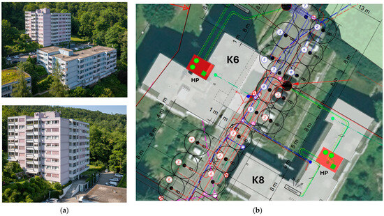
Figure 1.
Pilot plant of the dual-source HP boiler replacement. (a) View of MFH K6 (light pink building in the back) and K8 (light blue building in the front), top, and MFH K6 and the parking lot for the installation of the BHX field, bottom. (b) Final layout of the reduced BHX field. The blue numbered ground probes belong to K6 and the red numbered ground probes to K8. The red rectangles indicate the position of the cellar rooms where the heat pumps are installed.
A boiler replacement using one HP per building with a shared BHX field was planned, which significantly improves the energy balance and lowers CO2 emissions of the buildings. However, due to the steep terrain and access for the drilling rig, the space for the drilling of the BHX is restricted to the parking lot.
Due to these constraints, additional regeneration using an air heat exchanger (AHX) was planned. The choice of the regeneration source fell on an AHX, since a roof renovation is planned in a few years and therefore no solar technologies can be installed at present. The planned future roof renovation will serve to further improve the energy quality of the buildings and possibly retrofit a PV system. However, the drilling of the first two boreholes at the planned depth of 290 m had to be stopped at a depth of 130 m due to artesian water. Therefore, in addition to the space restriction, the cantonal authorities restricted the drilling depths to 120 m.
This new situation presented the following challenges for the continuation of the boiler replacement:
- Redesign during the ongoing construction project.
- The HPs had already been ordered, a change in the order would have resulted in high costs and delays.
- The use of the roof is notably restricted due to planned roof renovation in a few years.
- The space available for the BHX and the drilling depth restriction.
Due to these constraints, a dual-source concept with peak load coverage by the BHX field and extension of the already-planned AHX to cover the base load as investigated in the simulations has been considered.
2.2.2. Redesign of a Dual-Source HP System
Based on confirmed feasibility by simulations, which are presented in Section 3.2, the system choice fell on two indoor installed propane HPs. Considering the boiler efficiency (approx. 20% losses) and pipe losses of MFH K8 (approx. 7%), an energy demand of 446 MWh or 106 kWh/(m2 year) was taken as basis.
The design heat load has been evaluated by measurements in the two houses in the coldest week of January 2023 with clamp-on heat meters. Results have been transformed by the energy signature method to find the design heat load at the design outdoor temperature of the site of −8 °C. Additionally, the DHW load and defrosting expenses have been added. The DHW load was recalculated from the DHW demand according to Swiss SIA 2024 of 19.8 kWh/(m2 yr) and additional 50% losses as a maximum defined in SIA 385/2 [31], including circulation, storage and distribution thermal losses and also electric expenses. The defrosting was estimated by assuming a 50% source capacity of the AHX at the coldest day and with 15% of the heating energy used for defrosting. Blocking times of the utility for the HPs, which refer to remote cutting-out of the HP operation by the utility for load management and grid stabilization purposes (common in Switzerland since the 1990s), are contractually limited to a maximum of 3 times a day for 2 h each. For allowing the remote control, users are often rewarded by special HP electricity tariffs. However, these blocking times are not applicable at the site. The derived design values and the effective design of the HPs are summarized in Table 3. The heat demand has been determined using the same area-specific values based on the oil consumption of the boiler operation, which supplied both buildings. However, since the energy reference area is larger for K6 than K8, the absolute heat demand in MWh has been derived by multiplying the specific value with the respective energy reference area. As such, the heat load differs between the two buildings due to the different size.
Table 3.
Design parameters of the HPs for boiler replacement.
The separate HPs and hydraulic circuits depicted in Figure 2a comprise two separate hydraulic circuits that are coupled by a plate heat exchanger. In regeneration mode, this is coupled by means of a 3-way changeover valve. Table 4 shows the test points of the HP performance map.
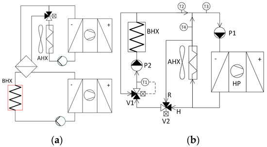
Figure 2.
Hydronic integration options for the dual-source HP. (a) Separate HPs and separate hydraulic circuits; (b) both sources, AHX and BHX, integrated in one hydraulic circuit.
Table 4.
HP Characteristic at different test points for the HPs SW114/2 FU-A/SW89/2 FU-A.
In the redesign phase, two hydronic integration concepts were discussed, which are depicted in Figure 2.
The advantages of this integration encompass a clear separation of the two systems, without a risk of undercooled BHX inlet temperatures occurring with cold outdoor air temperatures, a simple control and a lower glycol content in the BHX cycle than in the air cycle, which implies cost savings. However, the drawbacks include temperature losses over the plate heat exchanger and the power shares of the two systems being limited by the HP capacity and uneven running times.
If the AHX and BHX are integrated in one hydraulic circuit, as shown in Figure 2b, the two sources are connected in the same hydraulic circuit to an HP.
In regeneration mode, the BHX field is coupled downstream of the AHX by means of changeover valves, which has the advantages of more flexibility, since the capacity of a source is not limited by HP capacity. Only one HP is required, and no losses due to temperature differences in heat exchangers during regeneration occur, which means that higher regeneration rates are achievable. Nevertheless, the disadvantages are that the BHX must be protected from cold temperatures from the AHX, which makes the control more complex, especially for the mass flows. Exergy losses occur due to mixing at cold temperatures, and the overall performance of the HP is lower at cold temperatures, as the evaporator inlet temperature is lower. Since more valves are required, the costs tend to increase.
Due to the advanced stage of planning and the fact that the HPs had already been ordered at the time of the project change, it was decided to build the system as an integrated circuit. This variant is also hydraulically closer to the originally planned variant with the AHX for regeneration. The exergy loss at cold temperatures occurs when the outlet temperature from the BHX is higher than the outlet temperature from the AHX, i.e., the source temperature from the BHX is mixed down.
The control strategy consists of several modes. The combined-source mode is activated when the outdoor air temperature decreases below 6° C. The control strategy for the dual-source mode is based on PI control. The control output is the BHX mass flow (signal to pump P2 in Figure 2b). Table 5 describes control strategies that have been evaluated (CS2 and CS3 in simulation, see Section 3.2.2, and CS3 and CS4 in the pilot plant, see Section 3.3) and the corresponding control variables.
Table 5.
Control strategies for combined-source mode related to sensors in Figure 2b.
In all combined-source modes, the BHX minimal temperature controller is active to protect the ground from freezing. It controls valve V1, which mixes the BHX return temperature back to the BHX supply temperature and keeps T1 above a certain level if the outlet from the heat pump is too cold. In regeneration mode, valve V2 is switched from H to R; therefore, part of the AHX return flow, which is not needed in the heat pump, flows through the BHX for regeneration.
2.2.3. Installed System Configuration
The HP system in both houses is identical except for the heating capacity, see Table 4 for the technical data. Figure 3 shows the two HPs and AHXs. In K6, the AHX was placed on a plinth in the garden, and in K8, it is mounted on the lift superstructure. The roof has already been renovated in this area, so the AHX no longer needs to be removed when the roof is renovated later. The HP consists of the following modules:
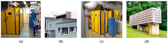
Figure 3.
Installed dual-source HPs and AHX. (a) Indoor installed propane HP in K8; (b) AHX installed on the lift superstructure on the roof of K8; (c) indoor installed propane HP in K6; (d) AHX installed on a plinth in garden of K6. The two-stage, speed-controlled brine-to-water (B/W) HPs each consist of three parts, which are each housed in their own enclosures, see Figure 4.
- Control cabinet.
- Capacity module in ventilated housing for the refrigerant circuits, see Figure 4, depicting the two capacity modules. Each capacity module comprises two separate refrigeration circuits, each with a speed-controlled compressor by inverter.
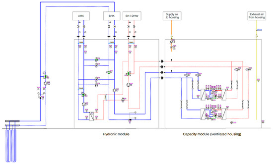 Figure 4. Hydronic sketch of the hydraulic module and the capacity module of the installed HPs. Blue lines: source circuits; dashed blue line: return flow; red lines: sink circuits; dashed red lines: return flow; yellow: supply air; green: exhaust air.
 - Hydraulic module, which contains the hydraulic components such as valves, pumps and plate heat exchangers.
The following operating modes are implemented in the hydraulic modules:
- Heating/DHW with outdoor air as source.
- Heating/DHW with ground probes as source.
- Heating/DHW with outdoor air and ground probes as source.
- Regeneration without HP operation.
- Regeneration with HP operation.
- Defrosting.
The BHX extends on the parking lot between K6 and K8, see Figure 1, and contains the following:
- Building K6: 8 probes of 100 m each + 1 probe of 106 m = 906 m in total.
- Building K8: 7 probes of 100 m + 1 probe of 86 m = 786 m in total.
The operating concept corresponds to the developed “peak load coverage” strategy, see Section 3.1.1, extended to include ground regeneration. It is operated with the following basic control strategy.
- Summer: AHX source.
- Winter: Base load AHX, peak load BHX.
- Regeneration: Whenever possible, the ground is regenerated using the AHX.
All ground probes are double U-tube probes with a DN 40 pipe diameter, 132 mm borehole diameter and grouting with Bentonite. The distance between the probes is 8 m. The probes in the BHX field are connected in parallel from a common collector. Due to thorough design of the probe diameters with respect to the volume flow, the pumping expenses in terms of energy use and cost can be limited. The BHX fields are switched on dynamically and are dependent on the heat load, as described in Section 2.2.2. Section 3.1.2 shows the results of the simulations for different control strategies. One of the objectives of the P&D plant is to test and improve these control strategies, e.g., to control the extraction of heat from the ground depending on the “state of charge” of the ground, i.e., taking into account the amount of heat rejected and extracted.
2.2.4. P&D Objectives and Monitoring Equipment
Based on the simulation results, the P&D project thus offers ideal conditions for verifying the simulation results with real measurements. Operating experience can be gained with the real plant operation of the dual-source system, and design and control strategies for operation can be tested and verified. The project objectives therefore include the following items in detail:
- Verification of the concept of the peak load ground source over the complete project phases “planning–commissioning–monitoring–optimization”.
- Review of the planning principles and hydraulic integration.
- Evaluation of 3 years of operation (optionally also longer measurements).
- Model validation with operating data and system optimization.
- Optimization of source management (e.g., by means of setpoint shifting: dynamic balance point, combination with summer regeneration, etc.).
- System comparison abstracted from the real boundary conditions in order to verify whether multi-source systems can also offer advantages for cases without heat source limitations.
Based on these objectives, different key performance indicators (KPIs) and a respective measurement concept for their evaluation and verification have been elaborated. Table 6 summarizes the derived KPIs and corresponding measurement values as well as the applied device.
Table 6.
KPIs and required measurements for the evaluation.
The measurement concept depicted in Figure 5 includes heat meters for the individual heat sources of the ground probes and the air source as well as for the heat emission side and electricity meters for the HP and the auxiliaries.
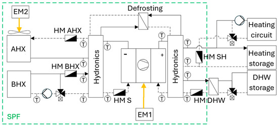
Figure 5.
Sketch of the measurement concept. The abbreviations are detailed in Table 7.
In addition, the operating states such as the compressor speed and pump status as well as the valve positions are recorded. Table 7 gives measurement points and the associated sensors. The measured variables can be used to evaluate the SPF, the source shares, the defrosting operation of the AHX and the degree of regeneration for the BHX, and respective optimizations can be made.
Table 7.
Measurement points and associated sensors.
2.2.5. Representativeness and Limitations of the Case Study
The representativeness of the case study is given by the following considerations:
- Typical building stock buildings with only slight renovation and oil boiler heating system before the retrofitting. This corresponds to the situation of almost 40% of the Swiss building stock.
- The buildings are not located in the city center but nevertheless experience similar limitations as in a densely built area due to the steep surrounding terrain and limited space of the parking lot available for the ground probes. Due to the artesian water, additional limitation of the drilling depth occurred.
- The buildings have typical radiator emission systems, implying higher supply temperatures in the range of 60 °C. The stock building also implies typical DHW share in the range of 20% of the total heat demand.
- By the combination of the presented strategies, the effects of both strategies of peak load coverage and regeneration can be evaluated in the same pilot plant. However, it is intended to consider the combined operation, which seems to be more favorable regarding the existing limitations of both heat sources, in particular the ground probes, which are significantly shorter than originally planned.
- The site exhibits typical ground parameters and the representative climate for the Swiss midland. The site is only about 20 km away from Zurich, which is often used as a reference climate.However, this also leads to some limitation of the chosen P&D plant:
- The evaluation is limited to the site in the Swiss midlands and is thus not representative for other sites in more mountainous areas. However, the densely populated areas are in the Swiss midlands.
- The system layout is fixed by the installed systems, i.e., no variants regarding design of the source system can be verified, e.g., in terms of probe number, probe distance and probe depth. The system, though, has been adapted to the limitations of the site, and the resulting system layout is thus a typical compromise based on the boundary conditions and reflects typical practical limitations for many sites.
- The load conditions are also fixed by the connected buildings and cannot be arbitrarily varied. In particular, the results are not directly transferable to new buildings with different load conditions, in particular a higher DHW share. Nevertheless, the limitations are more critical in the case for the building stock due to higher space heating loads in wintertime, since new-built buildings have better insulation.
- Also, the regeneration source is fixed to outdoor air regeneration, which has different characteristics to solar regeneration, which is also often applied. But solar regeneration is often also limited, e.g., by unavailable roof areas in existing buildings.
Summarizing, even though there are naturally limitations of the pilot plant related to the system configuration and the site, the results of the P&D project can be used to verify different aspects evaluated in the simulation study and cover some application cases for the existing building stock.
2.3. Indoor Installation of HP with Propane Natural Refrigerant
A further research aspect of the P&D project is the investigation of the technical planning and installation as well as the operational behavior of indoor installed HPs with a propane refrigerant in the higher capacity range. In the P&D plant, the nominal capacities of the HPs are 90 kW and 74 kW for the two buildings, respectively, cf. Table 3.
2.3.1. Characteristics of Propane and Other Refrigerants
A comparison of different refrigerants is given in Table 8.
Table 8.
Overview of characteristics of common refrigerants.
Fully (CFC) or partially (HCFC) halogenated chlorofluorocarbon refrigerants have been banned in new installations in the EU for over two decades due to their ozone depletion potential (ODP) based on the Montreal Protocol. The successor hydrofluorocarbons (HFCs) are chlorine-free but currently regulated due to climate impact, as denoted by their Global Warming Potential (GWP) by the Kigali Amendment to the Montreal Protocol and F-Gas Regulation of the EU. The currently offered substitutes hydrofluoroolefins (HFOs), also denoted as “low-GWP refrigerants”, are in discussion due to the formation of trifluoroacetic acid, which then forms trifluoroacetate (TFA) in water and on the ground. It is washed out of the atmosphere and accumulates in terminal water bodies and eventually groundwater [32]. Thus, natural refrigerants, which exhibit a low GWP and are exempted from present regulations, are becoming increasingly important as environmentally friendly refrigerants in refrigeration technology, which, however, have requirements regarding flammability, denoted by “A” in the safety group according ASHRAE, and toxicity, denoted with “B” in the safety group. Propane (R-290) has a low GWP of only 3 and no ODP. Another advantage of propane is its high thermodynamic efficiency and the possibility of achieving higher condensation temperatures up to a range of 75 °C, which favors its use in heating replacement or hot water production.
Despite its flammable properties, it is in safety group A3, which requires special safety precautions, and propane is increasingly being used in various applications. For instance, for building heating systems, outdoor air-to-water HPs using propane are becoming popular. Indoor brine-to-water HPs using propane are still less common, as the required safety measures are more complex than for outdoor installations. The two other natural refrigerants ammonia (R-717) and CO2 (R-744) have a similarly low GWP to propane and can also reach a higher temperature level. Ammonia, though, is toxic and thus also requires similar safety measures. Ammonia is often used for high capacities in heating centers in district heating applications up to the MW range. CO2 has a very low critical temperature and henceforth is often applied in transcritical cycles. For high performance, a large temperature spread in the gas cooler is crucial, which makes it a favorable refrigerant for DHW generation, but due to the limited temperature spread of space heating systems in the range of up to 20 K, it is less beneficial despite the high reachable temperature level. However, there are projects investigating the integration of space heating and DHW (e.g., [33]) to achieve a larger temperature spread on the sink side.
2.3.2. Safety Concept
For the P&D project, the experiences and lessons learned during the implementation and operation are evaluated. The safety concept in the P&D plant is based on CEN standard EN 378 [34] and the Swiss SUVA regulations 66139 [35] (older versions in the contract). The safety concept can be divided into different types of measures:
- Technical measures (T).
- Structural measures (M).
- Organizational measures (O).
Regarding the technical measures, the HP is installed in a ventilated installation room. In addition, the refrigeration circuit is housed in a separate ventilated enclosure. A fan (explosion-protected) extracts the air from the housing and the room, i.e., there is always a negative pressure difference in the housing and the room relative to the respective surrounding. The negative pressure and the air flow rate are monitored, and the pressure difference is regulated to at least 20 Pa. A refrigerant detector monitors the propane concentration in the housing and triggers an emergency when exceeding 20% of the lower explosion limit (LEL). Further measures are necessary to ensure that propane cannot enter the room via the safety valve or automatic vent by a leak within the evaporator and condenser. Therefore, specifications define no automatic vents and safety valves in the heating and brine circuit connected to a vent pipe leading to the outside.
Regarding building measures, the exhaust air pipe from the housing must be routed to a location where the propane cannot cause damage. The air inlet into the installation room must be positioned so that there is good air flow in the floor area of the installation room, as propane is heavier than air and collects on the floor in the event of a leak. This must also be considered for the outlet so that the propane cannot collect in a depression under the outlet. The air outlet can be located close to the floor, but it must be ensured that it cannot be covered (e.g., by snow or objects). Note that the entire exhaust air duct is kept under negative pressure and the fan is placed directly in the air outlet and protected with an insect screen. The entire exhaust air duct must be made of metal and grounded. For the P&D, a safety zone (EX zone) of 3 m around the outlet was designed with no windows or ignition sources. When propane escapes, it mixes very quickly with air so that no flammable mixture is formed. People are allowed around the air outlet, but ignition sources are prohibited, similar to filling stations. The zone must be marked with warning and prohibition signs.
The organizational measures cover the various processes from planning to disposal. In planning, the safety concept must be drawn up at an early stage. This is used to derive a risk assessment that considers the requirements of the relevant standards and the specific implementation. The risk assessment is continuously updated and discussed with the planner, installer and architect. Regarding installation and commissioning of the HP, it must be ensured that the propane only enters the building once the ventilation system has been installed and is in operation. The device is therefore separated into several units (capacity module with refrigeration circuits with ventilated housing, hydraulic module and control cabinet, see Section 2.2.3). The preferred option is to install the refrigeration circuits in the capacity module after all other systems and the ventilation are operated, which, however, requires sufficient space to be available for the installation. For boiler replacement, this is often not the case due to limited space, as also in the P&D plant. In case of a lack of space, there is a risk of damage to the refrigeration cycle during transport. In the P&D system, the refrigeration circuits were filled with propane onsite with an exhaust air system, with the disadvantage that propane had to be handled onsite. For the operation phase, the installation room is only accessible to authorized persons. All maintenance work must only be carried out by trained personnel. The operator is obliged to organize the maintenance and servicing. For decommissioning, the refrigeration circuit must first be completely emptied, vacuumed and flushed with nitrogen before switching off the exhaust air system. The refrigeration machine oil in the compressor may outgas the still-contained refrigerant; thus, the emptied, open refrigeration circuits shall only be stored outdoors.
3. Results
The investigation of the dual-source HP system was initially carried out by simulation. The high practical relevance of limitations on the available heat sources in retrofitting projects with real constraints of the built environment was confirmed by the fact that during the project phase, a retrofitting project of two larger MFHs has already been identified, which offered ideal conditions for the application of the simulation results in a real application. In the following sections, the results of the simulation are first described, and afterwards, the monitoring results of the first winter period of the P&D plant are discussed.
3.1. Simulation Results
3.1.1. Results of the Strategy “Peak Load Coverage”
The strategy “peak load coverage with BHX” has advantages in cases with capacity limitations of the primary heat source, as it can avoid extensive noise emissions of the outdoor air heat source. On the other hand, for a BHX-only system, there may be space restrictions for the installation of a sufficient number of probes or drilling depth restriction. Figure 6 shows the relative probe length compared to a 100% BHX heat source. The parameter variations according to Table 2 were simulated. Due to the peak load coverage, both AHX and BHX sources can be designed smaller, e.g., to 50% of the required source capacity, which alleviates both the restrictions for the air and the ground.
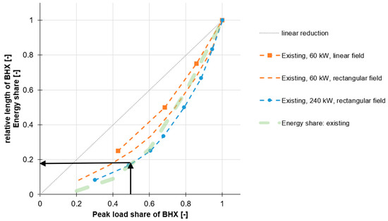
Figure 6.
Parameter variations for the strategy “peak load coverage”. The arrows indicate that a design of 50% capacity enables downsizing of 80% of the total borehole length as reading example.
Figure 6 summarizes the basic results of the simulation variants for existing buildings.
The variations showed a robust behavior, which simplifies the design for different boundary conditions. The biggest difference, as depicted in Figure 6, has been found in the probe arrangement of the BHX between a line field and compact rectangular field on the one hand and the building size, and thereby the BHX field size, on the other hand.
The rectangular field shows a higher degressive behavior, in particular for higher capacities, as the natural regeneration is limited by the mutual influence of the probes (field effect) and a reduction in the length/number of probes, and a lower load in the peak load case has a higher impact. With the combination of AHX as the primary source and BHX for sole peak load operation, significantly less energy is extracted from the BHX than with BHX-only operation, which is depicted by the green line in Figure 6.
As a result, the totally installed probe length can be reduced disproportionately, which further helps to overcome space restrictions that exist in particular in existing buildings. In the case of compact borehole heat exchanger fields, the reduction in probe length corresponds approximately to the energy extraction from the field, e.g., approx. 20% of the total source energy when designed for 50% of the total heating capacity, as depicted by the arrows in Figure 6. The simulation results also confirm performance advantages through better winter source temperatures compared to AHX-only operation.
In the simulations, the seasonal performance can be increased from just below 3 (AHX-only) to 4.5 (BHX-only) depending on the proportion of capacity by the BHX. The differences between new and existing buildings are relatively small, as the lower heating temperatures in the new building are compensated for by the higher proportion of DHW.
Figure 7 shows the cost structure for an existing building of the building stock depending on the proportion of capacity covered by the BHX for the market situation as of June 2022.
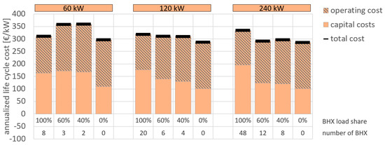
Figure 7.
Economic evaluation of the concept “peak load coverage”.
The economic evaluation is based on the boundary conditions given in Appendix A. The methodology is based on SIA 480 on investments in construction projects [36]. The net present values are calculated and transformed into an annuity, i.e., an annual equal cost over the whole lifetime of the systems. The total calculation period is equal to 50 years, the lifetime of the ground probes.
The percentual fraction given for the single bar refers to the fraction of capacity covered by the ground source, i.e., 100% refers to the ground as the only source and 0% to outdoor air as the only source. The fraction of 60% and 40% refers to the heat load which is covered by the ground source.
The depicted cost thus refers to the ground- and air source only as well as for the fractional percentage for the dual-source system consisting of the air- and ground sources. This is the reason why the system with three ground probes is more expensive than the ground source only system with eight ground probes for the capacity of 60 kW, since in the 60% configuration, the air source is also included.
For the individual sources, there are slight advantages for lower capacities of 60 kW. However, the additional costs for a dual-source solution are moderate at 50 EUR/kW and may enable the use of a monovalent HP, which might not be possible for the individual heat sources. At higher capacities, though, the cost advantages of individual sources are reduced or even reversed. In new buildings, there is additional free cooling potential by the BHX compared to an AHX-only system.
3.1.2. Results of the Strategy “Regeneration”
Regeneration is found most often for larger-borehole fields but mainly as solar regeneration. In this investigation, the main focus is set on the evaluation, how regeneration can overcome the space and depth limitations of BHX by use of an AHX regeneration source, since with regeneration, the probes can be arranged closer together and the total probe length can be notably reduced, which opens up options for more probes in less space or a reduction in the drilling depth. The reduction in the total probe length is due to a higher capacity of the inner probes, which are not regenerated naturally due to shielding from the undisturbed ground by the outer probes. Therefore, with technical regeneration, the capacity of the inner probes can be maintained, and thereby, the total size of the BHX field can be reduced. A second evaluation criterion is the cost for the “second”, i.e., regeneration source, particularly if a refinancing of the regeneration source is possible by savings in the BHX field, namely the trade-off between cost for the regeneration and degree of regeneration is evaluated.
For regeneration, uncovered solar collectors (USCs), PV/T collectors and AHX were systematically analyzed in parameter variations for different building sizes, probe field sizes, drilling depths, probe spacing and probe arrangements in the field. The probe arrangement refers to rectangular fields, where the number of probes in both directions is denoted as 8 × 6 for a field composed of 48 probes arranged in 6 rows with each 8 ground probes. The results show that regeneration achieves economic benefits by reducing the required overall probe length, thus avoiding space and drilling depth restrictions. Furthermore, in many cases, the cost savings can refinance or even overcompensate the investment costs of the regeneration source. In the case of solar regeneration, for example, a cost-optimized design can be achieved as a ratio between collector area and saved probe length.
The cost-optimized degree of regeneration of different parameter variations was in the range of 40–80%. It was also confirmed that the effectiveness of regeneration increases with larger fields and smaller probe spacing.
Based on the results of the parameter variations, a new diagram was developed that shows the necessity, i.e., if the BHX can be operated without regeneration for a given area and depth or if regeneration is necessary due to space and depth restrictions, and the cost-effectiveness of regeneration, i.e., if the investment for regeneration can be refunded through cost savings in the BHX field, respectively. Figure 8 depicts the cost field dependent on the regeneration rate for the given boundary conditions of the heating capacity requirement (e.g., 240 kW in this depiction) and the regeneration source (e.g., PV/T in Figure 8a on the left and USC in Figure 8b on the right) for the specific site area in [m2/kW] for the parameter of the drilling depth.
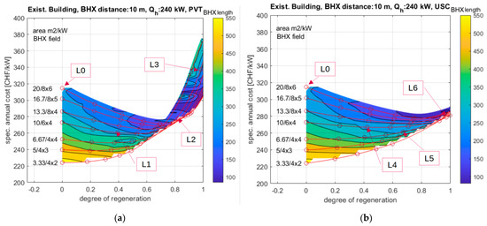
Figure 8.
Annual cost dependent on the degree of regeneration. (a) Regeneration source PV/T, (b) Regeneration source USC.
In the cost fields of Figure 8a,b, different points are marked, which are compared in Figure 9 as examples. These points are L0 (reference case without regeneration) and L1–L6 with the different regeneration sources and shares. The cost values depicted are the life cycle cost of the system consisting of the net present values (NPVs) of the investment cost and discounted maintenance cost (CAPEX), the operational cost (OPEX) and earning of systems with PV yield. The NPV is transformed into an annuity of evenly annual specific cost in [€/kW], where PV earnings by the feed-in tariff of grid export are subtracted to display the total cost. Boundary conditions for the economic evaluation are given in Table A1 in Appendix A. The results for the annuity are compared in Figure 9 for the different investigated systems. Below the cost bars, the number of probes and the regeneration rate in [%] are displayed to demonstrate the reduction in probes for a given amount of regeneration, which is reflected in the investment and operational costs.
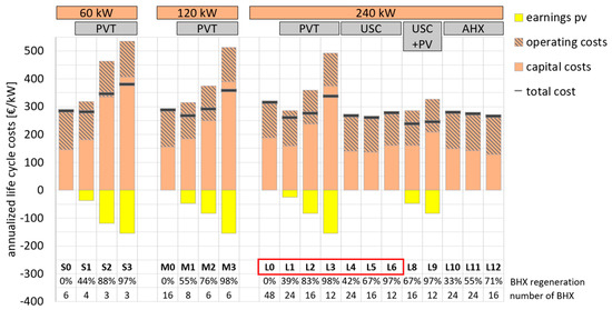
Figure 9.
Economic evaluation of regeneration. For the USC + PV variants, cases L1 to L6 marked with the red box correspond to the marked position in Figure 8. For the USC, the same roof area as for the PV/T was used, but the roof area that is not used for the USC due to the higher thermal yield was covered with PV.
The form of the contours depicted in Figure 8 already shows that a high degree of regeneration approaching 100% increases the total cost of the system due to increasing cost for the regeneration source, while cost-optimal cases are found in the mid-range of 40–80%. This is also shown in Figure 9 for the distinct cases L1–L6 for the two regeneration sources of the PV/T and USC.
The specific annual costs of different system variants with and without regeneration confirm that above regeneration rates of 40–80%, there are no major changes in the number of ground probes, but the required regeneration area and the costs of the regeneration source increase sharply, in particular for PV/T collectors. On the other hand, moderate regeneration in the cost-optimal range lowers the total cost, in particular for larger capacities, which confirms that larger rectangular BHX fields without regeneration are economically inefficient. In this evaluation, the lowest costs are achieved with the USC combined with PV, although the considered systems of a regeneration by PV/T and USC collectors as well as AHX do not differ much. The PV is installed on the remaining area that the USC does not use compared to the same area of PV/T collectors due to the higher thermal yield of the USC.
The economic superiority of individual depicted solutions, though, is also strongly influenced by the cost parameters (drilling costs, tariff structure, component and system costs, interest rate, etc.). The respective assumptions are given in Appendix A.
Moreover, the degree of regeneration on the x-axis in Figure 8 can also be interpreted as a distribution between two sources, which means that this visualization can also be used for other systems, such as the “peak load coverage”.
Summarizing, the results confirm that regeneration achieves economic benefits by reducing the required overall probe length, thus avoiding space and drilling depth restrictions. Furthermore, in many cases, the cost savings can refinance or even overcompensate the investment costs of the regeneration source. In the case of solar regeneration, for example, a cost-optimized design can be achieved as a ratio between collector area and savings on probe length. The cost-optimized degree of regeneration of different parameter variations was found in the range of 40–80%. It was also confirmed that the effectiveness of regeneration increases with larger fields and smaller probe spacing.
Figure 10 illustrates the required space for the BHX for a heating capacity of 240 kW if a borehole depth of 280 m is possible. As a reference case for the space requirement without regeneration, 40 ground probes in a 10 m spacing are set, i.e., a space of 4000 m2 is required. Variations have been evaluated regarding the probe spacing and the degree of regeneration. If the area for the BHX is not limited, a spacing of 20 m is possible without regeneration. Due to the better natural regeneration, the total length of the probes can be reduced to 56%.
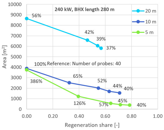
Figure 10.
Possible area reduction based on regeneration share for different ground probe distances.
With the larger spacing between the probes, the regeneration is less effective, since with a regeneration rate of 50%, the total probe length only decreases from 56% to 42%. Also, with higher regeneration rates, the total probes length only decreases marginally.
With the reference spacing of 10 m, the regeneration becomes more effective, and the total probe length can be reduced, with a high regeneration rate of 80%, to about 40% of the original length. Thereby, the space for the BHX can be reduced by a factor of 2.6 to about 1500 m2, which means that space limits can also be overcome by regeneration. This effect is even more pronounced if the probe spacing is further reduced to 5 m. Without regeneration, the probe length would have to be notably extended to 386% of the reference case. Nevertheless, the regeneration is more effective, which is shown by the fact that with 40% regeneration, the necessary probe length is only 26% more than the reference value, but the required area can be reduced by a factor of 4 to about 1000 m2. With a higher regeneration rate of 80%, the total probe length decreases even more to 40% of the reference values, and the area can be reduced by a factor of 10 to about 400 m2. This means that with decreased spacing, regeneration can notably reduce the probe length and the space for the BHX, which opens up potential for retrofit projects with space restrictions.
3.2. Simulation Support for the Redesign to a Dual-Source System
3.2.1. Combination of Strategies
For higher capacities, a combination of the two strategies ‘peak load coverage’ and ‘regeneration’ may also be suitable.
As the number of probes is already significantly reduced by peak load coverage but the effectiveness of regeneration decreases with fewer probes, the combination only makes sense for higher capacities.
Regeneration ensures slightly higher operating performance and additional robustness of the design. Figure 11 shows the annual costs for the analyzed system with 240 kW heat output and 160 m deep probes. It can be seen that a big reduction in the number of probes is already achieved with the peak load operation.
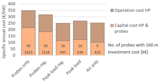
Figure 11.
Annualized life-cycle cost for the system with 240 kW in an existing building and 160 m probe depth.
The investment cost difference for peak load operation with or without regeneration is relatively small compared to the other cases, even though the capacity with 240 kW is quite high.
3.2.2. Simulation Results for P&D System Combination of Strategies
Due to the system size in the range of 200 kW, the approach of combining the two investigated strategies was also considered so that the AHX is still used for regeneration of the ground source during the transitional and summer period and combined with the BHX in peak load operation. To prove the feasibility of the dual-source concepts, parameter variations and tests of associated control concepts have been performed by simulations, also for the combined strategies of peak load coverage by the ground source and regeneration with the air source. Figure 12 summarizes the simulation results. A BHX-only source would require 14 ground probes of 400 m depth to fulfil the SIA 384/6 criteria not to surpass the lowest permissible average fluid temperature of –1.5 °C, as depicted by the black line in Figure 12a. For the initial planning with a BHX of 14 ground probes of 300 m each, regeneration with air would be required to meet the SIA criteria.
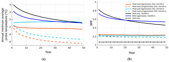
Figure 12.
Simulation results for the pilot plant. (a) Source temperature evolution over 50 years for different BHX depths, probe number and control; (b) SPF for the respective parameter variations.
However, due to the regeneration, the ground is not as exhausted and yields a slightly higher SPF, as seen in Figure 12b. For the depth of 120 m and only peak load operation of the ground, two control strategies have been tested. The first is a conservative control strategy CS2, which only uses the ground when the AHX-only system cannot provide the entire required source capacity. The second, CS3, denotes a more progressive control strategy, which has higher shares of BHX use to optimize the SPF, see also Section 2.2.2 and Table 5. It is clearly visible that without regeneration, the SIA criterion cannot be met independent of the control strategy. With regeneration, however, the criterion can be kept with the conservative control strategy CS2, while it is not reached with the progressive control strategy CS3. Moreover, due to the peak load operation, the BHX is operated colder than the deeper probes at 300 m, which decreases the SPF by about 0.4 points to 3.2. The temperature decreases right from the beginning, which is due to a higher-capacity extraction for the short-term peak load operation. An air source alone, however, would only reach an SPF of slightly above 3 and would be problematic to realize due to noise emissions from the much larger AHX that would be required.
3.2.3. Exergy Losses
The heat flows from the two sources are mixed in the integrated hydraulics, see Figure 2b. In this mixing process, exergy from the warmer source is destroyed, which must then be fed back into the HP in the form of electrical energy. The exergy content at the inlet to the evaporator in the integrated system and the total for the two evaporators in the separate system have been compared. The moving outdoor air temperature has been used as the reference temperature. The greatest exergy loss occurs in the period between 5 and 14 January. The difference in the exergy content of the evaporator for the two systems amounts to approx. 1.1 MWh over the year. This corresponds to the exergy loss in the integrated system compared to the separated system. This exergy loss must be fed into the system in the form of electricity for the higher compression of the refrigerant. Compared to the electricity input to the system in the range above 100 MWh, the exergy losses due to mixing are negligible.
3.3. Monitoring of Boiler Replacement by Dual-Source HP System
The simulation results are currently being verified in a real application in the pilot and demonstration project described in Section 2.2. The focus of this evaluation is set on the first winter operation in the heating period 24/25, which was characterized by a December with temperatures generally in line with the 1991–2020 average. In January 2025, however, an average temperature of −0.8 °C was recorded, which is 1.4 °C above the 1991–2020 average, marking one of the warmest Januarys on record. The unusually high temperatures can be attributed to mild air influx from the west and southwest. The recorded daily maximum values for the specific locations significantly surpass historical averages.
For the monitoring period of 1 October 2024 to 28 February 2025, the evaluated SH and DHW shares reflect typical fractions for existing buildings, with a share of 79% for SH and 21% for DHW, respectively. The space heating is operated at a supply temperature of up to 60 °C in the considered period, and the DHW is charged to 65 °C. The heat source energy is mainly covered by the AHX with a share around 90% and only about 10% by the BHX, which is on the one hand due to the mild January and on the other hand due to the conservative control strategy used until the end of 2024.
Figure 13 shows the thermal source power and temperatures for K6 with combined source control (CS3 according to Table 5) in more detail for a four-day period in January. On 21 January, the minimal inlet temperature to the BHX is set from 0 to −2 °C, as can be seen in Figure 13a.
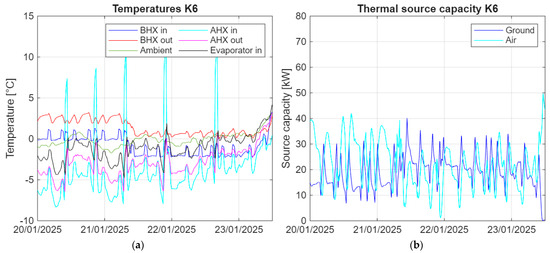
Figure 13.
Monitoring results of MFH K6 with combined source control. (a) Source temperatures of the heat sources, evaporator inlet and ambient air; (b) thermal source capacity by the AHX and the BHX.
The BHX source power in Figure 13b increases from around 15 kW to around 25 kW, while the AHX source power decreases from around 40 kW to around 20 kW. The evaporator inlet temperature, a mixture of both flows from BHX and AHX, increases from around 2 K below the ambient temperature to a value close to the ambient temperature.
The “AHX in” daily peaks are due to defrosting of the AHX. Due to the slightly different design of the source capacity in MFH K8, an alternate source control has been tested, i.e., either the AHX or the BHX is operated. This strategy could only be tested in K8 because the heat load is lower than in K6, whereas the AHX has the same capacity.
Figure 14 shows the temperatures and thermal source power for K8. In BHX-only operation, the evaporator inlet temperatures are significantly higher than during combined operation in K6, whereas they are significantly lower in AHX-only operation.
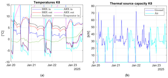
Figure 14.
Monitoring results of MFH K8 with alternate source control. (a) Source temperatures of the heat sources, evaporator inlet and ambient air. (b) Thermal source capacity by the AHX and the BHX.
During operation of the BHX, the outlet temperature decreases due to cooling of the ground. When reaching the minimum temperature at 2 °C, the source is switched to air. The difference in temperature between the BHX outlet with resp. to the AHX outlet and evaporator inlet during operation of BHX occurs from different positions of the sensors and can be neglected. Temperatures above 10 °C occur when the individual sources are not in operation or AHX is in defrosting mode and can therefore also be ignored.
In Figure 15a, the evaporator inlet temperature as a function of the outdoor air temperature for the different control strategies is depicted. Compared to AHX-only control, depicted in red, the evaporator inlet temperature can be increased in combined-source strategies, depicted in blue. The separate-source strategy compensates for the lower temperature with significantly higher temperatures in BHX-only mode, depicted in orange. In K6, operating only with AHX at very cold ambient temperatures leads to evaporator inlet temperatures that fall below the minimum permissible temperature limit for the HP.
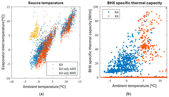
Figure 15.
Comparison of the monitoring results in MFH K6 and K8. (a) Source temperature of the combined operation in K6 and the alternate operation of the AHX-only and BHX-only in K8; (b) specific thermal capacity extracted from the BHX in combined (K6) and alternate (K8) control.
Figure 15b shows the hourly moving averaged specific thermal source capacity delivered by the BHX. The source capacities are notably lower in the combined operation in K6, depicted as blue dots, since, additionally, the source capacity of the air contributes to the total capacity required.
In K8, however, the BHX-only operation reaches extracted capacities up to 90 W/m due to the strategy of the alternate operation of the sources, which confirms that short-term extraction of higher capacities is possible without damaging the BHX.
The evaporator inlet temperature in K6 is around 1–2 K higher than in K8, increasing the PF around 0.2. From 25 December to 5 January, K6 runs on 30 to 50% BHX share, while K8 runs most of the time on BHX only, which leads to a higher PF. On 12 January, K8 does not run, and the evaporator inlet temperature is around the ambient air temperature (20 °C).
From 17 January to 22 February, data losses due to a fieldbus converter failure occurred, so no data of the electric meters in K6 were available and the PF could not be measured and evaluated. In parallel, from 12 February to 28 March, a problem in the refrigerant cycle occurred in K8, which notably lowered the measured PF, which is marked as the green area in Figure 16 (overlap with red area in the beginning). From mid-April, controller problems were encountered, first from 11 April with the fan controller in K8 marked as the blue area in Figure 16 and shortly afterwards from 15 April with the temperature data marked as the yellow area in Figure 16. Due to the longer interruption of measurements of electric energy in K6 as well as the refrigerant cycle problems in K8, no PF for the entire heating period could be evaluated.
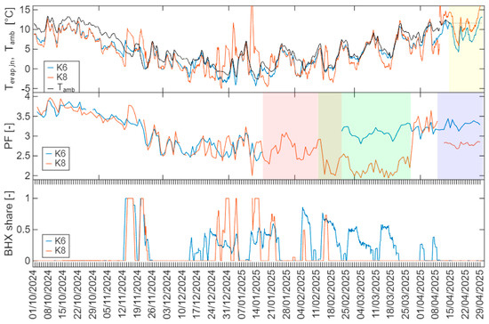
Figure 16.
Borehole shares, PF as well as evaporator inlet temperature and ambient temperature for the winter evaluation period 24/25. Red area: energy meter data missing due to a device failure in K6. Green area: low SPF in K8 due to a refrigeration cycle problem. Yellow area: temperature data error due to a controller problem. Blue area: Fan controller problem in K8.
4. Discussion
4.1. Simulation Results of Dual Heat Source Integration
The investigations carried out confirm the potential of multi-source integration to overcome the limitations of individual heat sources and to enable monovalent HP operation.
Furthermore, increased efficiency can be achieved by utilizing the best seasonal temperature conditions of the respective heat sources, i.e., preferably the ground in winter (peak load) operation and the outdoor air at favorable transitional and summer temperatures. Cost savings, in particular by reducing the overall length of probes in the BHX field, can compensate or even overcompensate for the costs of the second heat source, making multi-source solutions attractive even for applications without restrictions. This is especially the case for the higher capacity range, where the limitations on the heat source side may increase. Thus, the hypothesis could be confirmed by the simulation results.
The combination of heat sources is not limited to the combination of outdoor air and ground probes considered in this study. Rather, the outdoor air is representative of a source with limited capacity, which, whilst it may physically be considered an unlimited heat source, is limited due to noise protection requirements. The ground, in contrast, is representative of a storable heat source and thus can be regenerated but may also be restricted.
Other possible combinations comprise ground or surface water with a limitation due to the pumping volume or waste heat, e.g., from a commercial cooling process or industry, with capacity limitations in combination with AHX and/or BHX.
In the regeneration concept, the second source is principally used to manage the primary heat source that can be stored. In addition, however, the regeneration source can also cover, for instance, the summer operation as the sole heat source and thus utilize seasonal advantages, such as higher solar radiation available in the case of solar thermal regeneration or the higher summer outdoor air temperatures in the case of AHX. Thereby, the regeneration of the primary heat source is further promoted, since it is less used in summer operation.
Nevertheless, an increased complexity of the system must also be taken into account, which can cause higher costs. A means to avoid higher planning expenses is to standardize the integration of two or more sources by further research and demonstration projects, which can prove and advance the applicability in practice.
In some cases, the combination can also enable other operating modes, such as free-cooling operation as an additional utility of the BHX. The utilization of these free-cooling options, though, also depends on the installed emission system in the building, e.g., surface emission systems like floor heating or ceiling cooling installations or, with restrictions, convectors. These requirements traditionally limit the application to new buildings, since in existing residential buildings, mainly radiators are installed, and radiators alone do not have sufficient surface for free-cooling.
Monovalent HP solutions were analyzed as part of the study. However, the concepts of peak load coverage developed can also be useful for a combination with other heat carriers or heat generators. In the context of retrofitting of existing buildings, a combination with district heating could also be an interesting combination, in particular if the district heating grid has reached its capacity limit or uses fossil fuels as peak load coverage. Decentral HPs could be integrated in larger consumers and applied as peak load coverage in winter only. This limits the size of the BHX field according to the results in Section 3.1, and the load profile for the energy drawn from the district heating grid is thereby shifted towards more even base load fractions by the reduction in SH in winter and an overall increase in the DHW proportion. If the peak load for the grid is reduced, more buildings in base load operation can be connected to the grid in the existing layout, if the capacity otherwise used for the peak load can be shifted to the base load operation by covering the peak load with the BHX. The decentralized HP can be further applied in summer for cooling purposes, which can contribute to regenerating the BHX. This can also be amended by summertime regeneration with the district heating system, e.g., connected to the return water of the district heating. This means that district heating can be better utilized, and more buildings can be connected to existing grids without increasing the grid parameters like pipe diameter/generator capacity. In this way, more heat is available for applications with higher temperature requirements such as stock buildings. These aspects are investigated in an upcoming project [37].
Regarding the BHX, the design criterion according to SIA 386/4 has been applied, which implies a time horizon of 50 years. However, during this long period, the load conditions considered during the design phase can change, e.g., by building envelope renovation measures or due to changing outdoor conditions and reduced heat loads by changes in the use of the building. If these aspects can already be anticipated during the design phase, the BHX design can be adapted and downsized, which offers further cost saving potential.
Due to multi-source integration, flexibility is created, whereby the share of the different heat sources can be varied depending on the current load situation with the potential of higher energy performance, for instance, the BHX being used more with decreasing load over the time horizon of 50 years.
Furthermore, sharing the heat source capacity among different sources can also relax the “stress” due to extensive use of an individual source.
In Zurich, for instance, a discussion is already ongoing as to how far the ground can be used sustainably in areas with high installation rates of ground-source HPs. Adding additional heat sources in combination with the BHX can offer a more sustainable use of the ground through the above-investigated strategies of limiting the ground use to either the winter peak load period or regenerating the ground during summertime—or both.
4.2. Monitoring Results of the Dual-Source HP Operation
The pilot plant measurements were started in the heating period 24/25. The first monitoring results of the winter period confirm that the system can cover the heat load despite the notably smaller design of the BHX field. Due to the conservative control strategy giving preference to the air source until the end of 2024 and a mild January 2025, the fraction of the ground heat source is still limited and holds potential to be used earlier and more frequently. The design of the dual-source HP system is thus feasible despite the redesign during the ongoing planning process and the limitations both on the ground and the air-source side.
However, through the option to operate building K8 in an alternate mode, it could also be verified that the ground probes can deliver higher source capacity in short-term usage in the case of a BHX-only heat source, as depicted in Figure 15b. This corresponds to the results of the simulations, which enables a significant reduction in the BHX field size when considering only temporary use at peak load, which helps to overcome the space limitations often encountered in retrofit applications. In peak load operation, only a small amount of energy is extracted, as shown in Figure 6, and the boreholes are only operated for short periods at a higher capacity but have a long time to regenerate during the off-peak time, since peak load only occurs during the coldest period. This implies the cost savings found in the simulations, as depicted in Figure 7, which can compensate the investment in the second heat source in the dual source configuration that covers the base load. These preliminary results will be further investigated in the following heating periods. One objective of the P&D project is to develop and evaluate monitoring measures of the ground temperature to control the extraction in the case of higher ground capacity and to prevent overuse of the ground or damage to the probes, respectively.
The performance factor of the winter period of the monitored system depicted in Figure 16 could not entirely be evaluated due to temporary failures in the monitoring equipment and the problems in the refrigerant cycle, as described above. In October until mid-November, the HP is only operated with the air source at still high outdoor air temperatures and evaporator inlet temperatures in the range of 5–10 °C. The resulting PF is in the range above 3 to almost 4.
The PF in December and January is in the range of 2.5 to 3 and is thereby still moderate. This can be explained by the evaluation of the core winter period and currently high fraction covered by the AHX, which, particularly in the core winter month, yields only low source temperatures. Moreover, the system is applied in a retrofit case with higher supply temperatures for SH and DHW. The system has not yet been operated with optimized ground source fractions, so there is also potential for an increase is the performance factor in winter operation.
Summarizing, the monitoring data of the first winter period of the dual-source HP operation confirm the conclusions of the simulation study, enabling source limitations to be overcome, which are particularly common in retrofit situations due to constraints by the built environment. The dual-source application enables HP-only boiler replacement without any back-up heater, in particular without fossil fuel use, which is an important result to achieve maximum decarbonization through the use of HPs. Future tasks are the direct comparison and validation of the simulations with monitoring data to verify and approve the models used in the simulation study as well as an economic comparison to the original concept and other possible options for retrofit applications. This also includes application cases without limitations. Furthermore, the measurement of further heating periods offers the possibility to vary the control by shifting the application of the heat sources, i.e., to a high fraction of the BHX in order to evaluate effects on the SPF, e.g., according to control strategy C4 in Table 5.
More generally, the results indicate that individual heat sources can be economically inefficient, especially for the larger capacity range, and that better system solutions regarding performance and cost can be developed using dual- or multi-source integration, also enabling monovalent HP operation. This shall be further investigated in order to advance knowledge for the planning process of more standardized multi-source system integration and to create more reference or best-practice applications, which are currently still scarce.
In terms of CO2 savings, a detailed evaluation has not yet been included, since the seasonal performance could not be evaluated for the entire heating period due to the failures in the measurement equipment. However, a preliminary comparison based on an approximated performance factor of 3 for the heating period can be estimated. This is a conservative estimation, since the results of the core winter with the worst conditions for the heat pump performance during the first winter were used, cf. Figure 16.
Table 9 summarizes the former CO2 emissions with the oil boiler operation and the new CO2 emissions with the heat pumps. The emissions factors for Switzerland are taken from KBOB [38] for scope 1–3 (onsite emissions, including supply chain of the energy carrier) as emissions factors for heating-oil-type EL and Swiss consumer mix electricity. This preliminary comparison yields CO2 savings of about 90%.
Table 9.
CO2 emissions by the different heating systems.
5. Conclusions
A dual source heat pump configuration has been investigated with the main focus on overcoming source limitations for the larger capacity range due to the built environment, which is a typical situation for boiler replacement through heat pumps in densely built urban areas. Thereby, the focus has been set on the two most commonly used heat sources in Switzerland, i.e., outdoor air and vertical ground probes, and two strategies of peak load coverage and regeneration, which both enable a notable downsizing of the individual heat sources by the dual-source configuration.
The strategies have been evaluated by simulation and in-field testing of two larger multi-family buildings, in which both strategies are combined.
The simulation results confirm that the strategies allow for typical limitations in terms of noise for outdoor air and in terms of space and drilling depth limitations for the vertical ground probes, which are both often encountered, to be overcome. This is achieved through the smaller capacity required from each of the individual heat sources. Both in terms of energy performance and life cycle cost, it was found that synergies among the sources can improve the overall energy performance and also hold economic benefits.
These results transcend the application only for cases with source limitations but also generally apply for the larger capacity range, where the use of only one individual source can be economically inefficient.
For instance, a larger compact rectangular BHX has an economic benefit when it is regenerated by a second (regeneration) source, since the capacity of inner probes is notably increased by the technical regeneration. It was found that savings on the BHX design surpass costs for the regeneration source, where the cost-optimal regeneration rate was found to be in the range of 40–80%. A focus in this study was set on regeneration with outdoor air, which may be most commonly available and can be exploited cost-effectively, while previously solar systems have been extensively used for regeneration [14]. However, costs do not differ much in the performed comparison. Solar sources, though, may also have limitations with respect to availability of respective installation space, e.g., availability of roof areas, shading and competition to other roof utilization as well as load-bearing or heritage restrictions. Moreover, AHXs are very compact and require little space compared to solar regeneration but may cause issues regarding noise emissions, as in the case of their use as the primary heat source.
The two strategies have been combined and implemented in a pilot plant, including a typical boiler replacement through heat pumps in the capacity range of 200 kW, which is thereby highly relevant to the decarbonization of the building stock throughout the coming decades. The first winter operation proved the functionality of the system configuration despite the notable reduction in probe length by about 60% as well as confirming the basic results found in the simulation. In particular, the short-term higher-capacity extraction from the ground of up to 100 W/mprobe could also be verified by the measured values, which enables peak load coverage with a smaller BHX design and, thus, cost savings compensating for the cost of a second source.
Due to device failure, the performance factor could not be evaluated for the whole winter period, but the fractured results point at a performance in the range of 3.5, which would be a good performance for retrofit applications with higher supply temperatures and better than to be expected by an outdoor air-only heat source. Even though the CO2 reduction evaluation is preliminary and does not yet precisely take into account seasonal effects of the CO2 content of the electricity mix as a result of the use of annual CO2 emissions factors, it demonstrates impressively that boiler replacement by heat pumps is an effective strategy for CO2 emission savings, in particular in the larger capacity range. Therefore, the dual-source configuration can be an enabler of monovalent heat pump operation to fully exploit CO2 saving potentials. As such, boiler replacements by fossil-fuel-driven systems should be avoided whenever possible.
Further work is dedicated to a thorough model validation by utilizing the monitoring data, the evaluation of the year-round performance, including the summer regeneration after the first winter period, as well as optimization potentials of the control and surveillance strategies regarding the heat extraction from the BHX.
Furthermore, comparison with other system configurations will be accomplished in order to assess benefits and drawbacks of the dual-source configuration in more detail. Another aspect relates to the further evaluation of the operation and performance of the indoor installed heat pumps with a propane refrigerant for retrofit application in the larger capacity range above 50 kW. Thereby, standardized system layouts can be derived and demonstrated in the frame of a real-world best-practice application.
Author Contributions
Conceptualization, C.W. and C.M. methodology, C.W. and C.M.; software, C.M.; validation, C.M.; formal analysis, C.M.; investigation, C.M.; resources, C.M.; data curation, C.M.; writing—original draft preparation, C.W.; writing—review and editing, C.W. and C.M.; visualization, C.M.; supervision, C.W.; project administration, C.W.; funding acquisition, C.W. and C.M.; All authors have read and agreed to the published version of the manuscript.
Funding
The research received funding from the Swiss Federal Office of Energy SFOE, grant number SI/502144-01 and SI/502598-01, and from Canton Aargau with the reference REF–60050051 FARO, 615-200015-02-13, which is highly acknowledged.
Data Availability Statement
The Carnot Blockset used for the simulation study is available at https://fh-aachen.sciebo.de/index.php/s/0hxub0iIJrui3ED (accessed on 20 August 2025). Data can be made available on request as far as no privacy issues are violated.
Acknowledgments
The collaboration in the P&D project with the partners Lägern Wohnen, Amstein + Waltert AG Zürich and Heim AG Heizsysteme as well as the project advising and supervision of the Swiss Federal Office of Energy SFOE is highly acknowledged.
Conflicts of Interest
The authors declare no conflicts of interest. The funders had no role in the design of the study; in the collection, analyses, or interpretation of data; in the writing of the manuscript; or in the decision to publish the results.
Abbreviations
The following abbreviations are used in this manuscript:
| AHX | Air Heat Exchanger |
| ASHRAE | American Society of heating, refrigeration and Air-conditioning Engineers |
| BHX | Borehole Heat Exchanger |
| CAPEX | Capital Expenditure |
| CEN | Comité Europeen de Normalisation, European Committee for Standardization |
| CFC | Chlorofluorocarbons |
| EM | Electricity Meter |
| ERA | Energy Reference Area |
| GWP | Global Warming Potential |
| HFC | Hydrofluorocarbons |
| HFO | Hydrofluoroolefins |
| HP | Heat Pump |
| HM | Heat Meter |
| KPI | Key Performance Indicator |
| MFH | Multi-Family House |
| NPV | Net Present Value |
| ODP | Ozone Depletion Potential |
| OPEX | Operational Expenditure |
| P&D | Pilot and Demonstration |
| PV | Photovoltaic |
| PF | Performance Factor |
| PV/T | Photovoltaic-Thermal collector |
| SAHP | Solar-Assisted Heat Pump |
| SPF | Seasonal Performance Factor |
| USC | Uncovered Solar Collector |
Appendix A
Table A1.
Cost assumption used for the economic evaluation.
Table A1.
Cost assumption used for the economic evaluation.
| Parameter | Specific Cost/Tariff | Remark |
|---|---|---|
| CAPEX | ||
| Air-source HP | 1700 EUR/kW | |
| Ground-source HP | 900 EUR/kW | |
| Borehole heat exchanger | 100 EUR/m | |
| PVT collector | 750 EUR/m2 | |
| Uncovered solar collector | 400 EUR/m2 | |
| Air heat exchanger (60–240 kW) | 1500–600 EUR/kW | |
| Maintenance | Dependent on capacity | Annual maintenance service abonnement |
| Additional cost of dual-source integration | 15 kEUR (60 kW)/ 30 kEUR (120 kW)/ 45 kEUR (240 kW) | |
| OPEX | ||
| Grid electricity tariff | 0.2 EUR/kWh | As of June 2022, strongly dependent on market |
| PV feed-in tariff | 0.10 EUR/kWh | As of June 2022, strongly dependent on market |
| PV self-consumption tariff | 0.17 EUR/kWh | As of June 2022, strongly dependent on market |
| Component lifetime/interest rate | ||
| Ground probes | 50 years | |
| Heating system components | 20 years | |
| Interest rate (real) | 1.5% |
References
- European Council: Fit for 55—Making Buildings in the EU Greener. Available online: https://www.consilium.europa.eu/en/infographics/fit-for-55-making-buildings-in-the-eu-greener/ (accessed on 20 February 2025).
- International Energy Agency. Wider Implications of Achieving Net-Zero Emissions In Net Zero by 2050, A Roadmap for the Global Energy Sector, Special report, revised version October 2021 (4th revision); International Energy Agency: Paris, France, 2021; p. 27. [Google Scholar]
- Romano, E.; De Sousa Fraga, C.; Hollmuller, P. CO2 emission savings of heat-pumps in the residential sector. Case study from multifamily buildings in Geneva. In Proceedings of the 13th IEA Heat Pump Conference, Jeju, Republic of Korea, 26–29 April 2021. [Google Scholar]
- Bundesamt Für Statistik. Available online: https://www.bfs.admin.ch/bfs/de/home/statistiken/bau-wohnungswesen/gebaeude/energiebereich.html (accessed on 20 February 2025).
- Swiss heat pump Association FWS. Heat Pump Market Development Switzerland 2024 and 4/2024; Swiss Heat Pump Association FWS: Zürich, Switzerland, 2025. [Google Scholar]
- Yang, L.W.; Xu, R.J.; Hua, N.; Xia, Y.; Zhou, W.B.; Yang, T.; Belyayev, Y.; Wang, H.S. Review of the advances in solar-assisted air source heat pumps for the domestic sector. Energy Convers. Manag. 2021, 247, 114710. [Google Scholar] [CrossRef]
- Namdar, H.; Rossi di Schio, E.; Semprini, G.; Valdiserri, P. Photovoltaic-thermal solar-assisted heat pump systems for building applications: A technical review on direct expansion systems. Energy Build. 2025, 334, 115516. [Google Scholar] [CrossRef]
- Tan, Y.; An, L.; Wang, L.; Hou, Z.; Zhao, S.; Liu, B.; Guo, Y. Proposal and performance evaluation of a solar hybrid heat pump with integrated air-source compression cycle. Energy Convers. Manag. 2024, 321, 119097. [Google Scholar] [CrossRef]
- Li, Y.; Cui, Y.; Song, Z.; Zhao, X.; Li, J.; Shen, C. Eco-economic performance and application potential of a novel dual-source heat pump heating system. Energy 2023, 283, 128478. [Google Scholar] [CrossRef]
- Reum, T.; Schmitt, D.; Summ, T.; Trinkl, C.; Ochs, F.; Schrag, T. Experimental analysis of parallel operation of two heat sources in a dual-source heat pump incorporating two compressors. Int. J. Refrig. 2025, 171, 124–138. [Google Scholar] [CrossRef]
- You, T.; Wu, W.; Yang, H.; Liu, J.; Li, X. Hybrid photovoltaic/thermal and ground source heat pump: Review and perspective. Renew. Sustain. Energy Rev. 2021, 151, 111569. [Google Scholar] [CrossRef]
- Xu, L.; Pu, L.; Zhang, S.; Li, Y. Hybrid ground source heat pump system for overcoming soil thermal imbalance: A review. Sustain. Energy Technol. Assess. 2021, 44, 101098. [Google Scholar] [CrossRef]
- Wang, J.L.; Yan, T.; Tang, X.; Pan, W.G. Design and operation of hybrid ground source heat pump systems: A review. Energy 2025, 316, 134537. [Google Scholar] [CrossRef]
- Kirschstein, X.; Ohagen, M.; Reber, J.; Vardon, P.J.; Bishara, B. Regeneration of shallow borehole heat exchanger fields: A literature review. Energy Build. 2024, 317, 114381. [Google Scholar] [CrossRef]
- Sommerfeldt, N.; Madani, H. In-depth techno-economic analysis of PV/Thermal plus ground source heat pump systems for multi-family houses in a heating dominated climate. Solar Energy 2019, 190, 44–62. [Google Scholar] [CrossRef]
- Liravi, M.; Karkon, E.; Jamot, J.; Wemhoener, C.; Dai, Y.; Georges, L. Energy efficiency and borehole sizing for photovoltaic-thermal collectors integrated to ground source heat pump system: A Nordic case study. Energy Convers. Manag. 2024, 313, 118519. [Google Scholar] [CrossRef]
- Adebayo, P.; Shor, R.; Mohamad, A.; Wemhoener, C.; Mwesigye, A. Performance analysis of a solar-assisted ground source heat pump with a single vertical U-tube ground heat exchanger. Appl. Therm. Eng. 2024, 257, 124452. [Google Scholar] [CrossRef]
- Sang, K.; Qu, M.; Yan, N.; Li, Z.; Liu, B. Energy, economic and environmental analysis of a photovoltaic-thermal integrated dual-source heat pump system under system coefficient of performance based switching strategy. Energy Build. 2024, 323, 114759. [Google Scholar] [CrossRef]
- Corberán, J.M.; Cazorla-Mar_ın, A.; Marchante-Avellaneda, J.; Montagud, C. Dual source heat pump, a high efficiency and cost-effective alternative for heating, cooling and DHW production. Int. J. Low-Carbon Technol. 2018, 13, 161–176. [Google Scholar] [CrossRef]
- Grossi, I.; Dongellini, M.; Piazzi, A.; Morini, G.L. Dynamic modelling and energy performance analysis of an innovative dual-source heat pump system. Appl. Therm. Eng. 2018, 142, 745–759. [Google Scholar] [CrossRef]
- Natale, C.; Naldi, C.; Dongellini, M.; Morini, G.L. Long term performance analysis of a Dual-Source Heat Pump system by means of ALMABuild. In Proceedings of the 14th IEA HP Conference, Chicago, IL, USA, 16–18 May 2023. [Google Scholar]
- Natale, C.; Naldi, C.; Dongellini, M.; Morini, G.L. Evaluation of the Seasonal Energy Performance of a Dual-Source Heat Pump Through Dynamic Experimental Tests. Energies 2025, 18, 2532. [Google Scholar] [CrossRef]
- Bordignon, S.; Marigo, M.; De Carli, M.; Zarrella, A. Evaluation of control strategies for a dual-source heat pump, Evaluation of control strategies for a dual-source heat pump. Sci. Technol. Built Environ. 2025, 1–12. [Google Scholar] [CrossRef]
- Solar Institute Juelich. Carnot Blockset, Version 7.1; University of Applied Sciences Aachen: Aachen, Germany, 2021. [Google Scholar]
- SIA 384/6; Swiss Engineers and Architects Society SIA 384/6 Ground Probes. SIA: Zurich, Switzerland, 2021.
- SIA 2024; Swiss Engineers and Architects Society SIA 2024 Room Use Data for the Energy- and Building Technology. SIA: Zurich, Switzerland, 2021.
- SIA 2028; Swiss Engineers and Architects Society SIA 2028 Climate Data for Building Physics; Energy and Building Technologies. SIA: Zurich, Switzerland, 2010.
- Eskilson, P. Thermal Analysis of Heat Extraction Boreholes; Lund University Press: Lund, Sweden, 1987. [Google Scholar]
- Bätschmann, M.; Büttgenbach, S.; Caflisch, M.; Willim, M. Findings on Geothermal Probe Regeneration Using the Example of a Double Multi-Family House in Ländisch, Final Report (in German), Energieschweiz, Berne. 2021. Available online: https://www.bfe.admin.ch/bfe/de/home/versorgung/energieeffizienz/umgebungswaerme.exturl.html/aHR0cHM6Ly9wdWJkYi5iZmUuYWRtaW4uY2gvZGUvcHVibGljYX/Rpb24vZG93bmxvYWQvMTA3OTU=.html (accessed on 20 August 2025).
- Huber Energietechnik AG EWS Version 5.6. Available online: https://www.hetag.ch/ews.html (accessed on 20 February 2025).
- SIA 385/2; Swiss Engineers and Architects Society SIA 385/2 Systems for Domestic Hot Water in Buildings—Hot Water Demand, Overall Requirements and Design. SIA: Zurich, Switzerland, 2015.
- Kauffeld, M.; Dudita, M. Environmental Impact of HFO Refrigerants & Alternatives for the Future; Open Access Government, 11 June 2021. Available online: https://www.openaccessgovernment.org/hfo-refrigerants/112698/ (accessed on 20 August 2025).
- Zendehboudi, A.; Ye, Z.; Hafner, A.; Andresen, T.; Skaugen, G. Heat transfer and pressure drop of supercritical CO2 in brazed plate heat exchangers of the tri-partite gas cooler. Int. J. Heat Mass Transf. 2021, 178, 121641. [Google Scholar] [CrossRef]
- CEN. EN 378 Parts 1-4 Refrigerating Systems and Heat Pumps—Safety and Environmental Requirements; CEN: Brussels, Belgium, 2017. [Google Scholar]
- SUVA. SUVA Regulations 66139 Safe Operation of Refrigeration Systems and Heat Pumps; The Swiss National Accident Insurance Fund: Lucerne, Switzerland, 2018. [Google Scholar]
- SIA 480; Swiss Engineers and Architects Society SIA 480 Economic Calculation for Investment in Building Construction. SIA: Zurich, France, 2016.
- Meier, C.; Hobe, A.; Ruesch, F.; Heid, A.; Wemhoener, C. Ground-Coupled Heat Pumps for Peak Load Coverage in District Heating Grids—Potentials and Challenges, Interim Report (in German), Rapperswil, Switzerland, Oct. 2025. Available online: https://www.aramis.admin.ch/Default?DocumentID=73674&Load=true (accessed on 20 August 2025).
- Coordination Conference of the Building and Real Estate Authorities of Public Building Contractors (KBOB) KBOB 2009/1:2022, Version 7.0, List of Life Cycle Assessment Data in the Construction Sector, Published on 3 September 2024, Zurich, Switzerland. Available online: https://www.kbob.admin.ch/de/oekobilanzdaten-im-baubereich (accessed on 20 August 2025).


Disclaimer/Publisher’s Note: The statements, opinions and data contained in all publications are solely those of the individual author(s) and contributor(s) and not of MDPI and/or the editor(s). MDPI and/or the editor(s) disclaim responsibility for any injury to people or property resulting from any ideas, methods, instructions or products referred to in the content. |
© 2025 by the authors. Licensee MDPI, Basel, Switzerland. This article is an open access article distributed under the terms and conditions of the Creative Commons Attribution (CC BY) license (https://creativecommons.org/licenses/by/4.0/).