Article

Experimental Study on Carbon Nanotube Heating for Li-Ion Batteries in Extremely Low-Temperature Environments

by
Junbo Jia
*,
Gucheng Wang
,
Zuchang Gao
and
Ming Han
Clean Energy Research Centre, School of Engineering, Temasek Polytechnic, 21 Tampines Ave. 1, Singapore 529757, Singapore
*
Author to whom correspondence should be addressed.
Energies 2025, 18(11), 2958; https://doi.org/10.3390/en18112958
Submission received: 21 April 2025 / Revised: 27 May 2025 / Accepted: 2 June 2025 / Published: 4 June 2025
(This article belongs to the Collection Renewable Energy and Energy Storage Systems)

Abstract

:
This study introduced and evaluated a new Carbon Nanotube (CNT) sheet-based method for battery temperature management, aimed at enhancing the performance of Li-ion batteries in subzero environments. This method addressed critical challenges such as startup failures, capacity loss, and the poor performance of the Li-ion battery in extreme cold conditions, particularly for industrial applications like forklifts operating at temperatures as low as −30 °C. Without CNT heating, the battery performance dropped significantly in low-temperature environments. At −20 °C, the battery delivered only 63.4% of its capacity, with minimal self-heating. At −30 °C, it failed almost entirely, shutting down after just 45 s. In contrast, CNT heating greatly enhanced performance. The CNT sheet quickly warmed the battery to 0 °C—within 97 s at −20 °C and 141 s at −30 °C—allowing it to recover up to 90% of its capacity. These improvements resulted in enhanced capacity and energy output compared to batteries without CNT heating, which suffered from severe performance losses, including a negligible capacity and energy output under −30 °C. It can be concluded that the CNT sheet-based approach provides superior thermal conductivity, rapid heating, and exceptional energy conversion efficiency, enabling extended battery life and enhanced operational reliability in subzero environments. Its scalability and affordability position it as a transformative innovation for industrial applications reliant on efficient battery performance in extreme cold environments.

1. Introduction

Rechargeable batteries, especially Li-ion cells, have been widely utilized in large-scale electric storage applications over the last two decades due to their high energy density, long lifespan, and low self-discharge ratio [1]. However, despite these advantages, several challenges remain unresolved, particularly concerning how Li-ion batteries experience significant performance degradation in low-temperature environments. A key limitation in subzero conditions is the drastic reduction in energy and power output, as well as the potential capacity loss caused by lithium plating during the battery’s operation. These limitations stem from sluggish charge transfer kinetics, poor electrolyte conductivity, and reduced lithium diffusivity in the solid state [2].
Nowadays, even in warm or tropical regions, Li-ion batteries are increasingly used in subzero environments, such as cool rooms for storing and distributing fresh goods, medicines, and industrial materials. Many cool rooms operate at temperatures as low as −30 °C, conditions that are far from an ideal temperature range for Li-ion batteries. At such temperatures, the batteries often remain frozen, leading to significant startup difficulties. Even when operational, some battery packs frequently require replacement due to poor performance and rapid degradation [3,4]. This creates a significant barrier to the efficiency and cost-effectiveness of battery-powered systems in such environments. However, the growing demand for cold storage facilities necessitates innovative solutions to address these issues.
Battery temperature control through thermal management is a widely adopted strategy to enhance the performance of lithium-ion batteries in extremely cold environments. This typically involves preheating the battery pack to its optimal operating temperature range, a function managed by temperature control systems in vehicles or industrial equipment such as forklifts. Thermal management approaches are generally classified into two categories: passive methods, such as those employing phase change materials (PCMs), and active methods, which rely on external or internal heating mechanisms to maintain battery functionality in subzero conditions [5,6,7,8,9], as summarized in Table 1.
At present, the mainstream research into and applications of lithium battery thermal management systems mainly focus on an active approach, including self-internal heating and convective heating. The self-internal heating strategy uses the cell’s internal resistance for heating, eliminating the need for additional heat transfer systems or circuit components [10]. This makes it a low-cost and highly reliable option, leading to significant research interest in this approach. However, it has limitations, including a low heating efficiency, extra battery capacity loss, and longer heating times compared to other methods. AC current heating and mutual pulse heating are common internal heating techniques. Mutual pulse heating utilizes the discharging cell’s output power to heat the charging cell through internal resistance [11]. While this approach improves reliability, minimizes maintenance needs, and achieves uniform and efficient heating, it requires specially designed circuits and control systems, which will raise costs. Additionally, caution is necessary at high states of charge (SOC) to prevent lithium plating [12]. An alternative method embeds nickel foil inside the cell. When activated in low temperatures, electric current passing through the foil converts electrical energy entirely into heat, achieving a 100% energy-to-heat efficiency, though structural complexity can be a drawback [13]. The convective heating strategy combines internal and external heating, using cell output power and an external power source. Heat is generated via resistive heaters, while fans create convective airflow to transfer heat to the cells. This method requires a closed system with flow channels, heaters, fans, and batteries, minimizing heat loss [14]. Air is a common heat transfer medium, flowing axially through the battery pack. However, liquid heating systems are more efficient due to their higher thermal conductivity and convective heat transfer [15]. Liquid heating achieves a more uniform temperature distribution and minimizes temperature differences, though these systems are more complex and costly compared to air-based methods [16,17,18].
In this study, a CNT sheet-based method for battery temperature management is proposed. This method is designed to activate the Li-ion batteries for cold startup and maintain the cells within their optimum working temperature range, thereby addressing key pain points such as startup difficulties and performance degradation in subzero environments [19]. A CNT sheet is a kind of wearable material in the market which can be used to warm up cloths and seat cushions in cold weather. It offers several advantages, including a high thermal conductivity (over 2000 W/mK), lightweight and flexible design, and rapid heating capability, making it an ideal choice for battery temperature management in the low-temperature condition [20,21,22]. By achieving and maintaining the desired operating temperature range, the system effectively mitigates capacity loss, prevents battery degradation, and extends the life cycle of battery cells.
The proposed CNT heating method also overcomes some limitations of existing solutions for battery temperature management. Conventional approaches often involve bulky external heating systems or require significant modifications to battery designs, which can be costly and impractical for different battery types and sizes. In contrast, the CNT sheet is applied externally, requiring no alteration to the battery structure. It provides efficient, uniform heating while ensuring compatibility with various battery sizes and types, offering a scalable and cost-effective solution.

2. Experiments

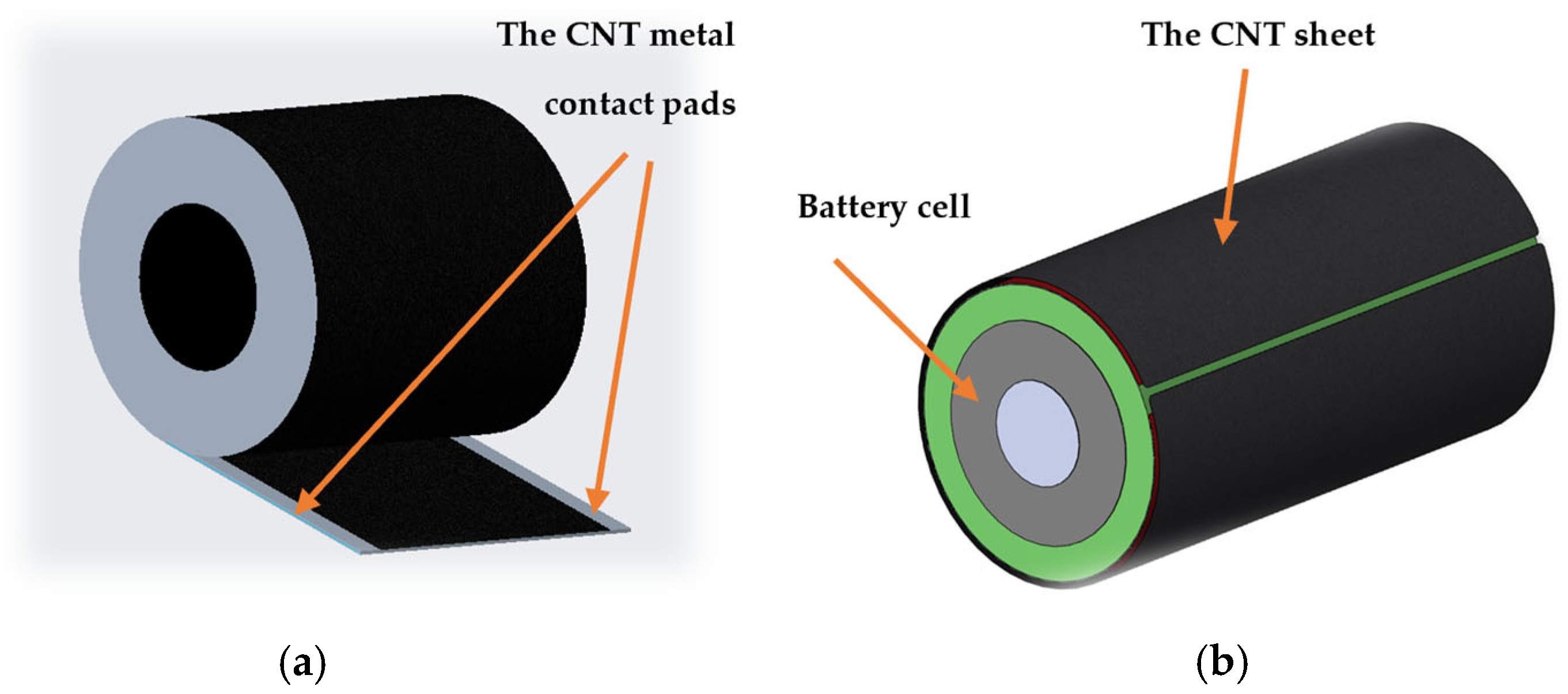
2.1. Design of the CNT Sheet-Based Heating Scheme

In this study, a lithium-ion cell integrated with a CNT sheet-based heating layer was evaluated using an in-house-developed datalogger and relay control board. This setup was designed as part of a broader initiative to develop a smart battery pack solution for forklift operations in subzero temperature environments. A commercial lithium iron phosphate (LFP) 26650 cell was selected for the experiments, with a nominal capacity of 2.5 Ah and a rated voltage of 3.3 V. The detailed specifications of the cell are provided in Table 2.
The CNT sheet used for this experiment is a flexible, sheet-type material that can be bent, rolled, and easily conformed to various shapes, making it suitable for integration into deformable or wearable electronic systems. This CNT sheet exhibits excellent electrical and thermal conductivity, low mass density, and high mechanical strength. Its typical features are summarized in Table 3. Owing to its thin and pliable structure, the sheet can be readily folded and trimmed to match the dimensions of the LFP 26650 cell, forming a compact LFP–CNT Assembly, as illustrated in Figure 1. When tightly wrapped around the cell, the CNT sheet maintains close and uniform contact with the surface, ensuring efficient heat transfer. This one-dimensional heating configuration enables uniform and localized thermal regulation along the length of the battery, supporting its stable operation under subzero conditions.
Leveraging these features, the integration of CNT sheets into battery packs allows for rapid and efficient preheating in subzero conditions. This helps to minimize energy loss and supports more reliable battery performance during cold startups.

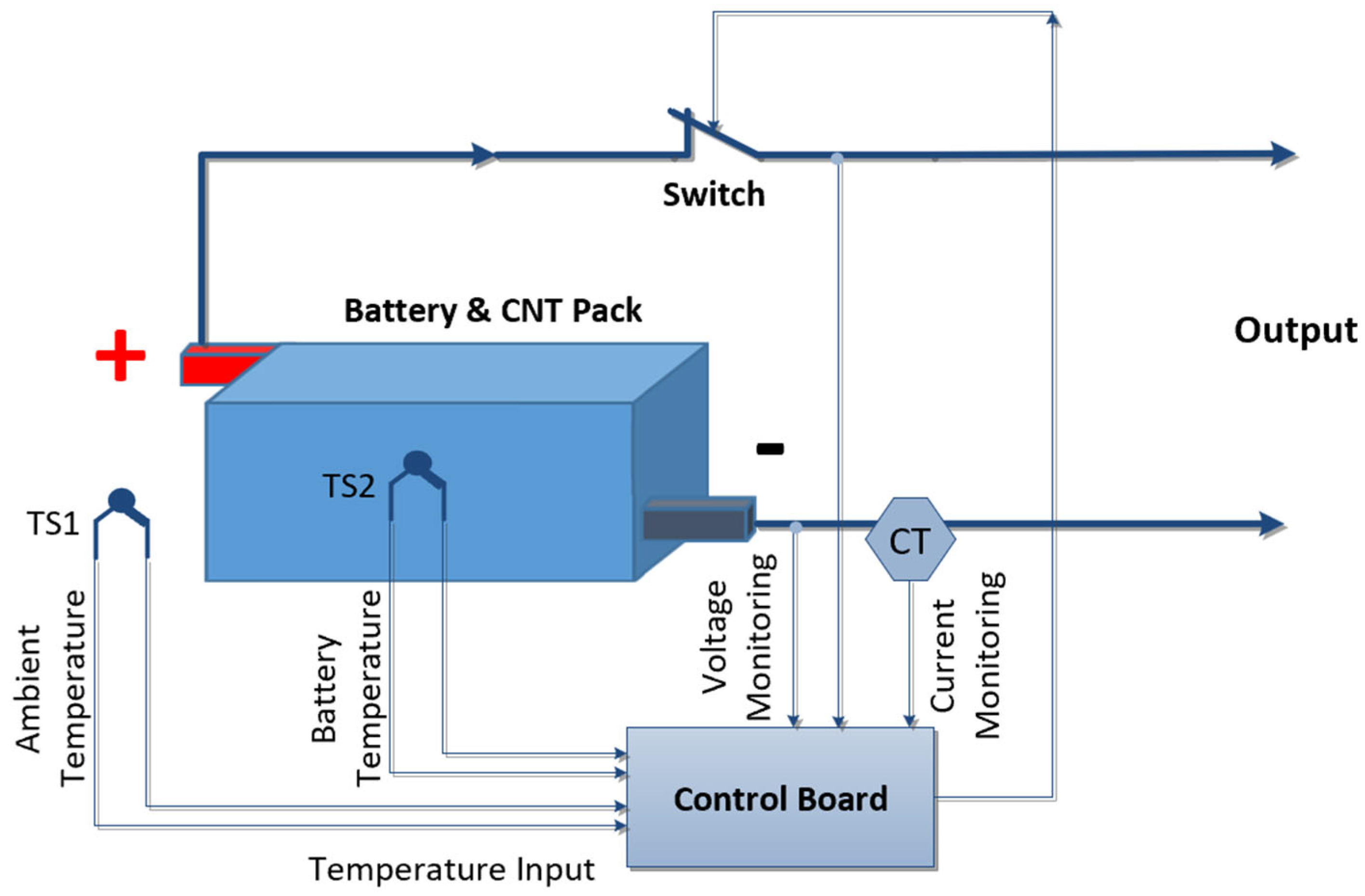
2.2. The Design and Fabrication of the CNT Heat-Up System

The CNT-based heating system consists of the following main components: the LFP–CNT Assembly (comprising a lithium iron phosphate battery cell and CNT sheet), a control board, and temperature sensors. The control board, developed in-house, is based on an embedded system architecture that integrates sensor interfaces, relays, a control panel, and Wi-Fi connectivity into a compact and lightweight module. This streamlined design facilitates easy integration into the test setup while minimizing spatial and weight constraints. The control board continuously monitors the temperatures of the battery cell, the CNT heating layer, and the surrounding environment within the temperature chamber. Owing to its thin, flexible, and customizable form, the CNT sheet can be readily cut to size, arranged in series or parallel configurations, and wrapped tightly around the battery cell. This configuration enables direct and efficient thermal conduction from the CNT sheet to the battery surface. The relay control board regulates the on/off operation of the CNT heating sheet, ensuring temperature control to maintain the battery within the desired operating range. The complete system layout is depicted in Figure 2. At its core, the LFP–CNT Assembly is housed within a custom-designed insulated enclosure that minimizes heat loss and ensures the efficient retention of the generated thermal energy. Temperature sensors are strategically placed to monitor critical points in the system. Specifically, sensors TS1 (ambient temperature) and TS2 (battery temperature) are positioned to track the ambient conditions inside the chamber and the battery cell temperature. For experimental testing, the entire battery pack and enclosure are placed within a temperature chamber to simulate various subzero conditions. The datalogger records temperature readings from the sensors. It also executes closed-loop temperature control: When the cell temperature drops below a predefined lower threshold, the CNT heater will be turned on. Heating continues until the upper threshold is reached; the CNT heater will be turned off.
Additionally, the system includes onboard data storage via a local memory card embedded in the control board, allowing all thermal data to be logged for post-experiment analysis.

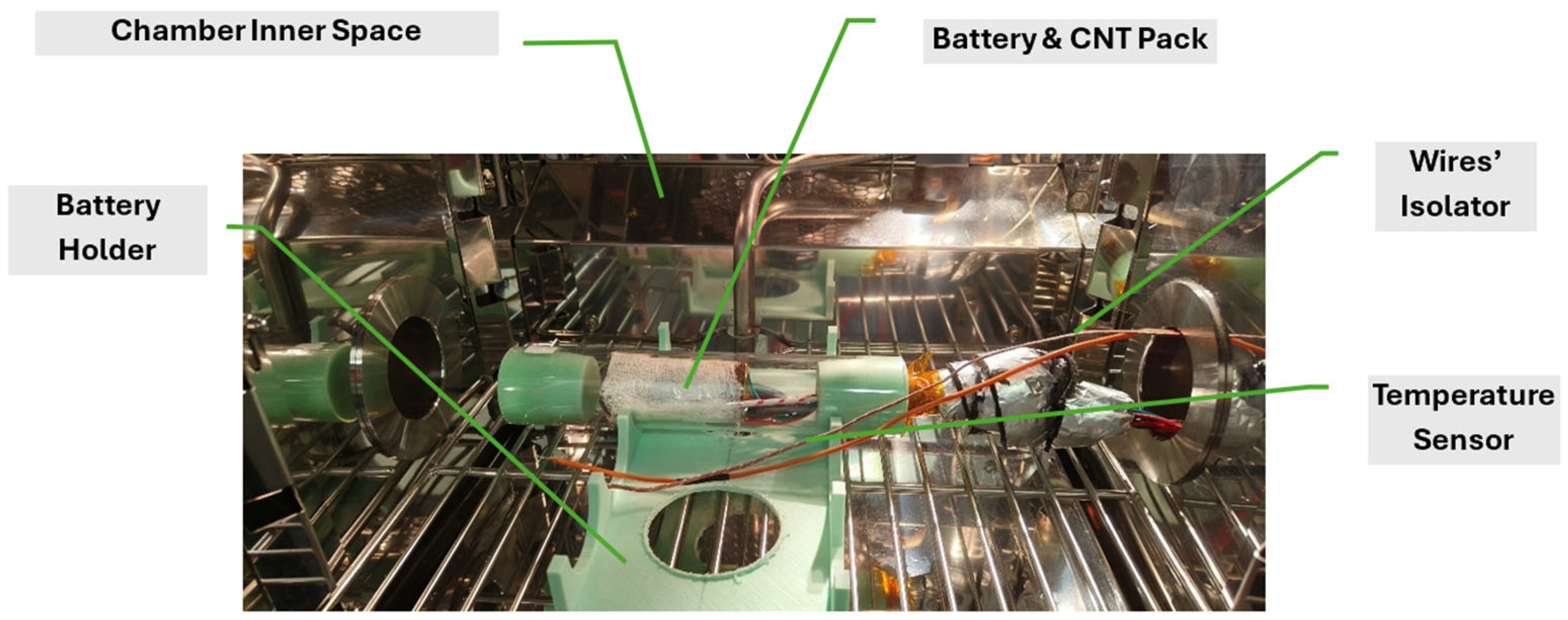
2.3. Testing Setup and Procedure of the CNT Heat-Up System

In this experiment, a Chroma Regenerative Battery Pack Test System 17020 was employed to perform controlled discharge processes, while a WEISS WKL 34/40 temperature chamber provided a stable and precisely regulated thermal environment. For this study, two specific low-temperature conditions were selected: −20 °C and −30 °C.
The LFP battery cell, wrapped with the CNT sheet, was enclosed in a sealed acrylic tube fitted with rubber stoppers at both ends to minimize thermal losses. This Assembly was securely mounted in a fixed holder within the temperature chamber, as illustrated in Figure 3.
During the experiment, the CNT heating layer was automatically on/off based on real-time cell temperature readings. A heating cycle was triggered when the battery temperature fell below −1 °C, at which point the CNT heater was turned on. Heating continued until the cell temperature reached 2 °C, whereupon the heater was turned off. This closed-loop control maintained the cell temperature within a narrow and controlled window, ensuring thermal stability and consistent performance during discharge under subzero conditions.

3. Results and Discussion

3.1. Discharge Under 25 °C Without CNT

To support the experiment involving the A123 26650 Li-ion battery cell under extremely low temperatures, a benchmark discharge test was first conducted at 25 °C. This provided a standardized baseline for subsequent analysis and comparison. The test results are summarized in Table 4.

3.2. Discharge Under −20 °C Without CNT Heating

The temperature chamber and battery cell required about 6000 s to stabilize at the same temperature. Once stabilized, a discharge test was initiated at a 1 C rate using a constant current of 2.5 A. The cutoff voltage was set to 2.7 V, and the discharge process lasted approximately 2200 s, at which point the cell voltage dropped to the cutoff threshold.
A notable observation during this period was the self-heating effect of the battery. Despite the ambient temperature of −20 °C, the cell temperature increased from −19.5 °C to −9.4 °C—an increase of 10.1 °C—due to the cell’s internal heat generation caused by the 2.5 A discharge current. This phenomenon highlighted the role of internal resistance in generating heat during high-current discharge in low-temperature environments.
As a result, the discharged capacity was measured at 1.585 Ah (compared to 2.50 Ah at 25 °C), representing 63.4% of the cell’s nominal capacity. The energy released was 4.60 Wh (versus 8.00 Wh at 25 °C), which corresponded to 57.5% of the battery’s rated energy. The battery voltage and temperature profiles during the −20 °C discharge without CNT are illustrated in Figure 4.

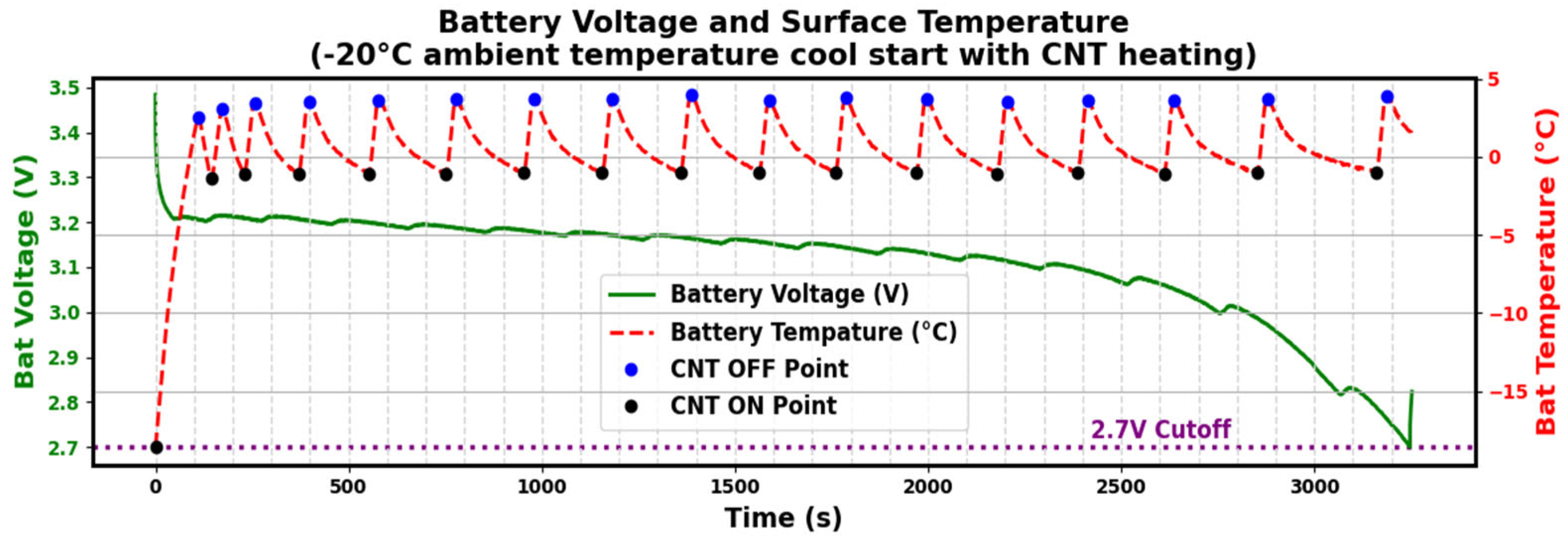
3.3. Discharge Under −20 °C with CNT Heating

Following the same procedure outlined in Section 3.2, the initial ambient temperature was approximately 20 °C. The battery and CNT sheet pack—sealed inside an acrylic tube—took about 6000 s to reach −20 °C.
After the battery had stabilized at −20 °C for a short period, the CNT sheet heating was turned on to preheat the battery. Once the battery temperature reached 0 °C, the discharge process commenced. When the battery temperature reached 2 °C, the CNT was turned off; if the battery temperature dropped down to −1 °C, the CNT would be turned on.
Subsequently, the CNT sheet operated in an intermittent on/off mode to maintain the battery temperature within the range of −1 °C to 2 °C, effectively stabilizing it around 0 °C. It was recorded that the battery temperature rose from −20 °C to 0 °C in 97 s. The CNT sheet was turned on–off 17 times during the discharge period to maintain the battery temperature at 0 °C, with each heating lasting approximately 16 s, and the off period was 123 s; thus, the duty cycle for the CNT heating was 11.51%. Figure 5 demonstrates the battery voltage and battery temperature when it was discharged under −20 °C with CNT heating.
The discharge process lasted for 3329 s, 296 s less than the benchmark test, which was 3625 s at 25 °C. The measured discharged capacity was 2.25 Ah (compared to 2.50 Ah at 25 °C), corresponding to 90% of the rated capacity. The energy output was 7.09 Wh (compared to 8.00 Wh at 25 °C), excluding CNT power consumption, representing 88.6% of the battery’s nominal energy. The detailed waveform of the CNT on/off modes is shown in Figure 6.
By further analyzing the recorded battery temperature data, the CNT heating cycle index over time was extracted and is presented in Figure 7. In this figure, the red bars represent the CNT heating on duration, while the blue bars indicate the off duration. The X-axis shows the cycle index, and the Y-axis represents the duration between successive CNT heating events.
During the initial phase of the experiment, the on/off durations were relatively short—typically between 50 and 150 s—indicating a high frequency of heating cycles as the system worked to stabilize the battery temperature within the target range. As the experiment progressed, the durations showed an upward trend, gradually extending to around 300 s. This suggested the system was approaching thermal equilibrium, with reduced temperature fluctuations requiring less frequent heating.
As discussed in Section 3.2, battery self-heating during discharge contributed to this stabilization. The decreasing reliance on CNT heating over time highlighted a hybrid approach: using the CNT sheet for initial heating, followed by using the battery’s self-heating to maintain the desired temperature range more efficiently. This trend reflected improved thermal consistency and system efficiency, underscoring the potential of CNT-based heating solutions for reliable battery operation in cold environments.

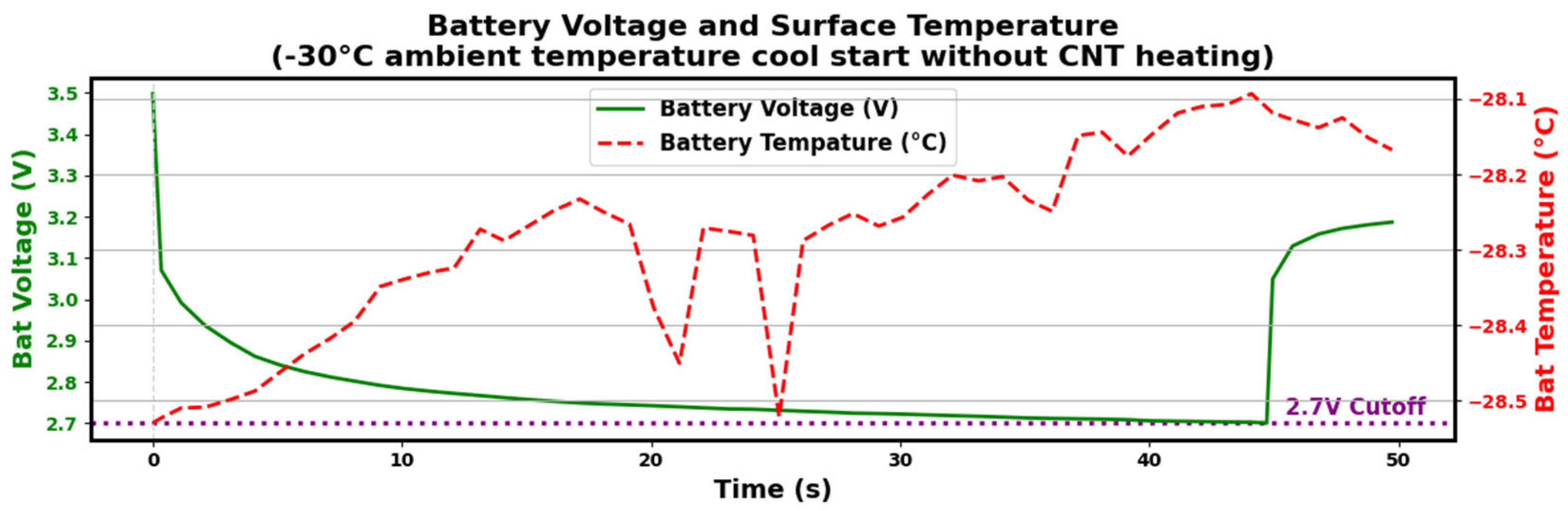
3.4. Discharge Under −30 °C Without CNT Heating

The battery’s performance was significantly degraded during discharge at −30 °C. When the cell temperature reached −30 °C, the discharge process commenced with a current of 2.5 A. However, as depicted in Figure 8, the discharge lasted for only 45 s. Due to this extremely short duration, the output power and capacity were negligible, even with the discharge rate set at 1 C. Additionally, there was no noticeable change in the cell’s temperature throughout the discharge process, which meant the battery’s self-heating was not performed effectively, further highlighting the battery’s poor performance under such an extremely cold environment.

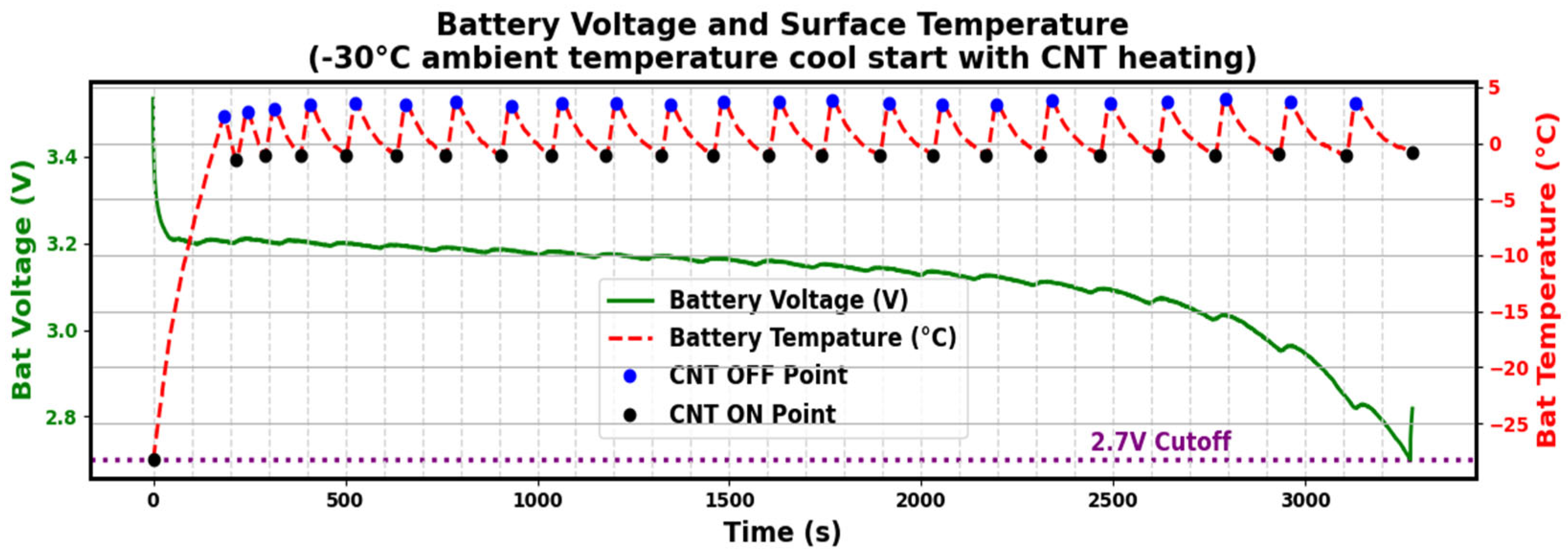
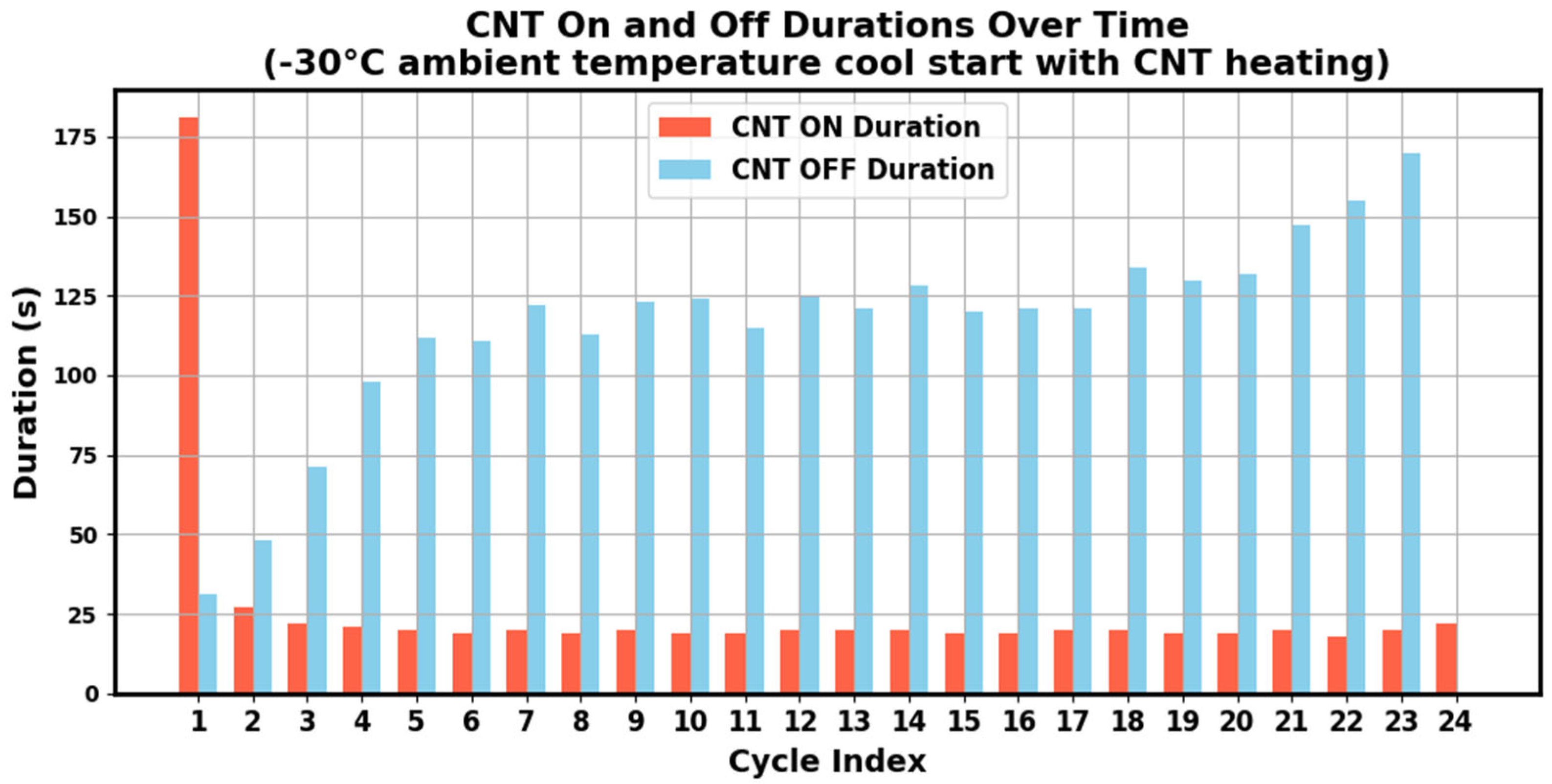
3.5. Discharge Under −30 °C with CNT Heating

The discharge process of the battery and CNT-integrated pack began at an initial temperature of 20 °C, with the temperature chamber set to −30 °C. Once the cell temperature stabilized at the target low temperature, the CNT heating system was turned on, and the cell temperature was continuously monitored. The recorded data showed that it took 141 s for the battery cell to heat from −30 °C to 0 °C. As shown in Figure 9, during the discharge period, the CNT sheet cycled 23 times to stabilize the temperature, with each heating lasting approximately 18 to 21 s. For this discharge process, the current was maintained at 2.5 A, with a cutoff voltage of 2.7 V. The discharge lasted 3494 s, less than the benchmark test, which was 3625 s at 25 °C, delivering a capacity of 2.25 Ah, the same as the value under −20 °C, which represented 90% of the battery’s total capacity. The energy released during the discharging period was 5.84 Wh, excluding CNT power consumption, accounting for 73% of the battery’s total energy, 15.63% less than under −20 °C because of energy consumption. This demonstrated the effectiveness of the CNT sheet in maintaining optimal operating conditions, even in an extremely cold environment. The CNT heating cycle index over time can be seen in Figure 10.
Based on the experimental findings from this study, the experimental results are summarized in Table 5.

4. Conclusions

This study demonstrated the integration of a new CNT sheet-based heating layer in a Li-ion battery pack to enhance the performance of Li-ion cells in subzero environments. By addressing the key challenges such as startup failures and the reduced capacity and poor performance in the extreme cold, particularly at temperatures as low as −30 °C, the system utilized the lightweight, flexible, and energy-efficient properties of CNT sheets to maintain optimal battery temperature, preventing the degradation and capacity loss of the battery cell. The experiments showed that CNT, with a high thermal conductivity, large specific surface area, and low specific gravity, offered distinct advantages when fabricated into a sheet. Importantly, CNT sheets can be fabricated outside of the battery, eliminating the need for design modifications. This feature enables compatibility with different types and sizes of battery cells, such as cylindric, prismatic, and pouch as well, offering high effectiveness at a low cost. The experimental results showed severe performance issues without CNT heating. At −20 °C, the battery discharged only 63.4% of its capacity, producing 57.5% of its total energy, with minimal self-heating. At −30 °C, discharge lasted just 45 s with a negligible capacity or energy output. By contrast, with CNT heating, the performance improved significantly. At −20 °C, the CNT sheet raised the battery temperature to 0 °C in 97 s, enabling 90% of the capacity and 88.63% of the energy output. At −30 °C, the battery reached 0 °C in 141 s, achieving 90% of the capacity and 73% of the energy output. The CNT sheet provided efficient thermal conductivity and rapid and uniform heating while minimizing heat loss, enabling an extended battery life and enhanced operational reliability in subzero environments. Integrated with a battery pack, the system used an IoT-based solution that included temperature sensors and on/off control to the CNT sheet based on real-time feedback. The IoT capability also enabled remote monitoring and supported advanced control algorithms. The added weight and size were minimal—less than 1% of the battery—making the system highly compact and efficient. At the pack level, efficiency can be further improved, as the inner cells may require less heating than the outer ones. System-level design and optimization will be explored in the next phase of development. This approach shows promise for different battery sizes and chemistries, though additional work is needed to broaden the applicability. Its scalability and affordability position it as a transformative innovation for industrial applications in extremely cold environments, but its long-term performance and cost-effectiveness still require validation. Overall, the design marks a step towards improving cold-condition battery performance and will be refined for industrial deployment.

Author Contributions

Conceptualization, J.J. and M.H.; methodology, J.J., M.H. and G.W.; software, Z.G.; validation, J.J. and M.H.; formal analysis M.H., J.J., and G.W.; investigation, G.W. and Z.G.; writing—original draft, J.J.; writing—review and editing, J.J., M.H., G.W. and Z.G.; figures, G.W. and J.J.; project administration, J.J. and G.W. All authors have read and agreed to the published version of the manuscript.

Funding

This research was funded by Ministry of Education (MOE), Singapore grant number MOE2022_TIF-0015.

Institutional Review Board Statement

Not applicable.

Informed Consent Statement

Not applicable.

Data Availability Statement

The original data of the study is included in the article; further inquiries can be directed to the corresponding author.

Acknowledgments

This research project is supported by the Ministry of Education, Singapore, under its MOE TIF Grant Call of the funding programme.

Conflicts of Interest

The authors declare no conflicts of interest.

Abbreviations

The following abbreviations are used in this manuscript:
CNTCarbon Nanotube
PCMsPhase Change Materials
SOCState of Charge
LFPLithium Iron Phosphate
TSTemperature Sensor
CTCurrent Transformer
CCConstant Current

References

  1. Somasundaram, S.; Chiam, S.Y.; Lin, M.C. Energy Storage Systems Technology Roadmap for Singapore; Nanyang Technological University: Singapore, 2020. [Google Scholar]
  2. Peng, X.; Chen, S.; Garg, A.; Bao, N.; Panda, B. A review of the estimation and heating methods for lithium-ion batteries pack at the cold environment. Energy Sci. Eng. 2019, 7, 645–662. [Google Scholar] [CrossRef]
  3. Wang, C.Y.; Zhang, G.; Ge, S.; Xu, T.; Ji, Y.; Yang, X.G.; Leng, Y. Lithium-ion battery structure that self-heats at low temperatures. Nature 2016, 529, 515–518. [Google Scholar] [CrossRef] [PubMed]
  4. Qu, Z.; Jiang, Z.; Wang, Q. Experimental study on pulse self-heating of lithium-ion battery at low temperature. Int. J. Heat Mass Transf. 2019, 135, 696–705. [Google Scholar] [CrossRef]
  5. Zhang, J.; Ge, H.; Li, Z.; Ding, Z. Internal heating of lithium-ion batteries using alternating current based on the heat generation model in frequency domain. J. Power Sources 2015, 273, 1030–1037. [Google Scholar] [CrossRef]
  6. Hu, X.; Zheng, Y.; Howey, D.A.; Perez, H.; Foley, A.; Pecht, M. Battery warm-up methodologies at subzero temperatures for automotive applications: Recent advances and perspectives. Prog. Energy Combust. Sci. 2020, 77, 100806. [Google Scholar] [CrossRef]
  7. DuBeshter, T.; Jorne, J. Pulse Polarization for Li-Ion Battery under Constant State of Charge: Part I. Pulse Discharge Experiments. J. Electrochem. Soc. 2017, 164, E3539. [Google Scholar] [CrossRef]
  8. Ji, Y.; Wang, C.Y. Heating Strategies for Li-Ion Batteries Operated from Subzero Temperatures; The Electrochemical Society: Pennington, NJ, USA, 2012. [Google Scholar]
  9. Jaguemont, J.; Boulon, L.; Dubé, Y. A comprehensive review of lithium-ion batteries used in hybrid and electric vehicles at cold temperatures. Appl. Energy 2016, 164, 99–114. [Google Scholar] [CrossRef]
  10. Lei, Z.; Zhang, Y.; Lei, X. Temperature uniformity of a heated lithium-ion battery cell in cold climate. Appl. Therm. Eng. 2018, 129, 148–154. [Google Scholar] [CrossRef]
  11. Li, W.; Qu, Z.; He, Y.; Tao, Y. Experimental study of a passive thermal management system for high-powered lithium ion batteries using porous metal foam saturated with phase change materials. J. Power Sources 2014, 255, 9–15. [Google Scholar] [CrossRef]
  12. Yang, X.-G.; Liu, T.; Wang, C.-Y. Innovative heating of large-size automotive Li-ion cells. J. Power Sources 2017, 342, 598–604. [Google Scholar] [CrossRef]
  13. Review of the North American Lithium Forklift Battery Market: The 7 Most Popular Brands in the USA and Canada. Available online: https://www.onecharge.biz/blog/review-of-the-north-american-lithium-forklift-battery-market-the-7-most-popular-brands-in-the-usa-and-canada/ (accessed on 20 March 2022).
  14. Yan, J.; Wang, C.Y. Heating strategies for Li-ion batteries operated from subzero temperatures. Electrochim. Acta 2013, 107, 664–674. [Google Scholar]
  15. Xu, F.; Aouraghe, M.A.; Xie, X.; Zheng, L.; Zhang, K.; Fu, K.K. Highly stretchable, fast thermal response carbon nanotube composite heater. Compos. Part A Appl. Sci. Manuf. 2021, 147, 106471. [Google Scholar] [CrossRef]
  16. Chiew, J.; Chin, C.; Toh, W.; Gao, Z.; Jia, J. Thermal state-of-expansion or melting of phase change material based heat sink for underwater battery power system. J. Energy Storage 2019, 26, 100956. [Google Scholar] [CrossRef]
  17. Gao, Z.; Chin, C.S.; Chiew, J.H.K.; Jia, J.; Zhang, C. Design and Implementation of a Smart Lithium-Ion Battery System with Real-Time Fault Diagnosis Capability for Electric Vehicles. Energies 2017, 10, 1503. [Google Scholar] [CrossRef]
  18. Chiew, J.; Chin, C.; Toh, W.; Gao, Z.; Jia, J.; Zhang, C. A pseudo three-dimensional electrochemical-thermal model of a cylindrical LiFePO4/graphite battery. Appl. Therm. Eng. 2019, 147, 450–463. [Google Scholar] [CrossRef]
  19. DyNano-Pyroabnd Specification. Available online: www.douyee.com.sg (accessed on 20 March 2022).
  20. Pop, E.; Varshney, V.; Roy, A.K. Thermal properties of graphene and carbon nanotubes. Nano Res. 2012, 5, 239–260. [Google Scholar]
  21. Berber, S.; Kwon, Y.-K.; Tomanek, D. Unusually high thermal conductivity of carbon nanotubes. Phys. Rev. Lett. 2000, 84, 4613. [Google Scholar] [CrossRef] [PubMed]
  22. Kumanek, B.; Janas, D. Thermal conductivity of carbon nanotube networks: A review. J. Mater. Sci. 2019, 54, 7397–7427. [Google Scholar] [CrossRef]
Figure 1. The fabrication of the Li-ion cell and CNT sheet: (a) the CNT sheet; (b) the LFP-CNT Assembly.
Energies 18 02958 g001
Figure 2. The design of the CNT-based battery heating and control system.
Energies 18 02958 g002
Figure 3. The inner view of the temperature chamber with the battery pack.
Energies 18 02958 g003
Figure 4. The battery voltage and temperature when it was discharged under −20 °C without CNT heating.
Energies 18 02958 g004
Figure 5. The battery voltage and battery temperature when it was discharged under −20 °C with CNT heating.
Energies 18 02958 g005
Figure 6. The waveform of the CNT on/off current under −20 °C.
Energies 18 02958 g006
Figure 7. CNT heating cycle index over time under −20 °C.
Energies 18 02958 g007
Figure 8. The temperature curves of the chamber and battery when the battery was discharged under −30 °C without CNT heating.
Energies 18 02958 g008
Figure 9. The temperature curves of the CNT sheet and battery when the battery was discharged under −30 °C with CNT heating.
Energies 18 02958 g009
Figure 10. CNT heating cycle index over time under −30 °C.
Energies 18 02958 g010
Table 1. Comparison and summary of the thermal management systems.
ClassificationSub-ClassAdvantagesDisadvantages
Passive method PCM-based thermal managementIt does not consume energy to heat battery packs. PCMs store and release heat when it melts or freezes at the given condition.
  • The contribution to keeping the temperature stable is not significant.
  • Its weight and volume are not neglectable.
Active methodInternal heatingSelf-internal heatingIt does not require an additional heat transfer system or circuit components, which enables its low cost and high reliability. Most research is performed in this area.
  • It suffers from low heating efficiency and thus extra battery capacity loss.
  • It requires a longer duration compared to the other strategies.
AC heatingOne of the most efficient preheating approaches, which can heat the battery quickly and uniformly.The cell resistance inconsistency gives rise to different heat generation rates inside each cell and thus causes a temperature gradient inside the battery module/pack.
Mutual pulse heating
  • High reliability;
  • Low maintenance;
  • High energy efficiency;
  • High heating rate.
Requires specially designed circuits and control systems, which significantly increase the cost when the battery is at a high SOC level, considering the effect of lithium plating.
A nickel foil is embedded inside a cellThe existing internal heating methods can heat the battery in a fast way.
  • The conversion percentage of electrical energy into heat is not high enough.
  • The structures are too complicated.
Convective heatingInternal convective heatingThermal field is more even.Requires a closed system, including flow channels, heaters, fans, and batteries, while ensuring minimal heat loss.
External convective heating
  • Thermal field is more even;
  • Energy efficiency is high.
Table 2. The battery properties.
Battery TypeLFP
Cell Dimensionsφ26 × 65 mm
Cell Weight76 g
Cell Capacity (nominal/minimum)2.50/2.40 Ah
Voltage (nominal)3.3 V
Internal Impedance (1 kHz AC typical)6 mΩ
Cycle Life at 20 A Discharge, 100% DOD>1000 cycles
Table 3. The typical features of the CNT sheet.
CNT SheetTypical Features
Thickness20 µm
Resistance110 Ω
Thermal conductivity>2000 W/mK
Dimensions200 (Length) × 65 (Width) mm
Table 4. A123 Li-ion cell discharge test under 25 °C.
Key ItemsParameters
Chamber Temperature25 °C
Discharge ModeConstant Current (CC)
Discharge Current1 C at 2.50 A
Capacity Output2.50 Ah
Energy Output8.00 Wh
Cutoff Voltage2.70 V
Duration of the Discharge3625 s
Table 5. The summary of the experimental results.
Operation ConditionStartup Time
(s)
Capacity Output
(Ah)
Energy Output
(Wh)
25 °C-2.508.00
−20 °C without CNT heating-1.585, (63.4%)4.60, (57.5%)
−20 °C with CNT heating972.25, (90%)7.09, (88.6%)
−30 °C without CNT heating-0.03, (1.2%)0.082, (1.02%)
−30 °C with CNT heating1412.25, (90%)5.84, (73.0%)
Disclaimer/Publisher’s Note: The statements, opinions and data contained in all publications are solely those of the individual author(s) and contributor(s) and not of MDPI and/or the editor(s). MDPI and/or the editor(s) disclaim responsibility for any injury to people or property resulting from any ideas, methods, instructions or products referred to in the content.

