Article

Effect of Improved Combustion Chamber Design and Biodiesel Blending on the Performance and Emissions of a Diesel Engine

1
College of Machinery and Transportation, Southwest Forestry University, Kunming 650224, China
2
Key Laboratory of Environmental Protection and Safety for Motor Vehicles in Plateau and Mountainous Regions of Yunnan Province, Kunming 650224, China
3
College of Machinery and Transportation, Dehong Vocational College, Mangshi 678400, China
*
Author to whom correspondence should be addressed.
Energies 2025, 18(11), 2956; https://doi.org/10.3390/en18112956
Submission received: 25 April 2025 / Revised: 26 May 2025 / Accepted: 30 May 2025 / Published: 4 June 2025
(This article belongs to the Section I2: Energy and Combustion Science)

Abstract

This study aims to investigate the impact of combustion chamber geometry and biodiesel on the performance of diesel engines under various load conditions. Simulations were conducted using AVL FIRE software, followed by experimental validation to compare the performance of the prototype Omega combustion chamber with the optimized TCD combustion chamber (T for turbocharger, C for charger air cooling, and D for diesel particle filter). This study utilized four types of fuels: D100, B10, B20, and B50, and was conducted under different load conditions at a rated speed of 1800 revolutions per minute (rpm). The results demonstrate that the TCD combustion chamber outperforms the Omega chamber in terms of indicated thermal efficiency (ITE), in-cylinder pressure, and temperature, and also exhibits a lower indicated specific fuel consumption (ISFC). Additionally, the TCD chamber shows lower soot and carbon monoxide (CO) emissions compared to the Omega chamber, with further reductions as the load increases and the biodiesel blend ratio is raised. The high oxygen content in biodiesel helps to reduce soot and CO formation, while its lower sulfur content and heating value contribute to a decrease in combustion temperature and a reduction in nitrogen oxide (NOx) production. However, the NOx emissions from the TCD chamber are still higher than those from the Omega chamber, possibly due to the increased in-cylinder temperature resulting from its combustion chamber structure. The findings provide valuable insights into diesel engine system design and the application of oxygenated fuels, promoting the development of clean combustion technologies.

1. Introduction

With the advancement of science and technology and the enhancement of living standards, China has become one of the world’s major modern automobile production and sales powers [1,2]. Due to the surge in greenhouse gas emissions, climate change, and the depletion of energy resources [3], countries have introduced increasingly stringent emission regulations. In 2020, China set forth two critical goals: achieving carbon peak by 2030 and carbon neutrality by 2060 [4]. In response to these government mandates, the Ministry of Environmental Protection of China has promulgated stricter vehicle exhaust emission standards to mitigate environmental pollution caused by motor vehicle emissions [5]. The rapid development of new energy technologies [6] and the vigorous promotion of power battery technology [7] are driving the automotive industry towards an energy-saving and environmentally friendly transformation. These factors present unprecedented challenges for diesel engines. However, due to their high reliability and efficiency, diesel engines are expected to continue serving as power sources in the foreseeable future in areas such as heavy-duty vehicles, special military vehicles, power generation units, and agricultural machinery [8,9,10].
Currently, to facilitate the transition of diesel engines towards energy conservation and environmental protection, the utilization of oxygenated fuels [11,12,13] and the optimization of combustion chamber design have emerged as crucial technical approaches to enhance the thermal efficiency of diesel engines and diminish pollutant emissions [14,15,16]. Both domestically and internationally, there is a substantial amount of research on the utilization of oxygenated fuels [17,18,19] and the optimization of combustion chamber geometry [20,21,22,23]. Biodiesel has garnered considerable attention from researchers due to its properties that are comparable to or even superior to those of conventional fossil diesel [24,25,26]. Kalam et al. [27] conducted a performance study on biodiesel derived from waste cooking oil. Their findings revealed that in comparison to conventional diesel, blends of waste cooking oil biodiesel led to a decrease in power output. However, they also resulted in a significant reduction in the emissions of harmful pollutants such as CO, HC, and particulate matter. The study suggests that despite a slight decline in engine performance, the environmental advantages in terms of emission reduction are considerable. Tamrat et al. [28] investigated the combustion and emission characteristics of castor oil biodiesel at various blend ratios (B0, B5, B10) with the addition of 2% dimethyl ether (DME) in a water-cooled four-stroke diesel engine. The study found that increasing the blend ratio of castor oil biodiesel resulted in higher cylinder pressure and heat release rates but also led to increased nitrogen oxide emissions. Furthermore, the addition of DME was found to reduce carbon monoxide emissions; however, it necessitates operation at high engine speeds. The authors recommend using castor oil biodiesel in combination with DME additives to optimize the emission performance of diesel engines. Ramesh Babu et al. [29] investigated the effects of using zinc oxide (ZnO) as a fuel additive in diesel engines when utilizing cottonseed biodiesel. When this additive was mixed with 25% biodiesel, it significantly improved engine performance compared to neat diesel, including an increase in brake thermal efficiency (BTE), enhancement in energy release rate, and reduction in the emissions of hydrocarbons (HC) and carbon monoxide (CO) in the exhaust gases. Furthermore, due to the oxygen content in biodiesel, the emissions of nitrogen oxide (NOx) were also reduced, reaching a level of 125 PPM [30]. Udayakumar P et al. [31] further explored the impact of different injection pressures on the performance of cottonseed oil biodiesel in diesel engines. Additionally, variations in the combustion chamber geometry affect the mixing of the in-cylinder charge, and the quality of the mixture has a significant influence on the in-cylinder combustion process, thereby leading to changes in power, economy, and emission performance [32,33]. Jyoti and Reddy [34] conducted a comparative study on three different combustion chamber designs for compression-ignition engines, including the Toroidal Re-entrant Combustion Chamber (TRCC), the Hemispherical Combustion Chamber (HCC), and the Toroidal Combustion Chamber (TCC). The study found that the thermal efficiency of the TRCC and TCC was enhanced by 3.28% and 2.94%, respectively, compared to the HCC. However, due to the air swirl effect within the cylinder, the maximum energy release for the TRCC and TCC was reduced by 3.1% and 1.3%, respectively. Yaliwal et al. [35] evaluated the performance of five distinct piston geometries in a diesel engine, namely the hemispherical piston bowl (HPB), the re-entrant piston bowl (RPB), the lateral swirl piston bowl (LSPB), the dual swirl piston bowl (DSPB), and the lateral and dual swirl piston bowl (LDSPB). Comparatively, the LDSPB geometry demonstrated a 10.6% increase in thermal efficiency and a reduction in carbon emissions by approximately 5–26%. However, there was a 25.4% increase in NOx emissions. Li et al. [36,37] designed two combustion systems: the forced swirl combustion system (FSCS) and the multi-swirl combustion system (MSCS). These systems generate longitudinal or transverse swirls through the impingement of the nozzle on the wall, thereby expanding the diffusion space of the fuel, accelerating the mixing of fuel with air, and subsequently improving the combustion process.
To investigate the effects of combustion chamber geometry and biodiesel on engine performance, this study focused on a specific type of diesel engine. Utilizing AVL FIRE software, the original Omega combustion chamber and the TCD (turbocharger, charge air cooling, diesel particle filter) combustion chamber, the latter of which being optimized, were modeled while maintaining a consistent compression ratio. The fuels used included D100 (pure diesel), B10 (10% biodiesel, 90% diesel), B20 (20% biodiesel, 80% diesel), and B50 (50% biodiesel, 50% diesel). Calculations were conducted for the two combustion chambers under loads of 25%, 50%, 75%, and 100%, with the results validated through tests at an altitude of 2000 m on a plateau. Most of the studies in the existing literature focus on combustion and emission characteristics under plain conditions, or do not specifically investigate the blending of diesel and biodiesel in plateau environments. This study integrates plateau conditions, biodiesel blending, and three-dimensional simulation techniques to not only analyze fundamental parameters such as in-cylinder pressure and temperature but also comprehensively examine indicators such as indicated thermal efficiency, indicated specific fuel consumption, and NOx and soot emissions. The findings of this study can provide valuable data support for the optimized design of diesel engine combustion systems in plateau regions and offer important insights into the combustion characteristics of oxygenated fuels under high-altitude conditions. This will help guide the development of combustion systems for diesel engines operating in plateau environments, optimize the combustion process, reduce NOx and soot emissions, and provide a scientific basis for achieving energy conservation and emission reduction goals.

2. Materials and Methods

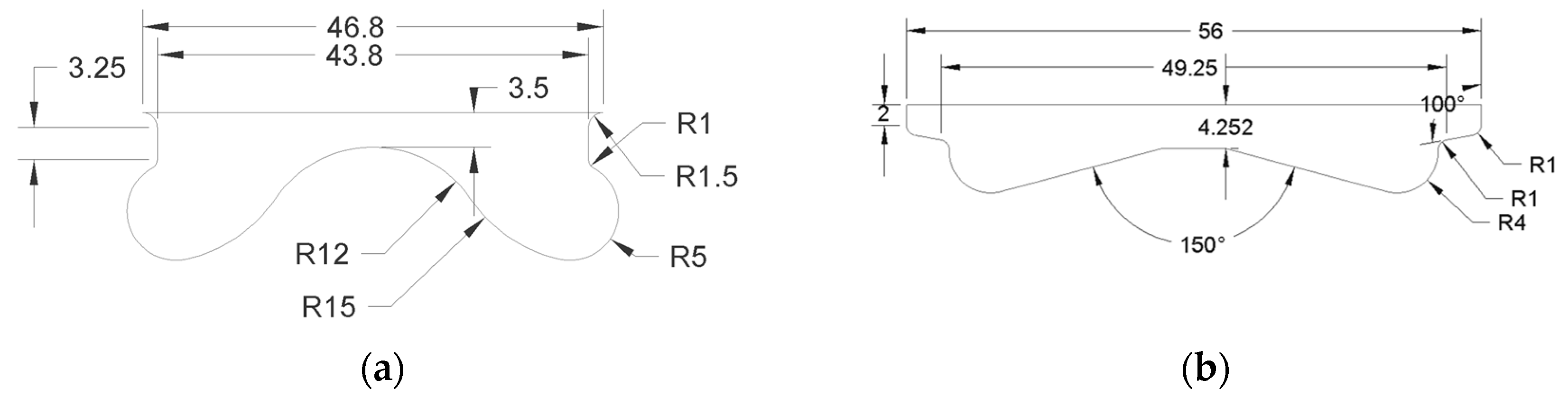
2.1. Simulation Model Parameter Settings

The engine utilized in this study is a four-cylinder, four-stroke diesel engine, with the main engine parameters listed in Table 1. The combustion chamber is of the deep pit Omega type. The experimental location is Kunming, Yunnan, at an altitude of 2000 m, and the test condition is at a full load with a speed of 1800 revolutions per minute (r/min). The simulation model parameters are set according to the experimental control parameters. Table 2 presents the initial conditions and simulation boundary conditions. Table 3 outlines the selection of each sub-model.

2.2. Test Oils

Biodiesel (with soybean oil as the raw material) was blended with conventional diesel in specific volume ratios to prepare four fuel types: B10 (10% v/v biodiesel and 90% v/v diesel), B20 (20% v/v biodiesel and 80% v/v diesel), B50 (50% v/v biodiesel and 50% v/v diesel), and pure diesel D100 (100% v/v diesel). The physical and chemical properties of both diesel and biodiesel were tested by the Oil Product Analysis Institute of Sinopec Group. The main experimental equipment included the DSY-006B tester for pour point, solidification point, cloud point, and cold filter plugging point; the BSH-2 closed cup flash point tester; a constant temperature bath for kinematic viscosity measurements; the DSY-020 copper strip corrosion tester; the DSS-1 moisture content analyzer; and the DRD-100 automatic distillation apparatus. The main physical and chemical properties of these fuel blends are summarized in Table 4.

2.3. Simulation Model and Methodology

The established combustion chamber model was simulated and analyzed using computational fluid dynamics (CFD) software AVL-FIRE 2020 R1 [38]. The parameters for model establishment were consistent with the engine parameters. To reduce computational costs, only the period from the intake valve closure to the exhaust valve opening was considered for the in-cylinder flow and combustion, with the intake valve opening at 232 °CA ATDC and the exhaust valve opening at 507 °CA ATDC. Considering the six symmetrically arranged and circumferentially uniform spray holes of the injector, a 1/6 combustion chamber model was established as the computational object. The model utilized hexahedral meshes exclusively, with the main mesh size determined to be approximately 0.5 mm, and the total number of meshes for the two types of combustion chambers was 20,740 for the prototype Omega combustion chamber and 19,890 for the TCD combustion chamber. Figure 1 and Figure 2 illustrate the structural schematic and the mesh schematic of the two types of combustion chambers, respectively.

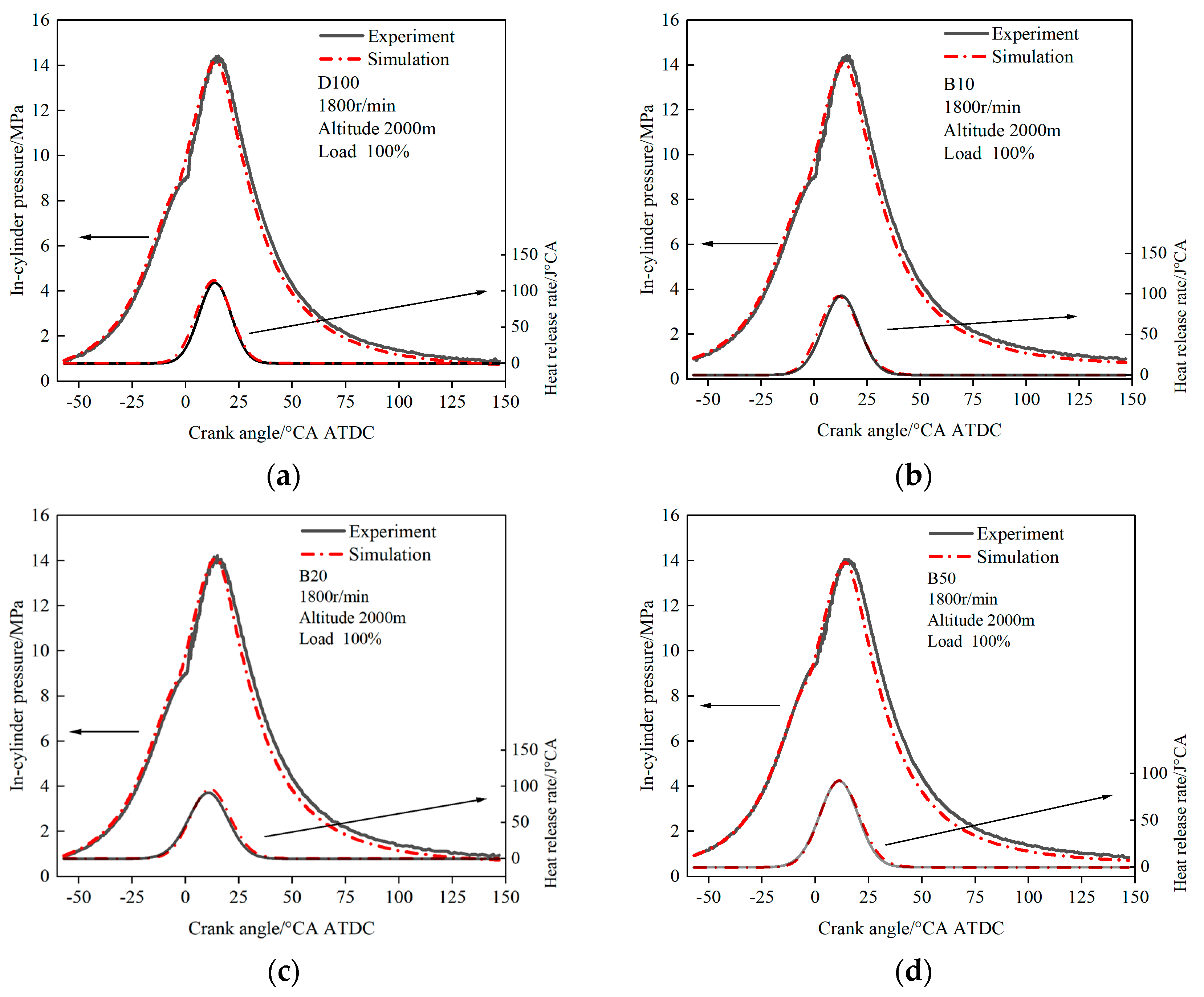
2.4. Validation of the Model

The initial boundary conditions were incorporated into the selected computational model, and numerical simulations were conducted for the prototype diesel engine at a condition of 1800 revolutions per minute (r/min) and 100% load, burning four types of fuels. The in-cylinder pressure and heat release rate obtained from the simulations were compared with experimental results, as shown in Figure 3. The simulation results were found to be in good agreement with the experimental data for both in-cylinder pressure and heat release rate. Therefore, the mathematical model used in this study exhibits satisfactory fitting effects for the diffusion combustion process of the diesel engine, with the data discrepancies between simulation and experiment limited to within 5%, ensuring the accuracy of the model for further calculations. In this paper, the positive and negative values of the crankshaft rotation angle indicate the position of the point relative to the top dead center (TDC) during the compression stroke, with negative values representing before TDC and positive values representing after TDC.

3. Results and Discussion

This study aims to investigate the combustion and emission characteristics of two different combustion systems in diesel engines operating in high-altitude regions when fueled with various blends of biodiesel. The primary fuels selected for this research are D100, B10, B20, and B50. A three-dimensional simulation approach is employed to study the combustion and emission characteristics of the two combustion systems when blending biodiesel in a high-altitude environment of 2000 m.

3.1. Combustion Characteristics

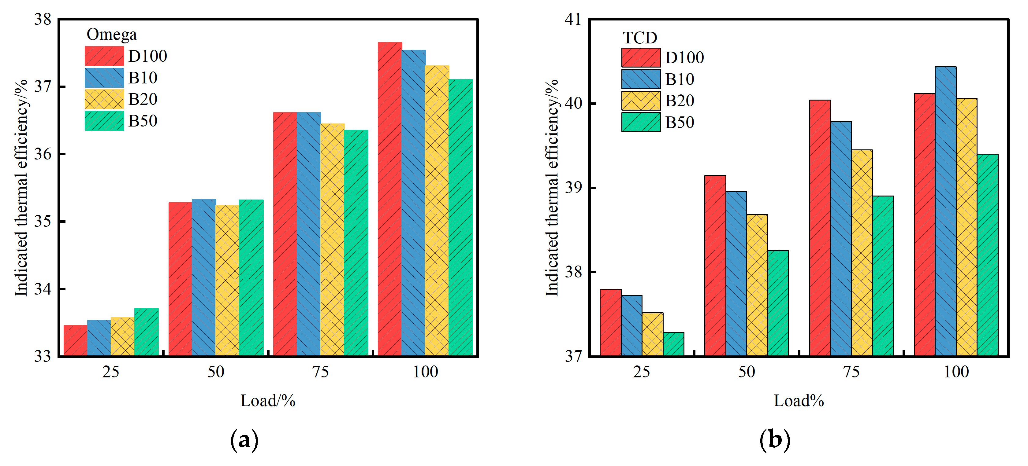
3.1.1. Indicative Thermal Efficiency

Indicated thermal efficiency (ITE) refers to the ratio of the actual thermal energy converted within the engine to the theoretical thermal energy of complete fuel combustion, and it is a key parameter for evaluating the performance of internal combustion engines. Figure 4 illustrates the ITE of the Omega combustion system and the TCD combustion system at loads of 25%, 50%, 75%, and 100% under a rotational speed of 1800 revolutions per minute (rpm). As depicted in Figure 4a, the ITE of the Omega combustion system increases with the rise in load. At low loads, the ITE of the Omega combustion system also increases as the proportion of biodiesel in the blended fuel increases. At medium loads, the ITE first rises, then decreases, and finally rises again with the increase in the biodiesel blending ratio. However, at high loads and full load, the ITE decreases as the biodiesel blending ratio increases. This indicates that for the Omega combustion chamber structure, at low loads, the higher the biodiesel blending ratio, the higher the ITE of the combustion system; whereas at high loads and full load, the lower the biodiesel blending ratio, the higher the ITE of the combustion system.
As illustrated in Figure 4b, the ITE of the TCD combustion system also increases with the increase in load, but it decreases with the increase in the proportion of biodiesel in the blended fuel. Notably, at full load, B10 exhibits a higher ITE than pure diesel. This suggests that in the TCD combustion system, regardless of the load variation, an increase in the biodiesel blending ratio typically leads to a reduction in ITE.
As observed in Figure 4c, the ITE of both combustion systems increases with the increase in load. Notably, the TCD combustion system consistently exhibits a higher ITE than the Omega combustion system under all tested conditions, regardless of the type of diesel used. Furthermore, as the proportion of biodiesel in the blended fuel increases, the rate of increase in the ITE of the TCD combustion system relative to the Omega combustion system is moderated. Specifically, when using D100 diesel, the TCD combustion system’s ITE was 12.96%, 10.97%, 9.36%, and 6.54% higher than that of the Omega combustion system at loads of 25%, 50%, 75%, and 100%, respectively. With B10 diesel, these differences were 12.49%, 10.28%, 8.64%, and 7.71%, respectively. When B20 diesel was utilized, the differences further decreased to 11.98%, 9.77%, 8.23%, and 7.39%, respectively. With B50 diesel, the differences were 10.59%, 8.31%, 7.02%, and 6.81%, respectively. These data suggest that as the biodiesel proportion increases, the relative advantage of the TCD combustion system in enhancing ITE diminishes. However, even at the highest biodiesel content, the ITE of the TCD combustion system remains superior to that of the Omega combustion system.
As illustrated in Figure 4d, the ITE of both combustion systems decreases with the increase in the proportion of biodiesel in the blended fuel and increases with the increase in load. This variation is attributed to the lower heating value of biodiesel itself. As the proportion of biodiesel in the blended fuel increases, the heating value of the blended fuel gradually decreases relative to pure diesel, leading to a reduction in the ITE of both combustion systems. Furthermore, the ITE of the TCD combustion system is higher than that of the Omega combustion system, which can be attributed to the unique geometric structure of the combustion chamber in the TCD system. This structure maximizes the utilization of air within the combustion chamber, enhances the air utilization rate, improves combustion performance, and consequently elevates the ITE of the TCD combustion system. The ITE of both combustion systems increases with the increase in load, which may be due to the fact that the thermal efficiency of the combustion system may have reached its peak at partial and full load conditions. Under these load conditions, the combustion system can more effectively utilize fuel and energy, thereby reducing energy loss.

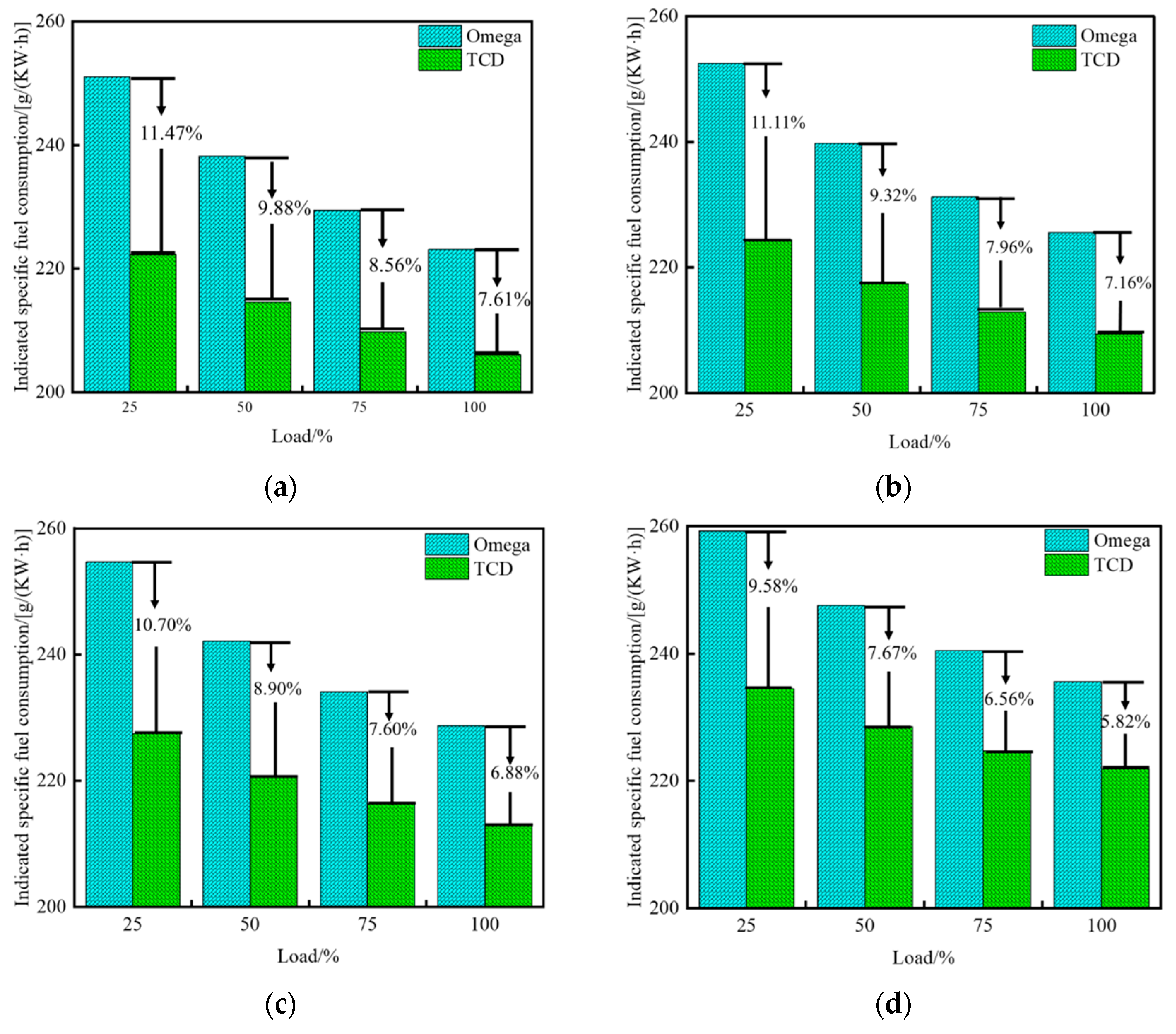
3.1.2. Indicated Specific Fuel Consumption

The indicated specific fuel consumption (ISFC) refers to the amount of fuel consumed per unit of indicated work, which is one of the important indicators for assessing the fuel efficiency and economy of an engine. Figure 5 illustrates the ISFC for the Omega combustion system and the TCD combustion system at 25%, 50%, 75%, and 100% load under a rotational speed of 1800 revolutions per minute (rpm). From the figure, it can be observed that the ISFC for both combustion systems decreases with the increase in load. Notably, the ISFC of the TCD combustion system is consistently lower than that of the Omega combustion system under all tested conditions, regardless of the type of diesel used. Furthermore, as the proportion of biodiesel in the blended fuel increases, the rate of decrease in the ISFC of the TCD combustion system relative to the Omega combustion system slows down. Specifically, when using D100 diesel, the ISFC of the TCD combustion system was 11.47%, 9.88%, 8.56%, and 7.61% lower than that of the Omega combustion system at loads of 25%, 50%, 75%, and 100%, respectively. With B10 diesel, these differences were 11.11%, 9.32%, 7.96%, and 7.16%, respectively. When B20 diesel was used, the differences further decreased to 10.70%, 8.90%, 7.60%, and 6.88%, respectively. With B50 diesel, the differences were 9.58%, 7.67%, 6.56%, and 5.82%, respectively. These data indicate that as the proportion of biodiesel increases, the relative advantage of the TCD combustion system in reducing ISFC diminishes. However, even at the highest biodiesel content, the ISFC of the TCD combustion system remains lower than that of the Omega combustion system.
As depicted in Figure 5e, the ISFC of both combustion systems increases with the proportion of biodiesel in the blended fuel and decreases with the increase in load. This is attributed to the fact that the heating value of biodiesel is relatively lower than that of diesel. As the proportion of biodiesel in the blended fuel increases, the heating value of the blended fuel decreases, leading to an increase in the ISFC of the combustion system. The ISFC of the TCD combustion system is lower than that of the Omega combustion system due to the unique geometric structure of the combustion chamber in the TCD system. In the TCD combustion system, the distinctive protrusion design diverts the fuel jet injected into the combustion chamber into the inner and outer chambers, enhancing the air utilization rate within the combustion chamber, thereby improving combustion performance and reducing the ISFC of the combustion system.
Figure 6a,b illustrates the equivalence ratio distribution at different crankshaft angles for the two combustion systems when blending biodiesel at 25% and 100% load, respectively. As observed from the figures, at a 25% load, the fuel front in the Omega combustion system begins to impinge on the wall at a crankshaft angle of −5 °CA ATDC, whereas the TCD combustion system has not yet encountered the wall. With the progression of the fuel injection process and the downward movement of the piston, at a crankshaft angle of 5 °CA ATDC, in the Omega combustion system, the fuel, after impinging on the wall, is directed by the in-cylinder airflow and the guiding effect of the combustion chamber wall, causing the fuel jet to flow into the bottom of the combustion chamber and the crevice space. During the fuel injection process, the fuel is primarily distributed along the axis of the injector nozzle, the bottom of the combustion chamber, and the crevice space, indicating that the fuel distribution within the combustion chamber space is not extensive. After the end of the fuel injection, as the combustion reaction proceeds, there is a noticeable reduction in the air–fuel equivalence ratio.
In the TCD combustion system, the fuel jet, under the guidance of the annular protrusion, develops in both the inner and outer chambers. The fuel flowing into the inner chamber spreads towards the central region of the combustion chamber through the bottom arc of the combustion chamber, while the fuel flowing into the outer chamber develops along the shallow pan bottom and collides with the side wall, forming a jet that develops towards the bottom of the cylinder head and spreads around the area of the cylinder head bottom, thereby expanding the fuel diffusion area and improving the quality of the fuel–air mixture. Due to the higher kinematic viscosity, density, and surface tension of biodiesel itself, as the proportion of biodiesel in the blended fuel increases, the kinematic viscosity, density, and surface tension of the blended fuel also increase, leading to a deterioration in the in-cylinder equivalence ratio distribution of the blended fuel in both combustion systems compared to that of pure diesel.

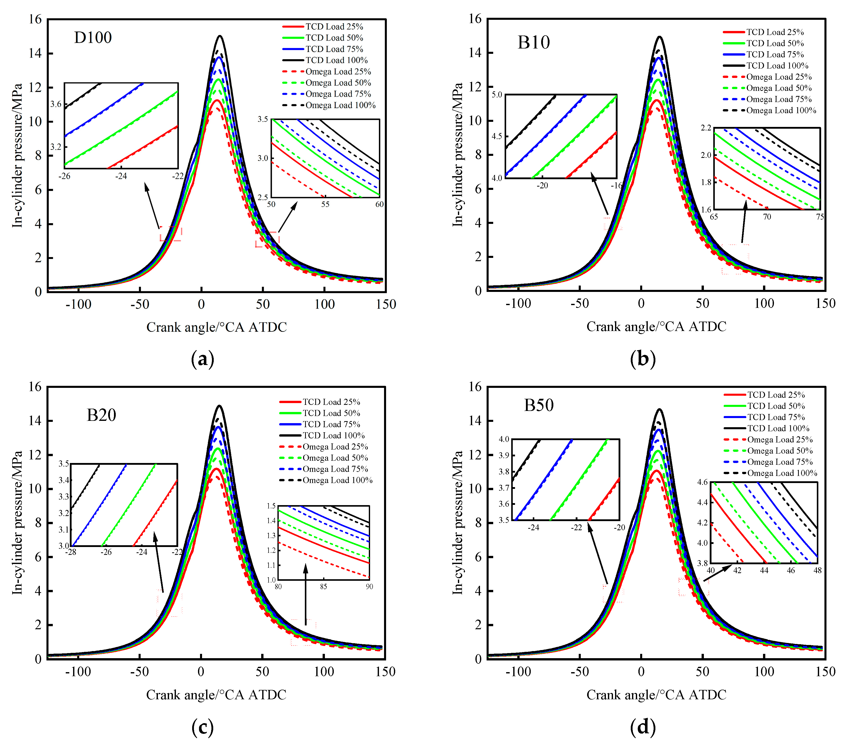
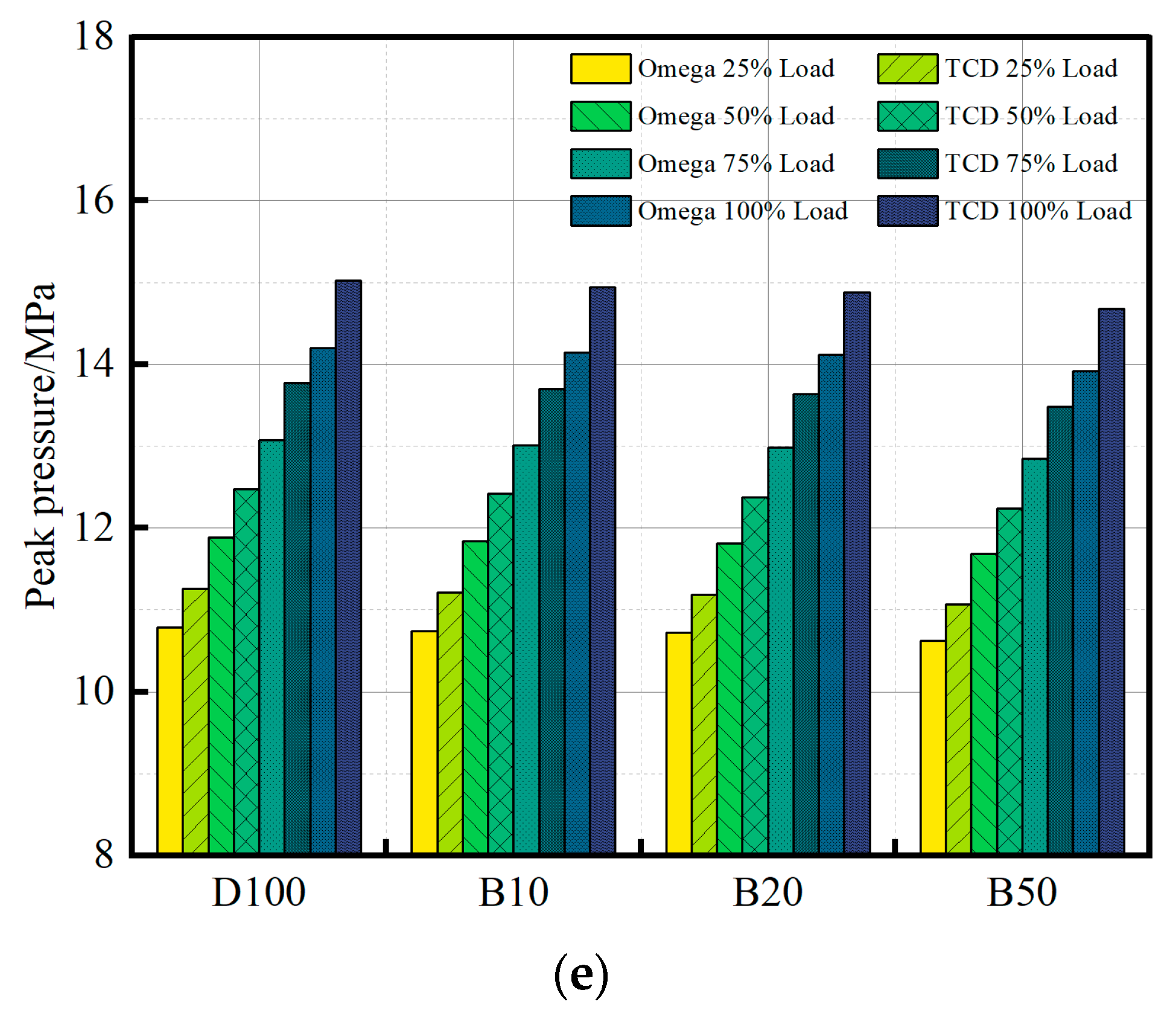
3.1.3. In-Cylinder Pressure

Cylinder pressure refers to the gas pressure within the combustion chamber that arises due to the combustion of fuel. This pressure reaches a peak during the combustion process, known as the peak cylinder pressure. The peak cylinder pressure is dependent on the combustion rate during the premixed combustion phase and is influenced by operating conditions and the composition of the fuel–air mixture [39]. This pressure is one of the key parameters in the engine’s working cycle and has a significant impact on the engine’s performance and efficiency. Figure 7a–e illustrates the in-cylinder pressures of the two combustion systems when co-firing biodiesel at different loads. It can be observed from Figure 7a–d that within the range of crankshaft rotation from −28 °CA ATDC to −20 °CA ATDC, the in-cylinder pressure curves of both combustion systems almost coincide. However, the in-cylinder pressure of the TCD combustion system is slightly higher than that of the Omega combustion system. At a crankshaft rotation of 5 °CA ATDC, the in-cylinder pressures of both combustion systems reach their maximum values, which increase with the increase in load. Regardless of the load condition and the type of fuel used, the peak in-cylinder pressure of the TCD combustion system is consistently higher than that of the Omega combustion system. As the engine operates and the piston continues to move downward, the cylinder volume increases, leading to a decrease in in-cylinder pressure. During the pressure drop phase, the in-cylinder pressure curves of the two combustion systems are relatively parallel, and the in-cylinder pressure of the TCD combustion chamber remains higher than that of the Omega combustion chamber, with the difference between the two becoming more pronounced after reaching the peak in-cylinder pressure.
As depicted in Figure 7e, the peak in-cylinder pressures of both combustion systems increase with the increase in load but decrease with the increase in the proportion of biodiesel in the blended fuel. Regardless of the load condition and the type of fuel used, the peak pressure in the TCD combustion system is consistently higher than that in the Omega combustion system. This is because the in-cylinder pressure is determined by the gas pressure produced by the combustion of fuel. Biodiesel has a lower heating value compared to diesel, and thus its combustion releases less energy that can be converted into gas pressure. With the increase in load, more fuel is required to burn in order to provide additional power or torque. This typically leads to a greater amount of air and fuel entering the cylinder, releasing more energy upon combustion, and consequently increasing the in-cylinder pressure. The TCD combustion system, due to its unique dome-shaped structure, can improve the utilization rate of in-cylinder air and enhance combustion performance, thereby increasing the in-cylinder pressure.

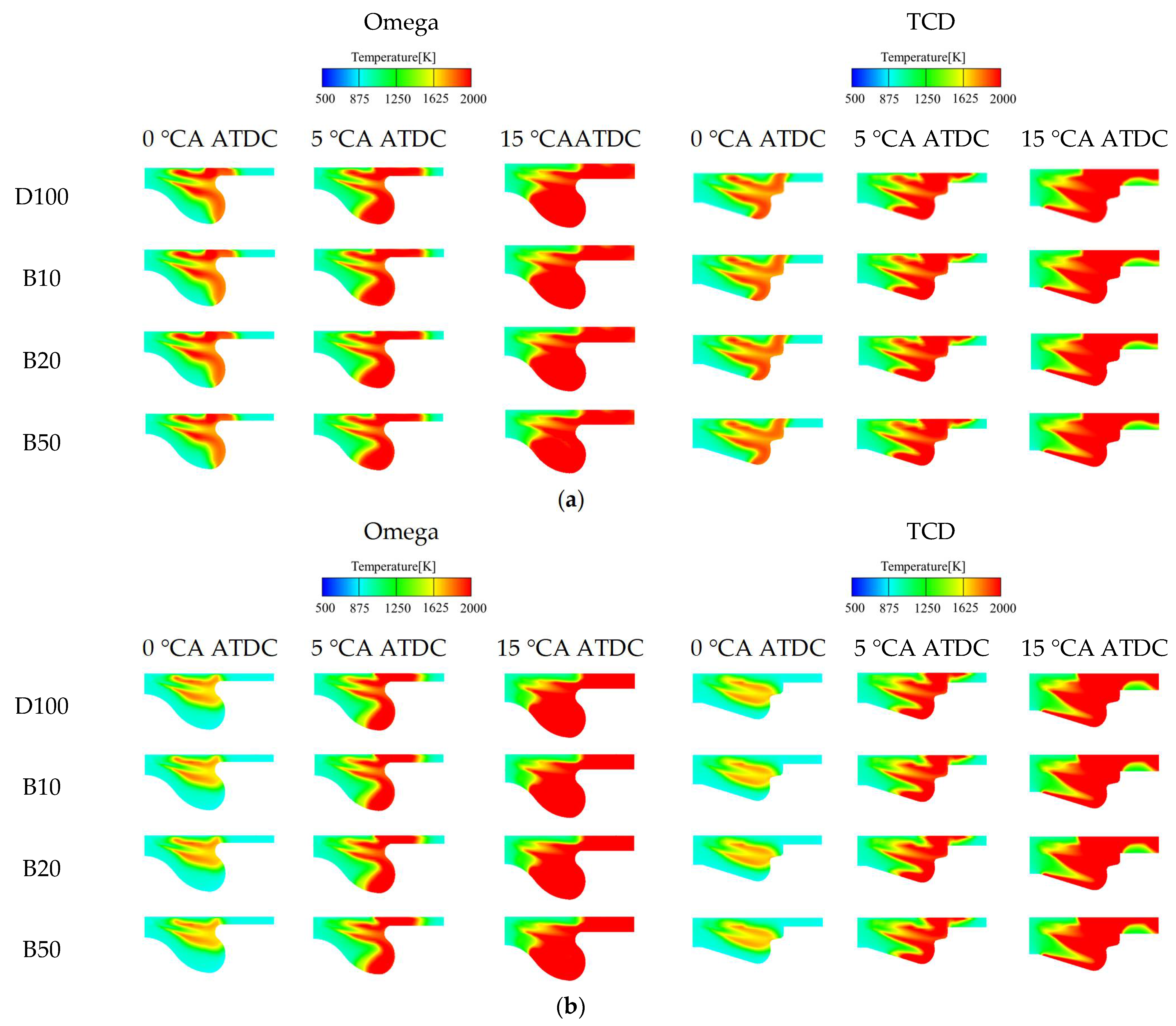
3.1.4. In-Cylinder Temperature

The in-cylinder temperature refers to the temperature of the mixture of gases (air and fuel) or combustion products within the engine during the combustion process, which typically reaches its peak within the engine’s combustion chamber, especially during the combustion phase. The in-cylinder temperature is one of the key parameters for engine performance and efficiency.
Figure 8a–f shows the in-cylinder temperature variations of the two combustion systems when blending biodiesel at different loads. It can be observed from Figure 8a–d that at the top dead center (TDC), the in-cylinder temperatures of both combustion systems begin to rise rapidly. Within the crankshaft rotation period from 8 °CA ATDC to 12 °CA ATDC, the in-cylinder temperature curves at different loads start to intersect. Prior to these intersections, the in-cylinder temperature curves at lower loads exhibit higher values. After the intersections, the in-cylinder temperature curves rise as the load increases. At a crankshaft rotation of 20 °CA ATDC, the in-cylinder temperature curves of both combustion systems reach their maximum values. The maximum in-cylinder temperature increases with the increase in load, and under all load conditions and fuel types, the maximum in-cylinder temperature of the TCD combustion system is consistently higher than that of the Omega combustion system.
As illustrated in Figure 8e, the maximum in-cylinder temperatures for both combustion systems increase with the augmentation of load and decrease with the increment of biodiesel proportion in the blended fuel. From Figure 8f, it can be seen that the crank angle corresponding to the maximum in-cylinder temperatures of both combustion systems advances with increasing load and remains relatively stable as the proportion of biodiesel in the blended fuel increases. Furthermore, regardless of the load conditions, the maximum in-cylinder temperature of the TCD combustion system is consistently higher than that of the Omega combustion system. The in-cylinder temperatures of both combustion systems rise with the increase in load, as a greater amount of fuel is required for combustion to provide additional power or torque. This typically leads to a higher intake of air and fuel into the cylinder, releasing more energy upon combustion, thereby increasing the in-cylinder temperature. Moreover, the maximum in-cylinder temperatures of both combustion systems decrease with the increase in the proportion of biodiesel in the blended fuel. This is attributed to the lower heating value of biodiesel compared to diesel, resulting in a relatively weaker capacity to convert the energy released during combustion into gas temperature, leading to a reduction in in-cylinder temperature. On the other hand, the TCD combustion system, due to its unique geometric structure, enhances the utilization rate of in-cylinder air, thereby improving the combustion performance within the cylinder, which results in higher in-cylinder temperatures compared to the Omega combustion system.
Figure 9a,b depicts the temperature distribution at different crankshaft angles for two combustion systems when blending biodiesel at 25% and 100% load, respectively. As observed from the figures, at the top dead center (TDC), the fuel jets in both combustion systems have already impinged on the wall. In the Omega combustion system, the fuel jet is primarily distributed at the bottom of the combustion chamber and the crevice space. In this region, the fluid temperature is the highest, and the temperature is also relatively high in the areas where the spray flame has passed. Conversely, in areas where the spray flame has not propagated, the fluid temperature gradually decreases. Similarly, in the TCD combustion system, the fuel jet, guided by the annular protrusion, flows into both the inner and outer chambers. The fuel flowing into the inner chamber spreads towards the central region of the combustion chamber through the bottom arc, while the fuel flowing into the outer chamber develops along the shallow pan bottom, collides with the side wall, and forms a jet that develops towards the bottom of the cylinder head, spreading around the area of the cylinder head bottom where the fluid temperature is also relatively high due to the presence of the fluid flow. As the crankshaft rotates and the piston moves downward, at a crankshaft angle of 15 °CA ATDC, the fuel in both combustion systems gradually fills the entire combustion chamber. Due to the lower heating value of biodiesel itself, as the proportion of biodiesel in the blended fuel increases, the heating value of the blended fuel also decreases, leading to a deterioration in the in-cylinder temperature distribution of the blended fuel in both combustion systems compared to that of pure diesel. Compared to the Omega combustion system, the TCD combustion system, due to its unique geometric structure, results in a broader fuel diffusion area, more uniform fuel–air mixing, and more complete fuel combustion, leading to higher in-cylinder temperatures.

3.2. Emission Characteristics

During the operation of diesel engines, the exhaust gases emitted contain a variety of harmful substances. These exhaust gases are primarily due to incomplete combustion, resulting in the production of CO, CO2, HC, etc., as well as particulate matter (PM), soot, and NOx generated from the incomplete combustion of fuel [40]. These harmful gases can cause environmental pollution and affect human health [41,42]. Therefore, this section aims to study the emission patterns of pollutants when co-firing biodiesel in different combustion systems through simulation.

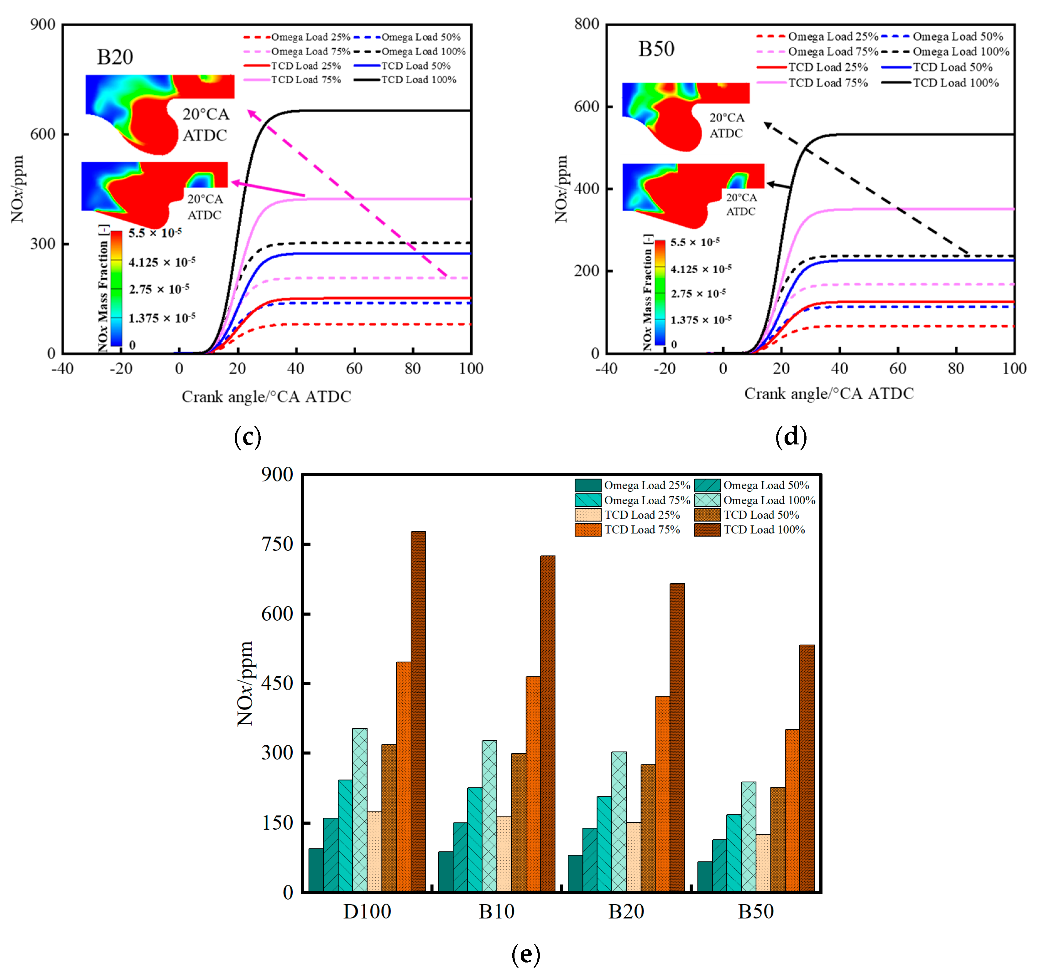
3.2.1. NOx Emissions

The exhaust gases from diesel engines are predominantly composed of NOx, with NO being the major constituent and the minor fraction being NO2. The NO molecule contains free radicals, making it an extremely unstable and weakly toxic gas. Upon contact with oxygen, NO can be rapidly oxidized to NO2, which is a highly irritating and toxic gas posing significant health hazards. In the exhaust emissions from diesel engines, NO2 constitutes only a small portion, with the majority being NO. This is primarily because NO2 decomposes into NO at high temperatures. At approximately 650 °C, NO2 completely decomposes into O2 and NO. Due to the high in-cylinder temperatures in diesel engines, the focus in the discussions of nitrogen oxide emissions is mainly on NO. NOx emissions from diesel engines primarily consist of NO as the dominant component, with minor quantities of NO2. The formation of these pollutants in compression-ignition engines is principally governed by thermal NO mechanisms, with the Zeldovich mechanism representing the predominant pathway [43,44,45]. This oxidation sequence, occurring through chain-branching reactions in high-temperature combustion zones, can be formally described by the following elementary reactions:
N 2 + O N O + N
N + O 2 N O + O
N + O H N O + H
The formation mechanism of Zeldovich NO is primarily attributed to the high stability of the nitrogen molecule, which possesses a strong trivalent bond. This bond requires substantial thermal excitation and a high activation energy to initiate the forward reaction. According to the Zeldovich mechanism, NO formation is largely independent of the type of fuel used and is instead governed by the presence and interactions of five key reactive species: O, H, OH, N, and O2. The process is highly sensitive to local in-cylinder conditions, particularly high temperatures, low air–fuel ratios, and prolonged residence times at elevated temperatures [46]. Consequently, the maximum in-cylinder temperature plays a critical role in determining NOx emissions [47]. Figure 10a–e shows the NOx emissions of the two combustion systems under different loads when biodiesel is blended.
From Figure 10a–d, it can be observed that the NOx emissions of both combustion systems increase with increasing load. Regardless of the load condition or the type of fuel used, the TCD combustion system consistently exhibits higher NOx emissions than the Omega combustion system, and the difference between the two becomes more pronounced as the load increases. This is because as the load increases, more fuel must be burned to meet the required power or torque output. This typically results in a greater amount of air and fuel entering the cylinder, releasing more energy during combustion and thereby increasing the in-cylinder temperature. Higher temperatures promote the formation of NOx. Due to its unique geometric structure, the TCD combustion system improves in-cylinder combustion performance, leading to higher combustion temperatures compared to the Omega system. As a result, the NOx emissions of the TCD combustion system are higher than those of the Omega system.
By examining the NOx mass distribution at 20 °CA ATDC in both combustion systems, we can identify the following characteristics: In the Omega combustion system, NOx is primarily formed at the bottom of the combustion chamber and in the crevice space. After fuel is injected from the nozzle, the spray impinges on the combustion chamber wall, then splits and flows into the bottom of the combustion chamber and the crevice space. In the TCD combustion system, NOx is mainly generated in the inner and outer chambers of the combustion chamber as well as in the crevice space. After injection, the fuel spray strikes the annular ridge, and then splits into the inner and outer chambers. The spray entering the outer chamber continues to impinge on the side wall, forming a jet that develops toward the cylinder head and spreads around the surrounding region under the head.
As shown in Figure 10e, the NOx emissions of both combustion systems increase with increasing load but decrease as the proportion of biodiesel in the blended fuel increases. This is consistent with the trend observed in the study by Al-lwayzy and Yusaf [48]. This reduction may be attributed to several factors: First, biodiesel has a higher oxygen content, lower sulfur content, and lower heating value compared to conventional diesel. As the proportion of biodiesel increases in the blend, the overall oxygen content increases, while sulfur content and heating value decrease. These combined effects help lower the combustion temperature, thereby reducing NOx formation. On the other hand, biodiesel has a higher viscosity than diesel, which may lead to slower flow through the injector. This reduced flow can decrease the injection rate and affect the atomization quality of the fuel. Compared to diesel, biodiesel may mix less rapidly and uniformly with air. This non-uniform mixing can result in local oxygen deficiency, further reducing combustion temperatures and suppressing NOx formation.

3.2.2. Soot Emissions
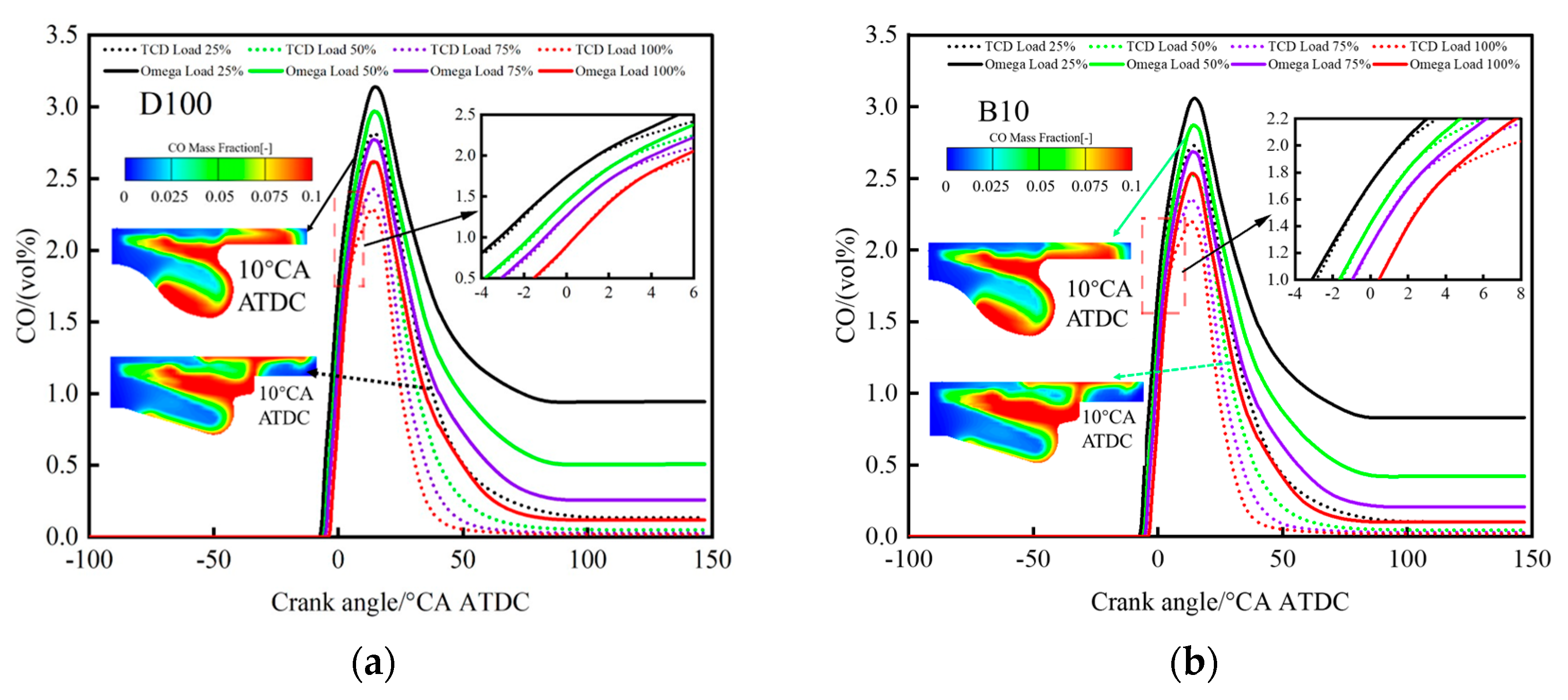
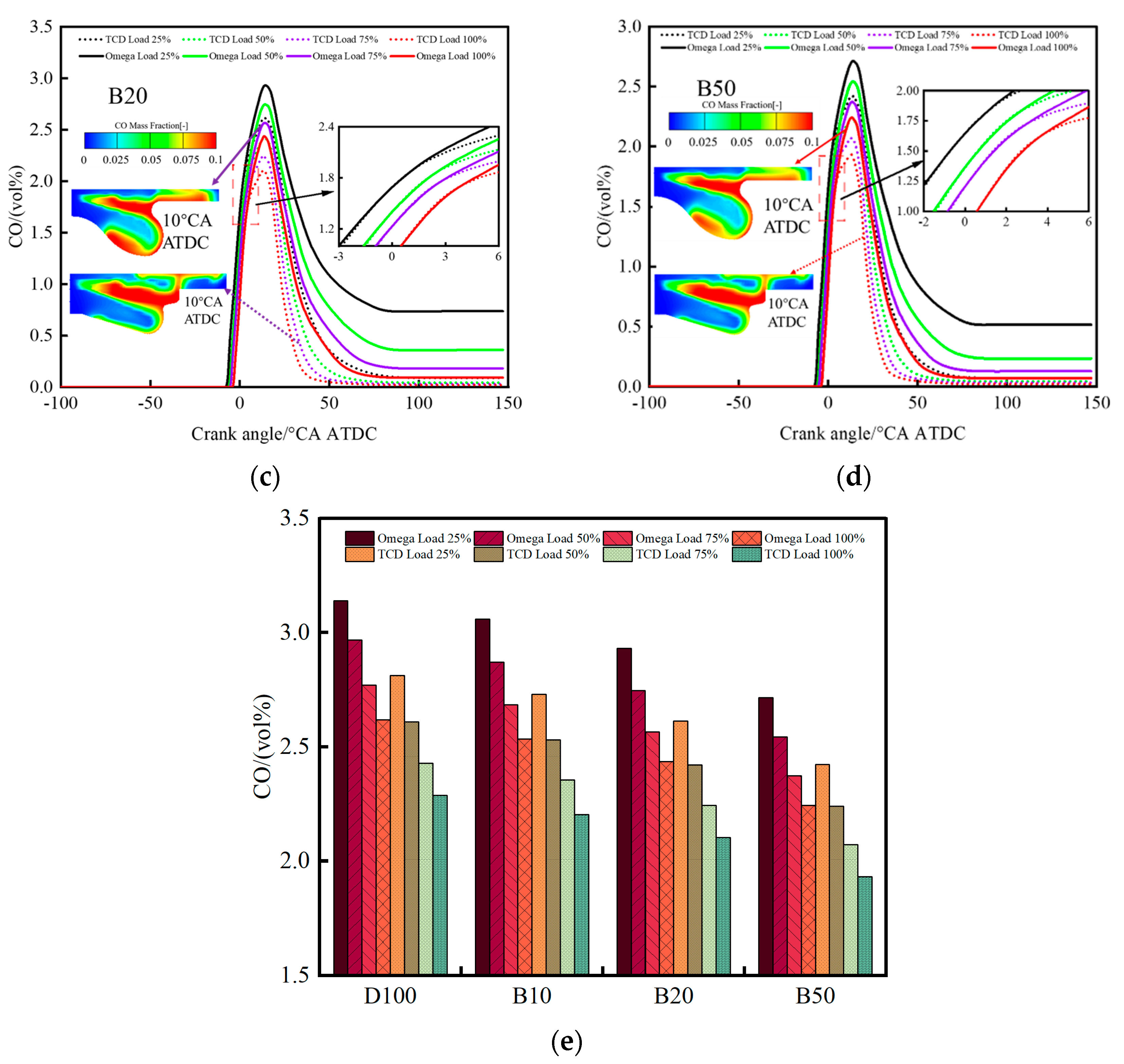
Soot in diesel engine exhaust is one of the major harmful emissions, with a highly complex composition including soot particles, ionic species such as sulfates and nitrates, and ash. Among these, soot particles are the primary component. Soot poses significant health and environmental risks due to its fine particulate nature and is mainly formed under high-temperature, oxygen-deficient conditions. When the fuel–air mixture is uneven or the combustion temperature is excessively high, soot formation tends to increase [49,50]. Figure 11a–e illustrates the soot emissions of the two combustion systems under various load conditions when co-fueled with biodiesel.
From Figure 11a–d, it can be seen that the soot emissions of both combustion systems decrease as load increases. Within the crank angle range of −2 °CA ATDC to 5 °CA ATDC, the soot emission curves of both systems intersect under all four load conditions. Before the intersection point, the TCD combustion system generally exhibits slightly higher soot emissions than the Omega system. After the intersection, the Omega system shows higher soot emissions, and the difference between the two widens progressively with increasing crank angle. The soot emission curve of the TCD system peaks at 10°CA ATDC, while that of the Omega system peaks at 20 °CA ATDC. Both systems reach their minimum soot emissions at 40 °CA ATDC, after which the levels no longer increase significantly. Notably, the soot emission of the TCD system approaches zero after 40 °CA ATDC, whereas the Omega system maintains a level of 0–50 ppm beyond that point. The observed decrease in soot emissions with increasing load may result from several factors. First, higher loads may enhance the combustion chamber’s efficiency, leading to a more homogeneous fuel–air mixture and thus more complete combustion. Second, increased load typically results in elevated combustion temperatures, which promote complete fuel oxidation and reduce soot formation from incomplete combustion.
By examining the soot mass distribution at 10 °CA ATDC for both systems, the following observations can be made: In the Omega combustion system, soot mainly forms at the bottom of the combustion chamber and in the crevice space. After fuel injection, the spray impinges on the combustion chamber wall and then splits into flows toward the combustion chamber bottom and crevice regions. In the TCD combustion system, soot is primarily generated in the inner and outer chambers of the combustion chamber as well as near the cylinder head surface. After injection, the spray strikes the annular ridge and splits off into the inner and outer chambers. The portion directed to the outer chamber continues to impinge on the side wall, forming a jet that develops toward the cylinder head and spreads around its surface. As the load increases and the proportion of biodiesel in the fuel blend rises, soot formation in both the crevice space and the combustion chamber bottom region of the Omega system is significantly reduced. Similarly, soot formation in the inner and outer chambers of the TCD system also decreases with increasing load and biodiesel ratio.
Figure 11e shows that soot emissions for both combustion systems decrease with increasing load and further decrease as the biodiesel blending ratio increases. This is consistent with the trend observed in the study by Knothe et al. [51]. In particular, the TCD combustion system consistently exhibits lower soot emissions than the Omega system under all load conditions and at any biodiesel blending ratio. Several reasons may account for this reduction: (1) Biodiesel typically has a higher oxygen content, which promotes oxidation during combustion and reduces soot formation from incomplete combustion. (2) Biodiesel has a lower carbon-to-hydrogen (C/H) ratio than conventional diesel, which means less energy is released per unit of fuel, leading to reduced soot generation. (3) Biodiesel has a higher cetane number, which enables quicker and more complete combustion, thereby reducing soot. (4) The TCD combustion system improves in-cylinder air utilization, allowing for a more uniform fuel–air mixture and more complete combustion, effectively suppressing soot formation.

3.2.3. CO Emissions

During the combustion process, if the air and fuel are not mixed sufficiently or if there is an insufficient supply of oxygen, hydrocarbon fuels struggle to achieve complete combustion. This incomplete combustion results in the production of a toxic gas, carbon monoxide (CO). The formation of CO is related to various factors, including in-cylinder temperature, oxygen concentration, and combustion duration. CO, carbon monoxide, is a colorless and odorless toxic gas that, once inhaled, binds with hemoglobin, leading to oxygen deprivation and poisoning in the human body. The CO in vehicular engine exhaust is typically due to a low-temperature, oxygen-deficient environment, where carbon (C) and oxygen (O) react without fully forming carbon dioxide (CO2), instead producing the intermediate product CO. Consequently, gasoline engines are prone to CO production under rich mixture conditions, while diesel engines, with their excess air coefficient generally greater than 1, produce less CO. Figure 12a–e illustrates the CO emissions when blending biodiesel in the two combustion systems under different load conditions.
As illustrated in Figure 12a–d, the CO emissions from both combustion systems decrease with increasing load. Within the range of the crankshaft rotation angle from −4°CA ATDC to 6°CA ATDC, the CO formation curves for the two combustion systems under four different loads coincide. Prior to the point of coincidence, the CO formation curve of the Omega combustion system approaches that of the TCD combustion system but remains slightly higher. After the point of coincidence, the CO formation curve of the Omega combustion system begins to exceed that of the TCD combustion system, and this difference gradually increases with the increase in the crankshaft rotation angle.
Beyond a crankshaft rotation angle of 50°CA ATDC, the CO formation curve for the TCD combustion system ceases to increase and remains parallel within a range of 0–0.25 Vol%. With the increase in load, the CO formation curve of the TCD combustion system gradually approaches zero. However, for the Omega combustion system, beyond a crankshaft rotation angle of 80 °CA ATDC, the CO formation curve also stops increasing and remains parallel within a range of 0.15–1.25 Vol%. As the load increases, the CO formation curve of the Omega combustion system gradually decreases. The reduction in CO emissions with increasing load may be attributed to two possible reasons. Firstly, as the load increases, the engine requires more energy to meet the demand, leading to more complete combustion, which helps to reduce CO produced from incomplete combustion. Secondly, during high-load operation, the engine temperature typically rises, which enhances combustion efficiency, as higher temperatures can promote the oxidation reactions of the fuel, thereby reducing the formation of CO.
By looking at the CO mass distribution plots of the two combustion systems at a crankshaft turn angle of 10 °CA ATDC, we can find the following characteristics: in the Omega combustion system, CO is generated mainly in the bottom and top gaps of the combustion chamber’s pit region, whereas in the TCD combustion system, CO is mainly generated in the inner and outer chamber regions of the combustion chamber as well as the bottom surface of the cylinder head. As the load increases and the percentage of biodiesel in the fuel blend increases, the CO generation in the bottom region and top gap region of the Omega combustion chamber decreases significantly. Similarly, in the TCD combustion system, CO generation in the inner and outer chamber regions decreased with increasing load and biodiesel percentage.
Figure 12e shows that the CO emissions of both combustion systems decrease with increasing load and increasing biodiesel proportion in the blend. Moreover, under the same load conditions and fuel blend, the TCD combustion system exhibits lower CO emissions compared to the Omega combustion system. This can be attributed to the higher oxygen content of biodiesel, which promotes oxidation reactions during combustion, leading to reduced CO formation. Additionally, the TCD combustion system enhances air utilization within the cylinder, resulting in a more homogeneous air–fuel mixture and more complete fuel combustion, thereby suppressing CO formation.

4. Conclusions

This paper utilizes the AVL FIRE software to construct prototype Omega and TCD combustion chambers (both optimized). These chambers were then simulated using four different fuels: D100 (pure diesel), B10 (10% biodiesel by volume and 90% diesel by volume), B20 (20% biodiesel by volume and 80% diesel by volume), and B50 (50% biodiesel by volume and 50% diesel by volume). The simulations were conducted under four load conditions: 25%, 50%, 75%, and 100%. The following conclusions were drawn from the simulations:
(1) In the Omega combustion system, at low loads, the ITE increases with the proportion of biodiesel in the blended fuel. At medium loads, the trend of ITE is more complex: as the blend ratio of biodiesel increases, ITE first rises, then decreases, and finally rises again. At high loads and full load, the ITE decreases with the increase of the biodiesel blend ratio.
However, in the TCD combustion system, ITE typically increases with the increase of load. Unlike the Omega combustion system, the ITE in the TCD combustion system decreases with the increase of the proportion of biodiesel in the blended fuel. Notably, at full load, B10 (a blend of biodiesel at 10% concentration) exhibits a higher ITE than pure diesel, which is contrary to the trend observed at medium and high loads.
(2) The TCD combustion system, due to its unique protruding structure, optimizes fuel distribution, enhancing air–fuel mixing quality and air utilization. This, in turn, leads to improved combustion performance, resulting in higher in-cylinder peak pressure and temperature, as well as a higher Ignition Timing (ITE) compared to the Omega system.
(3) The TCD combustion system exhibits lower ISFC compared to the Omega system. This is primarily attributed to the geometrical advantages of its combustion chamber, particularly the protruding design, which enhances air utilization and combustion efficiency. Increasing the biodiesel proportion leads to an increase in ISFC due to its lower heating value compared to diesel. However, increasing the load contributes to a decrease in ISFC.
(4) The TCD combustion system exhibits higher NOx emissions compared to the Omega system. This is primarily due to the combustion chamber design, which promotes uniform fuel distribution and enhanced air utilization, leading to increased in-cylinder temperatures and favorable conditions for NOx formation. However, as the proportion of biodiesel in the fuel blend increases, its higher oxygen content, lower sulfur content, and lower heating value contribute to reduced combustion temperatures, thereby mitigating NOx emissions. Increasing the load leads to increased NOx emissions.
(5) The TCD combustion system exhibits lower soot and CO emissions compared to the Omega system. This is attributed to the combustion chamber geometry, which promotes uniform fuel distribution and efficient air utilization, thereby suppressing the formation of soot and CO. The high oxygen content of biodiesel contributes to reduced soot and CO formation in low-oxygen environments. As the proportion of biodiesel in the fuel blend increases, along with increasing load, the emissions of soot and CO further decrease.
(6) This study was conducted under plateau environmental conditions, focusing on performance tests at various load levels based on the engine’s maximum torque speed. Future work will encompass a broader range of engine speeds and transient conditions. Additionally, a combination of simulation and experimental approaches will be employed to further explore optimization strategies for combustion chamber design and assess the application potential of biodiesel-blended fuels under plateau conditions.

Author Contributions

Conceptualization, Z.W.; methodology, Z.W.; software, Z.W.; validation, Y.C.; formal analysis, Z.W.; investigation, C.H.; resources, J.L.; data curation, Z.W.; writing—original draft preparation, Z.W.; writing—review and editing, D.W.; visualization, Z.W.; supervision, Y.N.; project administration, J.L.; funding acquisition, J.L. All authors have read and agreed to the published version of the manuscript.

Funding

This research was funded by the Agricultural Joint Special Program of the Yunnan Provincial Department of Science and Technology, grant numbers 202301BD070001-257 and 202301BD070001-077, and the Yunnan Provincial High-Level Talent Project, grant numbers YNWR-QNBJ-2018-066 and YNQR-CYRC-2019-001.

Data Availability Statement

The data presented in this study are available on request from the corresponding author.

Conflicts of Interest

The authors declare no conflicts of interest.

Abbreviations

The following abbreviations are used in this manuscript:
TCDTurbocharger, charge air cooling, diesel particle filter
B10A blend of 10% biodiesel and 90% diesel by volume
B20A blend of 20% biodiesel and 80% diesel by volume
B50A blend of 50% biodiesel and 50% diesel by volume
D100100% diesel by volume
ITEIndicated thermal efficiency
ISFCIndicated specific fuel consumption
DMEDimethyl ether
BTEBrake thermal efficiency
TRCCToroidal Re-entrant Combustion Chamber
HCCHemispherical Combustion Chamber
TCCToroidal Combustion Chamber
HPBHemispherical piston bowl
RPBRe-entrant piston bowl
LSPBLateral swirl piston bowl
DSPBDual swirl piston bowl
LDSPBLateral and dual swirl piston bowl
FSCSForced swirl combustion system
MSCSMulti-swirl combustion system
CFDComputational fluid dynamics
ATDCAfter top dead center
TDCTop dead center

References

  1. Shao, J.; Huang, S.; Lemus-Aguilar, I.; Ünal, E. Circular Business Models Generation for Automobile Remanufacturing Industry in China: Barriers and Opportunities. J. Manuf. Technol. Manag. 2019, 31, 542–571. [Google Scholar] [CrossRef]
  2. Wang, K.-H.; Su, C.-W.; Xiao, Y.; Liu, L. Is the Oil Price a Barometer of China’s Automobile Market? From a Wavelet-Based Quantile-on-Quantile Regression Perspective. Energy 2022, 240, 122501. [Google Scholar] [CrossRef]
  3. Sathiyamoorthi, E.; Lee, J.; Ramesh, M.D.; Nguyen, N.D.; Shanmuganathan, R. Biodiesel Production from Eggshells Derived Bio-Nano CaO Catalyst–Microemulsion Fuel Blends for up-Gradation of Biodiesel. Environ. Res. 2024, 260, 119626. [Google Scholar] [CrossRef]
  4. Li, W.; Liu, S.; Lu, C. An Evaluation Concentrated on Post-Peak Carbon Trend Scenarios Designing and Carbon Neutral Pathways in Hebei Province, China. J. Clean. Prod. 2024, 441, 140952. [Google Scholar] [CrossRef]
  5. Jamrozik, A.; Tutak, W. The Impact of Ammonia and Hydrogen Additives on the Combustion Characteristics, Performance, Stability and Emissions of an Industrial DF Diesel Engine. Appl. Therm. Eng. 2024, 257, 124189. [Google Scholar] [CrossRef]
  6. Hu, R.; Cai, T.; Xu, W. Exploring the Technology Changes of New Energy Vehicles in China: Evolution and Trends. Comput. Ind. Eng. 2024, 191, 110178. [Google Scholar] [CrossRef]
  7. Rasul, M.J.M.A.; Kim, J. Comprehensive Review and Comparison on Battery Technologies as Electric-Powered Source in Marine Applications. J. Energy Storage 2024, 88, 111509. [Google Scholar] [CrossRef]
  8. Hivert, L. Short-Term Break in the French Love for Diesel? Energy Policy 2013, 54, 11–22. [Google Scholar] [CrossRef]
  9. Hao, C.; Zhang, Z.; Wang, Z.; Bai, H.; Li, Y.; Li, Y.; Lu, Z. Investigation of Spray Angle and Combustion Chamber Geometry to Improve Combustion Performance at Full Load on a Heavy-Duty Diesel Engine Using Genetic Algorithm. Energy Convers. Manag. 2022, 267, 115862. [Google Scholar] [CrossRef]
  10. Wojcieszyk, M.; Kroyan, Y.; Kaario, O.; Larmi, M. Prediction of Heavy-Duty Engine Performance for Renewable Fuels Based on Fuel Property Characteristics. Energy 2023, 285, 129494. [Google Scholar] [CrossRef]
  11. Yuksel, T. Experimental Investigation of the Emission and Performance of Preheated and Unheated Garlic Methyl Ester Fuels and Diesel Fuel in a Diesel Engine. Process Saf. Environ. Prot. 2024, 185, 239–255. [Google Scholar] [CrossRef]
  12. Prak, D.L.; Cowart, J. Physical Properties and Diesel Engine Combustion of Blends of Alcohols with Military Jet Fuel JP-5. Fuel 2024, 371, 132070. [Google Scholar] [CrossRef]
  13. Gülcan, H.E. Effect of Intake Valve Lift and Binary Alcohol (Bioethanol+isobutanol) Addition on Energy, Exergy, Sustainability, Greenhouse Gas Impact and Cost Analysis in a Hydrogen/Diesel Dual Fuel Engines. Int. J. Hydrogen Energy 2024, 77, 450–471. [Google Scholar] [CrossRef]
  14. Liu, J.; Guo, Q.; Guo, J.; Wang, F. Optimization of a Diesel/Natural Gas Dual Fuel Engine under Different Diesel Substitution Ratios. Fuel 2021, 305, 121522. [Google Scholar] [CrossRef]
  15. Guo, W.; Wang, H.; Chen, H.; Yu, B.; Wang, Y.; Zhao, J. Performance and Safety of Transport Vehicles Fueled with Alternative Fuels in Plateau Environment: A Review. J. Traffic Transp. Eng. Engl. Ed. 2022, 9, 930–944. [Google Scholar] [CrossRef]
  16. Temizer, I.; Cihan, O. An Experimental Investigation of New Chamber Geometry on the Combustion Characteristics, Performance and Emissions in a Light-Duty Diesel Engine. Fuel 2023, 345, 128160. [Google Scholar] [CrossRef]
  17. Zhang, Y.; Zhong, Y.; Wang, J.; Tan, D.; Zhang, Z.; Yang, D. Effects of Different Biodiesel-Diesel Blend Fuel on Combustion and Emission Characteristics of a Diesel Engine. Processes 2021, 9, 1984. [Google Scholar] [CrossRef]
  18. Kawabe, T.; Inoue, K.; Mori, K.; Ishikawa, T.; Kobashi, Y.; Shibata, G.; Ogawa, H. Mechanism of the Reduction in Afterburning and Thermal Efficiency Improvement with Highly Oxygenated Fuels in Diesel Combustion. Int. J. Engine Res. 2023, 24, 4362–4372. [Google Scholar] [CrossRef]
  19. Ooi, J.B.; Rajanren, J.R.; Ismail, H.M.; Swamy, V.; Wang, X. Improving Combustion Characteristics of Diesel and Biodiesel Droplets by Graphite Oxide Addition for Diesel Engine Applications. Int. J. Energy Res. 2017, 41, 2258–2267. [Google Scholar] [CrossRef]
  20. Hao, Y.; Wang, G.; Wang, Q.; And, X.L. Numerical Simulation on Structural Optimization Design of Combustion Chamber of High Strength Diesel Engine. Energy Sources Part. Recovery Util. Environ. Eff. 2022, 44, 9682–9702. [Google Scholar] [CrossRef]
  21. Zou, R.; Liu, J.; Jiao, H.; Zhao, J.; Wang, N. Combined Effect of Intake Angle and Chamber Structure on Flow Field and Combustion Process in a Small-Scaled Rotary Engine. Appl. Therm. Eng. 2022, 203, 117652. [Google Scholar] [CrossRef]
  22. Chen, Y.; Li, X.; Li, X.; Zhao, W.; Liu, F. The Wall-Flow-Guided and Interferential Interactions of the Lateral Swirl Combustion System for Improving the Fuel/Air Mixing and Combustion Performance in DI Diesel Engines. Energy 2019, 166, 690–700. [Google Scholar] [CrossRef]
  23. Chen, Y.; Li, X.; Li, X.; Zhao, W.; Liu, F. Verifying the Wall-Flow-Guided Assumption of the Lateral Swirl Combustion System in DI Diesel Engines. Fuel 2020, 266, 117079. [Google Scholar] [CrossRef]
  24. Jaffar Al-Mulla, E.A.; Issam, A.M.; Al-Janabi, K.W.S. A Novel Method for the Synthesis of Biodiesel from Soybean Oil and Urea. Comptes Rendus Chim. 2015, 18, 525–529. [Google Scholar] [CrossRef]
  25. de Araújo, C.D.M.; de Andrade, C.C.; e Silva, E.D.S.; Dupas, F.A. Biodiesel Production from Used Cooking Oil: A Review. Renew. Sustain. Energy Rev. 2013, 27, 445–452. [Google Scholar] [CrossRef]
  26. de Lima, A.L.; Ronconi, C.M.; Mota, C.J.A. Heterogeneous Basic Catalysts for Biodiesel Production. Catal. Sci. Technol. 2016, 6, 2877–2891. [Google Scholar] [CrossRef]
  27. Kalam, M.A.; Masjuki, H.H.; Jayed, M.H.; Liaquat, A.M. Emission and Performance Characteristics of an Indirect Ignition Diesel Engine Fuelled with Waste Cooking Oil. Energy 2011, 36, 397–402. [Google Scholar] [CrossRef]
  28. Tamrat, S.; Ancha, V.R.; Gopal, R.; Nallamothu, R.B. Study on the Effect of Dimethyl Ether and Diesel-Castor Biodiesel Blends on Emission and Combustion Characteristics. Fuel Commun. 2023, 17, 100098. [Google Scholar] [CrossRef]
  29. Babu, A.R.; Jeyandan, A.; Kumar, K.M.; Logesh, K.; Rayudu, J.V.; And, G.S.D.M. Experimental Investigation on the Performance and Emission Characteristics of CI Engine Using Waste Cotton Seed Biodiesel with ZNO as a Fuel Additive. Int. J. Ambient. Energy 2020, 41, 669–673. [Google Scholar] [CrossRef]
  30. Martin, M.L.J.; Prithviraj, D.; Velappan, K. Performance and Emission Characteristics of a CI Engine Fueled with Esterified Cottonseed Oil; SAE Technical Paper; SAE: Warrendale, PA, USA, 2005. [Google Scholar]
  31. Udayakumar, P.; Kasiraman, G. Performance and Emission of Ci Engine Fueled by Turpentine and Cottonseed Oil Blends at Various Injection Pressures. IOP Conf. Ser. Mater. Sci. Eng. 2020, 912, 42081. [Google Scholar] [CrossRef]
  32. Khandal, S.; Razak, A.; Veza, I.; Afzal, A.; Alwetaishi, M.; Shaik, S.; Ağbulut, Ü.; Rashedi, A. Hydrogen and Dual Fuel Mode Performing in Engine with Different Combustion Chamber Shapes: Modelling and Analysis Using RSM-ANN Technique. Int. J. Hydrogen Energy 2024, 52, 973–1005. [Google Scholar] [CrossRef]
  33. Gao, S.; Zhang, Y.; Zhang, Z.; Tan, D.; Li, J.; Yin, Z.; Hu, J.; Zhao, Z. Multi-Objective Optimization of the Combustion Chamber Geometry for a Highland Diesel Engine Fueled with Diesel/n-Butanol/PODEn by ANN-NSGA III. Energy 2023, 282, 128793. [Google Scholar] [CrossRef]
  34. Jyothi, U.; Reddy, K.V. Experimental Study on Performance, Combustion and Emissions of Diesel Engine with Re-Entrant Combustion Chamber of Aluminum Alloy. Mater. Today Proc. 2017, 4, 1332–1339. [Google Scholar] [CrossRef]
  35. Yaliwal, V.; Gaddigoudar, P.; Akki, S.; Devadas, V.; Jalihal, S.; Prasad, M.; Timmanagoudar, S.; Halewadimath, S.; Banapurmath, N. Influence of Piston Bowl Geometry on the Performance and Emission Characteristics of a Diesel Engine Operated on Single Fuel Mode Using Dairy Scum Oil Biodiesel. Mater. Today Proc. 2022, 52, 1223–1227. [Google Scholar] [CrossRef]
  36. Su, L.; Li, X.; Zhang, Z.; Liu, F. Numerical Analysis on the Combustion and Emission Characteristics of Forced Swirl Combustion System for DI Diesel Engines. Energy Convers. Manag. 2014, 86, 20–27. [Google Scholar] [CrossRef]
  37. Li, X.; Qiao, Z.; Su, L.; Li, X.; Liu, F. The Combustion and Emission Characteristics of a Multi-Swirl Combustion System in a DI Diesel Engine. Appl. Therm. Eng. 2017, 115, 1203–1212. [Google Scholar] [CrossRef]
  38. Shi, Z.; Wang, J.; Guo, X.; Liu, X. Multi-Objective Optimization of the Structural Design of a Combustion Chamber of a Small Agricultural Diesel Engine Fueled with B20 Blend Fuel at a High Altitude Area. Sustainability 2023, 15, 11617. [Google Scholar] [CrossRef]
  39. Behera, P.; Murugan, S.; Nagarajan, G. Dual Fuel Operation of Used Transformer Oil with Acetylene in a DI Diesel Engine. Energy Convers. Manag. 2014, 87, 840–847. [Google Scholar] [CrossRef]
  40. Cai, T.; Zhao, D.; Li, X.; Shi, B.; Li, J. Mitigating NOx Emissions from an Ammonia-Fueled Micro-Power System with a Perforated Plate Implemented. J. Hazard. Mater. 2021, 401, 123848. [Google Scholar] [CrossRef]
  41. Ou, X.; Xiaoyu, Y.; Zhang, X. Life-Cycle Energy Consumption and Greenhouse Gas Emissions for Electricity Generation and Supply in China. Appl. Energy 2011, 88, 289–297. [Google Scholar] [CrossRef]
  42. Ou, X.; Yan, X.; Zhang, X.; Liu, Z. Life-Cycle Analysis on Energy Consumption and GHG Emission Intensities of Alternative Vehicle Fuels in China. Appl. Energy 2012, 90, 218–224. [Google Scholar] [CrossRef]
  43. Zareei, J.; Rohani, A.; Alvarez, J.R.N. The Effect of EGR and Hydrogen Addition to Natural Gas on Performance and Exhaust Emissions in a Diesel Engine by AVL Fire Multi-Domain Simulation, GPR Model, and Multi-Objective Genetic Algorithm. Int. J. Hydrogen Energy 2022, 47, 21565–21581. [Google Scholar] [CrossRef]
  44. Chen, Y.; Li, X.; Shi, S.; Zhao, Q.; Liu, D.; Chang, J.; Liu, F. Effects of Intake Swirl on the Fuel/Air Mixing and Combustion Performance in a Lateral Swirl Combustion System for Direct Injection Diesel Engines. Fuel 2021, 286, 119376. [Google Scholar] [CrossRef]
  45. Aldarwish, Z.; Aghkhani, M.H.; Sadrnia, H.; Zareei, J. Investigation of the Optimal Timing and Amount of Fuel Injection on the Efficiency and Emissions of a Diesel Engine through Experimentation and Numerical Analysis. Heliyon 2024, 10, e38790. [Google Scholar] [CrossRef] [PubMed]
  46. Santhosh, K.; Kumar, G.; Shahapur, S. The Effect of Tri-Fuel Blends on Engine Characteristics of a Direct Injection Diesel Engine with Exhaust Gas Recirculation. Energy Sources Part Recovery Util. Environ. Eff. 2022, 44, 1227–1249. [Google Scholar] [CrossRef]
  47. Chen, H.; Xie, B.; Ma, J.; Chen, Y. NOx Emission of Biodiesel Compared to Diesel: Higher or Lower? Appl. Therm. Eng. 2018, 137, 584–593. [Google Scholar] [CrossRef]
  48. Al-lwayzy, S.H.; Yusaf, T. Chlorella Protothecoides Microalgae as an Alternative Fuel for Tractor Diesel Engines. Energies 2013, 6, 766–783. [Google Scholar] [CrossRef]
  49. Feng, R.; Yu, J.; Shu, X.; Deng, B.; Hua, Z. Can the World Harmonized Steady Cycle (WHSC) Accurately Reflect Real-World Driving Conditions for Heavy-Duty Diesel Engine Emission Valuations? A Comprehensive Experimental Study. Therm. Sci. Eng. Prog. 2025, 59, 103321. [Google Scholar] [CrossRef]
  50. Deng, B.; Cai, W.; Zhang, W.; Bian, L.; Che, X.; Xiang, Y.; Wu, D. A Comprehensive Investigation of EGR (Exhaust Gas Recirculation) Effects on Energy Distribution and Emissions of a Turbo-Charging Diesel Engine under World Harmonized Transient Cycle. Energy 2025, 316, 134506. [Google Scholar] [CrossRef]
  51. Knothe, G.; Sharp, C.A.; Ryan, T.W. Exhaust Emissions of Biodiesel, Petrodiesel, Neat Methyl Esters, and Alkanes in a New Technology Engine. Energy Fuels 2006, 20, 403–408. [Google Scholar] [CrossRef]
Figure 1. Schematic dimensions of the two combustion chamber structures. (a) Prototype Omega combustion chamber. (b) TCD combustion chamber.
Energies 18 02956 g001
Figure 2. Schematic mesh of two combustion chamber 1/6 models. (a) Prototype Omega combustion chamber. (b) TCD combustion chamber.
Energies 18 02956 g002
Figure 3. Comparison of average pressure and exothermic rate in the cylinder between simulated and experimental values. (a) D100 Experimental and Simulation Comparison Results. (b) B10 Experimental and Simulation Comparison Results. (c) B20 Experimental and Simulation Comparison Results. (d) B50 Experimental and Simulation Comparison Results.
Energies 18 02956 g003
Figure 4. Indicative thermal efficiency. (a) Indicative thermal efficiency of the Omega combustion system; (b) Indicated thermal efficiency of TCD combustion systems; (c) Differences in the indicated thermal efficiency of two combustion systems for burning biodiesel at different loads; (d) Indicated thermal efficiencies of two combustion systems for burning biodiesel at different loads.
Energies 18 02956 g004aEnergies 18 02956 g004b
Figure 5. Indicated specific fuel consumption. (a) D100. (b) B10. (c) B20. (d) B50. (e) Indicated specific fuel consumption of two combustion systems burning biodiesel at different loads.
Energies 18 02956 g005aEnergies 18 02956 g005b
Figure 6. Equivalence ratio distribution of the two combustion systems at 25% and 100% load. (a) Load at 25%. (b) Load at 100%.
Energies 18 02956 g006
Figure 7. In-cylinder pressure. (a) D100; (b) B10; (c) B20; (d) B50; (e) In-cylinder pressures of two combustion systems burning biodiesel at different loads.
Energies 18 02956 g007aEnergies 18 02956 g007b
Figure 8. In-cylinder temperature. (a) D100; (b) B10; (c) B20; (d) B50; (e) In-cylinder temperatures of two combustion systems burning biodiesel at different loads; (f) Crank angle corresponding to the maximum in-cylinder temperature of two combustion systems burning biodiesel at different loads.
Energies 18 02956 g008
Figure 9. Temperature distribution of the two combustion systems at 25% and 100% load. (a) Load at 25%. (b) Load at 100%.
Energies 18 02956 g009
Figure 10. NOx emissions. (a) D100; (b) B10; (c) B20; (d) B50; (e) NOx emissions from two combustion systems burning biodiesel at different loads XXXX.
Energies 18 02956 g010aEnergies 18 02956 g010b
Figure 11. Soot emissions. (a) D100; (b) B10; (c) B20; (d) B50; (e) Soot emissions from two combustion systems burning biodiesel at different loads.
Energies 18 02956 g011aEnergies 18 02956 g011b
Figure 12. CO Emissions. (a) D100; (b) B10; (c) B20; (d) B50; (e) CO emissions from two combustion systems burning biodiesel at different loads.
Energies 18 02956 g012aEnergies 18 02956 g012b
Table 1. Main parameters of the test engine.
ParameterNumerical Value
Combustion chamber typeDirect injection ω-type combustion chamber
Bore × stroke (mm × mm)80 × 92
Compression ratio16.5
Calibration power/KW58 (2500 r/min)
Maximum torque/(N·m)265 (1800 r/min)
Number of spray holes6
Hole diameter/mm0.122
Injector hole angle/°156°
Table 2. Simulation initial and boundary conditions.
Parameter NameNumerical
Initial pressure2.418 bar
Initial temperature340 K
Injection start—end moment353–378 °CA
Single-hole circulating oil injection volume9.55 mg
Clamping angle of oil bundle156°
Table 3. Sub-model selection.
Submodel TypeSelect Model Name
Turbulence modelsk-zeta-f Model
Spray modelWave Model
Combustion modelECFM-3Z Model
Soot generates modelsKinetic Model
NOx generation modelingExtend Zeldovich Model
Table 4. Physical and chemical properties of different fuels.
FuelQuality Indicators
D100B100B10B20B50
Oxygen mass fraction/%010125
Lower heating value/MJ·kg−142.8539.5042.5142.1942.18
Kinematic viscosity (40 °C)/mm2/s3.676.014.514.715.31
Density (20 °C)/kg/m3821.8946.6827.4832.7849.6
Cetane number53.660.454.355.357.6
Sulfur mass fraction/%0.02340.00130.01870.01430.0105
Acidity/(mgKOH·(100 mL)−1)4.498.373.034.195.49
Copper sheet corrosion (50 °C, 3 h)/level not more than11111
Flash point/°63130737480
Freezing point/°−7−1−7−5−4
Boiling point/°185220142145161
Disclaimer/Publisher’s Note: The statements, opinions and data contained in all publications are solely those of the individual author(s) and contributor(s) and not of MDPI and/or the editor(s). MDPI and/or the editor(s) disclaim responsibility for any injury to people or property resulting from any ideas, methods, instructions or products referred to in the content.

