1. Introduction
In recent years, governments around the world have been engaged in reducing greenhouse gas emissions, which has led to rapid penetration of renewable energy resources in the power grids [
1]. As a result, there is a pressing need to efficiently integrate these renewable energy resources into the existing grid setup. MT-HVDC systems present one of the solutions for this integration. They are described as multiple sources or loads connected to a common DC power transmission network. This has emerged as a promising solution for accommodating the increasing share of renewable energy generation and facilitating its effective long-distance power transmission and control [
2]. Renewable energy resources connect with their respective voltage-source converters (VSCs) in MT-HVDC systems. The advantages of forming VSC-MT-HVDC systems are their ability to control active and reactive power independently [
3] and their black-start capability, which enables such systems to be restored and operated without reliance on an external power source.
The VSC-MT-HVDC systems feature the ability to reverse power flow without requiring polarity reversal [
4,
5]. Researchers have also concentrated on stability [
6,
7], power-sharing imbalance, voltage deviation [
8], and protection [
9]. MT-HVDC enables the interconnection of multiple AC systems or the division of a single AC system into isolated power grids [
8]. In general, these features make it suitable for integrating grid-connected wind farms, weak grids, and urban grids.
The control and operation of MT-HVDC grids pose several technical challenges. In particular, accurate power sharing between parallel VSC terminals is required to maintain DC voltage stability and avoid severe transient disturbances during load changes or shifting power flows [
10]. One of the main challenges is the existence of a communication link between the terminals to ensure proper power sharing and improved stability for the grid, which affects system reliability. As a result, it has become essential to control power sharing without any dependence on communication links.
A power allocation strategy for a black start in VSC-MT-HVDC is discussed in [
11]. This strategy allows multiple healthy AC grids to provide the required power and minimize the frequency fluctuations across the grids in order to achieve better stability and safe operation. This is achieved when there is some level of communication between the AC grids to determine the correct proportion of black start power that is provided to the blacked-out grid. Hence, dependence on communication makes this system prone to a single point of failure.
Another commonly used control methodology for VSC-MT-HVDC systems is master–slave control. In this methodology, the master converter controls the DC bus voltage, and the slave VSCs control the active power [
12]. The main drawback of this method is the limited level of reliability because of the need for a fast communication link to achieve better voltage regulation and proper power sharing amongst the converters. Another concern in systems of significant size is the need for a high-rated master converter, which can increase the initial cost of the system as well.
Droop control strategies, such as voltage margin control (VMC) and voltage droop strategy [
13,
14,
15,
16], are also introduced to avoid relying on communication. The VMC method operates similarly to master–slave control. However, when an outage occurs in the main converter, the system transitions to one of the reserved converters, where, in cases of voltage oscillation, the terminal with the higher voltage reference takes over the role of the main converter to continue providing DC voltage regulation. Conversely, in cases of voltage drop, the terminal with a lower voltage reference takes over, as shown in
Figure 1. These transactions rely on local measurements like DC voltage and active power. However, the main drawback of this method is the voltage oscillation due to its controller structure.
The voltage droop method is based on the active power-frequency droop concept in AC systems. It distributes voltage regulation among multiple converters by sharing active power according to their droop characteristics, but achieving precise power sharing among terminals is challenging. Due to the non-linear relationship between voltage and real power, an increase in power requires the voltage to decrease to balance the power in the grid, as shown in
Figure 1. Additionally, the available power for sharing is limited by the predefined droop controller coefficient. The droop gain is commonly determined based on the converter’s rating. However, increasing the droop gain can potentially impose greater responsibility on the converter to regulate voltage, thereby placing constraints on power sharing among MT-HVDC converters. Furthermore, variations in droop gain between converters may lead to power mismatch issues [
17].
Another control scheme to avoid relying on fast communication is called priority control. This scheme prioritizes one converter station as the “master” for DC voltage regulation, which operates at constant voltage, and the other slaves in droop control. However, when there is a power outage or a voltage disturbance in the system, the slave converters transition from constant power mode to droop control mode, controlling both voltage and active power [
18]. The main drawback of this method is the necessity for high power ratings on all converters, which can potentially increase capital costs. Furthermore, the design and expansion of these converters for larger systems can be complex [
19].
To overcome the limitations of conventional control methods, research studies have proposed adaptive droop control as an alternative approach. Adaptive droop control involves dynamically adjusting droop coefficients in response to the present circumstances. It is implemented to address various technical challenges, such as power flow regulation [
16,
17,
18,
19,
20,
21], optimizing cost [
22,
23], and frequency support [
6,
24]. Adaptive droop with communication is proposed to further enhance power sharing and DC voltage dynamics. In [
11], an optimal power flow secondary supervisory centralized controller is described. It calculates and sends the optimal droop parameters to the primary controller. To provide more accurate power sharing without exceeding the DC voltage limit, the authors in [
25] propose that both no-load voltage reference and droop gain be updated at the same time. To achieve cost reduction in active power generation, a cost-based adaptive droop is proposed in [
23]. This utilizes a modified economic dispatch algorithm that determines the cost-based droop gain while meeting the power balance and generation constraints. However, communication failures can significantly impact the reliability of a system.
An alternative secondary communication-based control method, known as pilot voltage, is utilized to achieve precise power sharing and direct changes in active power to converters with appropriate capacity. This control method involves setting a reference pilot voltage for each converter station. The actual output voltage of each converter is then regulated by adjusting its pilot voltage value, preventing overloads in MT-HVDC grids following converter outages or variations. However, this control scheme needs fast communication to transfer the measurements of the DC voltages of different converter stations. In [
26], a control strategy is proposed that relies on a common connection point for all converters instead of local measurement to control the voltage. The main drawback of this method is that it could potentially cause ineffective power sharing in cases of disturbance. The authors in [
27] propose an adaptive pilot voltage droop control scheme that provides both DC voltage regulation and frequency support in MT-HVDC grids. This is achieved by adjusting the reference operating point of voltage droop control, ensuring adequate power sharing and efficient voltage regulation among converter stations. In [
28], the droop coefficients change adaptively based on the available power to share the burden of a power mismatch.
A distributed control methodology that focuses on communication only between neighboring converters to increase the system’s resilience by eliminating single points of failure is proposed in [
24,
29]. The authors in [
29] make use of a secondary distributed controller added to the primary controller to correct the power mismatch by observing the voltage deviation and estimating the value of voltage based on the local measurement and the neighboring estimation. To provide frequency support, the authors in [
24] propose an adaptive droop control method using a distributed consensus algorithm for frequency support and power sharing. This consists of a primary control layer, a consensus stage, and a coordination by optimization stage that minimizes the cost associated with generation, frequency variation, and converter losses.
Alternative solutions to address the limitations associated with communication loss in centralized control systems are also examined in the literature. Autonomous control implements a supplementary decentralized controller to provide a backup mechanism that operates independently in the event of communication loss. This guarantees that the rectifier does not exceed its rated capacity, thereby preventing overloading issues. To maintain system operation, an autonomous supplemental controller for proportional power distribution and voltage regulation is proposed in [
30]. However, communication is needed to update the model and could have a severe impact on the system in the case of communication loss. In the absence of communication, the system switches to the autonomous controller, ensuring equal power sharing and system stability.
Similarly, another study in [
21] presents a novel control strategy that operates effectively without communication between converters, maintaining DC voltage by autonomously sharing the appropriate power between the converter stations. To enhance economic efficiency in MT-HVDC systems, the authors in [
22] propose an autonomous control strategy for power sharing. This strategy involves integrating a local controller within each inverter to determine the necessary power intake, enabling power sharing based on availability or a predetermined percentage agreed upon by the system operator. However, the operating cost will increase in the event of a communication loss.
To address the power mismatch in droop control, the virtual impedance method is a commonly used control technique. The virtual impedance method provides a tool to control the power flow of the droop control by inserting another constant impedance that can adaptively change based on a communication link. In [
31], the power mismatch of both reactive and active power is utilized and then transmitted via a communication link into an integral controller. This controller generates a resistive and inductive virtual impedance to ensure proper power sharing. Furthermore, Ref. [
32] investigates the virtual impedance technique by inserting a virtual node impedance, which adjusts the injected power based on the DC voltage level, thereby optimizing power-sharing capabilities. While the virtual impedance method can provide a great enhancement to power-sharing accuracy, the control methodologies in [
31,
32] can exhibit issues when dealing with large-scale systems.
A comprehensive comparison between the study presented in this paper and recent literature is summarized in
Table 1. The evaluation is based on several desired features that are crucial to achieving optimal system performance. These include the capability of possessing available power, the speed of communication links, the impact of communication failures during operation, the ability to ensure equal power sharing in the event of a power shortage, and the reliability of the controller that is incorporated. Each of these features is colored green, yellow, or red in
Table 1 to represent desired, semi-desired and undesirable features of a particular control scheme in comparison to the proposed work in this paper. This comprehensive comparison provides valuable insights into the performance and effectiveness of different approaches, aiding in the determination of the most suitable solution for a given criterion.
In summary, the primary contribution of this research paper is the proposal of a novel methodology that utilizes an adaptive wireless droop (AWD) with adaptive virtual resistance. This methodology is capable of adaptively controlling power sharing based solely on local measurements, and it can adapt the varying virtual resistance of mesh MT-HVDC to compensate for variable loading conditions and eliminate power-sharing errors. Furthermore, this strategy also manages power flow during rush hours. This further optimizes the results and maintains system stability. The key contributions that are addressed in this paper are summarized below:
There are limited non-communication-based power-sharing methods, particularly in achieving precise and equal power sharing among both rectifiers and inverters.
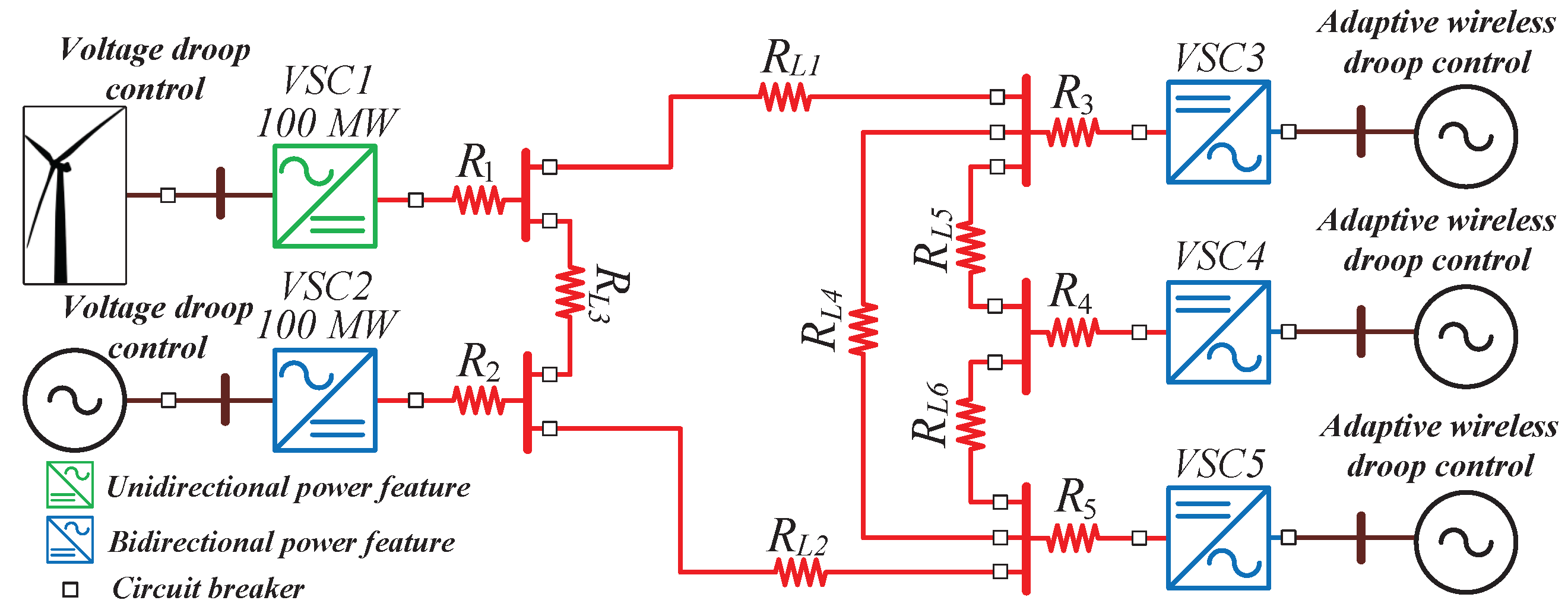
Most of the previous studies on power sharing in the MT-HVDC grid are based on radial systems. However, evaluating the MT-HVDC grid based on a mesh system with multiple converters can more closely emulate a real MT-HVDC operation.
Previous works on power management did not consider the peak demand of different connected inverters.
This article is organized as follows:
Section 2 discusses the MT-HVDC architecture.
Section 3 presents the proposed AWD control methodology.
Section 4 highlights the six cases that are simulated along with a discussion on the results, followed by the conclusion of the paper in
Section 5.
4. Simulation Results and Discussion
The objective of the simulations is to validate the proposed AWD methodology for both the inverters and rectifiers. The simulation results are obtained using PSCAD/EMTDC. Some simulations are run for 20 s and 54 s. The time step for these simulations is set as
s. In the simulations, the proposed method is evaluated under six different cases.
Table 2 shows the specifications and parameters of the MT-HVDC system.
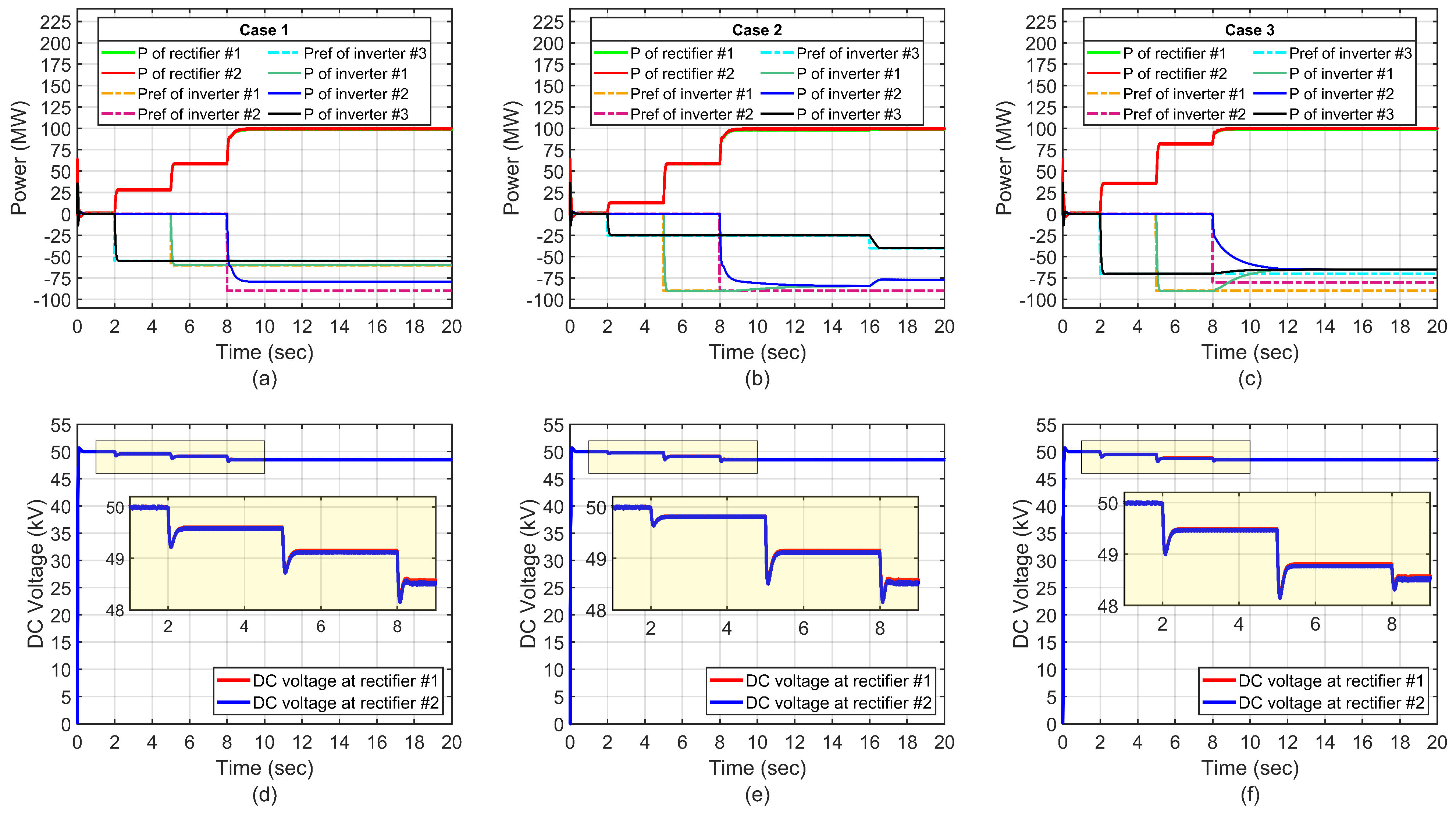
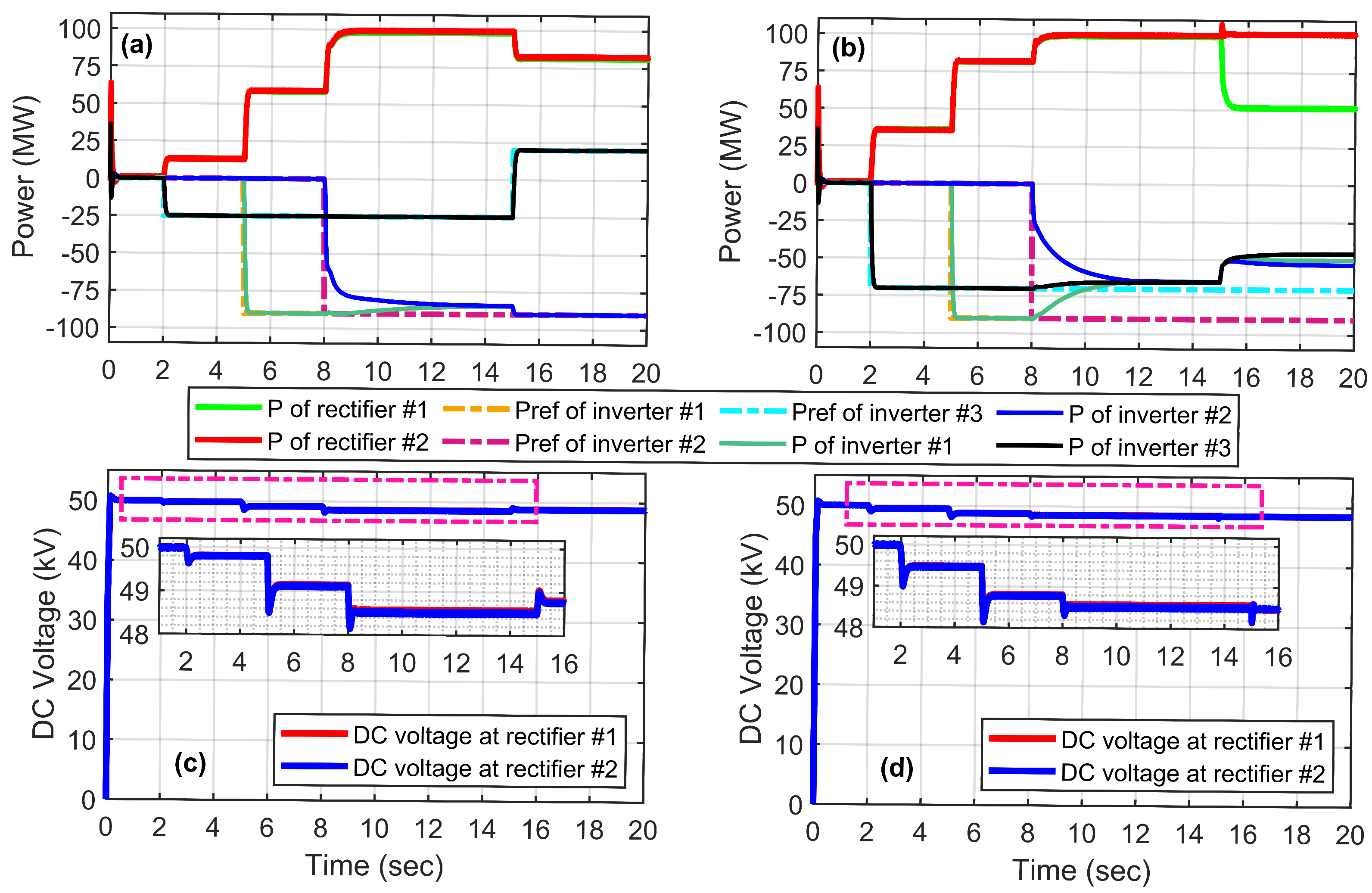
4.1. Case 1: Power Available
Figure 4a shows the simulation result of the proposed AWD in the scenario where inverter 3 requests power above the agreement while inverters
and
request power within the limits of their agreements.
Figure 4b shows the DC-link voltage for this scenario.
Initially, at s, the power flow in the system is equivalent to the system losses since none of the inverters request any power. During this period, the MT-HVDC system’s DC voltage is 50 kV. At s, inverter begins to request 60 MW of power, which is available at the rectifier station, while the remaining inverters are still inactive. Consequently, both rectifiers initiate the delivery of available power to the inverter while maintaining equal power sharing between themselves. Consequently, the DC-link voltage decreases to approximately 49.5 kV.
At s, inverter requests 55 MW of power, which is available at the rectifier station. This request is fulfilled if there are no other requests from the remaining inverters. At the same time, the DC-link voltage decreases to approximately 49.1 kV in accordance with the characteristics of the droop controller.
At
s, inverter
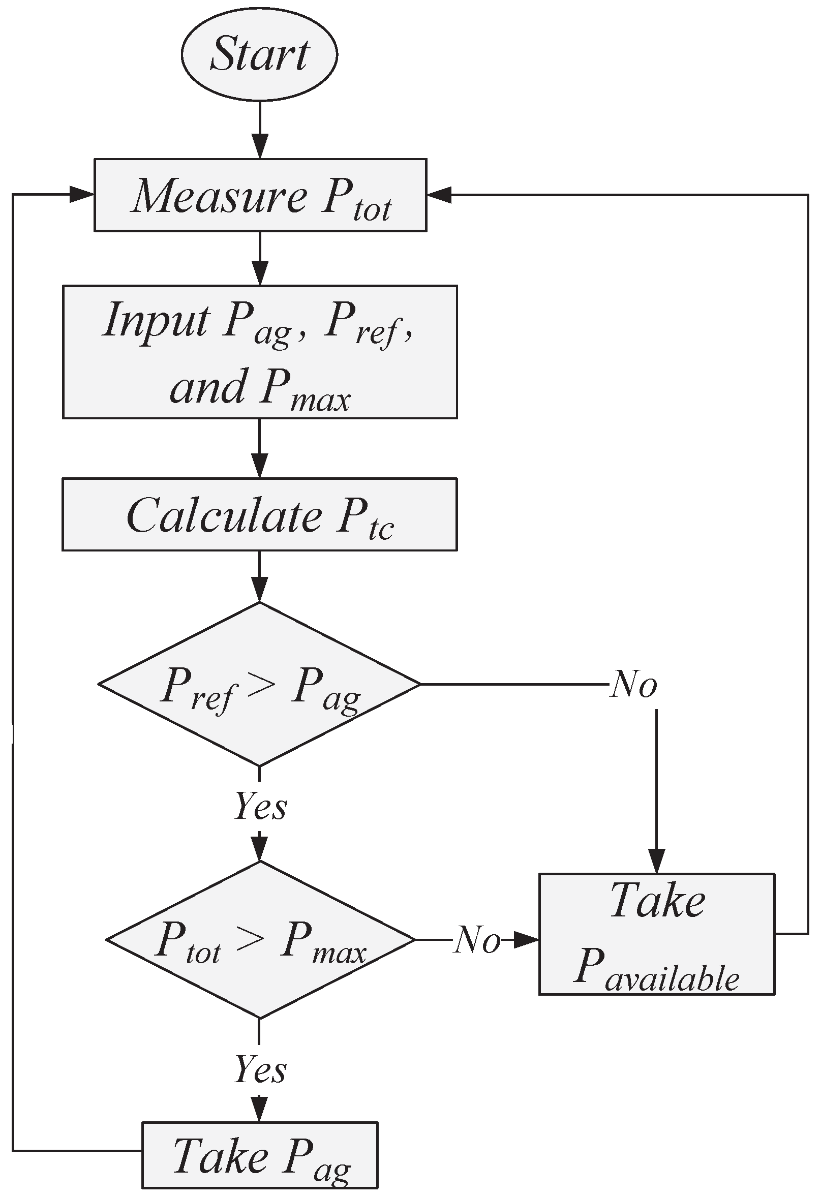
requests 90 MW of power, which is not available at the rectifier station. Consequently, the system will initiate a recalculation based on the flowchart in
Figure 5. This determines the revised available power that can be allocated, which is 80 MW to inverter
. At the same time, the DC voltage further decreases to 48.5 kV. This recalculation enables the system to adjust and allocate the maximum power possible to meet the inverter’s request.
4.2. Case 2: Equal Power Sharing Between Two Inverters
Figure 4c shows the simulation results for the cases of inverters
and
requesting power above their agreement, which is not available at the rectifier station, while inverter
requests power within the limits of the agreement.
Figure 4d shows the DC-link voltage for this scenario.
At s, inverter begins to request 25 MW of power, which is available at the rectifier station, while the remaining inverters are still inactive. Furthermore, both rectifiers deliver the available power to the inverters while maintaining equal power sharing between themselves. Meanwhile, the DC-link voltage decreases to approximately 49.5 kV.
At s, inverter requests 90 MW of power, which is available at the rectifier station. Therefore, the rectifier station grants this request in the absence of any other requests from the remaining inverters. At the same time, the DC-link voltage decreases to approximately 49.1 kV accordingly.
At
s, inverter
requests 90 MW of power, which is not available at the rectifier station. Since the two inverters request more power than their power agreement, the system initiates a recalculation based on the flowchart in
Figure 5 and shares available power equally between inverters
and
. This is observed in
Figure 4c. At the same time, the DC-link voltage also decreases to 48.5 kV.
At s, inverter increases its request to 40 MW. In this scenario, the system recalculates the available power to distribute it equally between inverters and .
4.3. Case 3: Equal Power Sharing Between All Inverters
Figure 4e shows the simulation results for the scenario where all inverters request power above their agreements, which is not available at the rectifier station.
Figure 4f shows the DC-link voltage for this scenario.
At s, inverter requests 90 MW of power, which is available at the rectifier stations, and this request is granted.
At s, inverter requests 90 MW. In this scenario, the power request exceeds the power agreement, and the system shares the available power equally between the inverters, with the DC-link voltage decreasing to approximately 48.8 kV.
At
s, all the inverters requested power above their power agreement. To avoid overloading the system, a recalculation is initiated based on
Figure 5 to share the available power equally among all inverters. At the same time, the DC-link voltage decreases to approximately 48.5 kV.
4.4. Case 4: Rush Power Management State
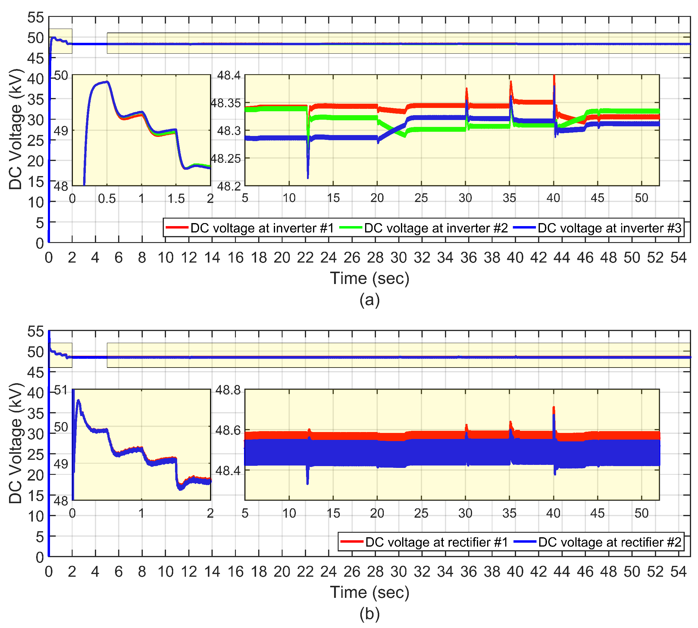
Figure 6 shows the simulation results for the system during rush hour intervals. The rush hour intervals for inverters #1–3 are from 0–20 s, 20–40 s, and 40–55 s, respectively. The power reference for the inverters across the rush hour intervals is shown in
Figure 6.
Figure 7 shows the DC-link voltage variations for these scenarios.
It is observed from
Figure 6 that the inverter having priority will result in a lower voltage drop, resulting in greater available power based on (3). The AVRUA algorithm’s function, illustrated in
Figure 5, in conjunction with the droop concept, aims to establish a non-communications line by determining the voltage drop of each inverter. The measured voltage and current, along with the varying virtual resistance, offer a great deal of precise power sharing.
At
, the priority inverter
increases its power until it reaches the requested power of 85 MW. On the other hand, inverter
has to shed power to the priority inverter and take the available power. This is shown more vividly in the zoomed-in subplot of
Figure 6 for this time interval.
At
s, inverter
increases its power request from 40 MW to 90 MW. Consequently, the priority inverter has to decrease its power to the power agreement level. As long as all requests from other inverters are less than the agreed power at each terminal, the priority inverter can take the remaining power without requiring any communication links. In this particular scenario, both inverters #2 and
adjust their output power to the agreed power level. This is shown in the zoomed-in subplot of
Figure 6 for this time interval.
At
s, inverter
has priority, resulting in a lower voltage droop for it. Furthermore, given inverter
’s priority, the voltage drops for the other two inverters due to a reevaluation of Thevenin resistance,
. This is shown in the zoomed-in subplot of
Figure 6 for this time interval.
At
s, the rush hour inverter changes from inverter
to inverter
, marking a shift in priority. During this interval, the requested power for inverters #1–3 is 80 MW, 90 MW, and 70 MW, respectively. As a result of all requested power being higher than the agreement power levels, the system initiates the process of switching the priority from one inverter to another and adjusts the power for all inverters to the power agreement accordingly. The zoomed-in subplot of
Figure 5 illustrates this process for this time interval.
At s, the priority switches from inverter to inverter , resulting in a seamless transition based on the voltage drop.
At s, while remaining in the rush hour interval, inverter starts to reduce its power request to 60 MW. Inverter receives the requested power, and the remaining available power will be shared equally, as mentioned in the previous cases.
At
s, inverter
reduces its requested power to 50 MW, which is below the agreed power level. In this scenario, the priority inverter will take over the remaining power until inverter
reaches the requested power. Furthermore, inverter
calculates the available power and determines its output power based on
Figure 5. This is shown in the zoomed-in subplot of
Figure 6 for this time interval.
At
s, the priority inverter switches from inverter
to inverter
. During this interval, the requested power of inverters #1–3 is 70 MW, 70 MW, and 90 MW, respectively. In this case, there is an agreement between inverter #1 and #2 to divide the remaining power after the priority inverter has taken its requested power. Hence, inverter
receives
of the power, while inverter
receives
. Additionally, since the requested power exceeds the agreement power for all inverters, the inverters adjust their power to the agreement power level, as shown in
Figure 6.
At s, the priority switches to inverter #3. In this case, the inverters and dynamically change and set the voltage value according to the agreed power.
4.5. Case 5: Proposed Controller in Rectification Mode
Figure 8a,b show the simulation results for the proposed AWD controller in rectification mode. Before 8 s, the simulation results portray a similar scenario to that in case 2. During this time, the inverters receive the requested power from the rectifier stations in the system. At 15 s, it is observed that inverter
becomes a rectifier, as seen by the positive flow of power in the system. As a result, the remaining rectifiers in the system must reduce their power accordingly to match the demands of the remaining inverters, i.e., inverters
and
. This mode inversion by inverter
results in a jump in the DC-link voltage, as is observed at 15 s in
Figure 8b. This case illustrates the effectiveness of the proposed control strategy in handling multiple rectifiers and inverters in the system with mode inversion during operation without resulting in instabilities.
4.6. Case 6: Generation from One Rectifier Reduces by 50%
Figure 8b,d show the simulation results for the proposed controller dealing with a
reduction in generation from the rectifier station. Before 8 s, the simulation portrays a similar scenario to that in case 3. At 15 s, rectifier
reduces its power by
. This case represents the random nature of power generation from the renewable energy resources in the system, like wind or PV stations. The power sharing between the inverters will then have to be recalculated based on the new Thevenin resistance presented to the rectifiers when looking into the mesh system. Considering Equations (1) and (2), it is clear that a change in the current,
, results in a new value for
and hence a new Thevenin equivalent,
. The proposed AWD controller takes this updated
in
Figure 3 to generate the correct power references for inverters #1–3. The power sharing between the inverters will not be equal in this case as each inverter has different line resistances,
, as illustrated in
Figure 2. The unequal power sharing between inverters is clearly evident in the zoomed version of
Figure 8b.
4.7. Quantitative Error Analysis
Two main evaluation metrics are used to measure the performance of the proposed Adaptive Weighted Droop (AWD) control methodology, i.e., voltage deviation (VD%) and power-sharing error (PSE%). Voltage deviation (VD%) measures the percentage deviation between the measured DC voltage at each inverter and the nominal voltage expected at the rectifier station, as determined by the droop control equation. It is defined as
Power-sharing error (PSE%) shows how far off the actual output power of each inverter is from the reference value that the adaptive virtual resistance under allocation (AVRUA) mechanism set for it.
The results of these calculations are summarized in
Table 3, which reports the maximum voltage deviation and average power-sharing error under six different operational scenarios:
These findings validate the robustness of AWD under varied conditions, including scenarios with unequal inverter requests, power scarcity, and load priority dynamics.
In particular, Case 6 demonstrates the system’s ability to recalibrate under generation loss, while Cases 4 and 5 show the effectiveness of adaptive prioritization and mode switching. The relatively low error values across all cases indicate that the adaptive virtual resistance logic significantly enhances the precision and fairness of power distribution.
To further analyze system behavior, time-domain plots of voltage and power trajectories can be introduced, showcasing the controller’s rapid response and stabilization within milliseconds following sudden load changes or inverter reconfiguration. This dynamic stability is the key advantage over traditional fixed droop or communication-reliant methods.


